RELATED APPLICATIONS
-
This application is related to commonly-assigned U.S. Patent Application
Serial Nos. 09/087,344 and 09/087,264, filed on even date hereto, respectively
invented by Stephen Chessin; and Stephen Chessin, Rod Evans, and Michael
Walker. Each of these related patent applications is hereby expressly referenced,
incorporated herein, and made a part hereof.
BACKGROUND OF THE INVENTION
FIELD OF THE INVENTION
-
The field of this invention relates to global register usage and conflict
detection systems, methods, and computer program products, and more
particularly to the indication of global register usage and the detection of usage
conflicts in global registers.
DESCRIPTION OF RELATED ART
-
In particular computer program systems, registers are used to temporarily
hold copies of the contents of variables required by an executing computer
program. Persistent values for variables are stored in memory. It is known to be
useful, moreover, to designate one or more of the registers in a computer program
system as global in scope (that is, used by the entire computer program and not
just by particular modules or subroutines) and to dedicate for the use of the global
registers certain variables which are also of global scope.
-
Since particular programs are linked from individual object modules that
are each compiled separately, different symbols may refer to the same global
register, causing incorrect referencing and scoping of variables. Particular
programs furthermore incorporate code from one or more libraries, which is also
compiled separately, compounding the misreferencing. A severe technical
problem arises when different portions of a particular program each use a single
given global register to contain different variable values. Such a usage tends to
cause incorrect results because the wrong variable value might be in the global
register at the wrong time.
-
Additionally, another technical problem arises with respect to initializing
global values during software operation. While known mechanisms exist for
initializing variables in memory to given values before program execution begins,
there are no such known mechanisms for initializing a register that is to contain a
global variable set to a given value before execution begins.
SUMMARY OF THE INVENTION
-
The invention is defined in claims 1, 8, 15, 16, 17 and 18, respectively.
Particular embodiments of the invention are set out in the dependent claims.
-
According to the present invention, separately compiled software units
expressly indicate their global register usage so that static and dynamic linkers
are able to detect conflicts of usage incident to compilation. Further according to
the present invention, global registers are initialized to desired values before
program execution begins. According to one embodiment of the present
invention, a symbol table type, STT_SPARC_REGISTER, is established to
expressly indicate particular symbol table entries which associate a global symbol
with a particular global register. The "name" portion of a symbol table entry
points to a string that contains the name of the symbol, or else contains a NULL
value to indicate that the register is used for scratch space. The "value" portion
of the symbol table entry indicates the particular register to which this entry
applies. Another portion of the symbol table entry indicates whether there is an
initializer for the particular register. According to another embodiment of the
present invention, a relocation type, R _SPARC_REGISTER, indicates an initial
value for a global register.
-
According to the present invention, a compiler generates symbol table
entries to indicate how a containing object file uses the application-reserved
global registers. A static linker checks the generated symbol table entries for all
object files being combined into a particular target object file to ensure that the
global registers referenced by the different source elements are used compatibly.
The resulting object file produced includes these symbol table entries to indicate
the resulting object global register usage. According to the present invention, the
static linker warns if any shared object file that was referenced during the linking
used the global registers in a fashion incompatible with the object file being built.
According to the present invention, the static linker generates a warning, if a
shared object file is being built that uses application-reserved global registers. A
similar warning is issued according to the present invention by an archiver, if an
archive library is built using application-reserved global registers. A dynamic
linker according to the present invention checks to ensure that all object files
being bound into a selected process have compatible uses of application-reserved
global registers.
-
According to the present invention, a system and method for compiling
and linking a source file includes a compiler for generating a symbol table which
associates particular global symbols with corresponding global registers for
holding variable class information pertaining to global symbols referenced or
defined in the source file. The symbol table information is sufficient to enable a
linker to resolve class definitions and to perform class relocation operations. The
symbol table information is included in to object file generated by the compiler.
The compiler particularly generates object files such that identification of usage
conflicts and performance of relocation operations are delayed until operation of
the linker. A linker links the object file with other object files and shared
libraries to thereby generate either an executable file or a shared library. The list
of other object files and shared libraries may be empty, in which case the linker
generates the executable file or shared library from the single object file. The
linker uses the class information contained in the object file to identify usage
conflicts and to perform relocation operations.
BRIEF DESCRIPTION OF THE DRAWINGS
-
- Figure 1 is a compilation data flow diagram according to a preferred
embodiment of the present invention;
- Figure 2 is a block diagram of a computer system according to a preferred
embodiment of the present invention;
- Figure 3A is a flowchart of a linker process which can be used in
connection with the present invention;
- Figure 3B is a flow chart of a linker process according to one embodiment
of the present invention;
- Figure 4 is a block diagram of an object file produced by a compiler
according to a preferred embodiment of the present invention;
- Figure 5 is a flowchart of a compilation/linking process according to a
preferred embodiment of the present invention;
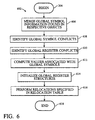
- Figure 6 is a detailed flowchart of link processing according to a preferred
embodiment of the present invention;
- Figure 7 is an example of an information table generated by a compiler
according to a preferred embodiment of the present invention; and
- Figure 8 is an example of a relocation table according to one embodiment
of the present invention.
-
DETAILED DESCRIPTION OF THE PREFERRED EMBODIMENT
-
Figure 1 is a compilation data flow diagram according to a preferred
embodiment of the present invention. In particular, Figure 1 illustrates a
compiler 104, a
static linker 114, and a run-
time linker 118, according to one
implementation of the present invention. The
compiler 104 generates an
object
file 106 from a
source file 102. The
source file 102 is written according to
different embodiments of the present invention in the well-known C, C++, or the
Fortran computer programming languages. It is important to note that the present
invention does not impose restrictions on how developers may use the particular
language selected to produce the
source file 102. According to one embodiment
of the present invention, the
static linker 114 includes a relocation code section
which is used to initialize register symbols. The relocation code section has a
name, .rela; a type SHT_RELA; and no attributes, Accordingly, the following
table is valid:
| Matrix of Legal Combinations of Usage of a Given Register |
| Name | Type | Attributes |
| .rela | SHT_RELA | None |
| .rela sh_link contains the section header index of the associated symbol table;
and sh_info is 0, indicating that this section only contains register
relocations. |
-
The object file 106, as well as zero or more other object files 108, and/or
zero or more shared libraries 110 are transferred to a static linker 114, according
to the present invention. The other object files 108 were previously compiled by
the compiler 104 of the present invention and the shared libraries 110 were
previously created by the static linker 114. The static linker 114 generates an
executable file 116. According to one embodiment of the present invention, the
static linker 114 generates another shared library. As will be appreciated, a
shared library is a form of an object file. Accordingly, the terms "object file" and
"shared library" will be used interchangeably herein. As will be appreciated by
persons skilled in the art, the executable file 116 includes code, data, and other
information from the object files 106, 108, and also contains references to shared
libraries 110 (i.e., code, data, etc. from the shared libraries 110 are not actually
embedded in the executable file 116. During run-time, the executable file 116
and the shred libraries 110 are transferred to a run-time linker 118. The run-time
linker 118 resolves references contained in the executable file 116 to the
shared libraries 110, and produces an execution image 120. The execution image
120 is stored in main memory 208 and is executed by a central processing unit
204 (Fig. 2). Generally speaking, the operation of the static linker 114 and run-time
linker 118 may be broken down into four phases as shown in detail in
Figures 3A and 3B.
-
Figure 2 is a block diagram of a computer system 202 according to a
preferred embodiment of the present invention. The computer system 202
includes one or more processors, such as central processing unit (CPU) 204,
connected to a communication medium, such as a bus 206. A main memory
(e.g., without limitation) random access memory (RAM)) 208 is also connected
to the bus 206. The compiler 104 and linker 112 are stored in the main memory
208. Linker 112 includes according to the present invention a static linker 114, a
run-time or dynamic linker, or both. The source file 102; object files 106 and
108; shared libraries 110; and the execution image 120 are also preferably stored
in the main memory 208. Computer system 202 further includes registers 210. A
computer program product (such as floppy disk 214), comprising a computer
readable media having computer program logic recorded thereon, wherein the
computer logic when executed in the computer system 202 enables the computer
system 202 to perform the functions of the present invention, may be read by an
additional storage device, such as floppy disk drive 212. The computer program
logic, which represents the compiler 104 and the linker 112, may then be loaded
into the main memory 208 (as shown), and executed by the CPU 204. A suitable
form for the computer system 202 is a Sun Microsystems workstation made by
Sun Microsystems, Inc., of Mountain View, California. Any other suitable
computer system could alternatively be used.
-
Figure 3A is a flowchart of a linker process which can be used in
connection with the present invention. Flowchart 302 particularly shows
performance 306 of a read phase in which the static linker 114 and run-time
linker 118 operate to perform read operations after a begin phase 304, a layout
phase 308, a relocation phase 310, and a write phase 312. These linker phases
306, 308, 310, and 312 are well-known to persons skilled in the art. Flowchart
302 is completed with performance of an end phase 314.
-
Figure 3B is a flowchart 352 of a linker process according to one
embodiment of the present invention. In particular, after completion of a begin
phase 354, a read phase is performed 356 in which the static linker 114 and the
run-time linker 118 operate to perform read operations. Thereafter, a layout
phase 358 is performed, which is followed by a relocation phase 360 and a write
to memory phase 362. Thereafter according to the present invention, the global
registers are initialized and control is turned over 366 to the executable image,
followed by completion in an end phase 394.
-
Figure 4 is a block diagram of an object file produced by a compiler
according to a preferred embodiment of the present invention. As shown in
Figure 4, the object file 106 includes code and data 402 and a symbol information
406. According to one embodiment of the present invention, object file 106
additionally includes one or the other or both of symbol table 404 and symbol
table 408. The symbol information 406 according to one embodiment of the
present invention includes a symbol table 408. Further according to one
embodiment of the present invention, the symbol information 406 includes a
relocation table 412. The compiler 104 generates code and data 402 and
information for the symbol table 408 including global symbol and global register
information and embeds such information 406 in the object file 106. Such global
symbol and global register information includes data about global symbols and
global registers which are defined and/or referenced in the source file 102, and
further includes additional information on how such global symbols and global
registers are used by the source file 102. The global symbol and global register
information 406 generated by the compiler 104 particularly enables the linker 112
whether static, dynamic or run-time, to identify global symbol conflicts and
global register conflicts and to perform relocations according to the present
invention.
-
As discussed above, it is not the
compiler 104 that identifies global
symbol conflicts or perform relocations according to the present invention.
Instead, identification of global symbol conflicts is delayed from compile time to
link time according to the present invention. In particular according to Figure 5,
the
compiler 104 is used to generate information about global symbols and how
they are used, according to step 506 which follows a
begin phase 504. Such
information about global symbol conflicts is called
symbol information 406, and
is embedded in the
object file 106 which is produced by the
compiler 104. More
particularly, Figure 5 is a flowchart of a compilation/linking process according to
a preferred embodiment of the present invention. In particular, Figure 5 depicts a
flowchart 502 according to the present invention which represents the high-level
operation of the
compiler 104 and the applicable one of
linkers 114, 118. The
compiler 104 performs
step 506 when compiling the
source file 104, and the
applicable one of
linkers 114, 118 performs
step 508 when processing the object
files 106 and 108, and the shared
libraries 110.
Flowchart 502 begins with
step
504 and control passes to step 506 after completion of the begin phase. The
compiler generates information regarding global symbol table entries to indicate
how the containing object file uses particular application-reserved global
registers. The programmer accordingly indicates to the compiler by flags, for
example, according to one embodiment of the present invention, or to the
assembler by flags or directives according to another embodiment of the present
invention, what the particular register usage is for a selected global register.
According to step 506, the
compiler 104 generates an
object file 106 from the
source file 102. In
step 508, the applicable one of
linkers 114, 118 generates an
executable file 116, and then an
execution image 120 is produced from the object
files 106 and 108, and the shared
libraries 110. As discussed above, during the
generation of the
executable file 116 and the
execution image 120, the
static
linker 114 and the run-
time linker 118 perform a
read phase 306, a
layout phase
308, a
relocation phase 310, and a
write phase 312. According to the present
invention, these linker phases 306, 308, 310, and 312 are modified such that the
static linker 114 and the run-
time linker 118 identify global symbol conflicts and
perform relocations. The operation of the
static linker 114 and the run-
time
linker 118 is further discussed below. After
step 508 is fully performed, the
operation of
flowchart 502 is complete, as indicated by
step 510. The static
linker checks the symbol table entries in the object files being combined into an
executable file or a shared library to ensure that the global registers are used
compatibly. The resulting object includes, according to the present invention,
entries in its symbol table to indicate the resulting object's global register usage.
The static linker warns if any shared library that was referenced during the
linking uses global registers incompatibly with the object being built. Further
according to one embodiment of the present invention, the static linker generates
a warning if a shared object is being built that uses application-reserved global
registers. A similar warning is issued by an archiver, if an archive library is built
containing objects that use application-reserved global registers. The dynamic
linker (ld.so) according to the present invention checks that all object files being
bound into a target process have compatible uses of the application-reserved
global registers. A dlopen() of an object that is not compatible with the particular
selected application process, for example, fails with an error according to the
present invention.
| Matrix of Usage Combinations for a Given Register |
| Obj1\Obj2 | Unused | Scratch | Symbol |
| Unused | OK | OK | OK |
| Scratch | OK | OK | NO |
| Symbol | OK | NO | |
-
The scratch symbol according to the present invention is treated as a
symbol since a null name only matches a null name and scratch registers
according to the present invention have global scope. A matrix of permissible
combinations of st_shndx for the same register symbol follows:
| Matrix of Permissible Combinations of Initialization of a Given Register |
| Obj1\Obj2 | UNDEF | ABS |
| UNDEF | OK | OK |
| ABS | OK | NO |
-
The symbol information 406 according to one embodiment of the present
invention includes (1) a symbol table 408 containing a list of global symbols; and
(2) a relocation table 412 containing a list of global symbols. Using the symbol
information 406, the linker 114 or 118 as applicable, in step 508 determines the
exact layout of global symbol used by an application and then satisfies the
relocations required. The symbol table 408 comprises a plurality of entries,
where each entry corresponds to a symbol. These entries are used by the linkers
114 and 118 during the relocation process.
-
Figure 6 is a detailed flowchart of linker operation according to one
embodiment of the present invention. A linker generally operates according to
four phases: a read phase 306, a layout phase 308, a relocation phase 310, and a
write phase 312 (Figure 3). In the present invention, these linker phases 306,
308, 310, and 312 have been modified such that the applicable linker identifies
global symbol conflicts. Such modification is shown in a flowchart 602 in Figure
6. In particular, step 606 is preferably performed in the read phase 306. Step 608
is preferably performed between the read phase 306 and the layout phase 308.
According to step 610, global symbol conflicts are identified Steps 612 and 614
are preferably performed between the layout phase 308 and the relocation phase
310. Step 616 is preferably performed during the relocation phase 310.
Flowchart 602 shall now be described. Flowchart 602 begins with step 604,
where control immediately passes to step 606. In step 606, the applicable linker
reads in the object files 106, 108 and the shared libraries 110 and merges together
the global symbol information 406 contained in these files. In particular, the
applicable linker merges together the global symbol tables 408 contained in these
files to generate a merged symbol table. Similarly, the applicable linker merges
together the relocation tables 412 to generate a merged relocation table. In step
608, the applicable linker identifies global symbol conflicts. In particular, the
applicable linker processes the merged tables and determines the layout of each
symbol (for example, the size and alignment of each symbol, the number of
fields, the data types of the fields, the number of bytes from the top of the symbol
to each of the fields, etc.) The applicable linker creates a separate data structure
for each symbol, and stores this symbol specific information in such data
structures. These data structures are called "layout data structures" for reference
purposes. Upon the completion of step 608, the applicable linker is aware of all
symbol-related information that are conventionally known by conventional
compilers. In step 612, the applicable linker evaluates the symbols in the merged
symbol table. In particular, the applicable linker determines the value of the
symbol in each entry of the merged symbol table, and stores this value in the
value field of this entry. Consider, for example, the example symbol table 408 in
Figure 7. The applicable linker determines the values of entries 714 and 718 by
referencing the appropriate layout data structure for a particular class. The
applicable linker stores these values in the value fields of these entries 714, 718.
The manner in which the linker 112 calculates the values of other symbol types is
described above. In step 614, to applicable linker initializes global register
structures. In particular, during step 614 the applicable linker generates tables
and table pointer information tables, and stores these tables in the appropriate
data structures that have been allocated. In step 616, the applicable linker
performs the relocations specified in the entries of the merged relocation table.
The manner in which the applicable linker performs this function is described
above. After step 616 is fully performed, the operation of flowchart 602 is
complete, as indicated by step 618. As will be appreciated by persons skilled in
the relevant art, the operation of the applicable linker described above is, in
practice, collectively performed by the static linker 114 and the run-time linker
118. Whether the operations described above are performed by the static linker
114 or the run-time linker 118 is not important in the present invention.
Preferably, however, the static linker 114 attempts to prelink executables and
shared objects so that if the executable and shared objects are in the same state as
when they were created, then the run-time linker 118 needs to only load the files
and start running. In practice, the run-time linker 118 may have to redo many of
the relocations that were done by the static linker 114.
-
Figure 7 is an example of a symbol table generated by a compiler
according to a preferred embodiment of the present invention. Figure 7
particularly shows first and second symbol table entries, 714 and 718, in an
example symbol table 408. Each entry in the symbol table 408 includes
information that identifies the symbol type, and information that indicates the
value of the symbol for this class. Entries for particular symbols may
additionally include further fields including for example symbol name, symbol
size, symbol binding, and a symbol section index. The symbol name when
appropriate contains the name of a member. The list of symbol types is
implementation specific, and depends on a number of factors, such as the
computer programming language and the target machine. Example symbol types
will be apparent to persons skilled in the relevant art.
-
As described below, the applicable linker calculates the values of the
symbols in the symbol table 408 according to the present invention before
processing the relocation entries in the relocation table 412. In processing each
relocation entry, the value is extracted from the symbol table and is stored at the
given address according to the type of the relocation entry. Consider the example
of Figure 7. Prior to processing the relocation entries in the relocation table 412,
the applicable linker evaluates the
symbol entries 714, 718 in the symbol table
408 and reads the value associated with each symbol entry. The applicable linker
then inserts the value read into the value field of the
symbol entry 714.
According to one embodiment of the present invention, the applicable linker
inserts this value (8 bytes) into the value field of the
symbol entry 718. While
processing a particular relocation entry, the applicable linker according to the
present invention replaces a placeholder in the instruction at a particular address
with the value in
symbol entry 714. This may be a case pointer in a relocation
entry which points to
symbol entry 714. Similarly, while processing a particular
relocation entry for relocation table 412, the applicable linker replaces the
placeholder, such as a zero (i.e., "o" for example) in the instruction at a particular
address with the value provided in
symbol entry 714. A register symbol in a
symbol table according to one embodiment of the present invention is indicated
by a specific additional Symbol Type and Value as set forth below:
| Additional Symbol Table Type |
| Name | Value |
| STT_ REGISTER | 13 |
-
A symbol table entry for a register symbol according to one embodiment
of the present invention particularly includes the following elements:
- st_name
- Index into the string table of the name of the
symbol. An index value of 0, which points to the
null name in the string table, indicates that the
register is used for scratch. A scratch register must
have binding STB_GLOBAL.
- st_value
- Register number. Register numbers correspond to
the assignments in the SPARC Architecture
Manual for integer registers.
- st_size
- unused (0)
- st_info
- ELF64_ST_INFO (bind.type)
bind is typically STB_GLOBAL, but does reflect
the actual declared scope of the name (that is, it
could be STB_WEAK or STB_LOCAL).
type must be STT_REGISTER (13) - st_other
- unused (0)
- st_shndx
- SHN_ABS if this object initializes this register
symbol; SHN_UNDEF otherwise. An initializer
for a SHN_ABS register symbol is specified with a
special register relocation type.
-
Absence of an entry for a particular global register indicates that that
particular global register is not used by the object. An object according to the
present invention uses one or more of the application-reserved global registers
and indicates this usage with an appropriate symbol-table entry. The following
dynamic array tag is moreover added to the symbol table according to one
embodiment of the present invention:
| Symbol Table Dynamic Array Tags |
| Name | Value | d_un | Executable | Shared Object |
| DT_REGISTER | 0x7000001 | d_val | optional | optional |
| DT_REGISTER | This element contains the index of an STT_REGISTER symbol. There is one of these entries for every STT_REGISTER symbol table entry in the symbol table. |
-
The compiler 104 according to the present invention accordingly
generates code that is relocated at link-time. In particular, if a variable is
referenced in a source file, the compiler 104 generates both a symbol table 408
and a relocation table 412. According to one embodiment of the present
invention, the generation of symbol and relocation tables is accomplished with a
specialized global register relocation type which is used to identify global
register conflicts and to initialize the global registers prior to execution of the
execution image which is produced.
-
Figure 8 is an example of a relocation table according to one embodiment
of the present invention. The relocation table 412 contains a list of the
relocations which must be performed by the applicable linker during link-time.
Each entry in the relocation table 412 includes a relocation type, an address of
either an instruction or a data element that needs to be relocated, and, in all but
one case, a pointer to an entry in the symbol table 408. The following relocation
type is added to the relocation table according to the present invention:
| Additional Relocation Type |
| Name | Value | Field | Calculation |
| R_SPARC_REGISTER | 54 | V-xword64 | S + A |
| R_SPARC_REGISTER | This relocation type is used to initialize a register symbol. Its offset member contains the register number to be initialized. There must be a corresponding register symbol for this register of type SHN_ABS. |
-
While various embodiments of the present invention have been described
above, it should be understood that they have been presented by way of example
only, and not limitation. Thus, the breadth and scope of the present invention
should not be limited by any of the above-described exemplary embodiments, but
should be defined only in accordance with the following claims and their
equivalents.