EP0962652B1 - Ignition timing control apparatus of on-vehicle internal combustion engine - Google Patents
Ignition timing control apparatus of on-vehicle internal combustion engine Download PDFInfo
- Publication number
- EP0962652B1 EP0962652B1 EP99109880A EP99109880A EP0962652B1 EP 0962652 B1 EP0962652 B1 EP 0962652B1 EP 99109880 A EP99109880 A EP 99109880A EP 99109880 A EP99109880 A EP 99109880A EP 0962652 B1 EP0962652 B1 EP 0962652B1
- Authority
- EP
- European Patent Office
- Prior art keywords
- ignition timing
- engine
- internal combustion
- ignition
- combustion engine
- Prior art date
- Legal status (The legal status is an assumption and is not a legal conclusion. Google has not performed a legal analysis and makes no representation as to the accuracy of the status listed.)
- Expired - Lifetime
Links
Images


Classifications
-
- F—MECHANICAL ENGINEERING; LIGHTING; HEATING; WEAPONS; BLASTING
- F02—COMBUSTION ENGINES; HOT-GAS OR COMBUSTION-PRODUCT ENGINE PLANTS
- F02P—IGNITION, OTHER THAN COMPRESSION IGNITION, FOR INTERNAL-COMBUSTION ENGINES; TESTING OF IGNITION TIMING IN COMPRESSION-IGNITION ENGINES
- F02P5/00—Advancing or retarding ignition; Control therefor
- F02P5/04—Advancing or retarding ignition; Control therefor automatically, as a function of the working conditions of the engine or vehicle or of the atmospheric conditions
- F02P5/145—Advancing or retarding ignition; Control therefor automatically, as a function of the working conditions of the engine or vehicle or of the atmospheric conditions using electrical means
- F02P5/15—Digital data processing
- F02P5/152—Digital data processing dependent on pinking
- F02P5/1521—Digital data processing dependent on pinking with particular means during a transient phase, e.g. starting, acceleration, deceleration, gear change
-
- F—MECHANICAL ENGINEERING; LIGHTING; HEATING; WEAPONS; BLASTING
- F02—COMBUSTION ENGINES; HOT-GAS OR COMBUSTION-PRODUCT ENGINE PLANTS
- F02D—CONTROLLING COMBUSTION ENGINES
- F02D41/00—Electrical control of supply of combustible mixture or its constituents
- F02D41/02—Circuit arrangements for generating control signals
- F02D41/021—Introducing corrections for particular conditions exterior to the engine
- F02D41/0215—Introducing corrections for particular conditions exterior to the engine in relation with elements of the transmission
- F02D41/0225—Introducing corrections for particular conditions exterior to the engine in relation with elements of the transmission in relation with the gear ratio or shift lever position
-
- F—MECHANICAL ENGINEERING; LIGHTING; HEATING; WEAPONS; BLASTING
- F02—COMBUSTION ENGINES; HOT-GAS OR COMBUSTION-PRODUCT ENGINE PLANTS
- F02D—CONTROLLING COMBUSTION ENGINES
- F02D2200/00—Input parameters for engine control
- F02D2200/50—Input parameters for engine control said parameters being related to the vehicle or its components
- F02D2200/501—Vehicle speed
-
- Y—GENERAL TAGGING OF NEW TECHNOLOGICAL DEVELOPMENTS; GENERAL TAGGING OF CROSS-SECTIONAL TECHNOLOGIES SPANNING OVER SEVERAL SECTIONS OF THE IPC; TECHNICAL SUBJECTS COVERED BY FORMER USPC CROSS-REFERENCE ART COLLECTIONS [XRACs] AND DIGESTS
- Y02—TECHNOLOGIES OR APPLICATIONS FOR MITIGATION OR ADAPTATION AGAINST CLIMATE CHANGE
- Y02T—CLIMATE CHANGE MITIGATION TECHNOLOGIES RELATED TO TRANSPORTATION
- Y02T10/00—Road transport of goods or passengers
- Y02T10/10—Internal combustion engine [ICE] based vehicles
- Y02T10/40—Engine management systems
Definitions
- the present invention relates to an ignition timing control apparatus for controlling the ignition timing of a spark plug of an internal combustion engine mounted on a motor vehicle.
- the ignition timing control apparatus of an internal combustion engine mounted on a motor vehicle functions to set a proper ignition timing at which an electric spark is generated by a spark plug in accordance with the operating condition of the engine. For instance, the ignition timing is advanced when the engine is being accelerated to increase the engine speed.
- an ignition timing control apparatus in the case of sudden acceleration, controls to retard the ignition timing when the amount of variation of the throttle valve opening of the internal combustion engine exceeds a specific value, thereby mitigating occurrence of the knocking likely to be caused by a change in engine output during sudden acceleration.
- the ignition timing if retarded in accordance with the amount of change in the opening of the throttle valve, will be retarded after the occurrence of knocking resulting from actual throttle valve operation. This is also in the device which retards the ignition timing when the knocking is detected by the knocking sensor provided in the engine. The related art device, therefore, could not prevent occurrence of the knocking itself.
- an ignition timing control apparatus in which the ignition characteristics are varied depending on the gear position. For this aim for each gear position a separate curve representing the ignition position in dependence from the engine speed is specified (figure 6). In particular when using gear boxes with many gears, such a ignition timing control is rather complex.
- an object of the present invention to provide a simplified ignition timing control apparatus of an internal combustion engine mounted on a motor vehicle which is capable of preventing the occurrence of the knocking.
- the ignition timing control apparatus of the present invention when it has been detected that the engine speed is within the specific range of engine speed and that the transmission gear ratio is high, the engine is regarded to be operating within a knocking range within which the knocking is likely to occur, so that the ignition timing of the internal combustion engine will be retarded. When the engine is thus running within such a knocking range, the ignition timing is instantly retarded to insure generation of electric sparks from a spark plug at a proper ignition timing.
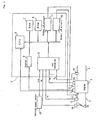
- Fig. 1 shows an on-vehicle engine control system equipped with an ignition timing control apparatus according to the present invention.
- the crank angle sensor 1 comprises a rotor and an electromagnetic pickup (both not shown).
- On the outer periphery of the rotor projections made of a magnetic material are continuously formed at a specific interval of angle (e.g., 30 degrees).
- the electromagnetic pickup is arranged near the outer periphery of the rotor.
- a crank pulse is generated from the electromagnetic pickup at every turn of the rotor through the specific angle in interlock with the rotation of the engine crankshaft (not shown).
- the crank angle sensor 1 generates a TDC signal indicating the piston in each cylinder is at TDC and a reference position signal at every 720-degree turn of the crankshaft.
- the ECU 5 is provided with the CPU 6, RAM 7, ROM 8, counter 9, output interface circuits 10 and 11, and A/D converter 12.
- the counter 9 reset by a crank pulse outputted from the crank angle sensor 1 counts the clock pulse outputted from an unillustrated clock pulse generator, then generating a signal indicating an engine speed Ne.
- the CPU 6 carries out an interrupt process in response to a reference position signal and a TDC signal.
- the CPU 6, RAM 7, ROM 8, counter 9, output interface circuits 10 and 11, and A/D converter 12 are all connected to a common bus.
- the A/D converter 12 is employed to convert, into digital signals, such analog signals from a plurality of sensors which detects engine operation parameters including intake pipe internal pressure P B required in controlling the engine, coolant temperature Tw, throttle valve opening TH, oxygen concentration O 2 in exhaust emissions, and vehicle speed V SP .
- the intake pipe internal pressure P B is detected by the intake pipe internal pressure sensor 13 inserted in the intake pipe 3 located downstream side of a throttle valve 20.
- the coolant temperature Tw is detected by means of a coolant temperature sensor 14.
- the throttle valve opening TH is detected by means of a throttle opening sensor 15.
- the oxygen concentration O 2 in the exhaust emissions is detected by means of an oxygen concentration sensor 16 mounted in the exhaust pipe 4.
- the oxygen concentration sensor 16 is a binary output type oxygen concentration sensor which generates different levels of air-fuel ratio on the rich and lean sides in relation to a stoichometric air fuel ratio as a threshold value.
- the vehicle speed V sp is detected by a vehicle speed sensor 19.
- the CPU 6 executes the fuel injection control routine previously written in the ROM 8, thereby determining the fuel injection time Tout by using these engine operation parameters and the engine speed Ne.
- the CPU 6 executes the ignition timing control routine to thereby set the ignition timing, and generates an ignition instruction through the ignition start control routine in accordance with the ignition timing.
- the ignition timing control routine and the ignition start control routine have been previously written in the ROM 8.
- the output interface circuit 10 drives an injector 17 in accordance with an injector drive instruction from the CPU 6.
- the injector 17 is located in the vicinity of an intake port of the intake pipe 3 of the internal combustion engine, to thereby inject the fuel when driven.
- the output interface circuit 11 stops supplying the current to an unillustrated ignition coil of the ignition system 21 in accordance with an ignition instruction fed from the CPU 6, thereby generating an electric spark at an unillustrated spark plug.
- the current supply to the ignition coil is started at a predetermined crank angle.
- the CPU 6 carries out the ignition timing control routine every specific time (e.g., 10 msec) as follows.
- the CPU 6 first reads the engine speed Ne from output of the counter 9 as shown in Fig. 2 (Step S1), then determines whether or not the engine speed Ne is within the range from the first specific speed N1 (e.g., 1500 rpm) to the second specific speed N2 (e.g., 2500 rpm)
- Step S2 When Ne ⁇ N1 , or Ne ⁇ N2 , the amount of retardation of ignition timing #IGNk for ordinary ignition timing control will be set to zero (Step S3).
- Step S4 the vehicle speed V SP is read from the output of the A/D converter 12 (Step S4), and the transmission gear ratio GR is calculated from the engine speed Ne and the vehicle speed V SP (Step S5). That is, the gear ratio GR is given by calculating Ne/ V SP .
- Step S6 it is determined whether or not the gear ratio GR is high (Step S6) The determination of whether the gear ratio GR is high is done by detecting the gear ratio GR is at or lower the specific value (e.g., 83). In the case the gear ratio is not high, proceed to Step S3 to set the amount of retardation of ignition timing #IGNk to zero.
- the amount of retardation #IGNk is set to perform a retard ignition timing control (Step S7).
- the amount of retardation #IGNk can be retrieved from the amount of retardation data map in the ROM 8 in accordance with the engine speed Ne. For example, as the amount of retardation #IGNk corresponding to the engine speed Ne (NE01 to NE26)has been entered as a retardation amount data map in the ROM 8 as shown in the characteristic curve of Fig. 3, the amount of retardation #IGNk corresponding to the engine speed Ne at that time is read from the retardation amount data map.
- Step S8 the CPU 6 sets the ignition timing IGNk (Step S8).
- the CPU 6 executes an ignition start control routine at a specific crank angle on the basis of an output signal from the crank angle sensor.
- the ignition timer stated above is formed on a program and may be formed of a hardware.
- the ignition timing control apparatus of the present invention when it has been detected that the engine speed is within the specific speed range and the transmission gear ratio is high, the engine is regarded to be operating within an operating range in which the knocking is likely to occur; therefore the ignition timing of the internal combustion engine is retarded. In the knocking range, the ignition timing is instantly retarded to generate a spark arc at the spark plug at a proper ignition timing, thereby preventing occurrence of the knocking.
- the control device determines that the engine (2) is running within an easy-to-knock range in which the knocking is likely to occur. Accordingly an ignition timing retard control of the internal combustion engine (2) is accomplished.
Landscapes
- Engineering & Computer Science (AREA)
- Chemical & Material Sciences (AREA)
- Combustion & Propulsion (AREA)
- Mechanical Engineering (AREA)
- General Engineering & Computer Science (AREA)
- Signal Processing (AREA)
- Electrical Control Of Ignition Timing (AREA)
Description
- The present invention relates to an ignition timing control apparatus for controlling the ignition timing of a spark plug of an internal combustion engine mounted on a motor vehicle.
- The ignition timing control apparatus of an internal combustion engine mounted on a motor vehicle functions to set a proper ignition timing at which an electric spark is generated by a spark plug in accordance with the operating condition of the engine. For instance, the ignition timing is advanced when the engine is being accelerated to increase the engine speed.
- However even when the engine is accelerating, especially during transient operation, e.g., sudden acceleration, in which engine parameters of engine speeds will vary in a short time, no substantial response to the ignition timing control is obtained, sometimes resulting in knocking.
- In Japanese Unexamined Patent Publication No. Hei 1-232169, an ignition timing control apparatus, in the case of sudden acceleration, controls to retard the ignition timing when the amount of variation of the throttle valve opening of the internal combustion engine exceeds a specific value, thereby mitigating occurrence of the knocking likely to be caused by a change in engine output during sudden acceleration.
- In the prior art ignition timing control apparatus, however, the ignition timing, if retarded in accordance with the amount of change in the opening of the throttle valve, will be retarded after the occurrence of knocking resulting from actual throttle valve operation. This is also in the device which retards the ignition timing when the knocking is detected by the knocking sensor provided in the engine. The related art device, therefore, could not prevent occurrence of the knocking itself.
- Furthermore, it is known (patent abstracts of Japan vol. 011, no. 168 (M-594), 29 May 1987 & JP 62 003173 A(TOYOTA MOTOR CORP), 9 January 1987) to control the ignition timing of a car, such that the ignition timing is retarded if a detected degree of acceleration of the car is within a prescribed range and further if a detected gear ratio is within a prescribed range. Also this prior art device does not prevent occurrence of knocking since the high acceleration status of the car results from a respective actual throttle valve operation with a danger of knocking at least for a short time until the ignition timing control apparatus preforms the correction of the ignition timing.
- Furthermore, an ignition timing control apparatus is known (US-A-5 000 148) in which the ignition characteristics are varied depending on the gear position. For this aim for each gear position a separate curve representing the ignition position in dependence from the engine speed is specified (figure 6). In particular when using gear boxes with many gears, such a ignition timing control is rather complex.
- It is therefore, an object of the present invention to provide a simplified ignition timing control apparatus of an internal combustion engine mounted on a motor vehicle which is capable of preventing the occurrence of the knocking.
- This object is solved by the ignition timing control apparatus according to
claim 1. - In the ignition timing control apparatus of the present invention, when it has been detected that the engine speed is within the specific range of engine speed and that the transmission gear ratio is high, the engine is regarded to be operating within a knocking range within which the knocking is likely to occur, so that the ignition timing of the internal combustion engine will be retarded. When the engine is thus running within such a knocking range, the ignition timing is instantly retarded to insure generation of electric sparks from a spark plug at a proper ignition timing.
- A preferred embodiment of the ignition timing control apparatus of the present invention will be described in detail with reference to the accompanying drawings.
- Fig. 1 is a block diagram showing an embodiment of an injection timing control device according to the present invention;
- Fig. 2 is a flowchart showing an ignition timing control routine;
- Fig. 3 is a curve showing a relationship between the engine speed Ne and the amount of ignition retardation #IGNk; and
- Fig. 4 is a flowchart showing the ignition start control routine.
- Fig. 1 shows an on-vehicle engine control system equipped with an ignition timing control apparatus according to the present invention. In the engine control system the
crank angle sensor 1 comprises a rotor and an electromagnetic pickup (both not shown). On the outer periphery of the rotor, projections made of a magnetic material are continuously formed at a specific interval of angle (e.g., 30 degrees). The electromagnetic pickup is arranged near the outer periphery of the rotor. A crank pulse is generated from the electromagnetic pickup at every turn of the rotor through the specific angle in interlock with the rotation of the engine crankshaft (not shown). Thecrank angle sensor 1 generates a TDC signal indicating the piston in each cylinder is at TDC and a reference position signal at every 720-degree turn of the crankshaft. - At the output terminal of the crank angle sensor the ECU (Electronic Control Unit) 5 is connected. The
ECU 5 is provided with theCPU 6, RAM 7,ROM 8,counter 9,output interface circuits 10 and 11, and A/D converter 12. Thecounter 9 reset by a crank pulse outputted from thecrank angle sensor 1 counts the clock pulse outputted from an unillustrated clock pulse generator, then generating a signal indicating an engine speed Ne. TheCPU 6 carries out an interrupt process in response to a reference position signal and a TDC signal. TheCPU 6, RAM 7,ROM 8,counter 9,output interface circuits 10 and 11, and A/D converter 12 are all connected to a common bus. - The A/
D converter 12 is employed to convert, into digital signals, such analog signals from a plurality of sensors which detects engine operation parameters including intake pipe internal pressure PB required in controlling the engine, coolant temperature Tw, throttle valve opening TH, oxygen concentration O2 in exhaust emissions, and vehicle speed VSP. The intake pipe internal pressure PB is detected by the intake pipeinternal pressure sensor 13 inserted in theintake pipe 3 located downstream side of athrottle valve 20. The coolant temperature Tw is detected by means of acoolant temperature sensor 14. The throttle valve opening TH is detected by means of athrottle opening sensor 15. Furthermore, the oxygen concentration O2 in the exhaust emissions is detected by means of an oxygen concentration sensor 16 mounted in theexhaust pipe 4. The oxygen concentration sensor 16 is a binary output type oxygen concentration sensor which generates different levels of air-fuel ratio on the rich and lean sides in relation to a stoichometric air fuel ratio as a threshold value. The vehicle speed Vsp is detected by a vehicle speed sensor 19. TheCPU 6 executes the fuel injection control routine previously written in theROM 8, thereby determining the fuel injection time Tout by using these engine operation parameters and the engine speed Ne. - The
CPU 6 executes the ignition timing control routine to thereby set the ignition timing, and generates an ignition instruction through the ignition start control routine in accordance with the ignition timing. The ignition timing control routine and the ignition start control routine have been previously written in theROM 8. - The
output interface circuit 10 drives aninjector 17 in accordance with an injector drive instruction from theCPU 6. Theinjector 17 is located in the vicinity of an intake port of theintake pipe 3 of the internal combustion engine, to thereby inject the fuel when driven. - The output interface circuit 11 stops supplying the current to an unillustrated ignition coil of the
ignition system 21 in accordance with an ignition instruction fed from theCPU 6, thereby generating an electric spark at an unillustrated spark plug. In this case, the current supply to the ignition coil is started at a predetermined crank angle. - The
CPU 6 carries out the ignition timing control routine every specific time (e.g., 10 msec) as follows. - In the ignition timing control routine, the
CPU 6 first reads the engine speed Ne from output of thecounter 9 as shown in Fig. 2 (Step S1), then determines whether or not the engine speed Ne is within the range from the first specific speed N1 (e.g., 1500 rpm) to the second specific speed N2 (e.g., 2500 rpm) - (Step S2). When Ne<N1 , or Ne≧N2 , the amount of retardation of ignition timing #IGNk for ordinary ignition timing control will be set to zero (Step S3).
- In the meantime, if N1≤Ne<N2, the vehicle speed VSP is read from the output of the A/D converter 12 (Step S4), and the transmission gear ratio GR is calculated from the engine speed Ne and the vehicle speed VSP (Step S5). That is, the gear ratio GR is given by calculating Ne/ VSP. After the calculation, it is determined whether or not the gear ratio GR is high (Step S6) The determination of whether the gear ratio GR is high is done by detecting the gear ratio GR is at or lower the specific value (e.g., 83). In the case the gear ratio is not high, proceed to Step S3 to set the amount of retardation of ignition timing #IGNk to zero. In the case of a high gear ratio, the engine is regarded to be running within the range of knock occurrence; therefore, the amount of retardation #IGNk is set to perform a retard ignition timing control (Step S7). The amount of retardation #IGNk can be retrieved from the amount of retardation data map in the
ROM 8 in accordance with the engine speed Ne. For example, as the amount of retardation #IGNk corresponding to the engine speed Ne (NE01 to NE26)has been entered as a retardation amount data map in theROM 8 as shown in the characteristic curve of Fig. 3, the amount of retardation #IGNk corresponding to the engine speed Ne at that time is read from the retardation amount data map. - After execution of Step S3 or S7, the
CPU 6 sets the ignition timing IGNk (Step S8). The ignition timing IGNk is given by calculating IGNk=IGNk0+#IGNk IGNk0 is the basic ignition timing retrieved as a data map from theROM 8 in accordance with the engine speed Ne and the intake pipe internal pressure PB; for instance, the ignition timing IGNk0 has been set so as to decrease with an increase in the engine speed Ne and a change in the intake pipe internal pressure PB to the atmospheric pressure side - The
CPU 6 executes an ignition start control routine at a specific crank angle on the basis of an output signal from the crank angle sensor. In the ignition start control routine, as shown in Fig. 4, the ignition timing IGNk is set to the ignition timer to start to start down counting (Step S11). Then it is determined whether or not the ignition timer has counted to zero (Step S12). When the ignition timer count = 0, an ignition instruction is generated to the output interface circuit 11 (Step S13). Thus the electric current to the ignition coil of theignition system 21 will be stopped in accordance with the ignition instruction from theCPU 6, causing the spark plug to generate an electric spark. - Therefore, when it has been detected that the engine speed Ne is within the range of N1≦Ne<N2, and the transmission gear ratio is high, the engine is running within a knocking range. In this case, retard ignition is accomplished to retard spark arcing at the spark plug by the amount of ignition retardation #INGk set at Step S7.
- In the above-described embodiment, a single-cylinder internal combustion engine has been described, but the present invention is not limited thereto and is applicable to a multicylinder internal combustion engine.
- It should be noticed that the ignition timer stated above is formed on a program and may be formed of a hardware.
- Furthermore, when the amount of throttle valve opening, or the amount of change in the opening, is under the specific value, it is possible not to retard the ignition timing.
- According to the ignition timing control apparatus of the present invention, as heretofore described, when it has been detected that the engine speed is within the specific speed range and the transmission gear ratio is high, the engine is regarded to be operating within an operating range in which the knocking is likely to occur; therefore the ignition timing of the internal combustion engine is retarded. In the knocking range, the ignition timing is instantly retarded to generate a spark arc at the spark plug at a proper ignition timing, thereby preventing occurrence of the knocking.
- In summary it is an object of the invention to provide an ignition timing control apparatus of an internal combustion engine (2) mounted on a motor vehicle which can prevent occurrence of the knocking.
- When the engine (2) is running within a specific speed range and the transmission gear ratio (GR) is high, the control device determines that the engine (2) is running within an easy-to-knock range in which the knocking is likely to occur. Accordingly an ignition timing retard control of the internal combustion engine (2) is accomplished.
-
- 1
- crank angle sensor
- 2
- engine
- 3
- intake pipe
- 4
- exhaust pipe
- 5
- ECU
- 15
- throttle opening sensor
- 16
- oxygen concentration sensor
- 17
- injector
- 20
- throttle valve
- 21
- ignition system
Claims (1)
- An ignition timing control apparatus of an on-vehicle internal combustion engine (2), comprising:a basic ignition timing generating means for generating a basic ignition timing (ICNKO) in accordance with an engine speed (Ne) and an intake pipe internal pressure (PB);an engine speed detecting means for detecting to see that an internal combustion engine (2) mounted on a motor vehicle is running within a specific range of engine speed, the specific range extending from a first specific speed (N1) to a second specific speed (N2);a means for detecting the gear ratio (GR) of a transmission mounted on said motor vehicle; andan ignition timing retard control means for only retarding the ignition timing of said internal combustion engine (2) with respect to the basic ignition timing (ICNkO) when it has been detected that said engine speed (Ne) is within the specific range of engine speed and that the gear ratio (GR) of said transmission is higher than a specific value.
Applications Claiming Priority (2)
| Application Number | Priority Date | Filing Date | Title |
|---|---|---|---|
| JP15628398 | 1998-06-04 | ||
| JP10156283A JPH11351112A (en) | 1998-06-04 | 1998-06-04 | Ignition timing controller for on-vehicle internal combustion engine |
Publications (3)
| Publication Number | Publication Date |
|---|---|
| EP0962652A2 EP0962652A2 (en) | 1999-12-08 |
| EP0962652A3 EP0962652A3 (en) | 2002-05-15 |
| EP0962652B1 true EP0962652B1 (en) | 2007-02-21 |
Family
ID=15624441
Family Applications (1)
| Application Number | Title | Priority Date | Filing Date |
|---|---|---|---|
| EP99109880A Expired - Lifetime EP0962652B1 (en) | 1998-06-04 | 1999-05-19 | Ignition timing control apparatus of on-vehicle internal combustion engine |
Country Status (4)
| Country | Link |
|---|---|
| US (1) | US6213913B1 (en) |
| EP (1) | EP0962652B1 (en) |
| JP (1) | JPH11351112A (en) |
| DE (1) | DE69935178T2 (en) |
Families Citing this family (4)
| Publication number | Priority date | Publication date | Assignee | Title |
|---|---|---|---|---|
| JP3628288B2 (en) * | 2001-08-29 | 2005-03-09 | 本田技研工業株式会社 | Ignition timing control device for internal combustion engine |
| US7775934B2 (en) * | 2007-03-05 | 2010-08-17 | Honda Motor Co., Ltd. | Control system and method for internal combustion engine |
| FR2985547B1 (en) * | 2012-01-10 | 2014-01-24 | Peugeot Citroen Automobiles Sa | ADVANCE CONTROL METHOD FOR OPERATING IGNITION OF AN INTERNAL COMBUSTION ENGINE |
| JP6323418B2 (en) * | 2015-09-07 | 2018-05-16 | トヨタ自動車株式会社 | Vehicle control device |
Family Cites Families (10)
| Publication number | Priority date | Publication date | Assignee | Title |
|---|---|---|---|---|
| JPS5948307B2 (en) * | 1979-02-23 | 1984-11-26 | 日産自動車株式会社 | Internal combustion engine ignition timing control device |
| JPS56165771A (en) * | 1980-05-23 | 1981-12-19 | Nissan Motor Co Ltd | Engine |
| JPS5793681A (en) * | 1980-12-04 | 1982-06-10 | Nissan Motor Co Ltd | Knock-avoiding device |
| JPS58131359A (en) * | 1982-01-30 | 1983-08-05 | Nissan Motor Co Ltd | Ignition timing control device for internal-combustion engine |
| JPH0742911B2 (en) * | 1985-06-29 | 1995-05-15 | トヨタ自動車株式会社 | Ignition timing control device for internal combustion engine |
| DE3623829C2 (en) * | 1986-07-15 | 1998-01-15 | Audi Ag | Device for controlling the ignition timing of an internal combustion engine |
| US4745901A (en) * | 1987-02-24 | 1988-05-24 | General Motors Corporation | Control method for protecting an IC engine during extended heavy loading |
| JPH01232169A (en) | 1988-03-12 | 1989-09-18 | Mazda Motor Corp | Ignition timing control device for engine |
| JPH02157456A (en) * | 1988-12-12 | 1990-06-18 | Nissan Motor Co Ltd | Device for controlling output of engine of vehicle |
| US5000148A (en) * | 1990-04-16 | 1991-03-19 | Kokusan Denki Company, Ltd. | System and method for controlling ignition of internal combustion engine for vehicle |
-
1998
- 1998-06-04 JP JP10156283A patent/JPH11351112A/en active Pending
-
1999
- 1999-05-19 EP EP99109880A patent/EP0962652B1/en not_active Expired - Lifetime
- 1999-05-19 DE DE69935178T patent/DE69935178T2/en not_active Expired - Fee Related
- 1999-06-04 US US09/325,750 patent/US6213913B1/en not_active Expired - Fee Related
Also Published As
| Publication number | Publication date |
|---|---|
| DE69935178T2 (en) | 2007-12-20 |
| EP0962652A3 (en) | 2002-05-15 |
| US6213913B1 (en) | 2001-04-10 |
| EP0962652A2 (en) | 1999-12-08 |
| JPH11351112A (en) | 1999-12-21 |
| DE69935178D1 (en) | 2007-04-05 |
Similar Documents
| Publication | Publication Date | Title |
|---|---|---|
| US4373489A (en) | Spark timing control system | |
| US4445477A (en) | Method and apparatus for ignition system spark timing control during no-load engine operation | |
| US4442813A (en) | Method of and apparatus for controlling the ignition timing of an internal combustion engine | |
| US4367711A (en) | Method and apparatus for ignition system spark timing control within warm-up period of the engine | |
| US4949691A (en) | System and method for controlling ignition timing for internal combustion engine | |
| KR900003859B1 (en) | Device for controlling internal combustion engine | |
| US4626997A (en) | Method of and system for controlling ignition timing retard limit in internal combustion engine | |
| EP0962652B1 (en) | Ignition timing control apparatus of on-vehicle internal combustion engine | |
| US5040509A (en) | Control system for controlling spark timing for engine | |
| US4930477A (en) | System and method for controlling ignition timing for internal combustion engine | |
| US4854285A (en) | Electronic control circuit for internal-combustion engines | |
| US6234147B1 (en) | Ignition timing control device for internal combustion engine | |
| JPH0263097B2 (en) | ||
| US4987874A (en) | Control system for controlling spark timing of engine | |
| JP5086922B2 (en) | Ignition timing control device for internal combustion engine | |
| JPH0636301Y2 (en) | Ignition timing control device for internal combustion engine | |
| JP3230383B2 (en) | Misfire detection device for multi-cylinder internal combustion engine | |
| JPH0242177A (en) | Ignition timing control device for internal combustion engine | |
| JPS60164234A (en) | Abnormality judging method for knocking detector | |
| JP2606283B2 (en) | Ignition timing control device for internal combustion engine | |
| JPS61283748A (en) | Acceleration shock relieving device in internal-combustion engine | |
| JPH0828365A (en) | Exhaust gas recirculation control device | |
| JPH07217467A (en) | Driving force control device for vehicle | |
| JP2560313B2 (en) | Internal combustion engine rotation sensor abnormality detection method | |
| JP2747718B2 (en) | Ignition timing control device for internal combustion engine |
Legal Events
| Date | Code | Title | Description |
|---|---|---|---|
| PUAI | Public reference made under article 153(3) epc to a published international application that has entered the european phase |
Free format text: ORIGINAL CODE: 0009012 |
|
| AK | Designated contracting states |
Kind code of ref document: A2 Designated state(s): AT BE CH CY DE DK ES FI FR GB GR IE IT LI LU MC NL PT SE |
|
| AX | Request for extension of the european patent |
Free format text: AL;LT;LV;MK;RO;SI |
|
| PUAL | Search report despatched |
Free format text: ORIGINAL CODE: 0009013 |
|
| AK | Designated contracting states |
Kind code of ref document: A3 Designated state(s): AT BE CH CY DE DK ES FI FR GB GR IE IT LI LU MC NL PT SE |
|
| AX | Request for extension of the european patent |
Free format text: AL;LT;LV;MK;RO;SI |
|
| RIC1 | Information provided on ipc code assigned before grant |
Free format text: 7F 02P 5/152 A, 7F 02D 41/02 B |
|
| 17P | Request for examination filed |
Effective date: 20020704 |
|
| AKX | Designation fees paid |
Designated state(s): DE FR GB IT |
|
| 17Q | First examination report despatched |
Effective date: 20050629 |
|
| GRAP | Despatch of communication of intention to grant a patent |
Free format text: ORIGINAL CODE: EPIDOSNIGR1 |
|
| GRAS | Grant fee paid |
Free format text: ORIGINAL CODE: EPIDOSNIGR3 |
|
| GRAA | (expected) grant |
Free format text: ORIGINAL CODE: 0009210 |
|
| AK | Designated contracting states |
Kind code of ref document: B1 Designated state(s): DE FR GB IT |
|
| REG | Reference to a national code |
Ref country code: GB Ref legal event code: FG4D |
|
| REF | Corresponds to: |
Ref document number: 69935178 Country of ref document: DE Date of ref document: 20070405 Kind code of ref document: P |
|
| ET | Fr: translation filed | ||
| PGFP | Annual fee paid to national office [announced via postgrant information from national office to epo] |
Ref country code: GB Payment date: 20070516 Year of fee payment: 9 |
|
| PLBE | No opposition filed within time limit |
Free format text: ORIGINAL CODE: 0009261 |
|
| STAA | Information on the status of an ep patent application or granted ep patent |
Free format text: STATUS: NO OPPOSITION FILED WITHIN TIME LIMIT |
|
| PGFP | Annual fee paid to national office [announced via postgrant information from national office to epo] |
Ref country code: IT Payment date: 20070507 Year of fee payment: 9 |
|
| 26N | No opposition filed |
Effective date: 20071122 |
|
| PGFP | Annual fee paid to national office [announced via postgrant information from national office to epo] |
Ref country code: FR Payment date: 20070510 Year of fee payment: 9 |
|
| PGFP | Annual fee paid to national office [announced via postgrant information from national office to epo] |
Ref country code: DE Payment date: 20080522 Year of fee payment: 10 |
|
| GBPC | Gb: european patent ceased through non-payment of renewal fee |
Effective date: 20080519 |
|
| REG | Reference to a national code |
Ref country code: FR Ref legal event code: ST Effective date: 20090119 |
|
| PG25 | Lapsed in a contracting state [announced via postgrant information from national office to epo] |
Ref country code: FR Free format text: LAPSE BECAUSE OF NON-PAYMENT OF DUE FEES Effective date: 20080602 |
|
| PG25 | Lapsed in a contracting state [announced via postgrant information from national office to epo] |
Ref country code: GB Free format text: LAPSE BECAUSE OF NON-PAYMENT OF DUE FEES Effective date: 20080519 |
|
| PG25 | Lapsed in a contracting state [announced via postgrant information from national office to epo] |
Ref country code: IT Free format text: LAPSE BECAUSE OF NON-PAYMENT OF DUE FEES Effective date: 20080519 |
|
| PG25 | Lapsed in a contracting state [announced via postgrant information from national office to epo] |
Ref country code: DE Free format text: LAPSE BECAUSE OF NON-PAYMENT OF DUE FEES Effective date: 20091201 |