EP0962623A2 - Well completion tool with fluid passages - Google Patents
Well completion tool with fluid passages Download PDFInfo
- Publication number
- EP0962623A2 EP0962623A2 EP99304333A EP99304333A EP0962623A2 EP 0962623 A2 EP0962623 A2 EP 0962623A2 EP 99304333 A EP99304333 A EP 99304333A EP 99304333 A EP99304333 A EP 99304333A EP 0962623 A2 EP0962623 A2 EP 0962623A2
- Authority
- EP
- European Patent Office
- Prior art keywords
- fluid
- passage
- flowpath
- plug
- tool
- Prior art date
- Legal status (The legal status is an assumption and is not a legal conclusion. Google has not performed a legal analysis and makes no representation as to the accuracy of the status listed.)
- Withdrawn
Links
- 239000012530 fluid Substances 0.000 title claims abstract description 218
- 238000004891 communication Methods 0.000 claims abstract description 19
- 238000001914 filtration Methods 0.000 claims description 46
- 238000000034 method Methods 0.000 claims description 17
- 238000006073 displacement reaction Methods 0.000 claims description 15
- 238000010008 shearing Methods 0.000 claims description 5
- 239000013618 particulate matter Substances 0.000 description 11
- 230000015572 biosynthetic process Effects 0.000 description 8
- 238000012856 packing Methods 0.000 description 4
- 238000007789 sealing Methods 0.000 description 3
- 239000002002 slurry Substances 0.000 description 3
- 230000000638 stimulation Effects 0.000 description 3
- 238000005553 drilling Methods 0.000 description 2
- 239000002184 metal Substances 0.000 description 2
- 238000007792 addition Methods 0.000 description 1
- 239000004568 cement Substances 0.000 description 1
- 238000012217 deletion Methods 0.000 description 1
- 230000037430 deletion Effects 0.000 description 1
- 238000012986 modification Methods 0.000 description 1
- 230000004048 modification Effects 0.000 description 1
- -1 proppant or gravel Substances 0.000 description 1
- 230000001681 protective effect Effects 0.000 description 1
- 230000000246 remedial effect Effects 0.000 description 1
- 230000000717 retained effect Effects 0.000 description 1
- 238000006467 substitution reaction Methods 0.000 description 1
Images


Classifications
-
- E—FIXED CONSTRUCTIONS
- E21—EARTH OR ROCK DRILLING; MINING
- E21B—EARTH OR ROCK DRILLING; OBTAINING OIL, GAS, WATER, SOLUBLE OR MELTABLE MATERIALS OR A SLURRY OF MINERALS FROM WELLS
- E21B34/00—Valve arrangements for boreholes or wells
- E21B34/06—Valve arrangements for boreholes or wells in wells
- E21B34/063—Valve or closure with destructible element, e.g. frangible disc
-
- E—FIXED CONSTRUCTIONS
- E21—EARTH OR ROCK DRILLING; MINING
- E21B—EARTH OR ROCK DRILLING; OBTAINING OIL, GAS, WATER, SOLUBLE OR MELTABLE MATERIALS OR A SLURRY OF MINERALS FROM WELLS
- E21B43/00—Methods or apparatus for obtaining oil, gas, water, soluble or meltable materials or a slurry of minerals from wells
- E21B43/02—Subsoil filtering
- E21B43/04—Gravelling of wells
- E21B43/045—Crossover tools
-
- E—FIXED CONSTRUCTIONS
- E21—EARTH OR ROCK DRILLING; MINING
- E21B—EARTH OR ROCK DRILLING; OBTAINING OIL, GAS, WATER, SOLUBLE OR MELTABLE MATERIALS OR A SLURRY OF MINERALS FROM WELLS
- E21B43/00—Methods or apparatus for obtaining oil, gas, water, soluble or meltable materials or a slurry of minerals from wells
- E21B43/25—Methods for stimulating production
- E21B43/26—Methods for stimulating production by forming crevices or fractures
Definitions
- a well completion tool operatively positionable within a subterranean well, the tool comprising: a fluid delivery flowpath configured for delivering fluid into the well; a fluid return flowpath configured for returning fluid from the well; and a first pressure relief device in fluid communication with the fluid delivery and fluid return flowpaths, the first pressure relief device being operative to provide fluid communication between the fluid delivery and fluid return flowpaths upon application of a first predetermined fluid pressure differential between the fluid delivery flowpath and the fluid return flowpath.
- a filtering device is disposed within the passage.
- the filtering device may be positioned between the one of the passage opposite ends and the plug.
- the filtering device may include a series of slots formed therethrough, the slots permitting fluid flow therethrough, but substantially preventing particulate flow therethrough.
- the pressure relief device further comprises a securement member, the securement member securing the filtering device relative to the passage.
- the securement member may further secure the release member relative to the passage.
- the fluid delivery flowpath extends to an exterior portion of the well tool and the fluid return flowpath extends to an interior portion of the well tool, the interior and exterior portions being separated by a sidewall portion of the well tool, and in the actuating step the pressure relief device provides fluid communication between the interior and exterior portions through the sidewall portion.
- the method further comprises the step of filtering fluid flowing between the fluid delivery and return flowpaths.
- the filtering step may be performed by disposing a filtering device relative to the fluid passage, so that fluid flowing through the fluid passage is filtered by the filtering device.
- the filtering device may be disposed on an opposite side of the sidewall portion relative to the sleeve.
- the plug 66 is releasably secured in the passage 68 by one or more release members 72.
- the release members 72 are shear members or shear pins.
- the shear pins 72 are sized to shear upon application of a predetermined differential pressure to the plug 66, that is, a difference in pressure between the fluid delivery flowpath 56 and the fluid return flowpath 62.
- the shear pins 72 are sized to shear at a differential pressure less than that which would cause damage to the tool 10.
- other types of release members such as shear rings, shear screws, collets, etc., may be used in place of the shear pins 72 without departing from the principles of the present invention.
Landscapes
- Life Sciences & Earth Sciences (AREA)
- Engineering & Computer Science (AREA)
- Geology (AREA)
- Mining & Mineral Resources (AREA)
- Physics & Mathematics (AREA)
- Environmental & Geological Engineering (AREA)
- Fluid Mechanics (AREA)
- General Life Sciences & Earth Sciences (AREA)
- Geochemistry & Mineralogy (AREA)
- Earth Drilling (AREA)
Abstract
Description
- The present invention relates generally to wellsite operations, and, more particularly, relates to a well completion tool, especially a well completion tool having a pressure relief capability incorporated therein.
- In many wellsite operations, fluid is delivered into a well and then returned. For example, in drilling operations, drilling mud is typically circulated into a well through a drill string and returned to the earth's surface through an annulus formed between the drill string and the wellbore. In stimulation operations, fluid may be delivered to the wellbore through a fluid delivery flowpath of a well tool and returned along a fluid return flowpath.
- Where the stimulation operation is, for example, a formation fracturing operation, proppant may be suspended in the fluid when it is delivered to the wellbore by pumps at the earth's surface. To prevent return of the proppant with the fluid through the fluid return flowpath, one or more screens are generally attached to the well tool, so that the returned fluid does not include the proppant. Unfortunately, where very high flow rates are used, the wellbore surrounding the well tool may fill quickly with proppant, covering the screens, substantially restricting fluid flow therethrough and creating excessive differential pressure across portions of the well tool. This situation may occur so rapidly that there is not enough time to shut down the pumps and prevent collapse of the screens and/or other portions of the well tool. The problem also exists in other well completion operations, such as gravel packing.
- In the past, attempts to remedy this problem have focused on preventing excessive pressure differentials from being applied to the well tool at the earth's surface. For example, sensors may be utilized at the earth's surface to monitor the pressure applied to the fluid delivered into the well and the pressure of the fluid returned from the well. If the differences between the pressures become excessive, the pumps may be slowed or stopped as needed to decrease the pressure differential.
- In very high flow rate operations, however, the distance between the well tool and the sensors, and the resulting stored energy in the large mass of fluid flowing through the delivery and return flowpaths, produces a significant lag between the time at which remedial measures are taken at the earth's surface and the time at which a decrease in the pressure differential is experienced at the well tool.
- From the foregoing, it can be seen that it would be quite desirable to provide pressure relief capabilities in well tools utilized in wellsite operations. In particular, these pressure relief capabilities could be incorporated into the well tool, in order to minimize any time lag between the occurrence of excessive differential pressure and relief of that differential pressure. Additionally, where the fluid may carry particulate matter, such as proppant or gravel, a pressure relief device incorporated in the tool could include a filtering device. It is accordingly an object of the present invention to provide such a well tool and associated methods.
- In carrying out the principles of the present invention, in accordance with an embodiment thereof, a well tool is provided which includes a pressure relief device incorporated therein. The pressure relief device is in fluid communication with fluid delivery and fluid return flowpaths of the well tool. When a predetermined differential pressure is experienced between the delivery and return flowpaths, the pressure relief device opens to permit fluid flow between the flowpaths, thereby relieving the pressure differential. The pressure relief device may include a filtering device for filtering particulate matter from the fluid. Associated methods of protecting well tools are also provided.
- One pressure relief device disclosed herein includes a plug sealingly disposed within a fluid passage of the well tool. Each opposite end of the fluid passage is in fluid communication with one of the fluid delivery and return flowpaths. The plug is releasably secured in the fluid passage, so that, when the predetermined differential pressure is applied, the plug displaces relative to the passage and permits flow therethrough. In the exemplary embodiment described below, the pressure relief device is installed in a crossover housing of a well completion tool of the type used in formation fracturing and gravel packing operations.
- Another pressure relief device disclosed herein includes a sleeve slidingly and sealingly engaged with a sidewall portion of the well tool. The sidewall separates the fluid delivery and return flowpaths. When the predetermined differential pressure is applied, the sleeve is released for displacement relative to the sidewall, thereby permitting fluid flow through a fluid passage formed through the sidewall, and relieving the differential pressure. The pressure relief devices described herein may be used separately, in combination with each other, in combination with other methods, and in other types of well tools and wellsite operations.
- According to one aspect of the invention there is provided a well completion tool operatively positionable within a subterranean well, the tool comprising: a fluid delivery flowpath configured for delivering fluid into the well; a fluid return flowpath configured for returning fluid from the well; and a first pressure relief device in fluid communication with the fluid delivery and fluid return flowpaths, the first pressure relief device being operative to provide fluid communication between the fluid delivery and fluid return flowpaths upon application of a first predetermined fluid pressure differential between the fluid delivery flowpath and the fluid return flowpath.
- In an embodiment, the fluid delivery flowpath extends to an exterior portion of the well completion tool, and the fluid return flowpath extends to an interior portion of the well completion tool separated from the exterior portion by a sidewall portion of the well completion tool.
- In one embodiment, the first pressure relief device includes a plug releasably secured in a passage formed through a pressure-bearing wall of a housing of the well completion tool, the wall separating the fluid delivery flowpath from the fluid return flowpath. The plug may be releasably secured in the passage by at least one shear member, the shear member shearing upon application of the first fluid pressure differential. A filtering device may be disposed between the fluid delivery flowpath and the plug. The filtering device may comprise a member having a series of slots formed therethrough. The plug may be generally cylindrical-shaped and may carry a circumferential seal externally thereon, the seal sealingly engaging the passage. The filtering device may be generally disc-shaped and may be disposed between the fluid delivery flowpath and the plug, the filtering device providing fluid communication between the fluid delivery flowpath and the plug, but substantially preventing flow of particulate matter from the fluid delivery flowpath to the fluid return flowpath.
- In this embodiment, the well completion tool may further comprise a second pressure relief device, the second pressure relief device providing fluid communication between interior and exterior portions of the well completion tool through the sidewall portion thereof upon application of a second fluid pressure differential between the interior and exterior portions of the well completion tool. The second pressure relief device may include a sleeve releasably secured relative to the sidewall portion, the sleeve displacing relative to the sidewall portion and permitting fluid communication between the interior and exterior portions upon application of the second fluid pressure differential. The second pressure relief device may further include a filtering device disposed relative to the sidewall portion, the filtering device substantially preventing flow of particulate matter through the sidewall portion when the sleeve displaces relative to the sidewall portion.
- In another embodiment, the first pressure relief device may provide fluid communication through the sidewall portion upon application of the first fluid pressure differential. In this embodiment, the first pressure relief device includes a sleeve releasably secured relative to the sidewall portion, the sleeve displacing relative to the sidewall portion and permitting fluid communication between the interior and exterior portions upon application of the first fluid pressure differential. In this embodiment, the first pressure relief device further includes a filtering device disposed relative to the sidewall portion, the filtering device substantially preventing flow of particulate matter through the sidewall portion when the sleeve displaces relative to the sidewall portion.
- According to another aspect of the invention there is provided a pressure relief device for use in a well tool having first and second internal flowpaths, the device comprising: a fluid passage having opposite ends and a seal surface formed between the opposite ends, one of the opposite ends being fluid communicable with the first flowpath, and the other opposite end being fluid communicable with the second flowpath; a plug disposed at least partially within the passage, the plug sealingly engaging the passage and preventing fluid flow therethrough; and at least one release member releasably securing the plug relative to the passage, the release member releasing the plug for displacement relative to the passage when fluid pressure in the passage at one of the opposite ends exceeds fluid pressure at the other of the opposite ends by a predetermined amount.
- In an embodiment, the plug is sealingly disengaged from the passage when the release member releases the plug, thereby permitting fluid flow through the passage.
- In an embodiment, a filtering device is disposed within the passage. The filtering device may be positioned between the one of the passage opposite ends and the plug. The filtering device may include a series of slots formed therethrough, the slots permitting fluid flow therethrough, but substantially preventing particulate flow therethrough.
- In an embodiment, the pressure relief device further comprises a securement member, the securement member securing the filtering device relative to the passage. The securement member may further secure the release member relative to the passage.
- In an embodiment, the pressure relief device further comprises a containment member secured relative to the passage other opposite end, the containment member limiting displacement of the plug relative to the passage other opposite end when the release member releases the plug for displacement relative to the passage.
- According to another aspect of the invention there is provided a pressure relief device, comprising: a housing having a sidewall portion separating interior and exterior portions of the housing; at least one fluid passage formed through the sidewall portion; a sleeve reciprocably and sealingly disposed relative to the sidewall portion between first and second positions, the sleeve preventing fluid flow through the fluid passage in the first position, and the sleeve permitting fluid flow through the fluid passage in the second position; and a filtering device, the filtering device substantially preventing particulate flow through the fluid passage when the sleeve is in the second position.
- In an embodiment, the sleeve is releasably secured against displacement relative to the sidewall portion.
- In an embodiment, the pressure relief device further comprises at least one shear member releasably securing the sleeve against displacement relative to the sidewall portion. The shear member may shear upon application of a predetermined fluid pressure differential between the interior and exterior portions of the housing.
- In an embodiment, the sleeve sealingly engages the sidewall portion at first and second diameters, the first and second diameters straddling the fluid passage. The first diameter is preferably greater than the second diameter.
- In an embodiment, a differential area is formed between the first and second diameters, and a shear member is provided for preventing displacement of the sleeve relative to the sidewall portion until a predetermined differential fluid pressure is applied to the differential area.
- In an embodiment, the filtering device is attached to the exterior of the sidewall portion and the sleeve is sealingly engaged with the interior of the sidewall portion.
- According to another aspect of the invention there is provided a method of protecting a well completion tool, the method comprising the steps of: sealingly engaging a plug within a fluid passage of the well completion tool, the passage extending between a fluid delivery flowpath and a fluid return flowpath; releasably securing the plug within the passage; applying a predetermined fluid pressure differential between the fluid delivery and return flowpaths; and sealingly disengaging the plug from the passage, thereby permitting fluid flow between the fluid delivery and return flowpaths through the passage.
- In an embodiment, the releasably securing step is performed by installing at least one shear member in the well completion tool.
- In an embodiment, the sealingly disengaging step is performed by shearing the shear member to thereby permit displacement of the plug relative to the passage.
- In an embodiment, the method further comprises the step of filtering fluid flowing through the passage after the step of sealingly disengaging the plug.
- In an embodiment, the filtering step is performed by positioning a filtering device relative to the passage. The filter positioning step may further comprise positioning the filtering device between the fluid delivery flowpath and the plug.
- According to another aspect of the invention there is provided a method of protecting a well tool, the method comprising the steps of: positioning a pressure relief device in fluid communication with fluid delivery and fluid return flowpaths of the well tool; and actuating the pressure relief device to thereby provide fluid communication between the fluid delivery and fluid return flowpaths upon application of a predetermined fluid pressure differential between the fluid delivery and fluid return flowpaths.
- In an embodiment, the pressure relief device includes a plug releasably secured in a passage formed through a pressure-bearing wall of a housing of the well tool, the wall separating the fluid delivery flowpath from the fluid return flowpath.
- In an embodiment, the method further comprises the step of releasably securing the plug in the passage with at least one shear member, and the actuating step further comprises shearing the shear member.
- In an embodiment, the method further comprises the step of filtering fluid flowing through the passage after the actuating step. The filtering step may be performed by a filtering device installed between the plug and the fluid delivery flowpath.
- In an embodiment, the fluid delivery flowpath extends to an exterior portion of the well tool and the fluid return flowpath extends to an interior portion of the well tool, the interior and exterior portions being separated by a sidewall portion of the well tool, and in the actuating step the pressure relief device provides fluid communication between the interior and exterior portions through the sidewall portion.
- According to another aspect of the invention there is provided a method of protecting a well completion tool, the method comprising the steps of: sealingly engaging a sleeve with a sidewall portion of the well completion tool, the sidewall portion separating a fluid delivery flowpath from a fluid return flowpath of the tool; releasably securing the sleeve in a first position in which the sleeve prevents fluid flow through at least one fluid passage formed through the sidewall portion; applying a predetermined fluid pressure differential between the fluid delivery and return flowpaths; and displacing the sleeve to a second position in which the sleeve permits fluid flow between the fluid delivery and return flowpaths.
- In an embodiment, the method further comprises the step of filtering fluid flowing between the fluid delivery and return flowpaths. The filtering step may be performed by disposing a filtering device relative to the fluid passage, so that fluid flowing through the fluid passage is filtered by the filtering device. The filtering device may be disposed on an opposite side of the sidewall portion relative to the sleeve.
- In an embodiment, the releasably securing step is performed by a shear member engaged with the sidewall portion and the sleeve.
- In an embodiment, the displacing step is performed by shearing the shear member upon application of the predetermined fluid pressure differential. The displacing step may further comprise applying the fluid pressure differential to a differential piston area formed on the sleeve.
- Reference is now made to the accompanying drawings, in which:
- FIG. 1 is a schematic cross-sectional view of an embodiment of a well completion tool according to the present invention;
- FIG. 2 is an enlarged scale schematic cross-sectional view of a first pressure relief device incorporated into the well completion tool of FIG. 1; and
- FIG. 3 is an enlarged scale schematic cross-sectional view of a second pressure relief device incorporated into the well completion tool of FIG. 1.
-
- Representatively and schematically illustrated in FIG. 1 is a
well tool 10 which embodies principles of the present invention. In the following description of thetool 10 and other apparatus and methods described herein, directional terms, such as "above", "below", "upper", "lower", etc., are used for convenience in referring to the accompanying drawings. Additionally, it is to be understood that the various embodiments of the present invention described herein may be utilized in various orientations, such as inclined, inverted, horizontal, vertical, etc., without departing from the principles of the present invention. - As representatively illustrated in FIG. 1, the
tool 10 is a well completion tool of the type which may be used in formation fracturing, gravel packing and other stimulation operations. Thetool 10 is similar in many respects to the combined Multi-Position Tool™ and Versa-Trieve® packer manufactured by, and available from, Halliburton Energy Services of Duncan, Oklahoma. However, it is to be clearly understood that a tool constructed in accordance with the principles of the present invention may be otherwise configured, and may be utilized in other well completion operations, or in other types of wellsite operations. - The
tool 10 is shown in FIG. 1 installed in awellbore 12 lined withprotective casing 14 andcement 16. Apacker 18 of thetool 10 is set in thecasing 14 above aformation 20 intersected by thewellbore 12. Aservice tool portion 22 of thetool 10 is sealingly and reciprocably received within thepacker 18. Theservice tool 22 forms a lower portion of a tubular string extending to the earth's surface. An upper annulus 24 is thus formed above thepacker 18, and radially between thecasing 14 and the tubular string including theservice tool 22. - A
lower annulus 26 is formed axially between thepacker 18 and asump packer 28 set in thecasing 14 below theformation 20. Thelower annulus 26 is disposed radially between thecasing 14 and a generallytubular assembly 30 sealingly attached to thepacker 18 and sealingly engaged with thesump packer 28. - The
assembly 30 includes an upper housing 32 havingfluid passages 34 formed through a sidewall portion of the housing, apressure relief device 36 embodying principles of the present invention, anupper screen 38 positioned opposite theformation 20, and a tell-tale screen 40 positioned below the upper screen. Varioustubular sections 42 interconnect the above elements of theassembly 30 and may include other features, such asseals 44 or other elements, without departing from the principles of the present invention. - The
service tool 22 includes anupper portion 46 sealingly received in thepacker 18, acrossover housing 48 received in the upper housing 32, and a generallytubular washpipe 50 extending downward from the crossover housing and within thescreen 38. - In a well completion operation, such as a formation fracturing or gravel packing operation, a slurry (indicated by arrows 52) including fluid and particulate matter, such as proppant or gravel, is pumped from the earth's surface through the tubular string including the
service tool 22, into thecrossover housing 48, outward through ports 54 (only one of which is visible in FIG. 1) formed radially through the crossover housing, outward through thefluid passages 34 of the upper housing 32, into thelower annulus 26, and may be forced into theformation 20. Thus, afluid delivery flowpath 56 is formed by the interior of the tubular string including theservice tool 22, the interior of thecrossover housing 48, theports 54, thefluid passages 34, and thelower annulus 26. - A fluid portion (indicated by arrows 58) of the
slurry 52 may enter theassembly 30 via either or both of thescreens 38, 40 and flow radially between theassembly 30 and thewashpipe 50, into the interior of the washpipe, through generally longitudinally extending fluid conduits 60 (only one of which is visible in FIG. 1) formed through thecrossover housing 48, and into the upper annulus 24 through the service toolupper portion 46. The fluid 58 may then flow through the upper annulus 24 to the earth's surface. Thus, afluid return flowpath 62 is formed by the interior of theassembly 30, thewashpipe 50, thefluid conduits 60 and the upper annulus 24. - It will be readily appreciated that if the
slurry 52 is pumped from the earth's surface at a high flow rate through thefluid delivery flowpath 56 into thelower annulus 26, and the lower annulus quickly fills with particulate matter, such as proppant or gravel, fluid flow through thescreens 38, 40 may be substantially restricted. Such flow restriction may result in an excessive pressure differential being created between the interior and exterior of theassembly 30 or, stated differently, between the fluid delivery and returnflowpaths tubular sections 42, screens 38, 40, and/or other portions of thetool 10. - In order to prevent such damage, the
tool 10 is uniquely provided with thepressure relief device 36 in theassembly 30, and anotherpressure relief device 64 attached to thecrossover housing 48. As utilized in thetool 10, each of thepressure relief devices tool 10 may be provided with only one of thepressure relief devices - Referring additionally now to FIG. 2, a view of a portion of the
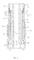
service tool 22 is representatively and schematically illustrated in enlarged scale, showing thepressure relief device 64 installed in a lower portion of thecrossover housing 48 extending downwardly within thewashpipe 50. Thepressure relief device 64 includes a generally cylindrical plug 66 received in an axial fluid passage 68. Note that one end of the passage 68 is in fluid communication with thefluid delivery flowpath 56 in the interior of thecrossover housing 48, and the opposite end of the passage is in fluid communication with thefluid return flowpath 62 in the interior of thewashpipe 50. Thus, thepressure relief device 64 is installed in a pressure-bearing wall of thecrossover housing 48. - The plug 66 carries a
circumferential seal 70 externally thereon for sealing engagement with the passage 68. Thus, thepressure relief device 64 prevents fluid communication between the fluid delivery and returnflowpaths - The plug 66 is releasably secured in the passage 68 by one or more release members 72. As depicted in FIG. 2, the release members 72 are shear members or shear pins. The shear pins 72 are sized to shear upon application of a predetermined differential pressure to the plug 66, that is, a difference in pressure between the
fluid delivery flowpath 56 and thefluid return flowpath 62. Preferably, the shear pins 72 are sized to shear at a differential pressure less than that which would cause damage to thetool 10. Of course, other types of release members, such as shear rings, shear screws, collets, etc., may be used in place of the shear pins 72 without departing from the principles of the present invention. - When the predetermined differential pressure is applied to the
pressure relief device 64, the shear pins 72 shear and the plug 66 displaces downwardly out of sealing engagement with the passage 68. Fluid flow is then permitted through the passage 68 between the fluid delivery and returnflowpaths - A ported
containment member 74 is threadedly attached to thecrossover housing 48 below the plug 66. When the plug 66 is released for displacement relative to the passage 68, thecontainment member 74 retains the plug, preventing it from dropping into thewashpipe 50. In this manner, the plug 66 may be retrieved from the well with theservice tool 22, instead of being left in theassembly 30. Of course, thepressure relief device 64 is operative without thecontainment member 74, and its use is not necessary in thetool 10. - A securement member or
ring 76 is threadedly installed in the passage 68. Thering 76 secures the shear pins 72 relative to the passage 68 and maintains engagement of the shear pins with the plug 66. Thering 76 also secures afiltering device 78 relative to the passage 68, so that the filtering device is positioned between thefluid delivery flowpath 56 and the plug 66. - As shown in FIG. 2, the
filtering device 78 is generally disc-shaped and includes a series of slots 80 formed therethrough. The slots 80 are preferably of the type known to those of ordinary skill in the art as micro-slots. These types of slots are capable of substantially preventing flow of particulate matter therethrough, while permitting fluid to flow therethrough. In this manner, theassembly 30 is not filled with particulate matter, such as proppant or gravel, when thepressure relief device 64 opens. Of course, the slots 80 may be sized as desired to exclude corresponding sizes of particulate matter, and other types of filtering devices may be utilized, such as sintered metal, wire mesh, etc., without departing from the principles of the present invention. - Referring additionally now to FIG. 3, an axial portion of the
tool 10 is representatively and schematically illustrated in an enlarged scale, showing details of thepressure relief device 36. Thepressure relief device 36 includes a generally tubularouter housing 82 having one or morefluid passages 84 formed through a sidewall portion thereof, asleeve 86 axially reciprocably and sealingly received within the housing, one ormore shear members 88 releasably securing the sleeve against displacement relative to the housing, and a generallytubular filtering device 90 radially outwardly overlying thefluid passages 84. - The
sleeve 86 carriescircumferential seals housing 82. Note that theseal 92 is carried on a smaller diameter of the sleeve as compared to that of theseal 94. Thus, there is a differential piston area formed on thesleeve 86 between the seal diameters. It will be readily appreciated that this differential piston area is exposed on one side to fluid pressure in the fluid delivery flowpath 56 (acting through thefiltering device 90 and passages 84) and on the other side to fluid pressure in thefluid return flowpath 62. - When the fluid pressure in the
fluid delivery flowpath 56 exceeds the fluid pressure in thefluid return flowpath 62 by a predetermined amount, this differential fluid pressure causes theshear members 88 to shear, thereby releasing thesleeve 86 for displacement relative to thehousing 82. As shown in FIG. 3, thesleeve 86 displaces downward, theseal 92 eventually traversing one or more of thepassages 84 and permitting fluid flow therethrough. Of course, thesleeve 86 could be easily configured to displace upward, rotate, or otherwise displace relative to thehousing 82, without departing from the principles of the present invention. - When the
sleeve 86 displaces relative to thehousing 82 and permits fluid flow through thepassages 84, the pressure differential between thefluid delivery flowpath 56 and thefluid return flowpath 62 is relieved substantially immediately. It is recognized that, with relief of the pressure differential, thesleeve 86 may not fully uncover thepassages 84, and so one or more flow ports 96 are provided in an upper portion of thesleeve 86. However, these ports 96 are not necessary in a pressure relief device constructed in accordance with the principles of the present invention. - The
filtering device 90 is representatively illustrated in FIG. 3 as a conventional wire-wrapped screen welded to the exterior of thehousing 82. Of course, other types of filtering devices, such as sintered metal, wire mesh, etc., may be used in place of thescreen 90. Alternatively, thefiltering device 90 may take the form of thepassages 84 being provided as micro-slots, the filtering device may be installed on the interior of thehousing 82, may be disposed within thepassages 84, etc. If thefiltering device 90 is installed on the interior of thehousing 82, thesleeve 86 could easily be positioned on the exterior of the housing if desired. - The
shear members 88 are shown inserted through a securement member orring 98, which is retained axially between thehousing 82 and one of thetubular sections 42 of theassembly 30. As with the shear pins 72 described above, theshear members 88 may be any form of release members, and are preferably sized to release thesleeve 86 for displacement relative to thehousing 82 at a predetermined differential pressure less than that at which damage is caused to thetool 10 or any portion thereof. Additionally, since the wellsite operation may be continued even after one of thepressure relief devices shear members 88 may be sized to release thesleeve 86 at a differential pressure the same as, greater than, or less than, that at which the shear members 72 release the plug 66 for displacement relative to thecrossover housing 48. - Note that the sidewall portion of the
housing 82 through which thepassages 84 are formed is a pressure-bearing wall of theassembly 30, exposed on its interior to fluid pressure in thefluid return flowpath 62, and on its exterior to fluid pressure in thefluid delivery flowpath 56. Therefore, when thesleeve 86 is displaced relative to thehousing 82 and fluid flow is permitted through thepassages 84, the difference in fluid pressure between the fluid delivery and returnflowpaths - Thus has been described the
tool 10 including thepressure relief devices flowpaths filtering devices fluid return flowpath 62, without departing from the principles of the present invention. Accordingly, the foregoing detailed description is to be clearly understood as being given by way of illustration and example only.
Claims (10)
- A well completion tool (10) operatively positionable within a subterranean well (12), the tool (10) comprising: a fluid delivery flowpath (56) configured for delivering fluid into the well (12); a fluid return flowpath (62) configured for returning fluid from the well (12); and a pressure relief device (36,64) in fluid communication with the fluid delivery and fluid return flowpaths (56,62), the pressure relief device (36,64) being operative to provide fluid communication between the fluid delivery and fluid return flowpaths (56,62) upon application of a first predetermined fluid pressure differential between the fluid delivery flowpath (56) and the fluid return flowpath (62).
- A well completion tool (10) according to Claim 1, wherein the pressure relief device (64) includes a plug (66) releasably secured in a passage (68) formed through a pressure-bearing wall of a housing (48) of the well completion tool (10), the wall separating the fluid delivery flowpath (56) from the fluid return flowpath (62).
- A well completion tool (10) according to Claim 2, wherein the plug (66) is releasably secured in the passage (68) by at least one shear member (72), the or each shear member (72) shearing upon application of the first fluid pressure differential.
- A well completion tool (10) according to Claim 2 or 3, further comprising a filtering device (78) disposed between the fluid delivery flowpath (56) and the plug (66).
- A well completion tool (10) according to any preceding Claim, wherein the fluid delivery flowpath (56) extends to an exterior portion of the well completion tool (10), and wherein the fluid return flowpath (62) extends to an interior portion of the well completion tool (10) separated from the exterior portion by a sidewall portion of the well completion tool (10).
- A pressure relief device (66) for use in a well tool (10) having first and second internal flowpaths (56,62), the device (66) comprising: a fluid passage (68) having opposite ends and a seal surface formed between the opposite ends, one of the opposite ends being fluid communicable with the first flowpath (56), and the other opposite ends being fluid communicable with the second flowpath (62); a plug (66) disposed at least partially within the passage (68), the plug (66) sealingly engaging the passage (68) and preventing fluid flow therethrough; and at least one release member (72) releasably securing the plug (66) relative to the passage (68), the release member (72) releasing the plug (66) for displacement relative to the passage (68) when fluid pressure in the passage (68) at one of the opposite ends exceeds fluid pressure at the other of the opposite ends by a predetermined amount.
- A pressure relief device (66) according to Claim 6, further comprising a filtering device (78) positioned between one of the passage opposite ends and the plug (66).
- A pressure relief device (36) comprising: a housing (82) having a sidewall portion separating interior and exterior portions of the housing (82); at least one fluid passage (84) formed through the sidewall portion; a sleeve (86) reciprocably and sealingly disposed relative to the sidewall portion between first and second positions, the sleeve (86) preventing fluid flow through the fluid passage (84) in the first position, and the sleeve (86) permitting fluid flow through the fluid passage (84) in the second position; and a filtering device (90), the filtering device (90) substantially preventing particulate flow through the fluid passage (84) when the sleeve (86) is in the second position.
- A method of protecting a well completion tool (10), the method comprising the steps of: sealingly engaging a plug (66) within a fluid passage (68) of the well completion tool (10), the passage (68) extending between a fluid delivery flowpath (56) and a fluid return flowpath (62); releasably securing the plug (66) within the passage (68); applying a predetermined fluid pressure differential between the fluid delivery and return flowpaths (56,62); and sealingly disengaging the plug (66) from the passage (68), thereby permitting fluid flow between the fluid delivery and return flowpaths (56,62) through the passage (68).
- A method according to Claim 9, wherein the releasably securing step is performed by installing at least one shear member (72) in the well completion tool (10).
Applications Claiming Priority (2)
| Application Number | Priority Date | Filing Date | Title |
|---|---|---|---|
| US09/090,713 US6109356A (en) | 1998-06-04 | 1998-06-04 | Well completion tool having pressure relief capability incorporated therein and associated method |
| US90713 | 1998-06-04 |
Publications (2)
| Publication Number | Publication Date |
|---|---|
| EP0962623A2 true EP0962623A2 (en) | 1999-12-08 |
| EP0962623A3 EP0962623A3 (en) | 2002-01-30 |
Family
ID=22223960
Family Applications (1)
| Application Number | Title | Priority Date | Filing Date |
|---|---|---|---|
| EP99304333A Withdrawn EP0962623A3 (en) | 1998-06-04 | 1999-06-03 | Well completion tool with fluid passages |
Country Status (2)
| Country | Link |
|---|---|
| US (1) | US6109356A (en) |
| EP (1) | EP0962623A3 (en) |
Cited By (2)
| Publication number | Priority date | Publication date | Assignee | Title |
|---|---|---|---|---|
| GB2359573B (en) * | 1998-07-22 | 2002-11-20 | Baker Hughes Inc | Apparatus and method for open hole gravel packing |
| WO2007127899A3 (en) * | 2006-04-28 | 2008-01-17 | Halliburton Energy Serv Inc | Molds and methods of forming molds associated with manufacture of rotary drill bits and other downhole tools |
Families Citing this family (8)
| Publication number | Priority date | Publication date | Assignee | Title |
|---|---|---|---|---|
| US6098710A (en) * | 1997-10-29 | 2000-08-08 | Schlumberger Technology Corporation | Method and apparatus for cementing a well |
| US6293346B1 (en) * | 1998-09-21 | 2001-09-25 | Schlumberger Technology Corporation | Method and apparatus for relieving pressure |
| US6516882B2 (en) * | 2001-07-16 | 2003-02-11 | Halliburton Energy Services, Inc. | Apparatus and method for gravel packing an interval of a wellbore |
| US7228914B2 (en) * | 2003-11-03 | 2007-06-12 | Baker Hughes Incorporated | Interventionless reservoir control systems |
| US8251150B2 (en) * | 2008-03-14 | 2012-08-28 | Superior Energy Services, L.L.C. | Radial flow valve and method |
| US8347969B2 (en) * | 2010-10-19 | 2013-01-08 | Baker Hughes Incorporated | Apparatus and method for compensating for pressure changes within an isolated annular space of a wellbore |
| US8752631B2 (en) | 2011-04-07 | 2014-06-17 | Baker Hughes Incorporated | Annular circulation valve and methods of using same |
| US8739889B2 (en) | 2011-08-01 | 2014-06-03 | Baker Hughes Incorporated | Annular pressure regulating diaphragm and methods of using same |
Citations (7)
| Publication number | Priority date | Publication date | Assignee | Title |
|---|---|---|---|---|
| US3427653A (en) * | 1965-05-04 | 1969-02-11 | Schlumberger Technology Corp | Methods for drill stem testing |
| US3515210A (en) * | 1968-06-20 | 1970-06-02 | Halliburton Co | Filter apparatus for well tool string |
| US4428428A (en) * | 1981-12-22 | 1984-01-31 | Dresser Industries, Inc. | Tool and method for gravel packing a well |
| US4633943A (en) * | 1985-07-19 | 1987-01-06 | Halliburton Company | Gravel packer |
| US5597040A (en) * | 1994-08-17 | 1997-01-28 | Western Company Of North America | Combination gravel packing/frac apparatus for use in a subterranean well bore |
| US5676208A (en) * | 1996-01-11 | 1997-10-14 | Halliburton Company | Apparatus and methods of preventing screen collapse in gravel packing operations |
| EP0903463A2 (en) * | 1997-09-18 | 1999-03-24 | Halliburton Energy Services, Inc. | Formation fracturing and gravel packing tool |
Family Cites Families (4)
| Publication number | Priority date | Publication date | Assignee | Title |
|---|---|---|---|---|
| US5137088A (en) * | 1991-04-30 | 1992-08-11 | Completion Services, Inc. | Travelling disc valve apparatus |
| US5320181A (en) * | 1992-09-28 | 1994-06-14 | Wellheads & Safety Control, Inc. | Combination check valve & back pressure valve |
| US5836395A (en) * | 1994-08-01 | 1998-11-17 | Weatherford/Lamb, Inc. | Valve for wellbore use |
| US5810084A (en) * | 1996-02-22 | 1998-09-22 | Halliburton Energy Services, Inc. | Gravel pack apparatus |
-
1998
- 1998-06-04 US US09/090,713 patent/US6109356A/en not_active Expired - Fee Related
-
1999
- 1999-06-03 EP EP99304333A patent/EP0962623A3/en not_active Withdrawn
Patent Citations (7)
| Publication number | Priority date | Publication date | Assignee | Title |
|---|---|---|---|---|
| US3427653A (en) * | 1965-05-04 | 1969-02-11 | Schlumberger Technology Corp | Methods for drill stem testing |
| US3515210A (en) * | 1968-06-20 | 1970-06-02 | Halliburton Co | Filter apparatus for well tool string |
| US4428428A (en) * | 1981-12-22 | 1984-01-31 | Dresser Industries, Inc. | Tool and method for gravel packing a well |
| US4633943A (en) * | 1985-07-19 | 1987-01-06 | Halliburton Company | Gravel packer |
| US5597040A (en) * | 1994-08-17 | 1997-01-28 | Western Company Of North America | Combination gravel packing/frac apparatus for use in a subterranean well bore |
| US5676208A (en) * | 1996-01-11 | 1997-10-14 | Halliburton Company | Apparatus and methods of preventing screen collapse in gravel packing operations |
| EP0903463A2 (en) * | 1997-09-18 | 1999-03-24 | Halliburton Energy Services, Inc. | Formation fracturing and gravel packing tool |
Cited By (4)
| Publication number | Priority date | Publication date | Assignee | Title |
|---|---|---|---|---|
| GB2359573B (en) * | 1998-07-22 | 2002-11-20 | Baker Hughes Inc | Apparatus and method for open hole gravel packing |
| WO2007127899A3 (en) * | 2006-04-28 | 2008-01-17 | Halliburton Energy Serv Inc | Molds and methods of forming molds associated with manufacture of rotary drill bits and other downhole tools |
| US7832456B2 (en) | 2006-04-28 | 2010-11-16 | Halliburton Energy Services, Inc. | Molds and methods of forming molds associated with manufacture of rotary drill bits and other downhole tools |
| US7832457B2 (en) | 2006-04-28 | 2010-11-16 | Halliburton Energy Services, Inc. | Molds, downhole tools and methods of forming |
Also Published As
| Publication number | Publication date |
|---|---|
| US6109356A (en) | 2000-08-29 |
| EP0962623A3 (en) | 2002-01-30 |
Similar Documents
| Publication | Publication Date | Title |
|---|---|---|
| US5676208A (en) | Apparatus and methods of preventing screen collapse in gravel packing operations | |
| EP0950794B1 (en) | Apparatus and method for completing a subterranean well | |
| US6176307B1 (en) | Tubing-conveyed gravel packing tool and method | |
| CA2692792C (en) | Method and apparatus for connecting shunt tubes to sand screen assemblies | |
| CA2705768C (en) | Gravel packing apparatus utilizing diverter valves | |
| US7971642B2 (en) | Gravel packing methods | |
| AU711262B2 (en) | Bidirectional disappearing plug | |
| US6732806B2 (en) | One trip expansion method and apparatus for use in a wellbore | |
| CA2372997C (en) | Single trip, multiple zone isolation, well fracturing system | |
| US7213654B2 (en) | Apparatus and methods to complete wellbore junctions | |
| US4570714A (en) | Gravel pack assembly | |
| USRE34758E (en) | Travelling disc valve apparatus | |
| EP2652238B1 (en) | Crossover joint for connecting eccentric flow paths to concentric flow paths | |
| US5285850A (en) | Well completion system for oil and gas wells | |
| EP0785337A2 (en) | Proppant containment apparatus and methods of using same | |
| US6408942B2 (en) | One-trip squeeze pack system and method of use | |
| EP0992652A2 (en) | Circulating valve for use in wellbore | |
| GB2349402A (en) | Gravel packing tool assembly with ball valve | |
| US6109356A (en) | Well completion tool having pressure relief capability incorporated therein and associated method | |
| US20060283791A1 (en) | Filter valve for fluid loss device | |
| US6053246A (en) | High flow rate formation fracturing and gravel packing tool and associated methods | |
| US5219025A (en) | Method and apparatus for gravel packing a well through a tubing string | |
| AU2017200618B2 (en) | Treatment tool for use in a subterranean well | |
| US5988271A (en) | Proppant slurry screen apparatus and methods of using same | |
| US20050034859A1 (en) | Vented gravel packing system and method of use |
Legal Events
| Date | Code | Title | Description |
|---|---|---|---|
| PUAI | Public reference made under article 153(3) epc to a published international application that has entered the european phase |
Free format text: ORIGINAL CODE: 0009012 |
|
| AK | Designated contracting states |
Kind code of ref document: A2 Designated state(s): AT BE CH CY DE DK ES FI FR GB GR IE IT LI LU MC NL PT SE Kind code of ref document: A2 Designated state(s): DE FR GB NL |
|
| AX | Request for extension of the european patent |
Free format text: AL;LT;LV;MK;RO;SI |
|
| RIN1 | Information on inventor provided before grant (corrected) |
Inventor name: FINLEY, RONNIE D. Inventor name: ECHOLS, RALPH H. |
|
| PUAL | Search report despatched |
Free format text: ORIGINAL CODE: 0009013 |
|
| AK | Designated contracting states |
Kind code of ref document: A3 Designated state(s): AT BE CH CY DE DK ES FI FR GB GR IE IT LI LU MC NL PT SE |
|
| AX | Request for extension of the european patent |
Free format text: AL;LT;LV;MK;RO;SI |
|
| 17P | Request for examination filed |
Effective date: 20020304 |
|
| 17Q | First examination report despatched |
Effective date: 20020809 |
|
| AKX | Designation fees paid |
Free format text: DE FR GB NL |
|
| STAA | Information on the status of an ep patent application or granted ep patent |
Free format text: STATUS: THE APPLICATION IS DEEMED TO BE WITHDRAWN |
|
| 18D | Application deemed to be withdrawn |
Effective date: 20031003 |