EP0953254B1 - Motion-compensated predictive image encoding and decoding - Google Patents
Motion-compensated predictive image encoding and decoding Download PDFInfo
- Publication number
- EP0953254B1 EP0953254B1 EP98949197A EP98949197A EP0953254B1 EP 0953254 B1 EP0953254 B1 EP 0953254B1 EP 98949197 A EP98949197 A EP 98949197A EP 98949197 A EP98949197 A EP 98949197A EP 0953254 B1 EP0953254 B1 EP 0953254B1
- Authority
- EP
- European Patent Office
- Prior art keywords
- motion
- objects
- mvc
- motion vectors
- block
- Prior art date
- Legal status (The legal status is an assumption and is not a legal conclusion. Google has not performed a legal analysis and makes no representation as to the accuracy of the status listed.)
- Expired - Lifetime
Links
Images
Classifications
-
- H—ELECTRICITY
- H04—ELECTRIC COMMUNICATION TECHNIQUE
- H04N—PICTORIAL COMMUNICATION, e.g. TELEVISION
- H04N19/00—Methods or arrangements for coding, decoding, compressing or decompressing digital video signals
- H04N19/50—Methods or arrangements for coding, decoding, compressing or decompressing digital video signals using predictive coding
- H04N19/503—Methods or arrangements for coding, decoding, compressing or decompressing digital video signals using predictive coding involving temporal prediction
- H04N19/51—Motion estimation or motion compensation
- H04N19/53—Multi-resolution motion estimation; Hierarchical motion estimation
-
- H—ELECTRICITY
- H04—ELECTRIC COMMUNICATION TECHNIQUE
- H04N—PICTORIAL COMMUNICATION, e.g. TELEVISION
- H04N19/00—Methods or arrangements for coding, decoding, compressing or decompressing digital video signals
- H04N19/50—Methods or arrangements for coding, decoding, compressing or decompressing digital video signals using predictive coding
- H04N19/503—Methods or arrangements for coding, decoding, compressing or decompressing digital video signals using predictive coding involving temporal prediction
- H04N19/51—Motion estimation or motion compensation
- H04N19/583—Motion compensation with overlapping blocks
Definitions
- the invention relates to motion-compensated predictive image encoding and decoding.
- a first motion-compensated predictive image encoding technique (the H.263 standard) is known in which motion vectors are estimated and used for 16*16 macro-blocks. This large macro-block size results in a relatively low number of bits for transmitting the motion data. On the other hand, the motion-compensation is rather coarse. In an extension of the H.263 standard, motion vectors are used and transmitted for smaller 8*8 blocks: more motion data, but a less coarse motion-compensation. However, the higher number of bits required for motion data results in that fewer bits are available for transmitting image data, so that the overall improvement on image quality is less than desired.
- a first aspect of the invention provides an image encoding method and device as defined in claims 1 and 3.
- a second aspect of the invention provides an image decoding method and device as defined in claims 4 and 6.
- Further aspects of the invention provide a multi-media apparatus (claim 7), an image signal display apparatus (claim 8), and an image signal (claim 9).
- Advantageous embodiments are defined in dependent claims 2 and 5.
- first motion vectors are estimated for first objects, the first motion vectors are filtered to obtain second motion vectors for second objects, the second objects being smaller than the first objects, prediction errors are generated in dependence on the second motion vectors, and the first motion vectors and the prediction errors are combined.
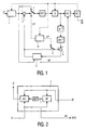
- an input video signal IV is applied to a frame skipping unit 1.
- An output of the frame skipping unit 1 is connected to a non-inverting input of a subtracter 3 and to a first input of a change-over switch 7.
- the output of the frame skipping unit 1 further supplies a current image signal to a temporal prediction unit 5.
- An inverting input of the subtracter 3 is connected to an output of the temporal prediction unit 5.
- a second input of the change-over switch 7 is connected to an output of the subtracter 3.
- An output of the change-over switch 7 is connected to a cascade arrangement of a Discrete Cosine Transformation encoder DCT and a quantizing unit Q.
- An output of the quantizing unit Q is connected to an input of a variable length encoder VLC, an output of which is connected to a buffer unit BUF that supplies an output bit-stream OB.
- the output of the quantizing unit Q is also connected to a cascade arrangement of a de-quantizing unit Q -1 and a DCT decoder DCT -1 .
- An output of the DCT decoder DCT -1 is coupled to a first input of an adder 9, a second input of which is coupled to the output of the temporal prediction unit 5 thru a switch 11.
- An output of the adder 9 supplies a reconstructed previous image to the temporal prediction unit 5.
- the temporal prediction unit 5 calculates motion vectors MV which are also encoded by the variable length encoder VLC.
- the buffer unit BUF supplies a control signal to the quantizing unit Q, and to a coding selection unit 13 which supplies an Intra-frame / Predictive encoding control signal I/P to the switches 7 and 11. If intra-frame encoding is carried out, the switches 7, 11 are in the positions shown in Fig. 1.
- the image encoder of Fig. 1 is characterized by the special construction of the temporal prediction unit 5 which will be described in more detail by means of Fig. 2.
- the temporal prediction unit 5 includes a motion estimator ME and a motion-compensated interpolator MCI which both receive the current image from the frame skipping unit 1 and the reconstructed previous image from the adder 9.
- the motion vectors MV calculated by the motion estimator ME are filtered by a motion vector post-filter MVPF before being applied to the motion-compensated interpolator MCI.
- MVPF motion vector post-filtering
- APM Advanced Prediction Mode
- MB macro-block
- Fig. 2 shows the temporal prediction unit 5 including the MVPF.
- the filtering step MVPF comprises the steps of:
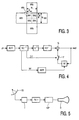
- Fig. 3 shows the block erosion of a macro-block vector MVc for a 16*16 macro-block into four block vectors MV1, MV2, MV3, MV4 for 8*8 blocks.
- Block erosion as such for use in a field-rate converter in a television receiver is known from US-A-5,148,269 (Attorneys' docket PHN 13,396). That patent does not suggest that block erosion can advantageously be used to transmit motion vectors estimated for macro-blocks, while a four times larger number of vectors is used in both the encoder and the decoder to obtain prediction errors for blocks which are four times smaller than the macro-blocks.
- Fig. 4 shows a decoder in accordance with the present invention.
- An incoming bit-stream is applied to a buffer BUFF having an output which is coupled to an input of a variable length decoder VLC -1 .
- the variable length decoder VLC -1 supplies image data to a cascade arrangement of an inverse quantizer Q -1 and a DCT decoder DCT -1 .
- An output of the DCT decoder DCT -1 is coupled to a first input of an adder 15, an output of which supplies the output signal of the decoder.
- the variable length decoder VLC -1 further supplies motion vectors MV for 16*16 macro-blocks to a motion vector post-filter MVPF to obtain motion vectors for 8*8 blocks.
- motion vectors are applied to a motion-compensation unit MC which receives the output signal of the decoder.
- An output signal of the motion-compensation unit MC is applied to a second input of the adder 15 thru a switch 17 which is controlled by an Intra-frame / Predictive encoding control signal I/P from the variable length decoder VLC -1 .
- Fig. 5 shows a image signal reception device in accordance with the present invention.
- Parts (T, Fig. 4, VSP) of this device may be part of a multi-media apparatus.
- a satellite dish SD receives a motion-compensated predictively encoded image signal in accordance with the present invention.
- the received signal is applied to a tuner T, the output signal of which is applied to the decoder of Fig. 4.
- the decoded output signal of the decoder of Fig. 4 is subjected to normal video signal processing operations VSP, the result of which is displayed on a display D.
- the motion vectors need from 13-18% of the total bit-rate in the basic H.263 standard, and 19-25 % in the H.263 standard with APM and UMV.
- UMV means Unrestricted Motion Vectors and is described in more detail in the first priority application. Basically, UMV means that the search range is quadrupled from [-16, +15.5] to [-31.5, +31.5].
- every block will be assigned its own motion vectors, while in the APM of H.263 standard not all the macro-blocks will be processed as four separate blocks. In other words, in APM is always possible that there will remain a consistent number of macro-blocks to which a motion vector is assigned, while our method always assigns one proper motion vector to every block.
- the invention relates to a low bit-rate video coding method fully compatible with H.263 standard and comprising a Motion Vector Post-Filtering (MVPF) step.
- MVPF Motion Vector Post-Filtering
- This MVPF step assigns a different motion vector to every block composing a macro-block, starting from the original motion vector of the macro-block itself.
- the temporal prediction is based on 8*8 pixels blocks instead of 16*16 macro-blocks, as actually is done when the negotiable option called Advanced Prediction Mode (APM) is used in the H.263 encoder.
- the video decoding terminal has to use the same MVPF step to produce the related block vectors.
- This method is not yet H.263 standardized, so it has to be signalled between the two terminals, via the H.245 protocol. It can be used at CIF, QCIF and SQCIF resolution.
- a method and an apparatus realizing the method, for H.263 low bit-rate video encoding and decoding stages, which inherently performs the same topics of the so called APM in terms of motion estimation and motion compensation based on 8*8 pixels blocks instead of 16*16 macro-blocks, as actually done only in H.263 encoders and decoders that use the APM.
- a method and an apparatus realizing the method which further includes a MVPF step placed in the motion estimation stage of the temporal prediction loop of the H.263 video encoder.
- a method and an apparatus realizing the method which further includes a MVPF step placed in the temporal interpolation stage of the H.263 video decoder.
- a method and an apparatus realizing the method which achieves the same (or even a superior) image quality of the APM, since the temporal prediction is based on 8*8 pixels blocks instead of 16*16 macro-blocks.
- a method and an apparatus realizing the method which achieves a lower bit-rate in comparison with APM, since only macro-block vectors are differential encoded and transmitted.
- the image quality is similar to the H.263 standard with APM.
- a method and an apparatus realizing the method which achieves a superior image quality than the H.263 standard with APM, since the bit-budget saved by encoding and transmitting only macro-block vectors is re-used for a less coarse quantization of DCT coefficients.
- the bit-rates are similar to ones achievable from the H.263 standard with APM.
- any other solution can be applied, such as a weighted averaging of adjacent macro-block vectors.
- any reference signs placed between parentheses shall not be construed as limiting the claim.
- the invention can be implemented by means of hardware comprising several distinct elements, and by means of a suitably programmed computer. In the device claim enumerating several means, several of these means can be embodied by one and the same item of hardware. While in a preferred embodiment, 16*16 macro-blocks are reduced to 8*8 blocks, a further reduction to quarter-blocks of size 4*4 is also possible, in which case the predictive encoding is based on the 4*4 quarter-blocks.
Description
- The invention relates to motion-compensated predictive image encoding and decoding.
- As set out in more detail in Sections 1-3 of the first priority application, motion-compensated predictive image encoding and decoding is well known in the art, see References [1]-[4]. A high-quality 3-Dimensional Recursive Search block matching algorithm, also described in the first priority application, is known from References [5]-[7].
- As set out in the first priority application, a first motion-compensated predictive image encoding technique (the H.263 standard) is known in which motion vectors are estimated and used for 16*16 macro-blocks. This large macro-block size results in a relatively low number of bits for transmitting the motion data. On the other hand, the motion-compensation is rather coarse. In an extension of the H.263 standard, motion vectors are used and transmitted for smaller 8*8 blocks: more motion data, but a less coarse motion-compensation. However, the higher number of bits required for motion data results in that fewer bits are available for transmitting image data, so that the overall improvement on image quality is less than desired.
- It is, inter alia, an object of the invention to provide improved motion-compensated predictive image encoding and decoding techniques. To this end, a first aspect of the invention provides an image encoding method and device as defined in
claims dependent claims 2 and 5. - In a method of motion-compensated predictive image encoding in accordance with a primary aspect of the present invention, first motion vectors are estimated for first objects, the first motion vectors are filtered to obtain second motion vectors for second objects, the second objects being smaller than the first objects, prediction errors are generated in dependence on the second motion vectors, and the first motion vectors and the prediction errors are combined.
- These and other aspects of the invention will be apparent from and elucidated with reference to the embodiments described hereinafter.
- In the drawings:
- Fig. 1 shows a basic DPCM/DCT video compression block diagram in accordance with the present invention;
- Fig. 2 shows a temporal prediction unit having a motion vector post-filter (MVPF) in accordance with the present invention;
- Fig. 3 illustrates block erosion from one vector per 16*16 macro-block to one vector for every 8*8 block;
- Fig. 4 shows a decoder block diagram in accordance with the present invention; and
- Fig. 5 shows a image signal reception device in accordance with the present invention.
- In the image encoder of Fig. 1, an input video signal IV is applied to a
frame skipping unit 1. An output of theframe skipping unit 1 is connected to a non-inverting input of asubtracter 3 and to a first input of a change-over switch 7. The output of theframe skipping unit 1 further supplies a current image signal to atemporal prediction unit 5. An inverting input of thesubtracter 3 is connected to an output of thetemporal prediction unit 5. A second input of the change-over switch 7 is connected to an output of thesubtracter 3. An output of the change-over switch 7 is connected to a cascade arrangement of a Discrete Cosine Transformation encoder DCT and a quantizing unit Q. An output of the quantizing unit Q is connected to an input of a variable length encoder VLC, an output of which is connected to a buffer unit BUF that supplies an output bit-stream OB. - The output of the quantizing unit Q is also connected to a cascade arrangement of a de-quantizing unit Q-1 and a DCT decoder DCT-1. An output of the DCT decoder DCT-1 is coupled to a first input of an
adder 9, a second input of which is coupled to the output of thetemporal prediction unit 5 thru aswitch 11. An output of theadder 9 supplies a reconstructed previous image to thetemporal prediction unit 5. Thetemporal prediction unit 5 calculates motion vectors MV which are also encoded by the variable length encoder VLC. - The buffer unit BUF supplies a control signal to the quantizing unit Q, and to a
coding selection unit 13 which supplies an Intra-frame / Predictive encoding control signal I/P to theswitches 7 and 11. If intra-frame encoding is carried out, theswitches 7, 11 are in the positions shown in Fig. 1. - In accordance with the present invention, the image encoder of Fig. 1 is characterized by the special construction of the
temporal prediction unit 5 which will be described in more detail by means of Fig. 2. - As shown in Fig. 2, the
temporal prediction unit 5 includes a motion estimator ME and a motion-compensated interpolator MCI which both receive the current image from theframe skipping unit 1 and the reconstructed previous image from theadder 9. In accordance with the present invention, the motion vectors MV calculated by the motion estimator ME are filtered by a motion vector post-filter MVPF before being applied to the motion-compensated interpolator MCI. - In this Section we will describe the real innovative part of our proposal, the motion vector post-filtering (MVPF). Preferably, we want to use the overlapped block motion-compensation based on blocks of
size 8*8, as it is actually specified in the Advanced Prediction Mode (APM) of the H.263 standard (described in more detail in the first priority application), in both the encoding and decoding terminals, while transmitting and receiving only macro-block (MB) motion vectors estimated for 16*16 macro-blocks to not increase the bit-rate. This means that both terminals have to use the same MVPF, to re-assign the MB vectors to blocks of 8*8 pixels, as performed in the motion estimation part of APM. Fig. 2 shows thetemporal prediction unit 5 including the MVPF. - Even if the MVPF should not depend on the estimation strategy, we strongly recommend to use it jointly with the motion estimator described in References [5]-[7], to obtain the best performances. Of course, there are several solutions to calculate the 8*8 block vectors, for example by a weighted averaging of the adjacent 16*16 macro-block vectors, anyway we will describe in detail only what we consider the best solution, due to the inherent features of our new motion estimator, the block erosion MVPF.
- As reported in References [1]-[4], in the H.263 standard the motion information is limited to one vector per macro-block of X*Y = 16*16 pixels. Therefore, in accordance with a preferred embodiment, the MVPF performs a block erosion to eliminate fixed block boundaries from the vector field, by re-assigning a new vector to a block of sizes (X/2)*(Y/2) = 8*8.
- If MVc = d̅(b̅ c , t) is a macro-block vector centered in b̅ c and its four adjacent macro-block vectors are given by:


- MV1 = median(MV1, MVc, MVa)
- MV2 = median(MVa, MVc, MVr)
- MV3 = median(MV1, MVc, MVb)
- MV4 = median(MVr, MVc, MVb)
- More specifically, the filtering step MVPF comprises the steps of:
- providing x and y motion vector components of a given macro-block MVc and of macro-blocks MV1, MVr, MVa, MVb adjacent to the given macro-block MVc; and
- supplying for each block MV1 of a number of blocks MV1-MV4 corresponding to the given macro-block MVc, x and y motion vector components respectively selected from the x and y motion vector components of the given macro-block MVc and from the x and y motion vector components of two blocks MV1, MVa adjacent to the block MV1.
- Fig. 3 shows the block erosion of a macro-block vector MVc for a 16*16 macro-block into four block vectors MV1, MV2, MV3, MV4 for 8*8 blocks. Block erosion as such for use in a field-rate converter in a television receiver is known from US-A-5,148,269 (Attorneys' docket PHN 13,396). That patent does not suggest that block erosion can advantageously be used to transmit motion vectors estimated for macro-blocks, while a four times larger number of vectors is used in both the encoder and the decoder to obtain prediction errors for blocks which are four times smaller than the macro-blocks.
- This solution has not been mentioned in the H.263 standard, but it is fully H.263 compatible. At the start of the multi-media communication the two terminals exchange data about their processing standard and non-standard capabilities (see Reference [4] for more details). If we assume that, during the communication set-up, both terminals declare this MVPF capability, they will easily interface with each other. Hence, the video encoder will transmit only MB vectors for 16*16 macro-blocks, while the video decoder will post-filter them in order to have a different vector for every 8*8 block. In the temporal interpolation process both terminals use the overlapped block motion compensation, as it is specified in the H.263 APM. Thanks to this method, we can achieve the same image quality as if the APM was used, but without increasing the bit-rate.
- If at least one terminal declares to have not this capability, a flag can be forced in the other terminal to switch it off.
- Fig. 4 shows a decoder in accordance with the present invention. An incoming bit-stream is applied to a buffer BUFF having an output which is coupled to an input of a variable length decoder VLC-1. The variable length decoder VLC-1 supplies image data to a cascade arrangement of an inverse quantizer Q-1 and a DCT decoder DCT-1. An output of the DCT decoder DCT-1 is coupled to a first input of an
adder 15, an output of which supplies the output signal of the decoder. The variable length decoder VLC-1 further supplies motion vectors MV for 16*16 macro-blocks to a motion vector post-filter MVPF to obtain motion vectors for 8*8 blocks. These latter motion vectors are applied to a motion-compensation unit MC which receives the output signal of the decoder. An output signal of the motion-compensation unit MC is applied to a second input of theadder 15 thru aswitch 17 which is controlled by an Intra-frame / Predictive encoding control signal I/P from the variable length decoder VLC-1. - Fig. 5 shows a image signal reception device in accordance with the present invention. Parts (T, Fig. 4, VSP) of this device may be part of a multi-media apparatus. A satellite dish SD receives a motion-compensated predictively encoded image signal in accordance with the present invention. The received signal is applied to a tuner T, the output signal of which is applied to the decoder of Fig. 4. The decoded output signal of the decoder of Fig. 4 is subjected to normal video signal processing operations VSP, the result of which is displayed on a display D.
- It is interesting to note that in one example (described in more detail in the first priority application), the motion vectors (macro-block information) need from 13-18% of the total bit-rate in the basic H.263 standard, and 19-25 % in the H.263 standard with APM and UMV. UMV means Unrestricted Motion Vectors and is described in more detail in the first priority application. Basically, UMV means that the search range is quadrupled from [-16, +15.5] to [-31.5, +31.5].
- Thanks to our method, we can use the difference between these amounts of bits for relaxing the DCT coefficients quantization instead of encoding the motion vectors information related to blocks, so that we achieve higher sharpness pictures than actual H.263 standard image encoders with APM, without increasing the bit-rates.
- On the other hand, if the DCT coefficients quantization is not relaxed, we can encode and transmit "typical H.263 plus APM quality" pictures, while reducing the bit-rate because of no block motion information transmission, thus increasing the channel efficiency.
- Finally, in our method every block will be assigned its own motion vectors, while in the APM of H.263 standard not all the macro-blocks will be processed as four separate blocks. In other words, in APM is always possible that there will remain a consistent number of macro-blocks to which a motion vector is assigned, while our method always assigns one proper motion vector to every block.
- A primary aspect of the invention can be summarized as follows. The invention relates to a low bit-rate video coding method fully compatible with H.263 standard and comprising a Motion Vector Post-Filtering (MVPF) step. This MVPF step assigns a different motion vector to every block composing a macro-block, starting from the original motion vector of the macro-block itself. In this way the temporal prediction is based on 8*8 pixels blocks instead of 16*16 macro-blocks, as actually is done when the negotiable option called Advanced Prediction Mode (APM) is used in the H.263 encoder. The video decoding terminal has to use the same MVPF step to produce the related block vectors.
- Furthermore, since only macro-block vectors are differentially encoded (in a variable length fashion) and transmitted, a considerable bit-rate reduction is also achieved, in comparison with APM.
- This method is not yet H.263 standardized, so it has to be signalled between the two terminals, via the H.245 protocol. It can be used at CIF, QCIF and SQCIF resolution.
- The following salient features of the invention are noteworthy.
- A method and an apparatus realizing the method, for H.263 low bit-rate video encoding and decoding stages, which inherently performs the same topics of the so called APM in terms of motion estimation and motion compensation based on 8*8 pixels blocks instead of 16*16 macro-blocks, as actually done only in H.263 encoders and decoders that use the APM.
- A method and an apparatus realizing the method which further includes a MVPF step placed in the motion estimation stage of the temporal prediction loop of the H.263 video encoder.
- A method and an apparatus realizing the method which further includes a MVPF step placed in the temporal interpolation stage of the H.263 video decoder.
- A method and an apparatus realizing the method which achieves the same (or even a superior) image quality of the APM, since the temporal prediction is based on 8*8 pixels blocks instead of 16*16 macro-blocks.
- A method and an apparatus realizing the method which achieves a lower bit-rate in comparison with APM, since only macro-block vectors are differential encoded and transmitted. The image quality is similar to the H.263 standard with APM.
- A method and an apparatus realizing the method which achieves a superior image quality than the H.263 standard with APM, since the bit-budget saved by encoding and transmitting only macro-block vectors is re-used for a less coarse quantization of DCT coefficients. The bit-rates are similar to ones achievable from the H.263 standard with APM.
- A method and an apparatus realizing the method where the MVPF is a block erosion stage, when the motion estimation is calculated on macro-blocks of H.263 standard dimensions (16*16 pixels). Anyway any other solution can be applied, such as a weighted averaging of adjacent macro-block vectors.
- It should be noted that the above-mentioned embodiments illustrate rather than limit the invention, and that those skilled in the art will be able to design many alternative embodiments without departing from the scope of the appended claims. In the claims, any reference signs placed between parentheses shall not be construed as limiting the claim. The invention can be implemented by means of hardware comprising several distinct elements, and by means of a suitably programmed computer. In the device claim enumerating several means, several of these means can be embodied by one and the same item of hardware. While in a preferred embodiment, 16*16 macro-blocks are reduced to 8*8 blocks, a further reduction to quarter-blocks of size 4*4 is also possible, in which case the predictive encoding is based on the 4*4 quarter-blocks.
-
- [1] ITU-T DRAFT Recommendation H.263, Video coding for low bit rate communication, 2 May 1996.
- [2] K. Rijkse, "ITU standardisation of very low bit rate video coding algorithms", Signal Processing: Image Communication 7,1995, pp 553-565.
- [3] ITU-T DRAFT Recommendation H.261, Video codec for audio-visual services at px64 kbits, March 1993.
- [4] ITU-T DRAFT Recommendation H.245, Control protocol for multimedia communications, 27 November 1995.
- [5] G. de Haan, P.W.A.C. Biezen, H. Huijgen, O. A. Ojo, "True motion estimation with 3-D recursive search block matching", IEEE Trans. Circuits and Systems for Video Technology, Vol. 3, October 1993, pp. 368-379.
- [6] G. de Haan, P.W.A.C. Biezen, "Sub-pixel motion estimation with 3-D recursive search block-matching", Signal Processing: Image Communication 6 (1995), pp. 485-498.
- [7] P. Lippens, B. De Loore, G. de Haan, P. Eeckhout, H. Huijgen, A. Loning, B. McSweeney, M. Verstraelen, B. Pham, J. Kettenis, "A video signal processor for motion-compensated field-rate up-conversion in consumer television", IEEE Journal of Solid-state Circuits, Vol. 31, no. 11, November 1996, pp. 1762-1769.
Claims (9)
- A method of motion-compensated predictive image encoding, comprising the steps of:estimating (ME) first motion vectors (MVc, MV1, MVr, MVa, MVb) for first objects (16*16);filtering (MVPF) each of said first motion vectors (MVc, MV1, MVr, MVa, MVb) to obtain second motion vectors (MV1, MV2, MV3, MV4 for second objects (8*8), said second objects (8*8) being smaller than said first objects (16*16) and corresponding to a given-first object (16*16).generating (3) prediction errors in dependence on said second motion vectors (MV1, MV2, MV3, MV4) only; andencoding (VLC) said first motion vectors (MVc, MV1, MVr, MVa, MVb) and said prediction errors.
- A method as claimed in claim 1, wherein said first objects (16*16) are macro-blocks, said second objects (8*8) are blocks, and said filtering step (MVPF) comprises the steps of:providing x and y motion vector components of a given macro-block (MVc) and of macro-blocks (MV1, MVr, MVa, MVb) adjacent to said given macro-block (MVc); andsupplying for each block (MV1) of a number of blocks (MV1-MV4) corresponding to said given macro-block (MVc), x and y motion vector components respectively selected from said x and y motion vector components of said given macro-block (MVc) and from the x and y motion vector components of two blocks (MV1, MVa) adjacent to said block (MV1).
- A device for motion-compensated predictive image encoding, comprising:means for estimating (ME) first motion vectors (MVc, MV1, MVr, MVa, MVb) for first objects (16*16);means for filtering (MVPF) each of said first motion vectors (MVc, MV1, MVr, MVa, MVb) to obtain second motion vectors (MV1, MV2, MV3, MV4) for second objects (8*8), said second objects (8*8) being smaller than said first objects (16*16) and corresponding to a given first object (16*16);means for generating (3) prediction errors in dependence on said second motion vectors (MV1, MV2, MV3, MV4) only; andmeans for encoding (VLC) said first motion vectors (MVc, MV1, MVr, MVa, MVb) and said prediction errors.
- A method of motion-compensated predictive decoding, comprising the steps of:generating (VLC-1) first motion vectors (MVc, MV1, MVr, MVa, MVb) and prediction errors from an input bit-stream, said first motion vectors (MVc, MV1, MVr, MVa, MVb) relating to first objects (16*16) and said prediction errors relating to second objects (8*8) only;filtering (MVPF) each of said first motion vectors (MVc, MV1, MVr, MVa, MVb) to obtain second motion vectors (MV1, MV2, MV3, MV4) for second objects (8*8), said second objects (8*8) being smaller than said first objects (16* 16) and corresponding to a given first object (16*16); andgenerating (15, MC) an output signal in dependence on said prediction errors and said second motion vectors (MV1, MV2, MV3, MV4).
- A method as claimed in claim 4, wherein said first objects (16*16) are macro-blocks, said second objects (8*8) are blocks, and said filtering step (MVPF) comprises the steps of:providing x and y motion vector components of a given macro-block (MVc) and of macro-blocks (MV1, MVr, MVa, MVb) adjacent to said given macro-block (MVc); andsupplying for each block (MV1) of a number of blocks (MV1-MV4) corresponding to said given macro-block (MVc), x and y motion vector components respectively selected from said x and y motion vector components of said given macro-block (MVc) and from the x and y motion vector components of two blocks (MV1, MVa) adjacent to said block (MV 1).
- A device for motion-compensated predictive decoding, comprising:means for generating (VLC-1) first motion vectors (MVc, MV1, MVr, MVa, MVb) and prediction errors from an input bit-stream, said first motion vectors (MVc, MV1, MVr, MVa, MVb) relating to first objects (16*16) and said prediction errors relating to second objects (8*8) only;means for filtering (MVPF) said first motion vectors (MVc, MV1, MVr, MVa, MVb) to obtain second motion vectors (MV1, MV2, MV3, MV4) for second objects (8*8), said second objects (8*8) being smaller than said first objects (16*16) and corresponding to a given first object (16*16); andmeans for generating (15, MC) an output signal in dependence on said prediction errors and said second motion vectors (MV1, MV2, MV3, MV4).
- A multi-media apparatus, comprising:means (T) for receiving a motion-compensated predictively encoded image signal; anda motion-compensated predictive decoding device as claimed in claim 6 for generating a decoded image signal.
- An image signal display apparatus, comprising:means (T) for receiving a motion-compensated predictively encoded image signal;a motion-compensated predictive decoding device as claimed in claim 6 for generating a decoded image signal; andmeans (D) for displaying said decoded image signal.
- A motion-compensated predictively encoded image signal, comprising:motion vectors (MVc, MV1, MVr, MVa, MVb) relating to first objects (16*16); andprediction errors relating to second objects (8*8), said second objects (8*8) being smaller than said first objects (16*16) and corresponding to a given first object (16*16), wherein said prediction errors depend on motion vectors for said second objects (8*8).
Priority Applications (1)
| Application Number | Priority Date | Filing Date | Title |
|---|---|---|---|
| EP98949197A EP0953254B1 (en) | 1997-11-17 | 1998-11-02 | Motion-compensated predictive image encoding and decoding |
Applications Claiming Priority (6)
| Application Number | Priority Date | Filing Date | Title |
|---|---|---|---|
| EP97402763 | 1997-11-17 | ||
| EP97402763 | 1997-11-17 | ||
| EP98200461 | 1998-02-13 | ||
| EP98200461 | 1998-02-13 | ||
| EP98949197A EP0953254B1 (en) | 1997-11-17 | 1998-11-02 | Motion-compensated predictive image encoding and decoding |
| PCT/IB1998/001757 WO1999026417A2 (en) | 1997-11-17 | 1998-11-02 | Motion-compensated predictive image encoding and decoding |
Publications (2)
| Publication Number | Publication Date |
|---|---|
| EP0953254A2 EP0953254A2 (en) | 1999-11-03 |
| EP0953254B1 true EP0953254B1 (en) | 2006-06-14 |
Family
ID=26147920
Family Applications (1)
| Application Number | Title | Priority Date | Filing Date |
|---|---|---|---|
| EP98949197A Expired - Lifetime EP0953254B1 (en) | 1997-11-17 | 1998-11-02 | Motion-compensated predictive image encoding and decoding |
Country Status (6)
| Country | Link |
|---|---|
| US (1) | US20020031272A1 (en) |
| EP (1) | EP0953254B1 (en) |
| JP (1) | JP2001508633A (en) |
| KR (1) | KR100600419B1 (en) |
| DE (1) | DE69834902T2 (en) |
| WO (1) | WO1999026417A2 (en) |
Families Citing this family (59)
| Publication number | Priority date | Publication date | Assignee | Title |
|---|---|---|---|---|
| US6473460B1 (en) * | 2000-03-31 | 2002-10-29 | Matsushita Electric Industrial Co., Ltd. | Method and apparatus for calculating motion vectors |
| US6810081B2 (en) * | 2000-12-15 | 2004-10-26 | Koninklijke Philips Electronics N.V. | Method for improving accuracy of block based motion compensation |
| US8824553B2 (en) | 2003-05-12 | 2014-09-02 | Google Inc. | Video compression method |
| JP2008543154A (en) * | 2005-05-25 | 2008-11-27 | エヌエックスピー ビー ヴィ | Macroblock multiple-instance video decoder encoded with progressive and interlaced scanning. |
| KR101369224B1 (en) * | 2007-03-28 | 2014-03-05 | 삼성전자주식회사 | Method and apparatus for Video encoding and decoding using motion compensation filtering |
| JP2008311781A (en) * | 2007-06-12 | 2008-12-25 | Ntt Docomo Inc | Motion picture encoder, motion picture decoder, motion picture encoding method, motion picture decoding method, motion picture encoding program and motion picture decoding program |
| JP2012502552A (en) * | 2008-09-04 | 2012-01-26 | トムソン ライセンシング | Method and apparatus for predictive refinement using implicit motion prediction |
| US8325796B2 (en) | 2008-09-11 | 2012-12-04 | Google Inc. | System and method for video coding using adaptive segmentation |
| US8385404B2 (en) | 2008-09-11 | 2013-02-26 | Google Inc. | System and method for video encoding using constructed reference frame |
| US8326075B2 (en) | 2008-09-11 | 2012-12-04 | Google Inc. | System and method for video encoding using adaptive loop filter |
| US8718142B2 (en) * | 2009-03-04 | 2014-05-06 | Entropic Communications, Inc. | System and method for frame rate conversion that utilizes motion estimation and motion compensated temporal interpolation employing embedded video compression |
| US9532059B2 (en) | 2010-10-05 | 2016-12-27 | Google Technology Holdings LLC | Method and apparatus for spatial scalability for video coding |
| US8611415B1 (en) | 2010-11-15 | 2013-12-17 | Google Inc. | System and method for coding using improved motion estimation |
| US8891626B1 (en) | 2011-04-05 | 2014-11-18 | Google Inc. | Center of motion for encoding motion fields |
| US8693547B2 (en) | 2011-04-06 | 2014-04-08 | Google Inc. | Apparatus and method for coding using motion vector segmentation |
| US9154799B2 (en) | 2011-04-07 | 2015-10-06 | Google Inc. | Encoding and decoding motion via image segmentation |
| US8780971B1 (en) | 2011-04-07 | 2014-07-15 | Google, Inc. | System and method of encoding using selectable loop filters |
| US8780996B2 (en) | 2011-04-07 | 2014-07-15 | Google, Inc. | System and method for encoding and decoding video data |
| US8781004B1 (en) | 2011-04-07 | 2014-07-15 | Google Inc. | System and method for encoding video using variable loop filter |
| US8638854B1 (en) | 2011-04-07 | 2014-01-28 | Google Inc. | Apparatus and method for creating an alternate reference frame for video compression using maximal differences |
| US8804819B1 (en) | 2011-04-19 | 2014-08-12 | Google Inc. | Method and apparatus for encoding video using data frequency |
| US9749638B1 (en) | 2011-04-28 | 2017-08-29 | Google Inc. | Method and apparatus for encoding video with dynamic quality improvement |
| US8705620B1 (en) | 2011-04-28 | 2014-04-22 | Google Inc. | Method and apparatus for encoding anchor frame by encoding features using layers |
| US8989256B2 (en) | 2011-05-25 | 2015-03-24 | Google Inc. | Method and apparatus for using segmentation-based coding of prediction information |
| WO2013006386A1 (en) | 2011-07-01 | 2013-01-10 | General Instrument Corporation | Motion vector prediction design simplification |
| US8885706B2 (en) | 2011-09-16 | 2014-11-11 | Google Inc. | Apparatus and methodology for a video codec system with noise reduction capability |
| CN104041041B (en) | 2011-11-04 | 2017-09-01 | 谷歌技术控股有限责任公司 | Motion vector scaling for the vectorial grid of nonuniform motion |
| US9247257B1 (en) | 2011-11-30 | 2016-01-26 | Google Inc. | Segmentation based entropy encoding and decoding |
| US9014265B1 (en) | 2011-12-29 | 2015-04-21 | Google Inc. | Video coding using edge detection and block partitioning for intra prediction |
| US8908767B1 (en) | 2012-02-09 | 2014-12-09 | Google Inc. | Temporal motion vector prediction |
| US9262670B2 (en) | 2012-02-10 | 2016-02-16 | Google Inc. | Adaptive region of interest |
| US9094681B1 (en) | 2012-02-28 | 2015-07-28 | Google Inc. | Adaptive segmentation |
| US9131073B1 (en) | 2012-03-02 | 2015-09-08 | Google Inc. | Motion estimation aided noise reduction |
| US9609341B1 (en) | 2012-04-23 | 2017-03-28 | Google Inc. | Video data encoding and decoding using reference picture lists |
| WO2013162980A2 (en) | 2012-04-23 | 2013-10-31 | Google Inc. | Managing multi-reference picture buffers for video data coding |
| US9172970B1 (en) | 2012-05-29 | 2015-10-27 | Google Inc. | Inter frame candidate selection for a video encoder |
| US9014266B1 (en) | 2012-06-05 | 2015-04-21 | Google Inc. | Decimated sliding windows for multi-reference prediction in video coding |
| US11317101B2 (en) | 2012-06-12 | 2022-04-26 | Google Inc. | Inter frame candidate selection for a video encoder |
| US9344729B1 (en) | 2012-07-11 | 2016-05-17 | Google Inc. | Selective prediction signal filtering |
| US9332276B1 (en) | 2012-08-09 | 2016-05-03 | Google Inc. | Variable-sized super block based direct prediction mode |
| US9380298B1 (en) | 2012-08-10 | 2016-06-28 | Google Inc. | Object-based intra-prediction |
| US9288484B1 (en) | 2012-08-30 | 2016-03-15 | Google Inc. | Sparse coding dictionary priming |
| US9407915B2 (en) | 2012-10-08 | 2016-08-02 | Google Inc. | Lossless video coding with sub-frame level optimal quantization values |
| US9210432B2 (en) | 2012-10-08 | 2015-12-08 | Google Inc. | Lossless inter-frame video coding |
| US9503746B2 (en) | 2012-10-08 | 2016-11-22 | Google Inc. | Determine reference motion vectors |
| US9369732B2 (en) | 2012-10-08 | 2016-06-14 | Google Inc. | Lossless intra-prediction video coding |
| US9485515B2 (en) | 2013-08-23 | 2016-11-01 | Google Inc. | Video coding using reference motion vectors |
| US9756346B2 (en) | 2012-10-08 | 2017-09-05 | Google Inc. | Edge-selective intra coding |
| US9225979B1 (en) | 2013-01-30 | 2015-12-29 | Google Inc. | Remote access encoding |
| US9210424B1 (en) | 2013-02-28 | 2015-12-08 | Google Inc. | Adaptive prediction block size in video coding |
| US9300906B2 (en) | 2013-03-29 | 2016-03-29 | Google Inc. | Pull frame interpolation |
| US9756331B1 (en) | 2013-06-17 | 2017-09-05 | Google Inc. | Advance coded reference prediction |
| US9313493B1 (en) | 2013-06-27 | 2016-04-12 | Google Inc. | Advanced motion estimation |
| US9392272B1 (en) | 2014-06-02 | 2016-07-12 | Google Inc. | Video coding using adaptive source variance based partitioning |
| US9578324B1 (en) | 2014-06-27 | 2017-02-21 | Google Inc. | Video coding using statistical-based spatially differentiated partitioning |
| US9286653B2 (en) | 2014-08-06 | 2016-03-15 | Google Inc. | System and method for increasing the bit depth of images |
| US9153017B1 (en) | 2014-08-15 | 2015-10-06 | Google Inc. | System and method for optimized chroma subsampling |
| US10102613B2 (en) | 2014-09-25 | 2018-10-16 | Google Llc | Frequency-domain denoising |
| US9807416B2 (en) | 2015-09-21 | 2017-10-31 | Google Inc. | Low-latency two-pass video coding |
Family Cites Families (3)
| Publication number | Priority date | Publication date | Assignee | Title |
|---|---|---|---|---|
| EP0466981B1 (en) * | 1990-07-20 | 1997-02-26 | Koninklijke Philips Electronics N.V. | Motion vector processing device |
| EP0648052B1 (en) * | 1993-09-08 | 2000-03-01 | THOMSON multimedia | Method and apparatus for motion estimation using block matching |
| US5539469A (en) * | 1994-12-30 | 1996-07-23 | Daewoo Electronics Co., Ltd. | Apparatus for determining motion vectors through the use of an adaptive median filtering technique |
-
1998
- 1998-11-02 DE DE69834902T patent/DE69834902T2/en not_active Expired - Lifetime
- 1998-11-02 WO PCT/IB1998/001757 patent/WO1999026417A2/en active IP Right Grant
- 1998-11-02 KR KR1019997006499A patent/KR100600419B1/en not_active IP Right Cessation
- 1998-11-02 JP JP52799399A patent/JP2001508633A/en not_active Abandoned
- 1998-11-02 EP EP98949197A patent/EP0953254B1/en not_active Expired - Lifetime
- 1998-11-16 US US09/192,674 patent/US20020031272A1/en not_active Abandoned
Also Published As
| Publication number | Publication date |
|---|---|
| WO1999026417A2 (en) | 1999-05-27 |
| EP0953254A2 (en) | 1999-11-03 |
| DE69834902T2 (en) | 2007-02-01 |
| KR100600419B1 (en) | 2006-07-13 |
| WO1999026417A3 (en) | 1999-07-22 |
| KR20000070271A (en) | 2000-11-25 |
| DE69834902D1 (en) | 2006-07-27 |
| JP2001508633A (en) | 2001-06-26 |
| US20020031272A1 (en) | 2002-03-14 |
Similar Documents
| Publication | Publication Date | Title |
|---|---|---|
| EP0953254B1 (en) | Motion-compensated predictive image encoding and decoding | |
| US7379501B2 (en) | Differential coding of interpolation filters | |
| Schafer et al. | Digital video coding standards and their role in video communications | |
| US7555043B2 (en) | Image processing apparatus and method | |
| US5376968A (en) | Adaptive compression of digital video data using different modes such as PCM and DPCM | |
| EP0538667B1 (en) | Adaptive motion compensation using a plurality of motion compensators | |
| EP0564597B1 (en) | Systems and methods for coding even fields of interlaced video sequences | |
| EP0683957B1 (en) | Method and apparatus for transcoding a digitally compressed high definition television bitstream to a standard definition television bitstream | |
| EP0951184A1 (en) | Method for converting digital signal and apparatus for converting digital signal | |
| EP1309199A2 (en) | Motion compensation for interlaced digital video signals | |
| EP0953253B1 (en) | Motion-compensated predictive image encoding and decoding | |
| JP2001238218A (en) | Signal converting apparatus and method | |
| EP1006723A2 (en) | Apparatus and method for video frame rate conversion | |
| US20080137741A1 (en) | Video transcoding | |
| KR100945826B1 (en) | Image information decoding method and decoder | |
| US20020094030A1 (en) | Apparatus and method of transcoding image data in digital TV | |
| JPH07212761A (en) | Hierarchical coder and hierarchical decoder | |
| Ericsson | Motion-compensated hybrid coding at 50 kb/s | |
| JP3166835B2 (en) | Method and apparatus for highly efficient coding of moving images | |
| Chen et al. | 263 (including H. 263+) and other ITU-T video coding standards | |
| Turaga et al. | ITU-T Video Coding Standards | |
| Puri | Tsuhan Chen Carnegie Mellon University, Pittsburgh, Pennsylvania Gary J. Sullivan Picture Tel Corporation, Andover, Massachusetts | |
| Bhaskaran et al. | Video Teleconferencing Standards | |
| WO1997002703A1 (en) | Virtual broadband technology |
Legal Events
| Date | Code | Title | Description |
|---|---|---|---|
| PUAI | Public reference made under article 153(3) epc to a published international application that has entered the european phase |
Free format text: ORIGINAL CODE: 0009012 |
|
| 17P | Request for examination filed |
Effective date: 19990817 |
|
| AK | Designated contracting states |
Kind code of ref document: A2 Designated state(s): DE FR GB SE |
|
| 17Q | First examination report despatched |
Effective date: 20040503 |
|
| GRAP | Despatch of communication of intention to grant a patent |
Free format text: ORIGINAL CODE: EPIDOSNIGR1 |
|
| GRAS | Grant fee paid |
Free format text: ORIGINAL CODE: EPIDOSNIGR3 |
|
| GRAA | (expected) grant |
Free format text: ORIGINAL CODE: 0009210 |
|
| AK | Designated contracting states |
Kind code of ref document: B1 Designated state(s): DE FR GB SE |
|
| REG | Reference to a national code |
Ref country code: GB Ref legal event code: FG4D |
|
| REF | Corresponds to: |
Ref document number: 69834902 Country of ref document: DE Date of ref document: 20060727 Kind code of ref document: P |
|
| PG25 | Lapsed in a contracting state [announced via postgrant information from national office to epo] |
Ref country code: SE Free format text: LAPSE BECAUSE OF FAILURE TO SUBMIT A TRANSLATION OF THE DESCRIPTION OR TO PAY THE FEE WITHIN THE PRESCRIBED TIME-LIMIT Effective date: 20060914 |
|
| ET | Fr: translation filed | ||
| PLBE | No opposition filed within time limit |
Free format text: ORIGINAL CODE: 0009261 |
|
| STAA | Information on the status of an ep patent application or granted ep patent |
Free format text: STATUS: NO OPPOSITION FILED WITHIN TIME LIMIT |
|
| 26N | No opposition filed |
Effective date: 20070315 |
|
| REG | Reference to a national code |
Ref country code: GB Ref legal event code: 732E Free format text: REGISTERED BETWEEN 20090305 AND 20090311 |
|
| PGFP | Annual fee paid to national office [announced via postgrant information from national office to epo] |
Ref country code: FR Payment date: 20081118 Year of fee payment: 11 |
|
| REG | Reference to a national code |
Ref country code: FR Ref legal event code: ST Effective date: 20100730 |
|
| PG25 | Lapsed in a contracting state [announced via postgrant information from national office to epo] |
Ref country code: FR Free format text: LAPSE BECAUSE OF NON-PAYMENT OF DUE FEES Effective date: 20091130 |
|
| REG | Reference to a national code |
Ref country code: GB Ref legal event code: 732E Free format text: REGISTERED BETWEEN 20120628 AND 20120704 |
|
| REG | Reference to a national code |
Ref country code: DE Ref legal event code: R082 Ref document number: 69834902 Country of ref document: DE Representative=s name: PATENTANWAELTE BRESSEL UND PARTNER MBB, DE Effective date: 20121213 Ref country code: DE Ref legal event code: R082 Ref document number: 69834902 Country of ref document: DE Representative=s name: PATENTANWAELTE BRESSEL UND PARTNER, DE Effective date: 20121213 Ref country code: DE Ref legal event code: R081 Ref document number: 69834902 Country of ref document: DE Owner name: PENDRAGON WIRELESS LLC (A NEVADA MANAGED LIMIT, US Free format text: FORMER OWNER: IPG ELECTRONICS 503 LTD., ST. PETER PORT, GUERNSEY, GB Effective date: 20121213 Ref country code: DE Ref legal event code: R081 Ref document number: 69834902 Country of ref document: DE Owner name: PENDRAGON WIRELESS LLC (A NEVADA MANAGED LIMIT, US Free format text: FORMER OWNER: IPG ELECTRONICS 503 LTD., ST. PETER PORT, GB Effective date: 20121213 |
|
| PGFP | Annual fee paid to national office [announced via postgrant information from national office to epo] |
Ref country code: DE Payment date: 20131121 Year of fee payment: 16 Ref country code: GB Payment date: 20131120 Year of fee payment: 16 |
|
| REG | Reference to a national code |
Ref country code: DE Ref legal event code: R119 Ref document number: 69834902 Country of ref document: DE |
|
| GBPC | Gb: european patent ceased through non-payment of renewal fee |
Effective date: 20141102 |
|
| PG25 | Lapsed in a contracting state [announced via postgrant information from national office to epo] |
Ref country code: GB Free format text: LAPSE BECAUSE OF NON-PAYMENT OF DUE FEES Effective date: 20141102 Ref country code: DE Free format text: LAPSE BECAUSE OF NON-PAYMENT OF DUE FEES Effective date: 20150602 |