EP0952663B1 - Driving circuit for oscillatory actuator - Google Patents
Driving circuit for oscillatory actuator Download PDFInfo
- Publication number
- EP0952663B1 EP0952663B1 EP99201222A EP99201222A EP0952663B1 EP 0952663 B1 EP0952663 B1 EP 0952663B1 EP 99201222 A EP99201222 A EP 99201222A EP 99201222 A EP99201222 A EP 99201222A EP 0952663 B1 EP0952663 B1 EP 0952663B1
- Authority
- EP
- European Patent Office
- Prior art keywords
- electromagnet
- coil
- voltage
- driving circuit
- moving element
- Prior art date
- Legal status (The legal status is an assumption and is not a legal conclusion. Google has not performed a legal analysis and makes no representation as to the accuracy of the status listed.)
- Expired - Lifetime
Links
Images


Classifications
-
- H—ELECTRICITY
- H02—GENERATION; CONVERSION OR DISTRIBUTION OF ELECTRIC POWER
- H02P—CONTROL OR REGULATION OF ELECTRIC MOTORS, ELECTRIC GENERATORS OR DYNAMO-ELECTRIC CONVERTERS; CONTROLLING TRANSFORMERS, REACTORS OR CHOKE COILS
- H02P25/00—Arrangements or methods for the control of AC motors characterised by the kind of AC motor or by structural details
- H02P25/02—Arrangements or methods for the control of AC motors characterised by the kind of AC motor or by structural details characterised by the kind of motor
- H02P25/032—Reciprocating, oscillating or vibrating motors
Definitions
- This invention relates to an actuator driving circuit and, more particularly, to a driving circuit for oscillatory a.ctuator.having.a moving element provided for a reciprocating movement.
- an oscillatory actuator which comprises a stator consisting of an electromagnet, and a moving element having a permanent magnet and supported by a spring as a resetting means.
- the oscillatory actuator of the kind referred to is constituted such that the electromagnet forming the stator is provided, for example, with three stator magnetic poles arranged linearly at regular intervals, and a central one of the stator poles is excited to be differently polarized from other two stator poles by an exciting current flowing through a stator coil.
- the permanent magnet provided to the moving element is disposed movable in the direction in which the stator poles are arranged, and is magnetized to have two poles in the movable direction, and a distance between centers of these two magnetic poles of the permanent magnet is made substantially equal to a distance between centers of a pair of adjacent ones of the stator poles.
- the moving element is supported to be resettable substantially to the central position of the movable range.
- the moving element When in the oscillatory actuator of this arrangement an alternating voltage of a rectangular waveform is applied to the stator coil, the moving element is caused to be moved to one side by means of a magnetic force between the stator poles and the permanent magnet during an excitation to one polarity of the stator coil, whereas the moving element is moved to the other side by the magnetic force between the stator poles and the permanent magnet during an excitation to the other polarity of the stator coil.
- a resetting force to the center position of the movable range is applied to the moving element by a resilient force of the foregoing spring. That is, the moving element is enabled to perform a reciprocating movement by the application of the alternating voltage.
- Such oscillatory actuator realizes reciprocating type electric shaver with an inner movable blade coupled to the moving element of the actuator, utilizing the reciprocating movement of the moving element.
- Known art of this kind has been disclosed in, for example, U.S. Patents No. 5,176,311 to Levne et al . and No. 5,589,749 to Davidson et al .
- EP-A-0 652 632 discloses a power supply for vibrating compressors having an inverter for converting direct current (d-c) into alternating current (a-c).
- GB-A-1 411 335 relates to dry shavers driven by an electric motor, and in particular to a control means for said drive motor.
- the voltage application to the stator coil should preferably be controlled in its timing in accordance with the position of the moving element. That is, the driving energy can be reduced by exciting the stator coil in synchronism with the natural frequency of the moving element to attain a resonating state. Accordingly, such sensor as a photointerrupter is provided for sensing that the moving element has passed through a specific position, and the timing of the voltage application to the stator coil is controlled.
- the provision of such sensor causes a circuit to be required for controlling the sensor and processing outputs of the sensor, and a problem to arise that the actuator is enlarged in dimensions as a whole.
- the foregoing application of the rectangular waveform alternating voltage to the stator coil causes a current containing much of higher harmonic components to flow to the stator coil.
- a comparison of efficiency of the application of a sinusoidal voltage to the stator coil with that of the application of the rectangular waveform voltage to the stator coil has revealed that the application of the rectangular waveform voltage is inferior, and this voltage application results in such problem that, when employed in battery-powered electric appliances and equipments, the battery has to be exchanged or recharged remarkably frequently.
- An object of the present invention is to provide a driving circuit for oscillatory actuator which is capable of eliminating the foregoing problems, synchronizing the timing of the voltage application to the electromagnet coil with the reciprocating movement of the moving element, still minimizing the dimensions with any position sensor made unnecessary, and rendering the driving efficiency not to be deteriorated even upon fluctuation of the load with an application of the sinusoidal voltage or current to the electromagnet coil.
- this object can be attained by means of a driving circuit for the oscillatory actuator wherein at least one of the stator and moving element is provided with an electromagnet, means is provided for resetting the moving element to a predetermined position when the electromagnet is not excited and the moving element is caused to perform its reciprocating movement due to variation in the magnetic force acting between the electromagnet and the moving element upon application of the alternating voltage to the electromagnet, characterized in that the applied voltage to the coil of the electromagnet is generated by a self-excitation oscillation with a positive feedback of a counter electromotive force occurring in the coil of the electromagnet in correspondence to the reciprocating movement of the moving element.
- FIG. 1 an embodiment according to the present invention is shown, in which such amplifier as an operational amplifier 11 is connected at an output terminal through a driving circuit 12 to an end of a capacitor 13.
- the other end of this capacitor 13 is connected to a non-inverted input terminal of the operational amplifier 11 and also to an end of a stator coil 1 forming a linear actuator.
- a resistor 14 is inserted between the other end of the stator coil 1 and an inverted input terminal of the operational amplifier 11, and a variable resistor 15 is inserted between the output terminal and the inverted input terminal of the operational amplifier 11.
- the driving circuit 12 is formed with a pair of transistors Q1 and Q2 in a complementary connection and is provided for boosting an output voltage of the operational amplifier 11 to a source voltage ( ⁇ V), and a voltage capable of driving the linear actuator is thereby obtained. While it is assumed here that a battery or batteries will be used as the power source, any other power source may be used.
- the capacitor 13 is set in accordance with the natural frequency of the moving element of the linear actuator, and a series resonance circuit formed by the stator coil 1 and capacitor 13 is set to have a resonance frequency conforming to the natural frequency of the moving element of the linear actuator. At this time, the circuit shown in FIG. 1 can be represented by such equivalent circuit as shown in FIG.
- the linear actuator is regarded as being a series circuit of a DC resistor R of the stator coil 1, and inductance L of the stator coil 1 and a counter electromotive force E, and the circuit other than the capacitor 13 is forming a control circuit 10.
- a power source Vs for applying a source voltage to the driving circuit 12 is provided to the control circuit 10, the counter electromotive force E is caused to be generated by an intersection of magnetic flux of the permanent magnet with respect to the stator coil 1 upon movement of the moving element in the linear actuator, and a sinusoidal signal corresponding to the frequency of the moving element in the linear actuator is to be generated.
- the signal is input to the non-inverted input terminal of the operational amplifier 11, the signal is subjected to a positive feedback amplification, and the circuit shown in FIG. 1 is to perform a self-oscillation. Since the frequency of this oscillation relies on the frequency of mechanical system of the linear actuator, an excitation voltage of a frequency corresponding to any fluctuation in the load of the linear actuator is applied to the stator coil 1. Further, as the linear actuator itself is forming a required resonance system for the oscillation, the resonance system can be omitted in contrast to an event where the applied voltage to the stator coil 1 is generated with a separate circuit for the self-oscillation (that is, in the event of a separately-excited oscillation), and required parts number can be reduced by that extent.
- a driving force acting on the moving element is to be proportional to a square of a current flowing to the stator coil 1.
- the resonance frequency of the series resonance circuit of the stator coil 1 and capacitor 13 is made to coincide with the natural frequency of the moving element of the linear actuator, so that, in an event of non-load and when the excitation voltage applied to the stator coil 1 is in conformity with the natural frequency of the linear actuator, a composite reactance of an inductance component of the stator coil 1 and a capacitance component of the capacitor 13 will be substantially zero.
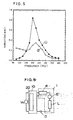
- the linear actuator is employed as a driving source of an electric shaver and shows such natural frequency as shown by a curve "1" of FIG. 3 in no-load state (about 200 Hz), the natural frequency is caused to be deviated remarkably as shown, for example, by a curve "2" of FIG. 3 upon application of a load with beard hair being shaved.
- FIG. 6 of the present invention employs a starting circuit 20 added to the control circuit 10. While in the circuit of FIG. 6 the driving circuit 12 is also disposed on output side of the operational amplifier 11, the driving circuit 12 is omitted from FIG. 6.
- the starting circuit 20 comprises, as shown in FIG.
- a one-shot multivibrator 23 connected through a diode 21 and a capacitor 22 to the non-inverted input terminal of the operational amplifier 11, and a series circuit of a capacitor 25 and a resistor 26 connected across both terminals of the power source Vs through a switch 24 and, at a junction point between the capacitor 25 and resistor 26, to a trigger terminal CK of the one-shot multivibrator 23.
- the power source Vs is provided for outputting the voltage of ⁇ V and has a grounding terminal at a middle point.
- a phototransistor 27a forming a light receiving element of a photocoupler 27 is connected in parallel, and a light emitting diode 27 a forming a light emitting element of the photocoupler 27 is connected through a current limitting resistor 28 and a rectifying diode 29, to the output terminal of the operational amplifier 11.
- a smoothing capacitor 30 is connected between a junction point of the resistor 28 to the diode 29, and the grounding terminal of the power source Vs.
- resistors 31 and 32 are respectively connected. Instead of direct connection of the junction point between the stator coil 1 and the capacitor 13 to the non-inverted input terminal of the operational amplifier 11, a resistor 16 is inserted between them.
- the circuit shown in FIG. 7 operates as follows.
- the capacitor 25 is charged through the resistor 26 so that, as in FIG. 8 (d), a voltage across the capacitor 25 rises with time.
- the one-shot multivibrator 23 employed here is to be triggered at a rising of trigger signal so that, as the voltage across the capacitor 25 reaches at a time T1 a trigger voltage Vt of the one-shot multivibrator 23, a pulse signal of a constant pulse width is output from the multivibrator 23. That is, at the time T1, such pulse voltage as in FIG. 8(c) grows as a voltage across the resistor 32.
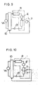
- FIG. 9 employs a detection coil 7 in the linear actuator for detecting an induced electromotive force in the stator coil 1, and the operation of the linear actuator is controlled by feeding an output of this detection coil 7 back to the control circuit.
- the detection coil 7 is provided separately from the electromagnet 3. In this case, the detection coil 7 may be disposed adjacent to the electromagnet 3 or even as wound on the electromagnet 3 as in FIG. 10.
- the movement of the moving element is detected by means of the induced electromotive force, and the voltage applied to the stator coil is fed back in correspondence to the induced electromotive force, so that the operation is enabled to be equivalent to the case of feeding back the counter electromotive force.
- the periodic voltage is eventually applied to the stator coil 1.
- Other arrangements and operation are the same as those in the embodiment of FIGS. 1 to 5.
- FIGS. 11 (a) and 11(b) Another embodiment according to the present invention as shown in FIGS. 11 (a) and 11(b) is arranged for rendering an applied voltage or current to the stator coil 1 to be equivalent to the sinusoidal voltage or current by applying to the stator coil 1 a pulse voltage of a pulse width varying with time. That is, the pulse width is so controlled that the pulse voltage in the average value in respective minute periods into which the time is equally divided will be equal to corresponding part of the sinusoidal voltage.
- This type of control can be easily realized by an application of a technique known as a PWM (pulse width modulation) control. Further, the applied voltage (of curves "1" in FIG. 11) is enabled to be adjusted to be relatively high as in FIG. 11 (a) and to be relatively low as in FIG. 11 (b). The excitation current (of curves "2" in FIG. 11) can be also made sinusoidal.
- the linear actuator is made applicable to the feedback control.
- the same effect can be attained even when the capacitor 13 is omitted.
- Other arrangements and operation are the same as those in the embodiments of FIGS. 1 to 5.
- an actuator driving circuit useful specifically when employed in acoustic equipments.
- a counter electromotive force E is provided from the stator coil 1 of the oscillatory actuator through a positive feedback path to the operational amplifier 11, and an output of the operational amplifier 11 is provided back to the stator coil 1.
- a voltage substantially of the same level as the source voltage ( ⁇ V) can be continuously provided continuously to the stator coil 1, with any fluctuation minimized.
- FIG. 13 shows a practical example of the embodiment of FIG. 12, in which the driving circuit is combined with a bridge-type audio amplifier AD which per se has been known.
- the oscillatory actuator can be employed in a speaker system, such that a unique arrangement causes a positive feedback output denoted by Vo to be provided in response to the counter electromotive force.
- the output denoted by Vol is subjected to a negative feedback so as to adjust a gain of the operational amplifier 11.
- an optimumly set voltage V DD can be provided.
- the operational amplifier 11 is connected to a single side DC power source a bias voltage is sent to the non-inverted input terminal of the amplifier, and a bipolar oscilllation can be realized. Further, the arrangement is so made that output of the operational amplifier 11 triggers a MOS type switching element to have a driving current provided whereby a threshold voltage can be effectively lowered, and the oscillatory voltage of the actuator upon starting can be increased to be twice to four times as large.
- the output terminal of one operational amplifier 11A is connected to the non-inverted input terminal of the other operational amplifier 11B, to have a driving input provided to P-channel of MOS type switching elements, whereby a rise of the oscillation can be made further easier.
- the self-oscillation is performed with the positive feedback of the counter electromotive force grown in the coil of the electromagnet, so that the periodic voltage synchronizing with the mechanical oscillation of the oscillatory actuator can be applied to the electromagnet, and it is enabled to drive the oscillatory actuator at a high efficiency.
- the timing of voltage application to the coil of the electromagnet is synchronised with the reciprocating movement of the moving element, any separate sensor for detecting the position of the moving element is made unnecessary, so as to be advantageous in that the circuit arrangement is simplified and can be thus minimized in dimensions.
- the self-oscillation stabilizes the oscillation, so that there arise various advantages such that the driving efficiency is rendered less deteriorated, the applied voltage or current to the actuator coil can be made sinusoidal to render the effect to be higher, and so on, as will be readily appreciated.
Landscapes
- Engineering & Computer Science (AREA)
- Power Engineering (AREA)
- Reciprocating, Oscillating Or Vibrating Motors (AREA)
- Control Of Linear Motors (AREA)
- General Electrical Machinery Utilizing Piezoelectricity, Electrostriction Or Magnetostriction (AREA)
Description
- This invention relates to an actuator driving circuit and, more particularly, to a driving circuit for oscillatory a.ctuator.having.a moving element provided for a reciprocating movement.
- There has been provided an oscillatory actuator which comprises a stator consisting of an electromagnet, and a moving element having a permanent magnet and supported by a spring as a resetting means. The oscillatory actuator of the kind referred to is constituted such that the electromagnet forming the stator is provided, for example, with three stator magnetic poles arranged linearly at regular intervals, and a central one of the stator poles is excited to be differently polarized from other two stator poles by an exciting current flowing through a stator coil. The permanent magnet provided to the moving element is disposed movable in the direction in which the stator poles are arranged, and is magnetized to have two poles in the movable direction, and a distance between centers of these two magnetic poles of the permanent magnet is made substantially equal to a distance between centers of a pair of adjacent ones of the stator poles. The moving element is supported to be resettable substantially to the central position of the movable range.
- When in the oscillatory actuator of this arrangement an alternating voltage of a rectangular waveform is applied to the stator coil, the moving element is caused to be moved to one side by means of a magnetic force between the stator poles and the permanent magnet during an excitation to one polarity of the stator coil, whereas the moving element is moved to the other side by the magnetic force between the stator poles and the permanent magnet during an excitation to the other polarity of the stator coil. In a period in which no voltage is applied to the stator coil, a resetting force to the center position of the movable range is applied to the moving element by a resilient force of the foregoing spring. That is, the moving element is enabled to perform a reciprocating movement by the application of the alternating voltage. Such oscillatory actuator realizes reciprocating type electric shaver with an inner movable blade coupled to the moving element of the actuator, utilizing the reciprocating movement of the moving element. Known art of this kind has been disclosed in, for example,
U.S. Patents No. 5,176,311 to Levne et al . and No.5,589,749 to Davidson et al . -
EP-A-0 652 632 discloses a power supply for vibrating compressors having an inverter for converting direct current (d-c) into alternating current (a-c). -
GB-A-1 411 335 - When, in this case, a load to be driven by the moving element fluctuates to cause oscillatory cycle of the moving element to be varied, there arises a risk that, even where measures for controlling operational timing with a sensor employed, the oscillatory cycle loses at least temporarily or continuously its synchronism with the excitation voltage applied to the stator coil so as to be in a malfunction. In the event of such asynchronism of the oscillatory cycle of the moving element with the excitation voltage, even the application of such periodic voltage as sinusoidal voltage to the stator coil causes a feedback to take place from the stator to the moving element for supplying an energy in a direction of deceleration, and there arises a problem that an evergy loss is eventually caused so as to have the driving efficiency deteriorated. In keeping the reciprocating movement of the moving element continued in the linear actuator of the foregoing arrangement, further, the voltage application to the stator coil should preferably be controlled in its timing in accordance with the position of the moving element. That is, the driving energy can be reduced by exciting the stator coil in synchronism with the natural frequency of the moving element to attain a resonating state. Accordingly, such sensor as a photointerrupter is provided for sensing that the moving element has passed through a specific position, and the timing of the voltage application to the stator coil is controlled. However, the provision of such sensor causes a circuit to be required for controlling the sensor and processing outputs of the sensor, and a problem to arise that the actuator is enlarged in dimensions as a whole.
- Further, the foregoing application of the rectangular waveform alternating voltage to the stator coil causes a current containing much of higher harmonic components to flow to the stator coil. A comparison of efficiency of the application of a sinusoidal voltage to the stator coil with that of the application of the rectangular waveform voltage to the stator coil has revealed that the application of the rectangular waveform voltage is inferior, and this voltage application results in such problem that, when employed in battery-powered electric appliances and equipments, the battery has to be exchanged or recharged remarkably frequently.
- An object of the present invention is to provide a driving circuit for oscillatory actuator which is capable of eliminating the foregoing problems, synchronizing the timing of the voltage application to the electromagnet coil with the reciprocating movement of the moving element, still minimizing the dimensions with any position sensor made unnecessary, and rendering the driving efficiency not to be deteriorated even upon fluctuation of the load with an application of the sinusoidal voltage or current to the electromagnet coil.
- According to the present invention, this object can be attained by means of a driving circuit for the oscillatory actuator wherein at least one of the stator and moving element is provided with an electromagnet, means is provided for resetting the moving element to a predetermined position when the electromagnet is not excited and the moving element is caused to perform its reciprocating movement due to variation in the magnetic force acting between the electromagnet and the moving element upon application of the alternating voltage to the electromagnet, characterized in that the applied voltage to the coil of the electromagnet is generated by a self-excitation oscillation with a positive feedback of a counter electromotive force occurring in the coil of the electromagnet in correspondence to the reciprocating movement of the moving element.
- Other objects and advantages of the present invention shall become clear as the description of the invention advances as detailed with reference to embodiments shown in accompanying drawings.
-
- FIGURE 1 is a circuit diagram of an embodiment of the driving circuit for the actuator according to the present invention;
- FIG. 2 is an explanatory diagram for the principle of the driving circuit of FIG. 1;
- FIGS. 3 to 5 are explanatory diagrams for the operation of the driving circuit in FIG. 1, respectively;
- FIG. 6 is a schematic circuit diagram showing another embodiment of the present invention;
- FIG. 7 is a detailed circuit diagram of the embodiment of FIG. 6;
- FIGS. 8(a) to 8(e) are waveform diagrams explanatory for the operation of the embodiment of FIG. 6;
- FIG. 9 is a schematic circuit diagram showing an aspect of another embodiment of the present invention;
- FIG. 10 is schematic circuit diagram showing another aspect of the embodiment of FIG. 9;
- FIGS. 11(a) and 11(b) are waveform diagrams explanatory for the operation in another embodiment of the present invention;
- FIG. 12 is a schematic diagram showing an arrangement in another embodiment of the present invention;
- FIG. 13 is a circuit diagram showing a practical example of the embodiment of FIG. 12; and
- FIGS. 14 and 15 are circuit diagrams respectively showing still another embodiment of the present invention.
- While the present invention shall now be described with reference to the respective embodiments shown in the drawings, it should be appreciated that the intention is not to limit the present invention only to these embodiments but rather to include all alterations, modifications and equivalent arrangements possible within the scope of appended claims.
- The present invention will now be described in the followings with reference to the embodiments. While the embodiments according to the present invention are described in the followings with reference to the oscillatory actuator, in particular the linear actuator in which the electromagnet and permanent magnet are combined for rectilinear reciprocating motion, it is possible to apply the technical idea of the present invention also to other types of the oscillatory actuators.
- In FIG. 1, an embodiment according to the present invention is shown, in which such amplifier as an
operational amplifier 11 is connected at an output terminal through adriving circuit 12 to an end of acapacitor 13. The other end of thiscapacitor 13 is connected to a non-inverted input terminal of theoperational amplifier 11 and also to an end of astator coil 1 forming a linear actuator. Aresistor 14 is inserted between the other end of thestator coil 1 and an inverted input terminal of theoperational amplifier 11, and avariable resistor 15 is inserted between the output terminal and the inverted input terminal of theoperational amplifier 11. - The
driving circuit 12 is formed with a pair of transistors Q1 and Q2 in a complementary connection and is provided for boosting an output voltage of theoperational amplifier 11 to a source voltage (±V), and a voltage capable of driving the linear actuator is thereby obtained. While it is assumed here that a battery or batteries will be used as the power source, any other power source may be used. Thecapacitor 13 is set in accordance with the natural frequency of the moving element of the linear actuator, and a series resonance circuit formed by thestator coil 1 andcapacitor 13 is set to have a resonance frequency conforming to the natural frequency of the moving element of the linear actuator. At this time, the circuit shown in FIG. 1 can be represented by such equivalent circuit as shown in FIG. 2, in which the linear actuator is regarded as being a series circuit of a DC resistor R of thestator coil 1, and inductance L of thestator coil 1 and a counter electromotive force E, and the circuit other than thecapacitor 13 is forming acontrol circuit 10. A power source Vs for applying a source voltage to thedriving circuit 12 is provided to thecontrol circuit 10, the counter electromotive force E is caused to be generated by an intersection of magnetic flux of the permanent magnet with respect to thestator coil 1 upon movement of the moving element in the linear actuator, and a sinusoidal signal corresponding to the frequency of the moving element in the linear actuator is to be generated. As this signal is input to the non-inverted input terminal of theoperational amplifier 11, the signal is subjected to a positive feedback amplification, and the circuit shown in FIG. 1 is to perform a self-oscillation. Since the frequency of this oscillation relies on the frequency of mechanical system of the linear actuator, an excitation voltage of a frequency corresponding to any fluctuation in the load of the linear actuator is applied to thestator coil 1. Further, as the linear actuator itself is forming a required resonance system for the oscillation, the resonance system can be omitted in contrast to an event where the applied voltage to thestator coil 1 is generated with a separate circuit for the self-oscillation (that is, in the event of a separately-excited oscillation), and required parts number can be reduced by that extent. - Since in the foregoing circuit arrangement a momentary position of the moving element in the linear actuator and a momentary value of the excitation voltage for the
stator coil 1 coincide with each other, a driving force acting on the moving element is to be proportional to a square of a current flowing to thestator coil 1. Further, as the resonance frequency of the series resonance circuit of thestator coil 1 andcapacitor 13 is made to coincide with the natural frequency of the moving element of the linear actuator, so that, in an event of non-load and when the excitation voltage applied to thestator coil 1 is in conformity with the natural frequency of the linear actuator, a composite reactance of an inductance component of thestator coil 1 and a capacitance component of thecapacitor 13 will be substantially zero. As a result, a circuit impedance can be in a state close only to a resistance component. Accordingly, it is enabled that a large current is caused to flow to thestator coil 1 and the linear actuator can be efficiently driven. With the foregoing provision of thecapacitor 13, therefore, the driving force acting on the moving element can be made larger than in an aspect where no capacitor is employed. Provided here that the linear actuator is employed as a driving source of an electric shaver and shows such natural frequency as shown by a curve "1" of FIG. 3 in no-load state (about 200 Hz), the natural frequency is caused to be deviated remarkably as shown, for example, by a curve "2" of FIG. 3 upon application of a load with beard hair being shaved. Since in the present embodiment the resonance state is intented to be maintained with the provision of thecapacitor 13, it is possible to enlarge the current value adjacent to the natural frequency as shown by a curve "1" in FIG. 4 in contrast to an aspect of nocapacitor 13 as shown by a curve "2" in FIG. 4, and the driving force acting on the moving element become twice as larger as shown by a curve "1" in FIG. 5, as that where no capacitor is used as shown by a curve "2" in FIG 5. That is, any efficiency deterioration or malfunction can be effectively prevented from occurring even upon fluctuation in the load. - While in the above embodiment the arrangement is so made as to start the operation of the linear actuator with the connection to the power source, another embodiment shown in FIG. 6 of the present invention employs a
starting circuit 20 added to thecontrol circuit 10. While in the circuit of FIG. 6 thedriving circuit 12 is also disposed on output side of theoperational amplifier 11, thedriving circuit 12 is omitted from FIG. 6. Thestarting circuit 20 comprises, as shown in FIG. 7, a one-shot multivibrator 23 connected through adiode 21 and a capacitor 22 to the non-inverted input terminal of theoperational amplifier 11, and a series circuit of acapacitor 25 and aresistor 26 connected across both terminals of the power source Vs through aswitch 24 and, at a junction point between thecapacitor 25 andresistor 26, to a trigger terminal CK of the one-shot multivibrator 23. The power source Vs is provided for outputting the voltage of ±V and has a grounding terminal at a middle point. Across thecapacitor 25, further, a phototransistor 27a forming a light receiving element of aphotocoupler 27 is connected in parallel, and a light emitting diode 27 a forming a light emitting element of thephotocoupler 27 is connected through acurrent limitting resistor 28 and a rectifyingdiode 29, to the output terminal of theoperational amplifier 11. Between a junction point of theresistor 28 to thediode 29, and the grounding terminal of the power source Vs, a smoothingcapacitor 30 is connected. Between each of both ends of thediode 21 and the grounding terminal of the power source Vs,resistors 31 and 32 are respectively connected. Instead of direct connection of the junction point between thestator coil 1 and thecapacitor 13 to the non-inverted input terminal of theoperational amplifier 11, aresistor 16 is inserted between them. - Now, the circuit shown in FIG. 7 operates as follows. When the circuit is connected to the power source Vs with the
switch 24 made ON at a time T0 of FIG. 8, thecapacitor 25 is charged through theresistor 26 so that, as in FIG. 8 (d), a voltage across thecapacitor 25 rises with time. The one-shot multivibrator 23 employed here is to be triggered at a rising of trigger signal so that, as the voltage across thecapacitor 25 reaches at a time T1 a trigger voltage Vt of the one-shot multivibrator 23, a pulse signal of a constant pulse width is output from themultivibrator 23. That is, at the time T1, such pulse voltage as in FIG. 8(c) grows as a voltage across theresistor 32. With this pulse voltage input to theoperational amplifier 11, such voltage as in FIG. 8(b) is provide as an output of theoperational amplifier 11, and such voltage as in FIG. 8(a) is applied to thestator coil 1. With this voltage applied the linear actuator starts its operation to generate a counter electromotive force. - Even upon termination of this input from the one
shot multivibrator 23 to theoperational amplifier 11, the counter electromotive force of the linear actuator is fed back to theoperational amplifier 11, and the operating state of the linear actuator is thereby maintained. That is, such periodic voltage as sinusoidal voltage can be applied to thestator coil 1 so that the exciting voltage or current to thestator coil 1 converges to a state of causing the linear actuator to stably operate. - In an event where the output voltage can be obtained continuously from the
operational amplifier 11, a voltage across thecapacitor 30 rises as in FIG. 8 (e), and, at a time T2, this voltage reaches a state of being retained substantially at a constant voltage. As the voltage across thecapacitor 30 rises, a light output of the light-emitting diode of thephotocoupler 27 increases, thephototransistor 27b gradually increases its conduction, whereby a charge in thecapacitor 25 is caused to be discharged through thephototransistor 27b, and the voltage applied to the trigger terminal CK of the one-shot multivibrator 23 can be maintained to be substantially zero during the operation of the linear actuator. Once the linear actuator stops due to some cause or theswitch 24 once turned OFF is again turned ON, thecapacitor 25 is charged again, and the foregoing operation is repeated. - In the embodiment of FIGS. 6 to 8, as has been described, the start of the operation of the actuator is made easier by the provision of the starting
circuit 20, and the linear actuator is enabled to re-start automatically even when the linear actuator is once stopped for some reason, without requiring theswitch 24 to be turned ON. Other arrangements and operation of this embodiment are the same as those in the embodiment of FIGS. 1 to 5. - While in the respective embodiments of FIGS. 1 to 5 and FIGS. 6 to 8 the arrangement is so made as to maintain the operation of the linear actuator with the feedback of the counter electromotive force occurring in the
stator coil 1 of the linear actuator, another embodiment of FIG. 9 according to the present invention employs a detection coil 7 in the linear actuator for detecting an induced electromotive force in thestator coil 1, and the operation of the linear actuator is controlled by feeding an output of this detection coil 7 back to the control circuit. As shown in FIG. 9, the detection coil 7 is provided separately from the electromagnet 3. In this case, the detection coil 7 may be disposed adjacent to the electromagnet 3 or even as wound on the electromagnet 3 as in FIG. 10. - In the foregoing embodiment of FIG. 9, the movement of the moving element is detected by means of the induced electromotive force, and the voltage applied to the stator coil is fed back in correspondence to the induced electromotive force, so that the operation is enabled to be equivalent to the case of feeding back the counter electromotive force. Also, similar to the case of the feedback of the counter electromotive force, the periodic voltage is eventually applied to the
stator coil 1. Other arrangements and operation are the same as those in the embodiment of FIGS. 1 to 5. - While in the respective foregoing embodiments the arrangement is made so that the periodic, continuous waveform voltage will be applied to the
stator coil 1, such various waveforms as rectangular, sinusoidal and the like waveforms can be obtained with a proper circuit arrangement employed. Another embodiment according to the present invention as shown in FIGS. 11 (a) and 11(b) is arranged for rendering an applied voltage or current to thestator coil 1 to be equivalent to the sinusoidal voltage or current by applying to the stator coil 1 a pulse voltage of a pulse width varying with time. That is, the pulse width is so controlled that the pulse voltage in the average value in respective minute periods into which the time is equally divided will be equal to corresponding part of the sinusoidal voltage. This type of control can be easily realized by an application of a technique known as a PWM (pulse width modulation) control. Further, the applied voltage (of curves "1" in FIG. 11) is enabled to be adjusted to be relatively high as in FIG. 11 (a) and to be relatively low as in FIG. 11 (b). The excitation current (of curves "2" in FIG. 11) can be also made sinusoidal. - Further, with a provision of such output detecting coil 7 as in the embodiment of FIG. 9, the linear actuator is made applicable to the feedback control. The same effect can be attained even when the
capacitor 13 is omitted. Other arrangements and operation are the same as those in the embodiments of FIGS. 1 to 5. - In another embodiment shown in FIG. 12, an actuator driving circuit useful specifically when employed in acoustic equipments. In this case, a counter electromotive force E is provided from the
stator coil 1 of the oscillatory actuator through a positive feedback path to theoperational amplifier 11, and an output of theoperational amplifier 11 is provided back to thestator coil 1. With this arrangement, a voltage substantially of the same level as the source voltage (±V) can be continuously provided continuously to thestator coil 1, with any fluctuation minimized. - More specifically, FIG. 13 shows a practical example of the embodiment of FIG. 12, in which the driving circuit is combined with a bridge-type audio amplifier AD which per se has been known. The oscillatory actuator can be employed in a speaker system, such that a unique arrangement causes a positive feedback output denoted by Vo to be provided in response to the counter electromotive force. At this time, the output denoted by Vol is subjected to a negative feedback so as to adjust a gain of the
operational amplifier 11. With this arrangement, an optimumly set voltage VDD can be provided. - In another embodiment shown in FIG. 14, the
operational amplifier 11 is connected to a single side DC power source a bias voltage is sent to the non-inverted input terminal of the amplifier, and a bipolar oscilllation can be realized. Further, the arrangement is so made that output of theoperational amplifier 11 triggers a MOS type switching element to have a driving current provided whereby a threshold voltage can be effectively lowered, and the oscillatory voltage of the actuator upon starting can be increased to be twice to four times as large. - In still another embodiment of the present invention as shown in FIG. 15, in contrast to the embodiment of FIG. 14, the output terminal of one operational amplifier 11A is connected to the non-inverted input terminal of the other
operational amplifier 11B, to have a driving input provided to P-channel of MOS type switching elements, whereby a rise of the oscillation can be made further easier. - While in the foregoing description the operational amplifier has been mainly referred to, the invention is not limited only to the use thereof but may similarly employ any other amplifier so long as the same function is attainable.
- According to the present invention as has been described, the self-oscillation is performed with the positive feedback of the counter electromotive force grown in the coil of the electromagnet, so that the periodic voltage synchronizing with the mechanical oscillation of the oscillatory actuator can be applied to the electromagnet, and it is enabled to drive the oscillatory actuator at a high efficiency. Further, while the timing of voltage application to the coil of the electromagnet is synchronised with the reciprocating movement of the moving element, any separate sensor for detecting the position of the moving element is made unnecessary, so as to be advantageous in that the circuit arrangement is simplified and can be thus minimized in dimensions. Further, the self-oscillation stabilizes the oscillation, so that there arise various advantages such that the driving efficiency is rendered less deteriorated, the applied voltage or current to the actuator coil can be made sinusoidal to render the effect to be higher, and so on, as will be readily appreciated.
Claims (20)
- A driving circuit for oscillatory actuator in which
at least one of a stator (2) and a moving element (4) includes an electromagnet (3), means (6) is provided for resetting the moving element to a predetermined position in non-exciting state of the electromagnet, and
the moving element is caused to perform its reciprocating movement due to variation in the magnetic force acting between the electromagnet and the moving element upon application of an alternating voltage to the electromagnet,
a control circuit (10) is provided for generating a voltage applied to the coil of the electromagnet
characterized in that
said control circuit provides said voltage generated through a positive feedback of a counter-electromotive force occurring in the coil of the electromagnet in correspondence to the reciprocating movement of the moving element, and
a capacitor (13) is inserted between the control circuit and the coil of the electromagnet to form a series resonance circuit together with the coil, said resonance circuit resonating at a resonance frequency coincide with a natural frequency of the moving element to give said voltage applied to said coil of the electromagnet. - The driving circuit according to claim 1 wherein
the control circuit applies to the coil of the electromagnet a driving voltage immediately after connection of the circuit to a power source (Vs). - The driving circuit according to claim 1 wherein
the control circuit comprises
an amplifier (11) performing a positive feedback of a counter electromotive force occurring in the coil of the electromagnet in correspondence to the reciprocating movement of the moving element, and a
variable resistor (15) for adjusting the amplification of the amplifier to adjust the amplitude of the applied voltage to the coil of the electromagnet. - The driving circuit according to claim 3 wherein
the control circuit further comprises a one-shot multivibrator (23) generating a pulse signal immediately after connection of the circuit to a power source (Vs), the pulse signal being provided to the amplifier to have a starting voltage generated and applied to the coil of the electromagnet. - The driving circuit according to claim 1 wherein
the control circuit generates the applied voltage to the coil of the electromagnet with a voltage of discontinuous waveform in an equivalent manner. - The driving circuit according to claim 5 wherein
the voltage of discontinuous waveform is a rectangular wave voltage having a pulse width sufficiently smaller than a cycle of the reciprocating movement of the moving element and varying with time. - The driving circuit according to claim 5 wherein
the applied voltage is of a sinusoidal waveform. - The driving circuit according to claim 1 wherein
a detection coil (7) is provided for detecting magnetic flux generated by the coil of the electromagnet, and
the control circuit generates the voltage applied to the coil of the electromagnet through a self-excitation oscillation with a positive feedback of an induced electromotive force occurring in the coil of the electromagnet in correspondence to the reciprocating movement of the moving element. - The driving circuit according to claim 8 wherein
the detection coil is prepared separately from the electromagnet and is disposed adjacent to the electromagnet. - The driving circuit according to claim 8 wherein
the detection coil is wound on the electromagnet. - The driving circuit according to claim 1 wherein
the control circuit applies to the coil of the electromagnet a driving voltage immediately after connection of the circuit to a power source. - The driving circuit according to claim 1 wherein
the control circuit comprises an operational amplifier (11) performing a positive feedback of a counter electromotive force occurring in the coil of the electromagnet in correspondence to the reciprocating movement of the moving element, and
a variable resistor (15) for adjusting the amplification of the operational amplifier to adjust the amplitude of the applied voltage to the coil of the electromagnet. - The driving circuit according to claim 1 wherein
the circuit further comprises a one-shot multivibrator (23) for generating a pulse signal immediately after connection of the circuit to a power source (Vs), the pulse signal being provided to an operational amplifier for causing a starting voltage to be generated and applied to the coil of the electromagnet. - The driving circuit according to claim 1 wherein
the circuit is provided for use in acoustic devices and equipments. - The driving circuit according to claim 14 wherein
the control circuit generates a voltage applied to the coil of the electromagnet through a self-oscillation with a positive feedback of a counter electromotive force occurring in the coil of the electromagnet in correspondence to the reciprocating movement of the moving element. - The driving circuit according to claim 15 wherein
a detection coil is provided for detecting magnetic flux generated by the coil of the electromagnet, and
the control circuit generates the voltage applied to the coil of the electromagnet through a self-excitation oscillation with a positive feedback of an induced electromotive force occurring in the coil of the electromagnet in correspondence to the reciprocating movement of the moving element. - The driving circuit according to claim 15 wherein
the detection coil is prepared separately from the electromagnet and is disposed adjacent to the electromagnet. - The driving circuit according to claim 15 wherein
the detection coil is wound on the electromagnet. - The driving circuit according to claim 14 wherein
the control circuit applies to the coil of the electromagnet a driving voltage immediately after connection of the circuit to a power source. - The driving circuit according to claim 1 wherein
said means (6) for resetting the moving element to said predetermined position in the non-exciting state of the electromagnet has an elasticity, and
said control circuit applies said voltage of a sinusoidal excited voltage to the coil of said electromagnet.
Applications Claiming Priority (2)
| Application Number | Priority Date | Filing Date | Title |
|---|---|---|---|
| JP11372398 | 1998-04-23 | ||
| JP11372398 | 1998-04-23 |
Publications (3)
| Publication Number | Publication Date |
|---|---|
| EP0952663A2 EP0952663A2 (en) | 1999-10-27 |
| EP0952663A3 EP0952663A3 (en) | 2000-04-26 |
| EP0952663B1 true EP0952663B1 (en) | 2007-11-21 |
Family
ID=14619519
Family Applications (1)
| Application Number | Title | Priority Date | Filing Date |
|---|---|---|---|
| EP99201222A Expired - Lifetime EP0952663B1 (en) | 1998-04-23 | 1999-04-22 | Driving circuit for oscillatory actuator |
Country Status (4)
| Country | Link |
|---|---|
| US (1) | US6133701A (en) |
| EP (1) | EP0952663B1 (en) |
| DE (1) | DE69937587T2 (en) |
| HK (1) | HK1023233A1 (en) |
Families Citing this family (32)
| Publication number | Priority date | Publication date | Assignee | Title |
|---|---|---|---|---|
| DE19859622A1 (en) * | 1998-12-23 | 2000-07-06 | Braun Gmbh | Drive device for oscillating electrical products for personal use, in particular dry shavers |
| US6388417B1 (en) | 1999-12-06 | 2002-05-14 | Macrosonix Corporation | High stability dynamic force motor |
| DE19958888A1 (en) * | 1999-12-07 | 2001-06-13 | Sheng Chih Sheng | Bidirectional electro magnetic linear actuator for valve, has armature located in exciting coil with permanent magnets for providing holding force at end sections |
| JP3750455B2 (en) * | 2000-01-14 | 2006-03-01 | 松下電工株式会社 | Self-excited oscillation circuit |
| JP2002128261A (en) * | 2000-10-23 | 2002-05-09 | Ykk Corp | Method for controlling electromagnetic parts feeder and device thereof |
| EP1233505A1 (en) * | 2001-02-20 | 2002-08-21 | Sony International (Europe) GmbH | Driving signal for electrodynamic vibration devices |
| US6548971B2 (en) | 2001-05-22 | 2003-04-15 | Matsushita Electric Works, Ltd. | Dual sided self-oscillation circuit for driving an oscillatory actuator |
| US6865064B2 (en) * | 2001-08-29 | 2005-03-08 | Olympus Corporation | Drive apparatus and drive method for electromagnetic drive actuator |
| JP3584233B2 (en) * | 2001-11-13 | 2004-11-04 | エーシーテクノロジーズ株式会社 | Driving device for vibration type actuator |
| AU2003219562A1 (en) * | 2002-04-04 | 2003-10-20 | Matsushita Electric Industrial Co., Ltd. | Vibration linear actuating device, method of driving the same device, and portable information apparatus using the same device |
| DE10229319A1 (en) | 2002-06-29 | 2004-01-29 | Braun Gmbh | Method for controlling an oscillating electric motor of a small electrical appliance |
| CN100367658C (en) * | 2003-02-27 | 2008-02-06 | 松下电器产业株式会社 | Closed loop control of linear vibration actuator |
| US7474065B2 (en) * | 2003-07-03 | 2009-01-06 | Braun Gmbh | Controlling an electric motor having multiple oscillatory elements |
| DE10330979A1 (en) * | 2003-07-09 | 2005-02-10 | Braun Gmbh | Method for controlling an electric motor with a plurality of oscillatory engine components |
| JP4315044B2 (en) * | 2004-04-19 | 2009-08-19 | パナソニック電工株式会社 | Linear vibration motor |
| EP1610447B1 (en) | 2004-06-14 | 2009-09-09 | Matsushita Electric Works, Ltd. | Driving unit |
| US20060059696A1 (en) * | 2004-09-17 | 2006-03-23 | Andis Company | Controller for hand-held electrical device for cutting hair |
| EP1669821B1 (en) * | 2004-12-09 | 2011-03-02 | ETA SA Manufacture Horlogère Suisse | Driving method of a vibrating device for a portable object, with a coil and a moving mass |
| EP1669820A1 (en) | 2004-12-09 | 2006-06-14 | ETA SA Manufacture Horlogère Suisse | Driving method of a vibrating device for a portable object, with a coil and a moving mass |
| DE102006008839B4 (en) * | 2006-02-25 | 2007-12-27 | Sitronic Gesellschaft für elektrotechnische Ausrüstung mbH. & Co. KG | Electronic device for regulating the voltage across a high-side load |
| DE102007030383A1 (en) * | 2007-06-29 | 2009-01-08 | Braun Gmbh | Switching arrangement for small electrical device, has oscillating electric motor, capacitor, two electronic switches and gate circuit, where oscillating electric motor and capacitor are connected in series |
| JP2009240047A (en) * | 2008-03-26 | 2009-10-15 | Panasonic Electric Works Co Ltd | Drive method of electromagnetic actuator |
| US9154025B2 (en) | 2010-07-23 | 2015-10-06 | Braun Gmbh | Personal care device |
| EP2410641A1 (en) | 2010-07-23 | 2012-01-25 | Braun GmbH | Linear electric motor |
| JP2013537798A (en) | 2010-08-19 | 2013-10-03 | ブラウン ゲーエムベーハー | Method and appliance for operating an appliance |
| PL2550937T3 (en) | 2011-07-25 | 2014-07-31 | Braun Gmbh | Magnetic connection between a toothbrush handle and a brush head |
| DK2550938T3 (en) | 2011-07-25 | 2015-04-07 | Braun Gmbh | Oral care device |
| ES2646447T3 (en) | 2011-07-25 | 2017-12-13 | Braun Gmbh | Oral care devices with linear electro-polymer motors |
| US9054627B2 (en) * | 2012-04-10 | 2015-06-09 | Texas Instruments Incorporated | Method and apparatus to drive a linear resonant actuator at its resonant frequency |
| CN104935198A (en) * | 2014-03-19 | 2015-09-23 | 中航(重庆)微电子有限公司 | Resonance converter |
| RU2636806C2 (en) * | 2016-05-17 | 2017-12-01 | Федеральное государственное автономное образовательное учреждение высшего образования "Национальный исследовательский Томский политехнический университет" | Valve electric drive of oscillatory motion |
| US11393616B2 (en) * | 2020-09-24 | 2022-07-19 | Logitech Europe S.A. | Electromagnetic pulse driver |
Family Cites Families (8)
| Publication number | Priority date | Publication date | Assignee | Title |
|---|---|---|---|---|
| GB1411335A (en) * | 1973-01-17 | 1975-10-22 | Gillette Co | Dry shavers |
| SU771772A1 (en) * | 1978-11-28 | 1980-10-15 | Каунасский Политехнический Институт Им.Антанаса Снечкуса | Vibromotor control device |
| US4464613A (en) * | 1983-02-17 | 1984-08-07 | Facet Enterprises, Inc. | Blocking oscillator for a reciprocating electromagnetic actuator |
| US5004965A (en) * | 1987-05-20 | 1991-04-02 | Canon Kabushiki Kaisha | Brushless motor with torque compensation |
| US5176311A (en) * | 1991-03-04 | 1993-01-05 | Kulicke And Soffa Investments, Inc. | High yield clampless wire bonding method |
| DE69429963D1 (en) * | 1993-10-08 | 2002-04-04 | Sawafuji Electric Co Ltd | Power supply for vibrating compressors |
| DE4418518A1 (en) * | 1994-05-27 | 1995-11-30 | Philips Patentverwaltung | Power generator with a transformer |
| US5589749A (en) * | 1994-08-31 | 1996-12-31 | Honeywell Inc. | Closed loop control system and method using back EMF estimator |
-
1999
- 1999-04-22 DE DE69937587T patent/DE69937587T2/en not_active Expired - Lifetime
- 1999-04-22 EP EP99201222A patent/EP0952663B1/en not_active Expired - Lifetime
- 1999-04-23 US US09/296,586 patent/US6133701A/en not_active Expired - Fee Related
-
2000
- 2000-04-14 HK HK00102270A patent/HK1023233A1/en not_active IP Right Cessation
Also Published As
| Publication number | Publication date |
|---|---|
| US6133701A (en) | 2000-10-17 |
| EP0952663A3 (en) | 2000-04-26 |
| DE69937587T2 (en) | 2008-11-06 |
| HK1023233A1 (en) | 2000-09-01 |
| DE69937587D1 (en) | 2008-01-03 |
| EP0952663A2 (en) | 1999-10-27 |
Similar Documents
| Publication | Publication Date | Title |
|---|---|---|
| EP0952663B1 (en) | Driving circuit for oscillatory actuator | |
| JP4315044B2 (en) | Linear vibration motor | |
| KR100710631B1 (en) | Dual sided self-oscillation circuit for driving an oscillatory actuator | |
| US4583027A (en) | Moving magnet linear motor | |
| EP2106019B1 (en) | Method for controlling operation of a linear vibration motor | |
| EP1117176A3 (en) | Self-oscillation system for driving a linear oscillatory actuator around its resonant frequency | |
| US8698431B2 (en) | Drive control circuit for linear vibration motor | |
| US8519645B2 (en) | Drive control circuit for linear vibration motor | |
| US20110181208A1 (en) | Drive control circuit for linear vibration motor | |
| US8547048B2 (en) | Drive control circuit for linear vibration motor | |
| US20060145547A1 (en) | Controlling an electric motor having multiple oscillatory elements | |
| JP3893795B2 (en) | Drive circuit for vibration actuator | |
| JP2014023274A (en) | Hair removal apparatus and drive method of the hair removal apparatus | |
| EP3370338B1 (en) | Adjustable circuit for personal electric cleaning care appliance | |
| JPS5872392A (en) | Regulator for rockable armature type motor | |
| US5991147A (en) | Electromagnetic chuck with magnetizing/demagnetizing circuit | |
| JP2893917B2 (en) | Drive control device for vibrator | |
| Jang et al. | Dynamic performance of tubular linear actuator with halbach array and mechanical spring driven by PWM inverter | |
| JPH0686568A (en) | Externally excited single-phase inverter circuit | |
| JPH06238236A (en) | Vibration generator | |
| JPH0870587A (en) | Driving apparatus for ultrasonic motor | |
| CS266702B1 (en) | Connection for alternating-current motors feed from direct-current power supply | |
| KR960039574A (en) | Motor driving device using single phase resonant power converter |
Legal Events
| Date | Code | Title | Description |
|---|---|---|---|
| PUAI | Public reference made under article 153(3) epc to a published international application that has entered the european phase |
Free format text: ORIGINAL CODE: 0009012 |
|
| 17P | Request for examination filed |
Effective date: 19990422 |
|
| AK | Designated contracting states |
Kind code of ref document: A2 Designated state(s): DE GB |
|
| AX | Request for extension of the european patent |
Free format text: AL;LT;LV;MK;RO;SI |
|
| PUAL | Search report despatched |
Free format text: ORIGINAL CODE: 0009013 |
|
| AK | Designated contracting states |
Kind code of ref document: A3 Designated state(s): AT BE CH CY DE DK ES FI FR GB GR IE IT LI LU MC NL PT SE |
|
| AX | Request for extension of the european patent |
Free format text: AL;LT;LV;MK;RO;SI |
|
| RIC1 | Information provided on ipc code assigned before grant |
Free format text: 7H 02P 7/00 A, 7B 26B 19/28 B, 7H 02M 7/538 B |
|
| AKX | Designation fees paid |
Free format text: DE GB |
|
| 17Q | First examination report despatched |
Effective date: 20061121 |
|
| GRAP | Despatch of communication of intention to grant a patent |
Free format text: ORIGINAL CODE: EPIDOSNIGR1 |
|
| GRAS | Grant fee paid |
Free format text: ORIGINAL CODE: EPIDOSNIGR3 |
|
| GRAA | (expected) grant |
Free format text: ORIGINAL CODE: 0009210 |
|
| AK | Designated contracting states |
Kind code of ref document: B1 Designated state(s): DE GB |
|
| REG | Reference to a national code |
Ref country code: GB Ref legal event code: FG4D |
|
| REF | Corresponds to: |
Ref document number: 69937587 Country of ref document: DE Date of ref document: 20080103 Kind code of ref document: P |
|
| REG | Reference to a national code |
Ref country code: HK Ref legal event code: GR Ref document number: 1023233 Country of ref document: HK |
|
| PLBE | No opposition filed within time limit |
Free format text: ORIGINAL CODE: 0009261 |
|
| STAA | Information on the status of an ep patent application or granted ep patent |
Free format text: STATUS: NO OPPOSITION FILED WITHIN TIME LIMIT |
|
| 26N | No opposition filed |
Effective date: 20080822 |
|
| PGFP | Annual fee paid to national office [announced via postgrant information from national office to epo] |
Ref country code: GB Payment date: 20110420 Year of fee payment: 13 |
|
| GBPC | Gb: european patent ceased through non-payment of renewal fee |
Effective date: 20120422 |
|
| PG25 | Lapsed in a contracting state [announced via postgrant information from national office to epo] |
Ref country code: GB Free format text: LAPSE BECAUSE OF NON-PAYMENT OF DUE FEES Effective date: 20120422 |
|
| PGFP | Annual fee paid to national office [announced via postgrant information from national office to epo] |
Ref country code: DE Payment date: 20130508 Year of fee payment: 15 |
|
| REG | Reference to a national code |
Ref country code: DE Ref legal event code: R119 Ref document number: 69937587 Country of ref document: DE |
|
| REG | Reference to a national code |
Ref country code: DE Ref legal event code: R119 Ref document number: 69937587 Country of ref document: DE Effective date: 20141101 |
|
| PG25 | Lapsed in a contracting state [announced via postgrant information from national office to epo] |
Ref country code: DE Free format text: LAPSE BECAUSE OF NON-PAYMENT OF DUE FEES Effective date: 20141101 |