EP0952392A2 - Combustor - Google Patents
Combustor Download PDFInfo
- Publication number
- EP0952392A2 EP0952392A2 EP99106822A EP99106822A EP0952392A2 EP 0952392 A2 EP0952392 A2 EP 0952392A2 EP 99106822 A EP99106822 A EP 99106822A EP 99106822 A EP99106822 A EP 99106822A EP 0952392 A2 EP0952392 A2 EP 0952392A2
- Authority
- EP
- European Patent Office
- Prior art keywords
- main
- fuel
- nozzle
- combustor
- pilot
- Prior art date
- Legal status (The legal status is an assumption and is not a legal conclusion. Google has not performed a legal analysis and makes no representation as to the accuracy of the status listed.)
- Granted
Links
Images


Classifications
-
- F—MECHANICAL ENGINEERING; LIGHTING; HEATING; WEAPONS; BLASTING
- F23—COMBUSTION APPARATUS; COMBUSTION PROCESSES
- F23D—BURNERS
- F23D23/00—Assemblies of two or more burners
-
- F—MECHANICAL ENGINEERING; LIGHTING; HEATING; WEAPONS; BLASTING
- F23—COMBUSTION APPARATUS; COMBUSTION PROCESSES
- F23M—CASINGS, LININGS, WALLS OR DOORS SPECIALLY ADAPTED FOR COMBUSTION CHAMBERS, e.g. FIREBRIDGES; DEVICES FOR DEFLECTING AIR, FLAMES OR COMBUSTION PRODUCTS IN COMBUSTION CHAMBERS; SAFETY ARRANGEMENTS SPECIALLY ADAPTED FOR COMBUSTION APPARATUS; DETAILS OF COMBUSTION CHAMBERS, NOT OTHERWISE PROVIDED FOR
- F23M20/00—Details of combustion chambers, not otherwise provided for, e.g. means for storing heat from flames
- F23M20/005—Noise absorbing means
-
- F—MECHANICAL ENGINEERING; LIGHTING; HEATING; WEAPONS; BLASTING
- F23—COMBUSTION APPARATUS; COMBUSTION PROCESSES
- F23D—BURNERS
- F23D2206/00—Burners for specific applications
- F23D2206/10—Turbines
Definitions
- the present invention relates generally to a combustor and more specifically to a combustor which is appropriate for use as a gas turbine combustor.
- Fig. 13(a) is a longitudinal cross sectional view of the combustor and Fig. 13(b) is a cross sectional view taken on line C-C of Fig. 13(a).
- a combustor 201 which is provided to a gas turbine cylinder, there are provided a plurality, eight pieces in this case, of main burners 202 around a central axis of the combustor 201.
- Each of the main burners 202 comprises therein a main fuel nozzle 203 of same shape for all the main burners 202 and a main swirler 204 of likewise same shape.
- a pilot burner 207 which comprises therein a pilot fuel nozzle 206 and a pilot swirler 205 provided around the pilot fuel nozzle 206.
- Combustion air flowing inside of an outer periphery of the combustor 201 turns in the angle of 180° at an air inflow portion 208 to flow in the combustor 201 passing through the main swirler 204 each of the main burners 202 and the pilot swirler 205 of the pilot burner 207.
- pilot fuel supplied from the pilot fuel nozzle 206 is burned by the combustion air which has passed through the pilot swirler 205.
- main fuel supplied from the main fuel nozzle 203 and the combustion air which has passed through the main swirler 204 are mixed to form a premixture, which is fired by pilot flame of the pilot fuel so that a low NOx combustion is effected in the combustor 201.
- the premixture formed in the main burner 202 is fired by the pilot flame of the pilot fuel, as mentioned above, and in this case, as there is substantially a regularity in a mixing state of the premixture between each of the plurality of main burners 202, combustion state in each of the main burners 202 becomes regular, which results also in a regularity in heat generation distribution all around in the combustor 201 along the central axis direction thereof and there occurs a constant area where there is concentrated a large heat generation in the combustor 201.
- Fig. 14 is a cross sectional view showing one example of a prior art pilot nozzle of gas turbine.
- numeral 301 designates a nozzle body and numeral 302 designates an air passage in a peripheral portion of the nozzle body 301, into which air 311 is taken.
- Numeral 303 designates an oil fuel supply pipe, which is provided in a central portion of the nozzle body 301 for leading therethrough an oil fuel 310.
- Numeral 304 designates a gas fuel passage for leading therethrough a gas fuel 312 when such is used.
- Numeral 305 designates an oil fuel injection port
- numeral 306 designates an air injection port and numeral 307 designates a gas fuel injection port.
- both of the oil fuel 310 and the gas fuel 312 are usable wherein the fuel is injected from a tip end of the nozzle and the air 311 for diffusion and water 309 for cooling are injected as described later so that combustion is effected.
- Fig. 15 is an enlarged cross sectional view of a tip end portion of the pilot nozzle of Fig. 14.
- the oil fuel 310 is supplied through the oil fuel supply pipe 303 to be injected for combustion into a combustion chamber from the oil fuel injection port 305 of the central portion.
- the air 311 flows through the air passage 302 in the peripheral portion of the nozzle body 301 to be injected from the air injection port 306 for diffusion of the fuel.
- the water 309 is injected from a water injection port 308 provided around the oil fuel injection port 305 to cool a peripheral portion of the oil fuel injection port 305.
- the oil fuel 310 injected from the oil fuel injection port 305 spreads into the surrounding area, as shown in Fig. 15.
- the air 311 is injected from the air injection port 306 in such an angle as to cross the oil fuel 310 so spreading, thus there is formed therebetween a stagnation area 320 into which neither the air 311 nor the oil fuel 310 comes. But there is formed a mist 321 by a portion of the oil fuel 310 scattering there and this mist flows into this stagnation area 320 and sticks to the tip end of the nozzle to accumulate there as an unburnt carbon 322.
- This unburnt carbon 322 increases gradually so that the water injection port 308 may be plugged and the flow of the air 311 from the air injection port 306 may be obstructed, thereby there arises a problem that the cooling performance of the peripheral portion of the oil fuel injection port 305 is deteriorated or the combustion performance is badly affected.
- the present invention provides a combustor comprising; a pilot fuel nozzle unit having therein a plurality of pilot fuel nozzles; and a plurality of main premixing nozzle units disposed on a coaxial circumference surrounding said pilot fuel nozzle unit for mixing fuel supplied from a main fuel nozzle of the respective main premixing nozzle units with air to form a premixture, characterized in that said plurality of pilot fuel nozzles are arranged irregularly in a circumferential direction of said pilot fuel nozzle unit.
- the pilot fuel nozzles do not necessarily correspond to the main premixing nozzles one to one.
- the premixture coming from the main premixing nozzle which is positioned to correspond to the pilot fuel nozzle generates combustion with short flames
- the premixture coming from the main premixing nozzle which is in a position where there is no corresponding pilot fuel nozzle generates combustion with long flames.
- the present invention provides a combustor constructed such that the premixture supplied from some of the plurality of main premixing nozzle units is made leaner than that supplied from the remaining main premixing nozzle units.
- combustion speed in the main premixing nozzle in which the premixture is made leaner is slow to form long flames and combustion speed in the main premixing nozzle in which the premixture is not made so leaner is fast to form comparatively short flames.
- the heat generation rate can be dispersed, thereby a vibratory combustion can be avoided.
- the present invention provides a combustor comprising; a pilot burner provided on a central axis of the combustor; and a plurality of main burners provided around said pilot burner, each having therein a main fuel nozzle disposed on a central axis each of said main burners and a main swirler disposed around said main fuel nozzle, characterized in that two or more types of said main burners having different numbers of fuel injection ports of said main fuel nozzle are provided in a circumferential direction of the combustor so that a same one of said types may not be adjoined each other.
- two or more types of the main burners having different numbers of fuel injection ports of the main fuel nozzle are provided in the combustor on a circumference surrounding the pilot burner so that a same type of said types may not be adjoined each other, thereby the premixture does not become a constant state all around in the combustor, the portion where the heat generation rate is high is dispersed in the central axis direction of the combustor, a vibratory combustion caused by the concentrated heat generation is avoided and a stable combustion is attained, hence a low NOx combustor in which a low NOx combustion is not hampered can be obtained.
- the present invention provides a combustor comprising; a pilot burner provided on a central axis of the combustor; and a plurality of main burners provided around said pilot burner, each having therein a main fuel nozzle disposed on a central axis each of said main burners and a main swirler disposed around said main fuel nozzle, characterized in that two or more types of said main burners having different fitting angles of swirler vanes relative to a central axis direction of said main swirler are provided in a circumferential direction of the combustor so that a same one of said types may not be adjoined each other.
- two or more types of the main burners having different fitting angles of swirler vanes relative to the main swirler central axis direction are provided in the combustor on a circumference surrounding the pilot burner so that a same type of said types may not be adjoined each other, thereby the premixture does not become a constant state all around in the combustor and the portion where the heat generation rate is high is dispersed to be averaged in the central axis direction of the combustor.
- a vibratory combustion caused by the concentrated heat generation is avoided, a stable combustion is attained and a low NOx combustor in which a low NOx combustion is not hampered can be obtained.
- the present invention provides a combustor comprising; a pilot burner provided on a central axis of the combustor; and a plurality of main burners provided around said pilot burner, each having therein a main fuel nozzle disposed on a central axis each of said main burners and a main swirler disposed around said main fuel nozzle, characterized in that a plurality of types of said main burners in which two or more types of said main burners having different numbers of fuel injection ports of said main fuel nozzle and two or more types of said main burners having different fitting angles of swirler vanes relative to a central axis direction of said main swirler are combined are provided in a circumferential direction of the combustor so that a same one of said types may not be adjoined each other.
- the heat generation rate distribution is further dispersed to be averaged, thereby a vibratory combustion due to the concentrated heat generation is avoided and a stable combustion is attained, hence a low NOx combustor in which a low NOx combustion is not hampered can be obtained.
- the present invention provides a combustor comprising a fuel injection nozzle, said fuel injection nozzle having therein an oil fuel supply pipe provided in a nozzle central portion; an oil fuel injection port provided at a nozzle tip end for injecting oil fuel supplied from said oil fuel supply pipe; an air passage provided around said oil fuel supply pipe; and an air injection port provided around said oil fuel injection port of the nozzle tip end for injecting air supplied from said air passage, characterized in that there is provided to said nozzle tip end a cover ring which covers an outlet portion of said air injection port from outside of said nozzle tip end and has an opening at a central portion of itself.
- the cover ring to the nozzle tip end and said cover ring covers the air outlet portion of the air injection port of the periphery of the nozzle tip end in a ring shape from outside of the nozzle tip end and has the opening in its central portion so that oil fuel injection from the oil fuel injection port can be done sufficiently.
- numeral 104 designates a pilot fuel nozzle unit.
- a pilot fuel nozzle unit 104 designates a pilot fuel nozzle unit.
- main premixing nozzle units 102 each comprising therein a main fuel nozzle 101 disposed in a central portion thereof. Fuel supplied from the main fuel nozzle 101 is mixed with air to form a premixture.
- pilot fuel nozzle unit 104 there are provided a plurality of pilot fuel nozzles 103, which are arranged irregularly in a circumferential direction so that the construction is made such that there is formed a portion 105 where, none of the pilot fuel nozzles 103 being provided, some of the main premixing nozzle units disposed around the pilot fuel nozzle unit 104 may not be correspondingly provided to the pilot fuel nozzles 103.
- the fuel supplied from the main fuel nozzle 101 is mixed with air in the respective main premixing nozzle units 102 to form the premixture.
- this combustor there is formed the portion 105 where none of the pilot fuel nozzles 103 is provided in the pilot fuel nozzle unit 104, hence in this portion 105, the premixture which has been injected from the respective main premixing nozzle units 102 burns with long flames. It is to be noted that the arrangement and number of the portion 105 where none of the pilot fuel nozzles 103 is provided may be decided arbitrarily.
- the premixture which has been injected from the respective main premixing nozzle units 102 in the portion where the pilot fuel nozzles 103 are provided burns with comparatively short flames. Combustion state of such long flames and short flames is shown schematically in Fig. 1(a). Thus, such a combustion as having differences in the flame length takes place, thereby the heat generation rate distribution is dispersed and occurrence of vibratory combustion is prevented.
- each of the pilot fuel nozzles 103 is provided corresponding to each of the main premixing nozzle units 102 and there is formed none of the portion 105 where none of the pilot fuel nozzles 103 is provided as in the combustor of the first embodiment.
- flow rate of the fuel supplied from a main fuel nozzle 106 is reduced to 60 to 90% of the flow rate of the fuel supplied from the other main fuel nozzle 101.
- the premixture which is injected from the respective main premixing nozzle units 107 which comprise the main fuel nozzle 106 supplying the less flow rate of the main fuel has a lean fuel concentration, as compared with the premixture injected from the respective main premixing nozzle units 102 which comprise the main fuel nozzle 101 supplying no such less flow rate of the main fuel.
- Construction of other portions of the combustor of the second embodiment is same as that of the combustor of the first embodiment with repeated description being omitted.
- the fuels supplied from the main fuel nozzles 101, 106 are mixed with air in the main premixing nozzle units 102, 107, respectively, to form a main premixture, which is burned by diffusion flames formed by fuel supplied from the respective pilot fuel nozzles 103.
- the less fuel flow rate supplied from the main fuel nozzle 106 is 60 to 90%, for example, of that supplied from the main fuel nozzle 101 and the premixture supplied from the respective main premixing nozzle units (lean) 107 provided with the main fuel nozzle 106 is made leaner than that supplied from the respective main premixing nozzle units 102 provided with the main fuel nozzle 101.
- the premixture supplied from the respective main premixing nozzle units 102 having no such leaner fuel concentration burns with comparatively short flames, while the leaner premixture supplied from the respective main premixing nozzle units 107 having the leaner fuel concentration burns with long flames as the combustion speed is low.
- the premixture supplied from some of the main premixing nozzle units is made leaner than that supplied from the remainder, thereby the heat generation rate can be dispersed and occurrence of vibratory combustion can be avoided.
- a combustor of a third embodiment according to the present invention will be described with reference to Figs. 3 to 6.
- a main swirler 204, a pilot swirler 205, a pilot fuel nozzle 206, a pilot burner 207 and an air inflow portion 208 are same as those of the prior art described in Fig. 13.
- a combustor 201 of the present embodiment in place of the main fuel nozzle 203 having a same common shape as shown in Fig. 13, there are provided two types of main burners 221, 222 comprising therein main fuel nozzles 231, 232, respectively, having mutually different shapes.
- the main burner 221 of one type thereof comprises an N1 type main fuel nozzle 231 as shown in Fig. 4(a) and the main burner 222 of the other type comprises an N2 type main fuel nozzle 232 as shown in Fig. 4(b), and these two types of the main burners 221, 222 are arranged alternately on a circumference surrounding the pilot burner 207 in the combustor 211 as shown in Fig. 3(b).
- the main swirler 204 is of a same shape both for the main burners 221, 222.
- the N1 type main fuel nozzle 231 has two sectional planes of positions where fuel injection ports 231a are provided, one of said planes taken on line D-D of Fig. 4(a) being shown in Fig. 4(a1) and the other taken on line E-E of Fig. 4(a) being shown in Fig. 4(a2).
- the N2 type main fuel nozzle 232 has one sectional plane of position where fuel injection ports 232a are provided, said plane taken on line F-F of Fig. 4(b) being shown in Fig. 4(b1). As seen there, there are provided four fuel injection ports 232a in said plane.
- the number of the fuel injection ports 231a of the N1 type main fuel nozzle 231 is double of that of the fuel injection ports 232a of the N2 type main fuel nozzle 232, but a total injection port area of the fuel injection ports 231a of the N1 type main fuel nozzle 231 is made equal to that of the fuel injection ports 232a of the N2 type main fuel nozzle 232, thereby the construction is made such that the fuel flow rate from each type of the main fuel nozzles becomes equal.
- the main burner 221 comprises the N1 type main fuel nozzle which has many of the fuel injection ports 231a, thereby fuel injection rate per fuel injection port 231a is small, so that penetrating force of the fuel is lowered.
- the main burner 222 comprises the N2 type main fuel nozzle 232 which has less number of the fuel injection ports 232a, thereby fuel injection rate per fuel injection port 232a is large, so that penetrating force of the fuel becomes high as compared with the fuel injection port 231a.
- the premixture which has come out of the main burner is fired by peripheral pilot flames as heat source. If the fuel concentration is low in the outer peripheral portions of the burner outlet, like in the main burner 221, the combustion speed is slow and flames become longer and then if the flames spread to the central portion of the premixture, as the fuel concentration there is high, a strong heat generation occurs suddenly in the area comparatively apart from the outlet of the main burner 221. On the other hand, if the fuel concentration is high in the outer peripheral portions of the burner outlet, like in the main burner 222, the combustion speed becomes higher and flames become shorter, and a strong heat generation occurs in the area comparatively near the outlet of the main burner 222.
- Fig. 6 is a conceptual view showing distribution of heat generation rate in the combustors corresponding to the types of the main burners mentioned above, wherein the vertical axis shows heat generation rate and the horizontal axis shows distance from the main burner outlet in the combustor central axis direction.
- broken line a shows the heat generation rate of a combustor in which only the main burners 221, each having therein the N1 type main fuel nozzle 231, are provided
- broken line b shows the heat generation rate of a combustor in which only the main burners 222, each having therein the N2 type main fuel nozzle 232, are provided, wherein both of these combustors correspond to the mentioned combustor 201 in the prior art and there occurs the concentrated heat generation in the area of a constant distance in the combustor central axis direction resulting in the problem of vibratory combustion.
- the main burner 221 comprising the N1 type main fuel nozzle 231 and the main burner 222 comprising the N2 type main fuel nozzle 232 are provided alternately on a circumference surrounding the pilot burner 207 in the combustor 211, and the premixture is prevented from becoming a regular state all around in the combustor 211.
- a vibratory combustion caused by the concentrated heat generation is avoided and a stable combustion is attained, so that a low NOx combustor in which a low NOx combustion is not hampered can be obtained.
- main fuel nozzle has been described with respect to two types of the N1 type main fuel nozzle 231 and the N2 type main fuel nozzle 232 in the present third embodiment, it is not necessarily limited to these two types. Also, the number, arrangement and direction of the fuel injection ports of the respective main fuel nozzles are not limited to those shown in Fig. 1 or 2 but may be decided arbitrarily.
- the main burner may be made in plural types wherein the main fuel nozzle has different numbers of the fuel injection ports.
- the number of the main burners is not limited to eight in total as illustrated but two or more types of the main burners may be arranged on a circumference surrounding the pilot burner 207 in the combustor 211 so that a same type may not be adjoined each other and what is important is to avoid the concentrated heat generation.
- FIG. 7 A combustor of a fourth embodiment will be described with reference to Fig. 7.
- a main fuel nozzle 203, a pilot swirler 205, a pilot fuel nozzle 206, a pilot burner 207 and an air inflow portion 208 are same as those of the prior art described in Fig. 13.
- a combustor 212 of the present embodiment in place of the main swirler 204 having a same common shape as shown in Fig. 13, there are provided two types of main burners 223, 224 comprising therein main swirlers 241, 242, respectively, having mutually different shapes.
- an S1 type main swirler 241 has its swirler vane 241a fitted inclinedly with an angle of 25° to an axial direction of the S1 type main swirler 241 as shown in Fig. 8(a) and an S2 type main swirler 242 has its swirler vane 242a fitted inclinedly with an angle of 35° to an axial direction of the S2 type main swirler 242 as shown in Fig. 8(b).
- the main burner 223 of one type comprises the S1 type main swirler 241 shown in Fig. 8(a) and the main burner 224 of the other type comprises the S2 type main swirler 242 shown in Fig. 8(b), and these two types of the main burners 223, 224 are arranged alternately on a circumference surrounding the pilot burner 207 in the combustor 212 as shown in Fig. 7(b).
- the main fuel nozzle 203 is of a same shape both for the main burners 223, 224.
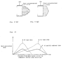
- the main burner 223 comprises the S1 type main swirler 241 wherein fitting angle of the swirler vane 241a is made smaller, thereby premixing of the fuel is in a comparatively irregular state and the premixture there is so formed that the fuel concentration becomes high in a central portion of outlet of the main burner 223 and low in outer peripheral portions of same, as shown by fuel concentration distribution of Fig. 9(a).
- the main burner 224 comprises the S2 type main swirler 242 wherein fitting angle of the swirler vane 242a is made larger, thereby premixing of the fuel is in a comparatively good and regular state, as shown by fuel concentration distribution of Fig. 9(b).
- Fig. 10 is a conceptual view showing distribution of heat generation rate in the combustors corresponding to the types of the main burners comprising the main swirlers mentioned above, wherein the vertical axis shows heat generation rate and the horizontal axis shows distance from the main burner outlet in the combustor central axis direction.
- broken line a shows heat generation rate of a combustor in which only the main burners 223, each having therein the S1 type main swirler 241, are provided
- broken line b shows heat generation rate of a combustor in which only the main burners 224, each having therein the S2 type main swirler 242, are provided, wherein both of these combustors correspond to the mentioned combustor 201 in the prior art and there occurs the concentrated heat generation in the area of a constant distance in the combustor central axis direction resulting in the problem of vibratory combustion.
- the main burner 223 comprising the S1 type main swirler 241 and the main burner 224 comprising the S2 type main swirler 241 are provided alternately on a circumference surrounding the pilot burner 207 in the combustor 212, and the premixture is prevented from becoming a regular state all around in the combustor 212.
- a vibratory combustion caused by the concentrated heat generation is avoided and a stable combustion is attained, so that a low NOx combustor in which a low NOx combustion is not hampered can be obtained.
- main swirler has been described with respect to two types of the S1 type main swirler 241 and the S2 type main swirler 242 in the present embodiment, it is not necessarily limited to these two types. Also, the fitting angle, number, arrangement and direction of the swirler vane of the respective main swirlers are not limited to those shown in Fig. 7 or 8 but may be decided arbitrarily.
- the main swirler may be made in plural types wherein the swirler vane has different fitting angles of the vane to the main swirler central axis direction.
- the number of the main burners is not limited to eight in total as illustrated but two or more types of the main burners may be arranged on a circumference surrounding the pilot burner 207 in the combustor 212 so that a same type may not be adjoined each other and what is important is to avoid the concentrated heat generation.
- a combustor may be constructed such that a plurality of various types of the main burner are arranged on a circumference surrounding a pilot burner so that a same type may not be adjoined each other, wherein the main burner is made by combination of such of the plural types of the main fuel nozzle as described in the third embodiment and such of the plural types of the main swirler as described in the fourth embodiment.
- the heat generation rate distribution in the combustor central axis direction is further dispersed to be averaged, so that a vibratory combustion due to the concentrated heat generation is prevented and a stable combustion is attained and a low NOx combustor in which a low NOx combustion is not hampered can be obtained.
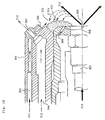
- a combustor of a sixth embodiment according to the presen invention will be described with reference to Figs. 11 and 12. It is to be noted that portions of Figs. 11 and 12 which are same as those of the combustor in the prior art shown in Fig. 15 are given same reference numerals and description thereon will be omitted.
- a pilot nozzle end portion there is provided to a pilot nozzle end portion an annular type cover ring 313, which covers all around an entire circumferential portion of outlet portion of an air injection port 306.
- Central portion of the cover ring 313 is open so that injection of the oil fuel 310 and of the air 311 in the central portion may not be obstructed.
- Peripheral portion of the cover ring 313 extends toward a direction to cross a nozzle central axis orthogonally and its length L is approximately such as so extends as not to cover the water injection port 308.
- the oil fuel 310 is injected from the oil fuel injection port 305, like in the prior art case, and the air 311 for diffusion passes through the air passage 302 in a peripheral portion of the nozzle to be injected from the air injection port 306 of the nozzle end portion.
- the cover ring 313 covers the outer side of outlet portion of the air injection port 306, the air 311 so injected does not flow straight but turns toward the direction to cross the nozzle central axis orthogonally, as shown by flow 311a, to joint the oil fuel 310 to be used for combustion.
- the air 311 flows in the direction to cross the nozzle central axis orthogonally as mentioned above, thereby the mist 321 of the oil fuel scattering into the stagnation area 320 as has been so far formed in the prior art case is prevented from so scattering by the flow 311a of the air, so that the mist 321 does not stick to the nozzle end portion but is blown into the combustion area, thereby there occurs no case of the mist 321 accumulating on the nozzle end portion as an unburnt carbon.
- Fig. 12 is a view seen from line A-A of Fig. 11 to show an entire portion of the cover ring 313.
- the cover ring 313 is made such that a front portion thereof has in its central portion an opening portion 330 of circle shape thereby not to obstruct the fuel injection from the oil fuel injection port 305 and a ring peripheral portion thereof covers all portion around the nozzle end portion.
- the stagnation area so far formed in the prior art case is covered and the mist is prevented from scattering into this area by the air injected thereinto.
- the cover ring 313 so as to cover the air injection port 306 all around the nozzle end portion, thereby the mist of the oil fuel scattering to the nozzle end portion is blown off by the air so as to be prevented from sticking to the nozzle end portion, there occurs no case where the water injection port 308 is plugged and reliability of the nozzle is enhanced.
Landscapes
- Engineering & Computer Science (AREA)
- Chemical & Material Sciences (AREA)
- Combustion & Propulsion (AREA)
- Mechanical Engineering (AREA)
- General Engineering & Computer Science (AREA)
Abstract
Description
- The present invention relates generally to a combustor and more specifically to a combustor which is appropriate for use as a gas turbine combustor.
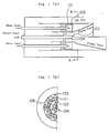
- One example of a premixed flame type combustor which is used as a prior art gas turbine low NOx type combustor is shown in Fig. 13, wherein Fig. 13(a) is a longitudinal cross sectional view of the combustor and Fig. 13(b) is a cross sectional view taken on line C-C of Fig. 13(a).
- In Fig. 13, within a
combustor 201 which is provided to a gas turbine cylinder, there are provided a plurality, eight pieces in this case, ofmain burners 202 around a central axis of thecombustor 201. Each of themain burners 202 comprises therein amain fuel nozzle 203 of same shape for all themain burners 202 and amain swirler 204 of likewise same shape. Also, provided in a portion surrounded by the plurality ofmain burners 202 and along the central axis of thecombustor 201 is apilot burner 207, which comprises therein apilot fuel nozzle 206 and apilot swirler 205 provided around thepilot fuel nozzle 206. - Combustion air flowing inside of an outer periphery of the
combustor 201 turns in the angle of 180° at anair inflow portion 208 to flow in thecombustor 201 passing through themain swirler 204 each of themain burners 202 and thepilot swirler 205 of thepilot burner 207. - In the
pilot burner 205, pilot fuel supplied from thepilot fuel nozzle 206 is burned by the combustion air which has passed through thepilot swirler 205. In themain burner 202, main fuel supplied from themain fuel nozzle 203 and the combustion air which has passed through themain swirler 204 are mixed to form a premixture, which is fired by pilot flame of the pilot fuel so that a low NOx combustion is effected in thecombustor 201. - The premixture formed in the
main burner 202 is fired by the pilot flame of the pilot fuel, as mentioned above, and in this case, as there is substantially a regularity in a mixing state of the premixture between each of the plurality ofmain burners 202, combustion state in each of themain burners 202 becomes regular, which results also in a regularity in heat generation distribution all around in thecombustor 201 along the central axis direction thereof and there occurs a constant area where there is concentrated a large heat generation in thecombustor 201. - For this reason, vibratory combustion is prone to occur due to such concentrated heat generation to cause a non-stability of the combustion, which results in a problem that a low NOx combustion is hampered.
- Fig. 14 is a cross sectional view showing one example of a prior art pilot nozzle of gas turbine. In Fig. 14,
numeral 301 designates a nozzle body andnumeral 302 designates an air passage in a peripheral portion of thenozzle body 301, into whichair 311 is taken. Numeral 303 designates an oil fuel supply pipe, which is provided in a central portion of thenozzle body 301 for leading therethrough anoil fuel 310. Numeral 304 designates a gas fuel passage for leading therethrough agas fuel 312 when such is used. Numeral 305 designates an oil fuel injection port,numeral 306 designates an air injection port andnumeral 307 designates a gas fuel injection port. In the nozzle so constructed, both of theoil fuel 310 and thegas fuel 312 are usable wherein the fuel is injected from a tip end of the nozzle and theair 311 for diffusion andwater 309 for cooling are injected as described later so that combustion is effected. - Fig. 15 is an enlarged cross sectional view of a tip end portion of the pilot nozzle of Fig. 14. In Fig. 15, when an oil fuel is used, the
oil fuel 310 is supplied through the oilfuel supply pipe 303 to be injected for combustion into a combustion chamber from the oilfuel injection port 305 of the central portion. On the other hand, theair 311 flows through theair passage 302 in the peripheral portion of thenozzle body 301 to be injected from theair injection port 306 for diffusion of the fuel. Also, thewater 309 is injected from awater injection port 308 provided around the oilfuel injection port 305 to cool a peripheral portion of the oilfuel injection port 305. - In the above-mentioned pilot nozzle, the
oil fuel 310 injected from the oilfuel injection port 305 spreads into the surrounding area, as shown in Fig. 15. On the other hand, theair 311 is injected from theair injection port 306 in such an angle as to cross theoil fuel 310 so spreading, thus there is formed therebetween astagnation area 320 into which neither theair 311 nor theoil fuel 310 comes. But there is formed amist 321 by a portion of theoil fuel 310 scattering there and this mist flows into thisstagnation area 320 and sticks to the tip end of the nozzle to accumulate there as anunburnt carbon 322. Thisunburnt carbon 322 increases gradually so that thewater injection port 308 may be plugged and the flow of theair 311 from theair injection port 306 may be obstructed, thereby there arises a problem that the cooling performance of the peripheral portion of the oilfuel injection port 305 is deteriorated or the combustion performance is badly affected. - In case the oil fuel is used in the prior art gas turbine pilot nozzle, as mentioned above, there is formed the
stagnation area 320 between the oilfuel injection port 305 and theair injection port 306 and themist 321 of theoil fuel 310 scatters and sticks to the tip end of the nozzle to accumulate while being carbonised as theunburnt carbon 322, which results in plugging thewater injection port 308 to obstruct the injection of the water to thereby cause a problem to affect the nozzle performance such that the cooling performance of the peripheral portion of the oilfuel injection port 305 is deteriorated or the flow of the injected air is obstructed. - It is therefore an object of the present invention to provide a combustor which is able to dissolve shortcomings in the prior art combustor as shown in Fig. 13 that there occurs easily a vibratory combustion due to a concentrated heat generation resulting in an unstable combustion.
- It is also an object of the present invention to provide a low NOx combustor in which there is formed a heat generation distribution that is more averaged in an axial direction of the combustor so that a heat generation may be less concentrated on a constant area, a stable combustion may be attained with less vibratory combustion and a low NOx combustion may not be hampered.
- It is further an object of the present invention to provide a combustor which is able to dissolve shortcomings in the prior art combustor as shown in Figs. 14, 15 that there is formed an unburnt carbon sticking to and accumulating on a stagnation area.
- In order to attain said object not to cause a vibratory combustion, the present invention provides a combustor comprising; a pilot fuel nozzle unit having therein a plurality of pilot fuel nozzles; and a plurality of main premixing nozzle units disposed on a coaxial circumference surrounding said pilot fuel nozzle unit for mixing fuel supplied from a main fuel nozzle of the respective main premixing nozzle units with air to form a premixture, characterized in that said plurality of pilot fuel nozzles are arranged irregularly in a circumferential direction of said pilot fuel nozzle unit.
- In the combustor so constructed that the pilot fuel nozzles are arranged irregularly in a circumferential direction of the pilot fuel nozzle unit, the pilot fuel nozzles do not necessarily correspond to the main premixing nozzles one to one.
- While the premixture coming from the main premixing nozzle which is positioned to correspond to the pilot fuel nozzle generates combustion with short flames, the premixture coming from the main premixing nozzle which is in a position where there is no corresponding pilot fuel nozzle generates combustion with long flames. Thus, in the combustor of the present invention so constructed, there are generated combustions of different flame lengths, thereby the heat generation rate distribution is dispersed and there occurs no vibratory combustion.
- Also, in order to attain the same object, the present invention provides a combustor constructed such that the premixture supplied from some of the plurality of main premixing nozzle units is made leaner than that supplied from the remaining main premixing nozzle units.
- In the combustor of the present invention so constructed, combustion speed in the main premixing nozzle in which the premixture is made leaner is slow to form long flames and combustion speed in the main premixing nozzle in which the premixture is not made so leaner is fast to form comparatively short flames.
- Thus, in the combustor of the present invention in which the premixture supplied from some of the plurality of main premixing nozzles is made leaner than that supplied from the remainder, the heat generation rate can be dispersed, thereby a vibratory combustion can be avoided.
- Also, in order to attain said object to obtain a low NOx combustor, the present invention provides a combustor comprising; a pilot burner provided on a central axis of the combustor; and a plurality of main burners provided around said pilot burner, each having therein a main fuel nozzle disposed on a central axis each of said main burners and a main swirler disposed around said main fuel nozzle, characterized in that two or more types of said main burners having different numbers of fuel injection ports of said main fuel nozzle are provided in a circumferential direction of the combustor so that a same one of said types may not be adjoined each other.
- According to the combustor of the present invention, two or more types of the main burners having different numbers of fuel injection ports of the main fuel nozzle are provided in the combustor on a circumference surrounding the pilot burner so that a same type of said types may not be adjoined each other, thereby the premixture does not become a constant state all around in the combustor, the portion where the heat generation rate is high is dispersed in the central axis direction of the combustor, a vibratory combustion caused by the concentrated heat generation is avoided and a stable combustion is attained, hence a low NOx combustor in which a low NOx combustion is not hampered can be obtained.
- Also, in order to attain the same object, the present invention provides a combustor comprising; a pilot burner provided on a central axis of the combustor; and a plurality of main burners provided around said pilot burner, each having therein a main fuel nozzle disposed on a central axis each of said main burners and a main swirler disposed around said main fuel nozzle, characterized in that two or more types of said main burners having different fitting angles of swirler vanes relative to a central axis direction of said main swirler are provided in a circumferential direction of the combustor so that a same one of said types may not be adjoined each other.
- According to the combustor of the present invention, two or more types of the main burners having different fitting angles of swirler vanes relative to the main swirler central axis direction are provided in the combustor on a circumference surrounding the pilot burner so that a same type of said types may not be adjoined each other, thereby the premixture does not become a constant state all around in the combustor and the portion where the heat generation rate is high is dispersed to be averaged in the central axis direction of the combustor. Hence, a vibratory combustion caused by the concentrated heat generation is avoided, a stable combustion is attained and a low NOx combustor in which a low NOx combustion is not hampered can be obtained.
- Also, in order to attain the same object, the present invention provides a combustor comprising; a pilot burner provided on a central axis of the combustor; and a plurality of main burners provided around said pilot burner, each having therein a main fuel nozzle disposed on a central axis each of said main burners and a main swirler disposed around said main fuel nozzle, characterized in that a plurality of types of said main burners in which two or more types of said main burners having different numbers of fuel injection ports of said main fuel nozzle and two or more types of said main burners having different fitting angles of swirler vanes relative to a central axis direction of said main swirler are combined are provided in a circumferential direction of the combustor so that a same one of said types may not be adjoined each other.
- According to the combustor of the present invention, the heat generation rate distribution is further dispersed to be averaged, thereby a vibratory combustion due to the concentrated heat generation is avoided and a stable combustion is attained, hence a low NOx combustor in which a low NOx combustion is not hampered can be obtained.
- Next, in order to attain the object mentioned above to provide a combustor which is able to dissolve the shortcomings in the prior art that an unburnt carbon sticks to and accumulate on the nozzle tip end, the present invention provides a combustor comprising a fuel injection nozzle, said fuel injection nozzle having therein an oil fuel supply pipe provided in a nozzle central portion; an oil fuel injection port provided at a nozzle tip end for injecting oil fuel supplied from said oil fuel supply pipe; an air passage provided around said oil fuel supply pipe; and an air injection port provided around said oil fuel injection port of the nozzle tip end for injecting air supplied from said air passage, characterized in that there is provided to said nozzle tip end a cover ring which covers an outlet portion of said air injection port from outside of said nozzle tip end and has an opening at a central portion of itself.
- According to the combustor of the present invention, there is provided the cover ring to the nozzle tip end and said cover ring covers the air outlet portion of the air injection port of the periphery of the nozzle tip end in a ring shape from outside of the nozzle tip end and has the opening in its central portion so that oil fuel injection from the oil fuel injection port can be done sufficiently. Thereby, by the effect of the cover ring, the air injected flows toward the nozzle central axis direction, and even if the mist of the oil fuel scatters and wants to stick, it is blown to be prevented from sticking. In the prior art case, there has been formed a stagnation area between the air injection port and the oil fuel injection port where the mist of the oil fuel scatters and sticks to the nozzle tip end and this sticking mist is carbonized to accumulate as an unburnt carbon, which resulted in shortcomings that the water injection port around the oil fuel injection port is plugged, etc. In the combustor of the present invention, however, the mist is prevented from sticking, hence there is caused no accumulation of the unburnt carbon.
-
- Fig. 1 is a view showing a combustor of a first embodiment according to the present invention, wherein Fig. 1(a) is a longitudinal cross sectional view and Fig. 1(b) is a half cross sectional view taken on line A-A of Fig. 1(a).
- Fig. 2 is a view showing a combustor of a second embodiment according to the present invention, wherein Fig. 2(a) is a longitudinal cross sectional view and Fig. 2(b) is a half cross sectional view taken on line A-A of Fig. 2(a).
- Fig. 3 is a view showing a low NOx combustor of a third embodiment according to the present invention, wherein Fig. 3(a) is a longitudinal cross sectional view and Fig. 3(b) is a half cross sectional view taken on line A-A of Fig. 3(a).
- Fig. 4 is an enlarged view of a nozzle of X-portion of Fig. 3(a), wherein Fig. 4(a) is a longitudinal, partly cut away, view of an N1 type nozzle, Fig. 4(a1) is a cross sectional view taken on line D-D of Fig. 4(a), Fig. 4(a2) is a cross sectional view taken on line E-E of Fig. 4(a), Fig. 4(b) is a longitudinal, partly cut away, cross sectional view of an N2 type nozzle and Fig. 4(b1) is a cross sectional view taken on line F-F of Fig. 4(b).
- Fig. 5 is an explanatory view of fuel concentration distribution in the combustor of the third embodiment, wherein Fig. 5(a) shows that at a
main burner 221 outlet and Fig. 5(b) shows that at amain burner 222 outlet. - Fig. 6 is a conceptual view of heat generation rate in the combustor of the third embodiment.
- Fig. 7 is a view showing a low NOx combustor of a fourth embodiment according to the present invention, wherein Fig. 7(a) is a longitudinal cross sectional view and Fig. 7(b) is a half cross sectional view taken on line B-B of Fig. 7(a).
- Fig. 8 is an enlarged view of a main swirler of Y-portion of Fig. 7(a), wherein Fig. 8(a) is a view showing those of an S1 type main swirler, Fig. 8(a1) is a view seen from line G-G of Fig. 8(a), Fig. 8(b) is a view showing those of an S2 type main swirler and Fig. 8(b1) is a view seen from line H-H of Fig. 8(b).
- Fig. 9 is an explanatory view of fuel concentration distribution in the combustor of the fourth embodiment, wherein Fig. 9(a) shows that at a
main burner 223 outlet and Fig. 9(b) shows that at amain burner 224 outlet. - Fig. 10 is a conceptual view of heat generation rate in the combustor of the fourth embodiment.
- Fig. 11 is a cross sectional view of a nozzle tip end portion of a combustor of a sixth embodiment according to the present invention.
- Fig. 12 is a view seen from line A-A of Fig. 11.
- Fig. 13 is a view showing an example of a low NOx combustor in the prior art, wherein Fig. 13(a) is a longitudinal cross sectional view and Fig. 13(b) is a half cross sectional view taken on line C-C of Fig. 13(a).
- Fig. 14 is a cross sectional view of a pilot nozzle in the prior art.
- Fig. 15 is an enlarged cross sectional view of a tip end portion of the pilot nozzle of Fig. 14.
- A combustor of a first embodiment according to the present invention will be described with reference to Fig. 1. In Fig. 1, numeral 104 designates a pilot fuel nozzle unit. Around the pilot
fuel nozzle unit 104 and on a coaxial circumference thereof, there are provided a plurality of mainpremixing nozzle units 102, each comprising therein amain fuel nozzle 101 disposed in a central portion thereof. Fuel supplied from themain fuel nozzle 101 is mixed with air to form a premixture. - On the other hand, in the pilot
fuel nozzle unit 104, there are provided a plurality ofpilot fuel nozzles 103, which are arranged irregularly in a circumferential direction so that the construction is made such that there is formed aportion 105 where, none of thepilot fuel nozzles 103 being provided, some of the main premixing nozzle units disposed around the pilotfuel nozzle unit 104 may not be correspondingly provided to thepilot fuel nozzles 103. - This is a characteristic feature in the construction as compared with the prior art combustor where each of the main premixing nozzle units is arranged corresponding to each of the pilot fuel nozzles.
- In the combustor of Fig. 1 constructed as above, the fuel supplied from the
main fuel nozzle 101 is mixed with air in the respective mainpremixing nozzle units 102 to form the premixture. In this combustor, there is formed theportion 105 where none of thepilot fuel nozzles 103 is provided in the pilotfuel nozzle unit 104, hence in thisportion 105, the premixture which has been injected from the respective mainpremixing nozzle units 102 burns with long flames. It is to be noted that the arrangement and number of theportion 105 where none of thepilot fuel nozzles 103 is provided may be decided arbitrarily. - On the contrary, the premixture which has been injected from the respective main
premixing nozzle units 102 in the portion where thepilot fuel nozzles 103 are provided burns with comparatively short flames. Combustion state of such long flames and short flames is shown schematically in Fig. 1(a). Thus, such a combustion as having differences in the flame length takes place, thereby the heat generation rate distribution is dispersed and occurrence of vibratory combustion is prevented. - A combustor of a second embodiment according to the present invention will be described with reference to Fig. 2. In the combustor shown in Fig. 2, each of the
pilot fuel nozzles 103 is provided corresponding to each of the mainpremixing nozzle units 102 and there is formed none of theportion 105 where none of thepilot fuel nozzles 103 is provided as in the combustor of the first embodiment. - In the combustor of the second embodiment, flow rate of the fuel supplied from a
main fuel nozzle 106 is reduced to 60 to 90% of the flow rate of the fuel supplied from the othermain fuel nozzle 101. - Thus, the premixture which is injected from the respective main
premixing nozzle units 107 which comprise themain fuel nozzle 106 supplying the less flow rate of the main fuel has a lean fuel concentration, as compared with the premixture injected from the respective mainpremixing nozzle units 102 which comprise themain fuel nozzle 101 supplying no such less flow rate of the main fuel. - It is to be noted that which of the plurality, eight pieces for example, of the main premixing nozzle units is to be changed to the lean fuel and in what degree of the fuel leanness, etc. may be decided arbitrarily.
- Construction of other portions of the combustor of the second embodiment is same as that of the combustor of the first embodiment with repeated description being omitted.
- In the combustor of Fig. 2 constructed as above, the fuels supplied from the
main fuel nozzles premixing nozzle units pilot fuel nozzles 103. - In the above, the less fuel flow rate supplied from the
main fuel nozzle 106 is 60 to 90%, for example, of that supplied from themain fuel nozzle 101 and the premixture supplied from the respective main premixing nozzle units (lean) 107 provided with themain fuel nozzle 106 is made leaner than that supplied from the respective mainpremixing nozzle units 102 provided with themain fuel nozzle 101. - As shown in Fig. 2(a), the premixture supplied from the respective main
premixing nozzle units 102 having no such leaner fuel concentration burns with comparatively short flames, while the leaner premixture supplied from the respective mainpremixing nozzle units 107 having the leaner fuel concentration burns with long flames as the combustion speed is low. - Thus, according to the combustor of the second embodiment, the premixture supplied from some of the main premixing nozzle units is made leaner than that supplied from the remainder, thereby the heat generation rate can be dispersed and occurrence of vibratory combustion can be avoided.
- Next, a combustor of a third embodiment according to the present invention will be described with reference to Figs. 3 to 6. In Fig. 3, a
main swirler 204, apilot swirler 205, apilot fuel nozzle 206, apilot burner 207 and anair inflow portion 208 are same as those of the prior art described in Fig. 13. But in acombustor 201 of the present embodiment, in place of themain fuel nozzle 203 having a same common shape as shown in Fig. 13, there are provided two types ofmain burners main fuel nozzles - That is, the
main burner 221 of one type thereof comprises an N1 typemain fuel nozzle 231 as shown in Fig. 4(a) and themain burner 222 of the other type comprises an N2 typemain fuel nozzle 232 as shown in Fig. 4(b), and these two types of themain burners pilot burner 207 in thecombustor 211 as shown in Fig. 3(b). Themain swirler 204 is of a same shape both for themain burners - As shown in Fig. 4(a), the N1 type
main fuel nozzle 231 has two sectional planes of positions wherefuel injection ports 231a are provided, one of said planes taken on line D-D of Fig. 4(a) being shown in Fig. 4(a1) and the other taken on line E-E of Fig. 4(a) being shown in Fig. 4(a2). As seen there, there are provided fourfuel injection ports 231a in each of said planes and directions of thefuel injection ports 231a alternate mutually between the two planes. - On the other hand, as shown in Fig. 4(b), the N2 type
main fuel nozzle 232 has one sectional plane of position wherefuel injection ports 232a are provided, said plane taken on line F-F of Fig. 4(b) being shown in Fig. 4(b1). As seen there, there are provided fourfuel injection ports 232a in said plane. - Accordingly, the number of the
fuel injection ports 231a of the N1 typemain fuel nozzle 231 is double of that of thefuel injection ports 232a of the N2 typemain fuel nozzle 232, but a total injection port area of thefuel injection ports 231a of the N1 typemain fuel nozzle 231 is made equal to that of thefuel injection ports 232a of the N2 typemain fuel nozzle 232, thereby the construction is made such that the fuel flow rate from each type of the main fuel nozzles becomes equal. - In the mentioned third embodiment, the
main burner 221 comprises the N1 type main fuel nozzle which has many of thefuel injection ports 231a, thereby fuel injection rate perfuel injection port 231a is small, so that penetrating force of the fuel is lowered. Hence, the premixture there is so formed that the fuel concentration becomes high in a central portion of outlet of themain burner 221 and low in outer peripheral portions of same, as shown by fuel concentration distribution of Fig. 5(a). - On the other hand, the
main burner 222 comprises the N2 typemain fuel nozzle 232 which has less number of thefuel injection ports 232a, thereby fuel injection rate perfuel injection port 232a is large, so that penetrating force of the fuel becomes high as compared with thefuel injection port 231a. Hence, the premixture there is so formed that the fuel concentration becomes high in outer peripheral portions of outlet of themain burner 222 reversely, as shown by the fuel concentration distribution of Fig. 5(b). - The premixture which has come out of the main burner is fired by peripheral pilot flames as heat source. If the fuel concentration is low in the outer peripheral portions of the burner outlet, like in the
main burner 221, the combustion speed is slow and flames become longer and then if the flames spread to the central portion of the premixture, as the fuel concentration there is high, a strong heat generation occurs suddenly in the area comparatively apart from the outlet of themain burner 221. On the other hand, if the fuel concentration is high in the outer peripheral portions of the burner outlet, like in themain burner 222, the combustion speed becomes higher and flames become shorter, and a strong heat generation occurs in the area comparatively near the outlet of themain burner 222. - In any case, if the main burners comprising the main fuel nozzles of same type would be arranged on an entire circumference of the
combustor 211, like in the prior art case, it is so considered that there would be concentrated a high heat generation in a constant area of the combustor and there would occur the mentioned vibratory combustion due to this concentrated heat generation. - Fig. 6 is a conceptual view showing distribution of heat generation rate in the combustors corresponding to the types of the main burners mentioned above, wherein the vertical axis shows heat generation rate and the horizontal axis shows distance from the main burner outlet in the combustor central axis direction.
- In Fig. 6, broken line a shows the heat generation rate of a combustor in which only the
main burners 221, each having therein the N1 typemain fuel nozzle 231, are provided, and broken line b shows the heat generation rate of a combustor in which only themain burners 222, each having therein the N2 typemain fuel nozzle 232, are provided, wherein both of these combustors correspond to the mentionedcombustor 201 in the prior art and there occurs the concentrated heat generation in the area of a constant distance in the combustor central axis direction resulting in the problem of vibratory combustion. - In the present third embodiment, as mentioned above, the
main burner 221 comprising the N1 typemain fuel nozzle 231 and themain burner 222 comprising the N2 typemain fuel nozzle 232 are provided alternately on a circumference surrounding thepilot burner 207 in thecombustor 211, and the premixture is prevented from becoming a regular state all around in thecombustor 211. Thereby, as shown by solid line c in Fig. 6, there are formed mixedly an area where the combustion speed is fast in the combustor central axis direction and an area where it is slow in the same direction and the portion where the heat generation rate is high is dispersed. Thus, a vibratory combustion caused by the concentrated heat generation is avoided and a stable combustion is attained, so that a low NOx combustor in which a low NOx combustion is not hampered can be obtained. - It is to be noted that although the main fuel nozzle has been described with respect to two types of the N1 type
main fuel nozzle 231 and the N2 typemain fuel nozzle 232 in the present third embodiment, it is not necessarily limited to these two types. Also, the number, arrangement and direction of the fuel injection ports of the respective main fuel nozzles are not limited to those shown in Fig. 1 or 2 but may be decided arbitrarily. - That is, the main burner may be made in plural types wherein the main fuel nozzle has different numbers of the fuel injection ports. Also, the number of the main burners is not limited to eight in total as illustrated but two or more types of the main burners may be arranged on a circumference surrounding the
pilot burner 207 in thecombustor 211 so that a same type may not be adjoined each other and what is important is to avoid the concentrated heat generation. - A combustor of a fourth embodiment will be described with reference to Fig. 7. In Fig. 7, a
main fuel nozzle 203, apilot swirler 205, apilot fuel nozzle 206, apilot burner 207 and anair inflow portion 208 are same as those of the prior art described in Fig. 13. But in acombustor 212 of the present embodiment, in place of themain swirler 204 having a same common shape as shown in Fig. 13, there are provided two types ofmain burners main swirlers - In the above, an S1 type
main swirler 241 has itsswirler vane 241a fitted inclinedly with an angle of 25° to an axial direction of the S1 typemain swirler 241 as shown in Fig. 8(a) and an S2 typemain swirler 242 has itsswirler vane 242a fitted inclinedly with an angle of 35° to an axial direction of the S2 typemain swirler 242 as shown in Fig. 8(b). - That is, the
main burner 223 of one type comprises the S1 typemain swirler 241 shown in Fig. 8(a) and themain burner 224 of the other type comprises the S2 typemain swirler 242 shown in Fig. 8(b), and these two types of themain burners pilot burner 207 in thecombustor 212 as shown in Fig. 7(b). Themain fuel nozzle 203 is of a same shape both for themain burners - In the present fourth embodiment, the
main burner 223 comprises the S1 typemain swirler 241 wherein fitting angle of theswirler vane 241a is made smaller, thereby premixing of the fuel is in a comparatively irregular state and the premixture there is so formed that the fuel concentration becomes high in a central portion of outlet of themain burner 223 and low in outer peripheral portions of same, as shown by fuel concentration distribution of Fig. 9(a). - On the other hand, the
main burner 224 comprises the S2 typemain swirler 242 wherein fitting angle of theswirler vane 242a is made larger, thereby premixing of the fuel is in a comparatively good and regular state, as shown by fuel concentration distribution of Fig. 9(b). - Fig. 10 is a conceptual view showing distribution of heat generation rate in the combustors corresponding to the types of the main burners comprising the main swirlers mentioned above, wherein the vertical axis shows heat generation rate and the horizontal axis shows distance from the main burner outlet in the combustor central axis direction.
- In Fig. 10, broken line a shows heat generation rate of a combustor in which only the
main burners 223, each having therein the S1 typemain swirler 241, are provided, and broken line b shows heat generation rate of a combustor in which only themain burners 224, each having therein the S2 typemain swirler 242, are provided, wherein both of these combustors correspond to the mentionedcombustor 201 in the prior art and there occurs the concentrated heat generation in the area of a constant distance in the combustor central axis direction resulting in the problem of vibratory combustion. - In the present fourth embodiment, as mentioned above, the
main burner 223 comprising the S1 typemain swirler 241 and themain burner 224 comprising the S2 typemain swirler 241 are provided alternately on a circumference surrounding thepilot burner 207 in thecombustor 212, and the premixture is prevented from becoming a regular state all around in thecombustor 212. Thereby, as shown by solid line c in Fig. 10, there are formed mixedly an area where the combustion speed is fast in the combustor central axis direction and an area where it is slow in the same direction and the portion where the heat generation rate is high is dispersed. Thus, a vibratory combustion caused by the concentrated heat generation is avoided and a stable combustion is attained, so that a low NOx combustor in which a low NOx combustion is not hampered can be obtained. - It is to be noted that although the main swirler has been described with respect to two types of the S1 type
main swirler 241 and the S2 typemain swirler 242 in the present embodiment, it is not necessarily limited to these two types. Also, the fitting angle, number, arrangement and direction of the swirler vane of the respective main swirlers are not limited to those shown in Fig. 7 or 8 but may be decided arbitrarily. - That is, the main swirler may be made in plural types wherein the swirler vane has different fitting angles of the vane to the main swirler central axis direction. Also, the number of the main burners is not limited to eight in total as illustrated but two or more types of the main burners may be arranged on a circumference surrounding the
pilot burner 207 in thecombustor 212 so that a same type may not be adjoined each other and what is important is to avoid the concentrated heat generation. - As a fifth embodiment, a combustor may be constructed such that a plurality of various types of the main burner are arranged on a circumference surrounding a pilot burner so that a same type may not be adjoined each other, wherein the main burner is made by combination of such of the plural types of the main fuel nozzle as described in the third embodiment and such of the plural types of the main swirler as described in the fourth embodiment.
- According to the fifth embodiment, in addition to the effect of the third and fourth embodiments, the heat generation rate distribution in the combustor central axis direction is further dispersed to be averaged, so that a vibratory combustion due to the concentrated heat generation is prevented and a stable combustion is attained and a low NOx combustor in which a low NOx combustion is not hampered can be obtained.
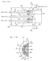
- Next, a combustor of a sixth embodiment according to the presen invention will be described with reference to Figs. 11 and 12. It is to be noted that portions of Figs. 11 and 12 which are same as those of the combustor in the prior art shown in Fig. 15 are given same reference numerals and description thereon will be omitted.
- In Fig. 11, there is provided to a pilot nozzle end portion an annular
type cover ring 313, which covers all around an entire circumferential portion of outlet portion of anair injection port 306. Central portion of thecover ring 313 is open so that injection of theoil fuel 310 and of theair 311 in the central portion may not be obstructed. Peripheral portion of thecover ring 313 extends toward a direction to cross a nozzle central axis orthogonally and its length L is approximately such as so extends as not to cover thewater injection port 308. - In the construction mentioned above, the
oil fuel 310 is injected from the oilfuel injection port 305, like in the prior art case, and theair 311 for diffusion passes through theair passage 302 in a peripheral portion of the nozzle to be injected from theair injection port 306 of the nozzle end portion. But, as thecover ring 313 covers the outer side of outlet portion of theair injection port 306, theair 311 so injected does not flow straight but turns toward the direction to cross the nozzle central axis orthogonally, as shown by flow 311a, to joint theoil fuel 310 to be used for combustion. - The
air 311 flows in the direction to cross the nozzle central axis orthogonally as mentioned above, thereby themist 321 of the oil fuel scattering into thestagnation area 320 as has been so far formed in the prior art case is prevented from so scattering by the flow 311a of the air, so that themist 321 does not stick to the nozzle end portion but is blown into the combustion area, thereby there occurs no case of themist 321 accumulating on the nozzle end portion as an unburnt carbon. - Fig. 12 is a view seen from line A-A of Fig. 11 to show an entire portion of the
cover ring 313. As shown there, thecover ring 313 is made such that a front portion thereof has in its central portion anopening portion 330 of circle shape thereby not to obstruct the fuel injection from the oilfuel injection port 305 and a ring peripheral portion thereof covers all portion around the nozzle end portion. By thiscover ring 313, the stagnation area so far formed in the prior art case is covered and the mist is prevented from scattering into this area by the air injected thereinto. - According to the present sixth embodiment, as described above, there is provided to the end portion of the
nozzle body 301 thecover ring 313 so as to cover theair injection port 306 all around the nozzle end portion, thereby the mist of the oil fuel scattering to the nozzle end portion is blown off by the air so as to be prevented from sticking to the nozzle end portion, there occurs no case where thewater injection port 308 is plugged and reliability of the nozzle is enhanced.
Claims (6)
- A combustor comprising; a pilot fuel nozzle unit 104 having therein a plurality of pilot fuel nozzles 103; and a plurality of main premixing nozzle units 102 disposed on a coaxial circumference surrounding said pilot fuel nozzle unit 104 for mixing fuel supplied from a main fuel nozzle 101 of the respective main premixing nozzle units 102 with air to form a premixture, characterized in that said plurality of pilot fuel nozzles 103 are arranged irregularly in a circumferential direction of said pilot fuel nozzle unit 104.
- A combustor comprising; a pilot fuel nozzle unit 104 having therein a plurality of pilot fuel nozzles 103; and a plurality of main premixing nozzle units 102 disposed on a coaxial circumference surrounding said pilot fuel nozzle unit 104 for mixing fuel supplied from a main fuel nozzle 101 of the respective main premixing nozzle units 102 with air to form a premixture, characterized in that the premixture supplied from some 107 of said plurality of main premixing nozzle units 102 is made leaner than that supplied from a remainder thereof.
- A combustor comprising; a pilot burner 207 provided on a central axis of the combustor 211; and a plurality of main burners 221, 222 provided around said pilot burner 207, each having therein a main fuel nozzle 231, 232 disposed on a central axis each of said main burners 221, 222 and a main swirler 204 disposed around said main fuel nozzle 231, 232, characterized in that two or more types of said main burners 221, 222 having different numbers of fuel injection ports 231a, 232a of said main fuel nozzle 231, 232 are provided in a circumferential direction of the combustor 211 so that a same one of said types may not be adjoined each other.
- A combustor comprising; a pilot burner 207 provided on a central axis of the combustor 212; and a plurality of main burners 223, 224 provided around said pilot burner 207, each having therein a main fuel nozzle 203 disposed on a central axis each of said main burners 223, 224 and a main swirler 241, 242 disposed around said main fuel nozzle 203, characterized in that two or more types of said main burners 223, 224 having different fitting angles of swirler vanes 241a, 242a relative to a central axis direction of said main swirler 241, 242 are provided in a circumferential direction of the combustor 212 so that a same one of said types may not be adjoined each other.
- A combustor characterized in that a plurality of types of main burners in which the main burners 221, 222 comprising the main fuel nozzles 231, 232 as mentioned in Claim 3 and the main burners 223, 224 comprising the main swirlers 241, 242 as mentioned in Claim 4 are combined are provided in a circumferential direction of the combustor so that a same one of said types may not be adjoined each other.
- A combustor comprising a fuel injection nozzle 301, said fuel injection nozzle 301 having therein an oil fuel supply pipe 303 provided in a central portion of the nozzle 301; an oil fuel injection port 305 provided at a nozzle tip end for injecting oil fuel 310 supplied from said oil fuel supply pipe 303; an air passage 302 provided around said oil fuel supply pipe 303; and an air injection port 306 provided around said oil fuel injection port 305 of the nozzle tip end for injecting air 311 supplied from said air passage 302, characterized in that there is provided to said nozzle tip end a cover ring 313 which covers an outlet portion of said air injection port 306 from outside of said nozzle tip end and has an opening at a central portion of itself.
Applications Claiming Priority (6)
| Application Number | Priority Date | Filing Date | Title |
|---|---|---|---|
| JP10464598A JPH11294770A (en) | 1998-04-15 | 1998-04-15 | Combuster |
| JP10464598 | 1998-04-15 | ||
| JP10205289A JP2000039148A (en) | 1998-07-21 | 1998-07-21 | Gas turbine combustor nozzle |
| JP20528998 | 1998-07-21 | ||
| JP23064998A JP3443009B2 (en) | 1998-08-17 | 1998-08-17 | Low NOx combustor |
| JP23064998 | 1998-08-17 |
Publications (3)
| Publication Number | Publication Date |
|---|---|
| EP0952392A2 true EP0952392A2 (en) | 1999-10-27 |
| EP0952392A3 EP0952392A3 (en) | 2000-07-19 |
| EP0952392B1 EP0952392B1 (en) | 2003-08-06 |
Family
ID=27310276
Family Applications (1)
| Application Number | Title | Priority Date | Filing Date |
|---|---|---|---|
| EP99106822A Expired - Lifetime EP0952392B1 (en) | 1998-04-15 | 1999-04-06 | Combustor |
Country Status (4)
| Country | Link |
|---|---|
| US (1) | US6267583B1 (en) |
| EP (1) | EP0952392B1 (en) |
| CA (1) | CA2268730C (en) |
| DE (1) | DE69910106T2 (en) |
Cited By (3)
| Publication number | Priority date | Publication date | Assignee | Title |
|---|---|---|---|---|
| GB2355517A (en) * | 1999-08-18 | 2001-04-25 | Abb | Method for generating hot gasses in a combustion device and combustion device for carrying out the method |
| EP1288576A2 (en) * | 2001-08-24 | 2003-03-05 | Mitsubishi Heavy Industries, Ltd. | Gas turbine combustor |
| GB2392491A (en) * | 1999-08-18 | 2004-03-03 | Alstom | A combustion device for generating hot gases |
Families Citing this family (18)
| Publication number | Priority date | Publication date | Assignee | Title |
|---|---|---|---|---|
| US20050003316A1 (en) * | 2003-05-31 | 2005-01-06 | Eugene Showers | Counterflow fuel injection nozzle in a burner-boiler system |
| US20070057090A1 (en) * | 2003-05-31 | 2007-03-15 | Bernard Labelle | Counterflow Fuel Injection Nozzle in a Burner-Boiler System |
| EP1645805A1 (en) * | 2004-10-11 | 2006-04-12 | Siemens Aktiengesellschaft | burner for fluidic fuels and method for operating such a burner |
| JP4476176B2 (en) | 2005-06-06 | 2010-06-09 | 三菱重工業株式会社 | Gas turbine premixed combustion burner |
| DE102007009922A1 (en) * | 2007-02-27 | 2008-08-28 | Ulrich Dreizler | Liquid or gaseous fuel combusting method for combustion chamber, involves arranging individual flames, such that common flame forms hollow flame with appropriate hollow space downstream to baffle plate |
| US9062563B2 (en) * | 2008-04-09 | 2015-06-23 | General Electric Company | Surface treatments for preventing hydrocarbon thermal degradation deposits on articles |
| CN101571293B (en) * | 2008-04-28 | 2011-04-13 | 于治华 | High-efficiency honeycomb cyclone type combustor |
| US8127713B2 (en) * | 2008-12-12 | 2012-03-06 | Sokudo Co., Ltd. | Multi-channel developer system |
| US20110314831A1 (en) * | 2010-06-23 | 2011-12-29 | Abou-Jaoude Khalil F | Secondary water injection for diffusion combustion systems |
| KR101470774B1 (en) * | 2011-03-30 | 2014-12-08 | 미츠비시 쥬고교 가부시키가이샤 | Nozzle, gas turbine combustor and gas turbine |
| WO2013128572A1 (en) | 2012-02-28 | 2013-09-06 | 三菱重工業株式会社 | Combustor and gas turbine |
| GB2504468B (en) * | 2012-07-27 | 2017-03-22 | Edwards Ltd | Burner Nozzle Reciprocating Scraper Arrangement for Reducing Effluent Gas Deposits |
| JP5984770B2 (en) | 2013-09-27 | 2016-09-06 | 三菱日立パワーシステムズ株式会社 | Gas turbine combustor and gas turbine engine equipped with the same |
| CN106194437B (en) * | 2016-08-26 | 2017-12-12 | 天津成立航空技术有限公司 | A kind of Aero-Space engine fuel injection system component and its fuel injection method |
| CN107575869B (en) * | 2017-08-25 | 2024-01-26 | 西安石油大学 | Energy-saving low NOx combustor suitable for biomass biogas |
| KR102091043B1 (en) * | 2018-05-30 | 2020-03-20 | 두산중공업 주식회사 | Nozzle for combustor, combustor, and gas turbine including the same |
| US11156360B2 (en) * | 2019-02-18 | 2021-10-26 | General Electric Company | Fuel nozzle assembly |
| KR102312716B1 (en) * | 2020-06-22 | 2021-10-13 | 두산중공업 주식회사 | Fuel injection device for combustor, nozzle, combustor, and gas turbine including the same |
Family Cites Families (15)
| Publication number | Priority date | Publication date | Assignee | Title |
|---|---|---|---|---|
| US3115851A (en) * | 1960-05-11 | 1963-12-31 | Foster Wheeler Corp | Multi-fuel burner |
| US3834858A (en) * | 1973-03-22 | 1974-09-10 | Babcock & Wilcox Co | Fuel burner |
| US4356698A (en) * | 1980-10-02 | 1982-11-02 | United Technologies Corporation | Staged combustor having aerodynamically separated combustion zones |
| JPS5835308A (en) * | 1981-08-28 | 1983-03-02 | Babcock Hitachi Kk | Combustion method preventing resonance and its apparatus |
| JPS5977206A (en) * | 1982-10-25 | 1984-05-02 | Babcock Hitachi Kk | Burner device |
| KR960005758B1 (en) * | 1991-05-07 | 1996-05-01 | 산요덴끼 가부시끼가이샤 | Gas burner |
| US5373694A (en) * | 1992-11-17 | 1994-12-20 | United Technologies Corporation | Combustor seal and support |
| JPH0785388A (en) * | 1993-09-10 | 1995-03-31 | Orient Burein Kk | System for commanding and controlling public peace maintenance and disaster prevention |
| US5415114A (en) * | 1993-10-27 | 1995-05-16 | Rjc Corporation | Internal air and/or fuel staged controller |
| US5387100A (en) * | 1994-02-17 | 1995-02-07 | Praxair Technology, Inc. | Super off-stoichiometric combustion method |
| US5491970A (en) * | 1994-06-10 | 1996-02-20 | General Electric Co. | Method for staging fuel in a turbine between diffusion and premixed operations |
| JP2989515B2 (en) * | 1995-04-11 | 1999-12-13 | 三菱重工業株式会社 | Fuel nozzle for pilot burner in premixing type combustion |
| DE19615910B4 (en) * | 1996-04-22 | 2006-09-14 | Alstom | burner arrangement |
| JP4249263B2 (en) * | 1996-09-16 | 2009-04-02 | シーメンス アクチエンゲゼルシヤフト | Fuel combustion method and apparatus using air |
| US5860803A (en) * | 1996-10-01 | 1999-01-19 | Todd Combustion | Poker array |
-
1999
- 1999-04-06 DE DE69910106T patent/DE69910106T2/en not_active Expired - Fee Related
- 1999-04-06 EP EP99106822A patent/EP0952392B1/en not_active Expired - Lifetime
- 1999-04-12 US US09/289,606 patent/US6267583B1/en not_active Expired - Lifetime
- 1999-04-14 CA CA002268730A patent/CA2268730C/en not_active Expired - Fee Related
Non-Patent Citations (1)
| Title |
|---|
| None |
Cited By (8)
| Publication number | Priority date | Publication date | Assignee | Title |
|---|---|---|---|---|
| GB2355517A (en) * | 1999-08-18 | 2001-04-25 | Abb | Method for generating hot gasses in a combustion device and combustion device for carrying out the method |
| US6449951B1 (en) | 1999-08-18 | 2002-09-17 | Alstom | Combustion device for generating hot gases |
| US6581385B2 (en) | 1999-08-18 | 2003-06-24 | Alstom | Combustion device for generating hot gases |
| GB2392491A (en) * | 1999-08-18 | 2004-03-03 | Alstom | A combustion device for generating hot gases |
| GB2355517B (en) * | 1999-08-18 | 2004-05-19 | Abb | Method for generating hot gases in a combustion device and combustion device for carrying out the method |
| GB2392491B (en) * | 1999-08-18 | 2004-05-19 | Alstom | A combustion device |
| EP1288576A2 (en) * | 2001-08-24 | 2003-03-05 | Mitsubishi Heavy Industries, Ltd. | Gas turbine combustor |
| EP1288576A3 (en) * | 2001-08-24 | 2004-01-07 | Mitsubishi Heavy Industries, Ltd. | Gas turbine combustor |
Also Published As
| Publication number | Publication date |
|---|---|
| DE69910106D1 (en) | 2003-09-11 |
| EP0952392A3 (en) | 2000-07-19 |
| EP0952392B1 (en) | 2003-08-06 |
| CA2268730C (en) | 2004-06-29 |
| DE69910106T2 (en) | 2004-06-17 |
| US6267583B1 (en) | 2001-07-31 |
| CA2268730A1 (en) | 1999-10-15 |
Similar Documents
| Publication | Publication Date | Title |
|---|---|---|
| CA2268730C (en) | Combustor | |
| US8468831B2 (en) | Lean direct injection for premixed pilot application | |
| US8117845B2 (en) | Systems to facilitate reducing flashback/flame holding in combustion systems | |
| US7797942B2 (en) | Gas turbine combustor having multiple independently operable burners and staging method thereof | |
| US9377192B2 (en) | Combustor | |
| US6178752B1 (en) | Durability flame stabilizing fuel injector with impingement and transpiration cooled tip | |
| US6374615B1 (en) | Low cost, low emissions natural gas combustor | |
| US6832481B2 (en) | Turbine engine fuel nozzle | |
| CA2393863C (en) | Pilot burner, premixing combustor, and gas turbine | |
| US7694521B2 (en) | Installation structure of pilot nozzle of combustor | |
| US20140182294A1 (en) | Gas turbine combustor | |
| EP0617780A1 (en) | LOW NO x? COMBUSTION. | |
| JPH10132278A (en) | Gas turbine | |
| US6502399B2 (en) | Three-dimensional swirler in a gas turbine combustor | |
| CN109654537B (en) | Central fuel nozzle | |
| CN113587145B (en) | Gas turbine combustor | |
| JP2003207130A (en) | Main liquid fuel injection device for single combustion chamber with premixture chamber of gas turbine having low emission of pollutants | |
| CN209782713U (en) | Combustion chamber of gas turbine and gas turbine | |
| JP2564022B2 (en) | Gas turbine combustor | |
| JP5462449B2 (en) | Combustor burner and combustion apparatus equipped with the burner | |
| KR101878346B1 (en) | Method for the combustion of a low nox premix gas burner | |
| JP3826200B2 (en) | Premix combustor | |
| JP7205300B2 (en) | Multi-nozzle burner and combustor | |
| JP3346034B2 (en) | Gas turbine combustion equipment | |
| JP2011099667A (en) | Secondary fuel nozzle venturi |
Legal Events
| Date | Code | Title | Description |
|---|---|---|---|
| PUAI | Public reference made under article 153(3) epc to a published international application that has entered the european phase |
Free format text: ORIGINAL CODE: 0009012 |
|
| 17P | Request for examination filed |
Effective date: 19990503 |
|
| AK | Designated contracting states |
Kind code of ref document: A2 Designated state(s): CH DE FR GB IT LI |
|
| AX | Request for extension of the european patent |
Free format text: AL;LT;LV;MK;RO;SI |
|
| RIN1 | Information on inventor provided before grant (corrected) |
Inventor name: AKITA, EIJI, C/O MITSUBISHI HEAVY IND.,LTD. Inventor name: SATO, YOSHICHIKA, C/O MITSUBISHI HEAVY IND.,LTD. Inventor name: KOBAYASHI, KAZUYA, C/O MITSUBISHI HEAVY IND.,LTD. Inventor name: AKAMATSU, SHINJI, C/O MITSUBISHI HEAVY IND.,LTD. Inventor name: TANIMURA, SATOSHI, C/O MITSUBISHI HEAVY IND.,LTD. Inventor name: OTA, MASATAKA, C/O MITSUBISHI HEAVY IND., LTD. Inventor name: NISHIDA, KOICHI, C/O MITSUBISHI HEAVY IND., LTD. Inventor name: MANDAI, SHIGEMI, C/O MITSUBISHI HEAVY IND., LTD. |
|
| PUAL | Search report despatched |
Free format text: ORIGINAL CODE: 0009013 |
|
| AK | Designated contracting states |
Kind code of ref document: A3 Designated state(s): AT BE CH CY DE DK ES FI FR GB GR IE IT LI LU MC NL PT SE |
|
| AX | Request for extension of the european patent |
Free format text: AL;LT;LV;MK;RO;SI |
|
| AKX | Designation fees paid |
Free format text: CH DE FR GB IT LI |
|
| 17Q | First examination report despatched |
Effective date: 20021023 |
|
| GRAH | Despatch of communication of intention to grant a patent |
Free format text: ORIGINAL CODE: EPIDOS IGRA |
|
| GRAH | Despatch of communication of intention to grant a patent |
Free format text: ORIGINAL CODE: EPIDOS IGRA |
|
| GRAA | (expected) grant |
Free format text: ORIGINAL CODE: 0009210 |
|
| AK | Designated contracting states |
Designated state(s): CH DE FR GB IT LI |
|
| PG25 | Lapsed in a contracting state [announced via postgrant information from national office to epo] |
Ref country code: LI Free format text: LAPSE BECAUSE OF FAILURE TO SUBMIT A TRANSLATION OF THE DESCRIPTION OR TO PAY THE FEE WITHIN THE PRESCRIBED TIME-LIMIT Effective date: 20030806 Ref country code: IT Free format text: LAPSE BECAUSE OF FAILURE TO SUBMIT A TRANSLATION OF THE DESCRIPTION OR TO PAY THE FEE WITHIN THE PRE;WARNING: LAPSES OF ITALIAN PATENTS WITH EFFECTIVE DATE BEFORE 2007 MAY HAVE OCCURRED AT ANY TIME BEFORE 2007. THE CORRECT EFFECTIVE DATE MAY BE DIFFERENT FROM THE ONE RECORDED.SCRIBED TIME-LIMIT Effective date: 20030806 Ref country code: FR Free format text: LAPSE BECAUSE OF FAILURE TO SUBMIT A TRANSLATION OF THE DESCRIPTION OR TO PAY THE FEE WITHIN THE PRESCRIBED TIME-LIMIT Effective date: 20030806 Ref country code: CH Free format text: LAPSE BECAUSE OF FAILURE TO SUBMIT A TRANSLATION OF THE DESCRIPTION OR TO PAY THE FEE WITHIN THE PRESCRIBED TIME-LIMIT Effective date: 20030806 |
|
| REG | Reference to a national code |
Ref country code: GB Ref legal event code: FG4D |
|
| REG | Reference to a national code |
Ref country code: CH Ref legal event code: EP |
|
| REF | Corresponds to: |
Ref document number: 69910106 Country of ref document: DE Date of ref document: 20030911 Kind code of ref document: P |
|
| REG | Reference to a national code |
Ref country code: CH Ref legal event code: PL |
|
| PG25 | Lapsed in a contracting state [announced via postgrant information from national office to epo] |
Ref country code: GB Free format text: LAPSE BECAUSE OF NON-PAYMENT OF DUE FEES Effective date: 20040406 |
|
| PLBE | No opposition filed within time limit |
Free format text: ORIGINAL CODE: 0009261 |
|
| STAA | Information on the status of an ep patent application or granted ep patent |
Free format text: STATUS: NO OPPOSITION FILED WITHIN TIME LIMIT |
|
| 26N | No opposition filed |
Effective date: 20040507 |
|
| EN | Fr: translation not filed | ||
| GBPC | Gb: european patent ceased through non-payment of renewal fee | ||
| PGFP | Annual fee paid to national office [announced via postgrant information from national office to epo] |
Ref country code: DE Payment date: 20080411 Year of fee payment: 10 |
|
| PG25 | Lapsed in a contracting state [announced via postgrant information from national office to epo] |
Ref country code: DE Free format text: LAPSE BECAUSE OF NON-PAYMENT OF DUE FEES Effective date: 20091103 |