EP0951652B1 - Performing geoscience interpretation with simulated data - Google Patents
Performing geoscience interpretation with simulated data Download PDFInfo
- Publication number
- EP0951652B1 EP0951652B1 EP97952696A EP97952696A EP0951652B1 EP 0951652 B1 EP0951652 B1 EP 0951652B1 EP 97952696 A EP97952696 A EP 97952696A EP 97952696 A EP97952696 A EP 97952696A EP 0951652 B1 EP0951652 B1 EP 0951652B1
- Authority
- EP
- European Patent Office
- Prior art keywords
- model
- region
- sub
- computer
- geoscience
- Prior art date
- Legal status (The legal status is an assumption and is not a legal conclusion. Google has not performed a legal analysis and makes no representation as to the accuracy of the status listed.)
- Expired - Lifetime
Links
- 238000004088 simulation Methods 0.000 claims description 64
- 239000000463 material Substances 0.000 claims description 55
- 230000006870 function Effects 0.000 claims description 38
- 238000000034 method Methods 0.000 claims description 36
- 238000004590 computer program Methods 0.000 claims description 16
- 238000004458 analytical method Methods 0.000 claims description 8
- 238000002474 experimental method Methods 0.000 claims description 5
- 239000007787 solid Substances 0.000 description 18
- 230000008569 process Effects 0.000 description 9
- 229930195733 hydrocarbon Natural products 0.000 description 4
- 150000002430 hydrocarbons Chemical class 0.000 description 4
- 230000002452 interceptive effect Effects 0.000 description 4
- 230000000704 physical effect Effects 0.000 description 4
- 150000003839 salts Chemical class 0.000 description 4
- 238000013461 design Methods 0.000 description 3
- 238000013459 approach Methods 0.000 description 2
- 230000015572 biosynthetic process Effects 0.000 description 2
- 238000013500 data storage Methods 0.000 description 2
- 238000005516 engineering process Methods 0.000 description 2
- 238000005755 formation reaction Methods 0.000 description 2
- 230000001788 irregular Effects 0.000 description 2
- 238000004519 manufacturing process Methods 0.000 description 2
- 238000013507 mapping Methods 0.000 description 2
- 238000005259 measurement Methods 0.000 description 2
- 238000005192 partition Methods 0.000 description 2
- 230000009466 transformation Effects 0.000 description 2
- 238000000844 transformation Methods 0.000 description 2
- 239000004215 Carbon black (E152) Substances 0.000 description 1
- 230000001133 acceleration Effects 0.000 description 1
- 230000004308 accommodation Effects 0.000 description 1
- 239000004566 building material Substances 0.000 description 1
- 230000001413 cellular effect Effects 0.000 description 1
- 230000008859 change Effects 0.000 description 1
- 238000010586 diagram Methods 0.000 description 1
- 238000005553 drilling Methods 0.000 description 1
- 230000000694 effects Effects 0.000 description 1
- 238000000605 extraction Methods 0.000 description 1
- 238000010438 heat treatment Methods 0.000 description 1
- 229910052500 inorganic mineral Inorganic materials 0.000 description 1
- 230000009545 invasion Effects 0.000 description 1
- 239000011159 matrix material Substances 0.000 description 1
- 239000002184 metal Substances 0.000 description 1
- 238000013508 migration Methods 0.000 description 1
- 230000005012 migration Effects 0.000 description 1
- 239000011707 mineral Substances 0.000 description 1
- 230000003287 optical effect Effects 0.000 description 1
- 239000003208 petroleum Substances 0.000 description 1
- 238000005293 physical law Methods 0.000 description 1
- 230000004044 response Effects 0.000 description 1
- 238000012876 topography Methods 0.000 description 1
Images


Classifications
-
- G—PHYSICS
- G01—MEASURING; TESTING
- G01V—GEOPHYSICS; GRAVITATIONAL MEASUREMENTS; DETECTING MASSES OR OBJECTS; TAGS
- G01V11/00—Prospecting or detecting by methods combining techniques covered by two or more of main groups G01V1/00 - G01V9/00
-
- G—PHYSICS
- G01—MEASURING; TESTING
- G01V—GEOPHYSICS; GRAVITATIONAL MEASUREMENTS; DETECTING MASSES OR OBJECTS; TAGS
- G01V1/00—Seismology; Seismic or acoustic prospecting or detecting
- G01V1/28—Processing seismic data, e.g. for interpretation or for event detection
- G01V1/282—Application of seismic models, synthetic seismograms
-
- G—PHYSICS
- G01—MEASURING; TESTING
- G01V—GEOPHYSICS; GRAVITATIONAL MEASUREMENTS; DETECTING MASSES OR OBJECTS; TAGS
- G01V2210/00—Details of seismic processing or analysis
- G01V2210/60—Analysis
- G01V2210/61—Analysis by combining or comparing a seismic data set with other data
- G01V2210/614—Synthetically generated data
Definitions
- This invention relates to performing geoscience interpretation with simulated data.
- Geologists, geophysicists, petroleum engineers and production engineers use models, including computerized models, of the earth's shell to plan exploration and production of hydrocarbons and, to a lesser extent, other minerals.
- models including computerized models, of the earth's shell to plan exploration and production of hydrocarbons and, to a lesser extent, other minerals.
- hydrocarbons become more and more scarce, the accuracy of the computerized models becomes increasingly important to limiting the cost of locating and producing hydrocarbons and the associated cost of hydrocarbon products, such as gasoline and heating oil.
- modeling systems use a grid system to represent subsurface structures.
- the subsurface structures are represented by points in space regularly spaced in the x-y plane and having a single value in the z plane.
- the values corresponding to those subsurface structures between the regularly-spaced points are determined by interpolation.
- the number of points in space can be numerous, requiring a great deal of storage, even if the subsurface structures are uniform in topography and physical properties across that space.
- CSG constructional solid geometry
- U.S. Patent 5,229,976 to Boyd et al. teaches a method for creating a digital two-dimensional model of a drawn or-imaged model of the subsurface physical properties.
- Boyd geological horizons and faults are digitized and a two-dimensional cellular model is created.
- Neff et al. in European Patent Application EP 0 745 870 A2, describe a method of generating a reservoir model using both seismic and lithologic data.
- Neff observes that a given seismic trace may correspond to many different geologic formations.
- Nell calculates pseudo-logs at locations away from an existing well and corresponding to an initial model which takes into account both observed seismic data and petrophysical data obtained from the well. These pseudo-logs are computed using several possible models by using forward model perturbation techniques. Synthetic traces are then computed based on these pseudo-logs. These synthetic traces are then compared to observed seismic traces to determine which synthetic seismic trace has the best fit to the observed seismic data and the corresponding pseudo-logs are used to assign petrophysical properties for a display model.
- the invention comprises a method as defined in claim 1, a computer program is defined in claim 13, as well as a computer system as defined in claim 7.
- the invention features a method for analyzing geological data stored in a geoscience model on a magnetic media, comprising building a simulation input model from the geoscience model.
- Implementations of the invention may include one or more of the following.
- the method may further comprise acquiring data; interpreting the acquired data to produce the geoscience model; applying a simulator to the simulation input model to produce synthetic data; comparing the acquired data to the synthetic data to produce a difference; and editing the geoscience model to reduce the difference.
- the simulator may comprise a simulation program used to develop acquisition equipment. Building the simulation model may comprise producing a finite element mesh. Building the simulation model may comprise producing a finite difference grid. Building the simulation input model may comprise producing a tessellated model. The simulation input model may have a different format than the geoscience model.
- the invention features a method for analyzing geological data representing a subsurface region, the geological data being stored in a geoscience model on a magnetic media, comprising constructing a boundary for dividing the region into a first sub-region and a second sub-region; storing on the magnetic media the shape of the boundary as a parametric function whose parameter density can vary.
- the invention features a method for analyzing geological data sampled from a subsurface region, the geological data and an analysis of the geological data being stored in a geoscience model on a magnetic media, the method comprising dividing the region into sub-regions, in each of which a material property varies without discontinuities.
- Implementation of the invention may include one or more of the following.
- the method may further comprise describing the variation of the material property with a parametric function.
- the invention features a computer system for analyzing geological data stored in a geoscience model on a computer-readable. magnetic media, comprising means for building a simulation input model from the geoscience model.
- Implementations of the invention may include one or more of the following.
- the computer system may further comprise means for acquiring data; means for interpreting the acquired data to produce the geoscience model; means for applying a simulator to the simulation input model to produce synthetic data; means for comparing the acquired data to the synthetic data to produce a difference; and means for editing the geoscience model to reduce the difference.
- the simulator may comprise a simulation program used to develop acquisition equipment.
- the means for building the simulation input model may comprise a means for producing a finite element mesh.
- the means for building the simulation data input model may comprise a means for producing a finite difference grid.
- the means for building the simulation input model may comprise a means for producing a tessellated model.
- the simulation input model may have a different format than the geoscience model.
- the invention features a computer system for analyzing geological data sampled from a subsurface region, the geological data and an analysis of the geological data being stored in a geoscience model on a computer-readable magnetic media, comprising means for constructing a boundary for dividing the region into a first sub-region and a second sub-region; means for storing on the magnetic media the shape of the boundary as a parametric function whose parameter density can vary.
- the invention features a computer system for analyzing geological data sampled from a subsurface region, the geological data and an analysis of the geological data being stored in a geoscience model on a magnetic media, the computer system comprising means for dividing the region into sub-regions, in each of which a material property varies without discontinuities.
- the invention features a computer program, residing on a computer-readable medium, for analyzing geological data sampled from a subsurface region and an analysis of the geological data stored in a geoscience model on a magnetic media, comprising instructions for causing a computer to build a simulation input model from the geoscience model.
- Implementations of the invention may include one or more of the following.
- the computer program may further comprise instructions for causing the computer to acquire data; interpret the acquired data to produce the geoscience model; apply a simulator to the simulation input model to produce synthetic data; compare the acquired data to the synthetic data to produce a difference; and edit the geoscience model to reduce the difference.
- the simulator may comprise a simulation program used to develop acquisition equipment.
- the instructions which cause the computer to build the simulation input model may comprise instructions which cause the computer to produce a finite element mesh.
- the instructions which cause the computer to build the simulation input model may comprise instructions which cause the computer to produce a finite difference grid.
- the instructions which cause the computer to build the simulation input model may comprise instructions which cause the computer to produce a tessellated model.
- the simulation input model may have a different format than the geoscience model.
- the invention features a computer program, residing on a computer-readable medium, for analyzing geological data sampled from a subsurface region, the geological data and an analysis of the geological data being stored in a geoscience model on a magnetic media, comprising instructions for causing a computer to construct a boundary for dividing the region into a first sub-region and a second sub-region; store on the magnetic media the shape of the boundary as a parametric function whose parameter density can vary.
- the invention features a computer program, stored on a computer-readable medium, for analyzing geological data sampled from a subsurface region, the geological data and an analysis of the geological data being stored in a geoscience model on a magnetic media, the computer program comprising instructions for causing a computer to divide the region into sub-regions, in each of which a material property varies without discontinuities.
- Figs. 1-3 are block diagrams.
- Figs. 4a-c, 5a-c and 6a-g are representations of modeled items.
- Simulation based interpretation is an alternative to the inversion process for producing consistent models from acquired data.
- SBI begins by gathering acquired data 10 from the geologic structures being modeled. The acquired data is interpreted and the resulting interpretation is captured as a geoscience model 12. The model is then tested by simulating an original acquisition experiment to produce synthetic data 14. For example, the simulation programs used to develop acquisition equipment can be used to produce the synthetic data. Differences between the synthetic data 14 and the acquired data 10 are determined and used to adjust the model. Repeated iterations of these steps may cause the model to converge toward a consistent model in which the differences between the synthetic and the acquired data are reduced. Making a single interpretation consistent with several measurements from a variety of experiments at one time continues to improve the quality of the interpretation. Trained interpreters can use such a system interactively to build interpretations which can be relied upon for prediction purposes.
- the geoscience model 12 is a permanent repository of the interpretation which is stored in a general format so that input for a variety of simulators can be generated from it.
- the geoscience model is editable so that interpreters can quickly converge the model to a consistent interpretation. Once the geoscience model exists and has been verified as consistent with existing data, it can be used for a variety of predictive and planning purposes such as survey planning, estimating reservoir performance, and well completion planning.
- Equipment models placed within geoscience models may be used to build simulation input models for simulators. Simulation outputs are analyzed and compared to design specifications. Design alternatives and parameter variations can be quickly tested and optimized prior to building the first prototype.
- Source and receiving equipment models placed in geoscience models may be used to generate simulation input models for simulators.
- Simulation outputs may be analyzed and used to optimize the placement of the sources and receivers.
- One part of the geoscience model is a geometric representation of a portion of the earth's subsurface.
- known geometric primitives such as spheres and cylinders
- the underground structures may have started out their geological life capable of being described as simple geometric primitives, over time most have become distorted and are not easily represented using a grid system or a constructional solid geometry system. For example, if a set of sedimentary beds folds over on top of itself, a single x-y point will have two or more z values for a given bed. Further, the shapes are very complicated and not easily represented using CSG primitives.
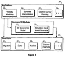
- the role of the geoscience model is to represent the shape and properties of a system under study so that simulation programs may be used to enhance understanding of the system, as shown in Fig. 2.
- a simulation input model generator 30 generates from the geoscience model inputs required for a variety of simulators 32, such as migration 34, sonic 36, nuclear 38, electromagnetic 40 and other types of simulators 42.
- a simulation input model uses the data format required by a simulation program.
- Each simulation program has its own specialized input data format. These formats are specified for a variety of reasons including, but not limited to, run time efficiency, data storage efficiency, numerical methodology, and design history.
- the current generation of simulation programs are based primarily upon the finite element, the finite difference, and ray tracing methods.
- the simulation input model generator provides automated procedures for generating finite difference grids, finite element meshes and tessellated models for ray tracing that may be specialized to a particular simulation program's requirements.
- the continuum assumption states that at a sufficiently large scale material properties, such as porosity and velocity, of a sub-region, which is a portion of a region, can be approximated by macroscopic properties that vary smoothly throughout the sub-region.
- the locations of discontinuities in the material properties, such as at a fault, are called "boundaries.”
- Material property fields and their discontinuities can be represented in a geoscience model which contains the following information:
- the geoscience model and the simulation input models are distinguished so that any number of simulation packages can be supported by a single geoscience model.
- the simulation input models support simulation based interpretation applications.
- ISP models are a representation of smoothly varying material property fields which may contain internal discontinuities that occur along distinct boundaries.
- a discontinuity in a material property occurs where the material property value differs by a finite amount on either side of a discontinuity boundary.
- the location of the discontinuity boundaries make up the shape of the model.
- ISP models explicitly represent the shape of the discontinuity boundaries. These boundaries may lie anywhere in an infinite space, have any shape, and intersect one another to partition space into sets of distinct sub-regions. Within any one sub-region, the material property can be represented by a smoothly varying function.
- the boundaries can be highly irregular in shape and can comprise portions where their shape is fairly uniform (such as a plane or a surface that approximates a plane) and other portions where the boundary is changing rapidly (such as where folding occurs).
- the uniform portions of the boundaries can be represented accurately with fewer parameters. For example, a plane can be represented by three points. In the portions where the boundary is changing rapidly, however, it is necessary to use more parameters to achieve an accurate representation.
- a "hybrid" surface may be made from both a grid and a mesh.
- the grid represents the bulk of the surface (typically the interior) where a high density of points is not necessary.
- the mesh represents the surface boundary areas and surface intersections with other surfaces, curves or points where high density is required.
- the surface is represented with a high density of parameters only where such a representation is necessary. This allows the system to store large surfaces efficiently while maintaining higher accuracy of surface boundaries, when compared to regular grid representations.
- ISP models are also used to model manufactured objects such as acquisition, drilling, and truck equipment, which are represented as solid models. Points in a solid model are classified as being either in or out of the modeled object. In such cases, boundaries are not discontinuities between two regions but the demarcation of the end of the model. In a sense, there is nothing on the other side of a boundary. Solid models do not contain internal boundaries.
- a three-dimensional simulation-based application 50 includes three-dimensional modeling 52 which comprises four basic geoscience model building steps divided into geometry modeling 54 and simulation input model generation 56, as shown in Fig. 3.
- the sequence of shape editing 58, topology model building 60, material property editing 62, and simulation input model generation 56 (which comprises finite element meshing/finite difference gridding/tessellation for ray tracing) defines the scope of geoscience modeling.
- a geoscience model may consist of a combination of a large number of simple geometry primitives. Each geometry primitive is initialized, shaped, and positioned interactively by a user in relationship to the rest of the geoscience model. These geometry primitives include such shapes as lines, circles, planes, free-form surfaces, and solid sub-volumes.
- the shape of a geometry primitive is defined to be the set of points it occupies in space.
- These equations define a map from theta space to [x, y, z] space; that is, for every value of theta there is a unique value of [x, y, z]. Since theta can be any of an infinite number of points the number of points in the circle is also infinite.
- the values ⁇ a, b, c, R ⁇ are called the parameters of the circle. Together, they completely specify all the points that define the circle.
- the functions which represent geometry primitive shapes are all parametric, single valued, continuous functions. These functions have well behaved mathematical properties upon which the algorithms used to build, edit, and query complicated geoscience models depend. Parameterization allows an infinite number of points to be specified by a discrete number of values. Interfaces can be built that conveniently allow the users to edit the parameter values. For example, a pick and drag window-based interface allows a user to select the circle's center point and drag it through space.
- Shape editing is the interactive process of modifying a shape's parameters until it is in a form suitable for use with the rest of the geoscience model.
- the object has only 4 parameters.
- an object may have many more parameters.
- a free-form surface represented as a triangulated mesh can have thousands of parameters.
- the application which helps a user edit the shape of an object with a large number of parameters may very well be a complicated application in itself. But all shape editing applications are dedicated to creating new geometry primitives and setting their parameter values.
- ISP and solid models are built by combining sets of geometry primitives and recording where the primitives intersect one another.
- a user creates a number of surface boundary shapes and uses them to sub-divide space locally to define a set of sub-volumes in a single model. Where boundaries intersect one another, new intersection geometry objects are created to represent the intersection shape and to record the connection among the boundaries.
- sets of boundaries interact to separate one region of space from another, a sub-region object is created for each distinct sub-region. Groups of sub-regions may be used to represent application features such as formations and invasion zones, and boundaries may be used-to represent application features like horizons, faults, and borehole boundaries.
- Geometry objects representing the shape of an application feature are called geometry features.
- FIGs. 4a-c An example of ISP modeling is shown in Figs. 4a-c.
- a volume 70 may be subdivided by two surfaces 72 and 74, as shown in Fig. 4a.
- Another volume 76 representing, for example, a salt dome, may be inserted into the subdivided volume 78 as shown in Fig. 4b.
- the result is a subdivided volume 80 containing a variety of complicated shapes, as shown in Fig. 4c.
- An analyst can mark interesting geometry objects such as the horizons, formed by surfaces 72 and 74, or the salt body 76.
- FIG. 5a An example of solid model building is illustrated Figs. 5a through 5c.
- a series of sub-volumes 82a-d is subtracted from an initial shape 84, as shown in Fig. 5a to produce the volume 86, illustrated in Fig. 5b.
- Additional sub-volumes 88a-c are subtracted from the volume, as shown in Fig. 5B, resulting in a sub-volume 90, shown in Fig. 5C.
- Material property editing is the process of annotating a geoscience model with material properties.
- Material property fields like shape, are represented by functions.
- a parametric function is used to map each point in a modeling image space to a material property value. Any continuous function may be used.
- Some of the more common functions include: constants, constant gradients, and free-form functions (such as triangulated surfaces, poly-lines, NURBS, bi-cubic patches, etc.).
- the shape and topology information in a geoscience model is used to model material property discontinuities.
- Each material property discontinuity is marked by a geometry boundary creating sets of sub-regions in which the material property field is smoothly varying.
- Each sub-region is associated with its own function for representing a common material property field.
- material property discontinuities are represented by using different material functions on either side of a discontinuity boundary. It takes two steps to evaluate the material property at a point within a geoscience model:
- Material property fields may also be defined on region boundaries. These are known as “boundary material properties" as opposed to “region material properties.” Boundary material properties can be associated with the entire boundary or with just one side of the boundary. Oriented boundary material properties may be used to describe boundary value problems.
- the value of a material property at a point is a tensor.
- the tensor may be represented by either a scalar, vector, or matrix quantity. It is a description of properties with intrinsic geometric properties, e.g., it remains invariant under coordinate transformations.
- the components of a high order tensor are stored as a set of scalar values and the applications manage the constraints between component values.
- Material property editing like shape editing, occurs in two ways: building material property fields from data and from scratch. Material property editing consists of:
- Functions are used to represent the boundary shapes which mark the discontinuities within the material property field and map points from a parameter space to a shared image space. Each boundary has its own parameter space but all boundaries share a common image space.
- the parameter space is the domain of the shape function and the shared image space is its range.
- the shared image space is used as the domain for a function which represents a material property field. Every point in the shared image space is projected into a material property value by the material property function.
- a first horizon 100 is represented in parameter space, as shown in Fig. 6a.
- a function, f 1 102 provides a mapping from parameter space to region space.
- the representation 104 of the horizon in region space is shown in Fig. 6b.
- a second horizon 106 is represented in parameter space as shown in Fig. 6c.
- a function, f 2 108 provides a mapping from parameter space to region space.
- the representation 110 of the horizon in region space is shown in Fig. 6d.
- the subdivision of the region by the first horizon 104 and the second horizon 110 forms three subregions 112, 114, 116, as shown in Fig. 6e.
- Region 112 is the subregion below horizon 110.
- Region 114 is the region between the two horizons, and region 116 is the region above horizon 104.
- a material property, MP is assigned a value represented by the function MP 1 118 in region 112. The material property is assigned a different function, MP 2 120, in region 114.
- a representation of the value of MP 122 in region 112 is shown in Fig. 6f.
- a representation of material property MP 124 in region 114 is shown in Fig. 6g.
- the process of simulation input model generation consists of an interactive phase in which the user specifies the size, location, and properties of a mesh or grid to be stored in a simulation input model description.
- the interactive phase is followed by an automated phase in which the simulation input model is built given the geoscience model and simulation input model description.
- the invention may be implemented in hardware or software, or a combination of both. However, preferably, the invention is implemented in computer programs executing on programmable computers each comprising a processor, a data storage system (including volatile and non-volatile memory and/or storage elements), at least one input device, and at least one output device. Program code is applied to input data to perform the functions described above and generate output information. The output information is applied to one or more output devices, in known fashion.
- Each program is preferably implemented in a high level procedural or object oriented programming language (such as C++ or C) to communicate with a computer system.
- the programs can be implemented in assembly or machine language, if desired.
- the language may be a compiled or an interpreted language.
- Each such computer program is preferably stored on a storage media or device (e.g. , ROM or magnetic/optical disk or diskette) readable by a general or special purpose programmable computer, for configuring and operating the computer when the storage media or device is read by the computer to perform the procedures described herein.
- a storage media or device e.g. , ROM or magnetic/optical disk or diskette
- the inventive system may also be considered to be implemented as a computer-readable storage medium, configured with a computer program, where the storage medium so configured causes a computer to operate in a specific and predefined manner to perform the functions described herein.
Landscapes
- Physics & Mathematics (AREA)
- Life Sciences & Earth Sciences (AREA)
- Engineering & Computer Science (AREA)
- Remote Sensing (AREA)
- General Life Sciences & Earth Sciences (AREA)
- General Physics & Mathematics (AREA)
- Geophysics (AREA)
- Acoustics & Sound (AREA)
- Environmental & Geological Engineering (AREA)
- Geology (AREA)
- Management, Administration, Business Operations System, And Electronic Commerce (AREA)
- Geophysics And Detection Of Objects (AREA)
Description
- This invention relates to performing geoscience interpretation with simulated data.
- Geologists, geophysicists, petroleum engineers and production engineers use models, including computerized models, of the earth's shell to plan exploration and production of hydrocarbons and, to a lesser extent, other minerals. As hydrocarbons become more and more scarce, the accuracy of the computerized models becomes increasingly important to limiting the cost of locating and producing hydrocarbons and the associated cost of hydrocarbon products, such as gasoline and heating oil.
- Existing modeling systems use an "inversion" technique to model geoscience structures from acquired data. Acquired data, such as velocity measurements or data collected through seismic instrumentation, is "inverted" and used to predict the location of subsurface structures and the physical properties of those subsurface structures.
- Once the inversion process produces predictions of the locations and physical properties of the subsurface structures, they are modeled geometrically. Such models must be capable of representing complicated geometrical shapes, such as the shape of a salt dome or salt wall or the shape of a group of folded sedimentary beds.
- Commonly, modeling systems use a grid system to represent subsurface structures. In a grid system, the subsurface structures are represented by points in space regularly spaced in the x-y plane and having a single value in the z plane. The values corresponding to those subsurface structures between the regularly-spaced points are determined by interpolation. In a model for a large subsurface region, the number of points in space can be numerous, requiring a great deal of storage, even if the subsurface structures are uniform in topography and physical properties across that space.
- Another modeling system that has been applied to the problem of modeling subsurface structures is constructional solid geometry ("CSG"). Under this approach, two or more solid primitives (such as cylinders or spheres) are combined to form a more complicated solid. The process begins with objects chat are known to be solid and adds or subtracts other solids to create new shapes. For example, subtracting a cylinder from a box will produce a box with a hole in it.
- Several solutions exist that attempt to conform a lithology model to observed data. One approach is to compare results from simulations carried out on the model to actual observed results. If these do not correspond, the model is adjusted until a better correspondence is achieved. U.S. Patent 4,679,174 to Gelfand describes that technique used to adjust a lithology model storing parameters such as velocity, density, and layer thickness in order to obtain a desired degree of correspondence between synthetic reflection data and gathered seismic data. U.S. Patent 4,969,130 to Wasson et al. describes a technique of conforming a reservoir model by adjusting the model so that the model accurately predicts the seismic response observed from seismic surveys.
- U.S. Patent 5,229,976 to Boyd et al. teaches a method for creating a digital two-dimensional model of a drawn or-imaged model of the subsurface physical properties. In Boyd, geological horizons and faults are digitized and a two-dimensional cellular model is created.
- Neff et al., in European Patent Application EP 0 745 870 A2, describe a method of generating a reservoir model using both seismic and lithologic data. Neff observes that a given seismic trace may correspond to many different geologic formations. Nell calculates pseudo-logs at locations away from an existing well and corresponding to an initial model which takes into account both observed seismic data and petrophysical data obtained from the well. These pseudo-logs are computed using several possible models by using forward model perturbation techniques. Synthetic traces are then computed based on these pseudo-logs. These synthetic traces are then compared to observed seismic traces to determine which synthetic seismic trace has the best fit to the observed seismic data and the corresponding pseudo-logs are used to assign petrophysical properties for a display model.
- The invention comprises a method as defined in
claim 1, a computer program is defined in claim 13, as well as a computer system as defined in claim 7. - In general, in one aspect, the invention features a method for analyzing geological data stored in a geoscience model on a magnetic media, comprising building a simulation input model from the geoscience model.
- Implementations of the invention may include one or more of the following. The method may further comprise acquiring data; interpreting the acquired data to produce the geoscience model; applying a simulator to the simulation input model to produce synthetic data; comparing the acquired data to the synthetic data to produce a difference; and editing the geoscience model to reduce the difference. The simulator may comprise a simulation program used to develop acquisition equipment. Building the simulation model may comprise producing a finite element mesh. Building the simulation model may comprise producing a finite difference grid. Building the simulation input model may comprise producing a tessellated model. The simulation input model may have a different format than the geoscience model.
- In general, in another aspect, the invention features a method for analyzing geological data representing a subsurface region, the geological data being stored in a geoscience model on a magnetic media, comprising constructing a boundary for dividing the region into a first sub-region and a second sub-region; storing on the magnetic media the shape of the boundary as a parametric function whose parameter density can vary.
- In general, in another aspect, the invention features a method for analyzing geological data sampled from a subsurface region, the geological data and an analysis of the geological data being stored in a geoscience model on a magnetic media, the method comprising dividing the region into sub-regions, in each of which a material property varies without discontinuities.
- Implementation of the invention may include one or more of the following. The method may further comprise describing the variation of the material property with a parametric function.
- In general, in another aspect, the invention features a computer system for analyzing geological data stored in a geoscience model on a computer-readable. magnetic media, comprising means for building a simulation input model from the geoscience model.
- Implementations of the invention may include one or more of the following. The computer system may further comprise means for acquiring data; means for interpreting the acquired data to produce the geoscience model; means for applying a simulator to the simulation input model to produce synthetic data; means for comparing the acquired data to the synthetic data to produce a difference; and means for editing the geoscience model to reduce the difference. The simulator may comprise a simulation program used to develop acquisition equipment. The means for building the simulation input model may comprise a means for producing a finite element mesh. The means for building the simulation data input model may comprise a means for producing a finite difference grid. The means for building the simulation input model may comprise a means for producing a tessellated model. The simulation input model may have a different format than the geoscience model.
- In general, in another aspect, the invention features a computer system for analyzing geological data sampled from a subsurface region, the geological data and an analysis of the geological data being stored in a geoscience model on a computer-readable magnetic media, comprising means for constructing a boundary for dividing the region into a first sub-region and a second sub-region; means for storing on the magnetic media the shape of the boundary as a parametric function whose parameter density can vary.
- In general, in another aspect, the invention features a computer system for analyzing geological data sampled from a subsurface region, the geological data and an analysis of the geological data being stored in a geoscience model on a magnetic media, the computer system comprising means for dividing the region into sub-regions, in each of which a material property varies without discontinuities.
- In general, in another aspect, the invention features a computer program, residing on a computer-readable medium, for analyzing geological data sampled from a subsurface region and an analysis of the geological data stored in a geoscience model on a magnetic media, comprising instructions for causing a computer to build a simulation input model from the geoscience model.
- Implementations of the invention may include one or more of the following. The computer program may further comprise instructions for causing the computer to acquire data; interpret the acquired data to produce the geoscience model; apply a simulator to the simulation input model to produce synthetic data; compare the acquired data to the synthetic data to produce a difference; and edit the geoscience model to reduce the difference. The simulator may comprise a simulation program used to develop acquisition equipment. The instructions which cause the computer to build the simulation input model may comprise instructions which cause the computer to produce a finite element mesh. The instructions which cause the computer to build the simulation input model may comprise instructions which cause the computer to produce a finite difference grid. The instructions which cause the computer to build the simulation input model may comprise instructions which cause the computer to produce a tessellated model. The simulation input model may have a different format than the geoscience model.
- In general, in another aspect, the invention features a computer program, residing on a computer-readable medium, for analyzing geological data sampled from a subsurface region, the geological data and an analysis of the geological data being stored in a geoscience model on a magnetic media, comprising instructions for causing a computer to construct a boundary for dividing the region into a first sub-region and a second sub-region; store on the magnetic media the shape of the boundary as a parametric function whose parameter density can vary.
- In general, in another aspect, the invention features a computer program, stored on a computer-readable medium, for analyzing geological data sampled from a subsurface region, the geological data and an analysis of the geological data being stored in a geoscience model on a magnetic media, the computer program comprising instructions for causing a computer to divide the region into sub-regions, in each of which a material property varies without discontinuities.
- Figs. 1-3 are block diagrams.
- Figs. 4a-c, 5a-c and 6a-g are representations of modeled items.
- Simulation based interpretation ("SBI"), illustrated in Fig. 1, is an alternative to the inversion process for producing consistent models from acquired data. SBI begins by gathering acquired
data 10 from the geologic structures being modeled. The acquired data is interpreted and the resulting interpretation is captured as ageoscience model 12. The model is then tested by simulating an original acquisition experiment to producesynthetic data 14. For example, the simulation programs used to develop acquisition equipment can be used to produce the synthetic data. Differences between thesynthetic data 14 and the acquireddata 10 are determined and used to adjust the model. Repeated iterations of these steps may cause the model to converge toward a consistent model in which the differences between the synthetic and the acquired data are reduced. Making a single interpretation consistent with several measurements from a variety of experiments at one time continues to improve the quality of the interpretation. Trained interpreters can use such a system interactively to build interpretations which can be relied upon for prediction purposes. - The
geoscience model 12 is a permanent repository of the interpretation which is stored in a general format so that input for a variety of simulators can be generated from it. The geoscience model is editable so that interpreters can quickly converge the model to a consistent interpretation. Once the geoscience model exists and has been verified as consistent with existing data, it can be used for a variety of predictive and planning purposes such as survey planning, estimating reservoir performance, and well completion planning. - The same technologies needed to support simulation based interpretation can be used to improve the process for designing acquisition equipment. Equipment models placed within geoscience models may be used to build simulation input models for simulators. Simulation outputs are analyzed and compared to design specifications. Design alternatives and parameter variations can be quickly tested and optimized prior to building the first prototype.
- The same technologies needed to support simulation based interpretation can be used to improve the quality of acquired data by improving the process of survey planning. Source and receiving equipment models placed in geoscience models may be used to generate simulation input models for simulators. Simulation outputs may be analyzed and used to optimize the placement of the sources and receivers.
- One part of the geoscience model is a geometric representation of a portion of the earth's subsurface. In geoscience applications, known geometric primitives, such as spheres and cylinders, are less useful than in other applications. While the underground structures may have started out their geological life capable of being described as simple geometric primitives, over time most have become distorted and are not easily represented using a grid system or a constructional solid geometry system. For example, if a set of sedimentary beds folds over on top of itself, a single x-y point will have two or more z values for a given bed. Further, the shapes are very complicated and not easily represented using CSG primitives.
- The role of the geoscience model is to represent the shape and properties of a system under study so that simulation programs may be used to enhance understanding of the system, as shown in Fig. 2. A variety of
3D modeling applications 20 includingvelocity modeling 22, borehole interpretation 24,seismic planning 26, andothers 28, share acommon geoscience model 12. A simulationinput model generator 30 generates from the geoscience model inputs required for a variety ofsimulators 32, such asmigration 34, sonic 36, nuclear 38, electromagnetic 40 and other types ofsimulators 42. - A simulation input model uses the data format required by a simulation program. Each simulation program has its own specialized input data format. These formats are specified for a variety of reasons including, but not limited to, run time efficiency, data storage efficiency, numerical methodology, and design history.
- The current generation of simulation programs are based primarily upon the finite element, the finite difference, and ray tracing methods. The simulation input model generator provides automated procedures for generating finite difference grids, finite element meshes and tessellated models for ray tracing that may be specialized to a particular simulation program's requirements.
- The domain of the geoscience model is defined by the simulation programs it is required to support. Despite the many different physical phenomena that the simulators model, they all have the following in common:
- (a) the continuum assumption;
- (b) a representation of distributed material properties;
- (c) a set of shared simulation techniques including the finite element, finite difference, and ray tracing methods.
-
- The continuum assumption states that at a sufficiently large scale material properties, such as porosity and velocity, of a sub-region, which is a portion of a region, can be approximated by macroscopic properties that vary smoothly throughout the sub-region. The locations of discontinuities in the material properties, such as at a fault, are called "boundaries." Material property fields and their discontinuities can be represented in a geoscience model which contains the following information:
- (a) Shape, which is defined to be the location of the discontinuity boundaries;
- (b) Topology, which is defined to be the connections between boundaries and sub-regions;
- (c) Material properties, which are defined to be smoothly varying values within and on the boundaries of each sub-region and boundary object; and
- (d) Simulation input models, which are defined to be an extraction of the information in a geoscience model in a form suitable for use by a simulation package.
-
- The geoscience model and the simulation input models are distinguished so that any number of simulation packages can be supported by a single geoscience model. The simulation input models support simulation based interpretation applications.
- Irregular space partition ("ISP") models are a representation of smoothly varying material property fields which may contain internal discontinuities that occur along distinct boundaries. A discontinuity in a material property occurs where the material property value differs by a finite amount on either side of a discontinuity boundary. The location of the discontinuity boundaries make up the shape of the model. ISP models explicitly represent the shape of the discontinuity boundaries. These boundaries may lie anywhere in an infinite space, have any shape, and intersect one another to partition space into sets of distinct sub-regions. Within any one sub-region, the material property can be represented by a smoothly varying function.
- The boundaries can be highly irregular in shape and can comprise portions where their shape is fairly uniform (such as a plane or a surface that approximates a plane) and other portions where the boundary is changing rapidly (such as where folding occurs). The uniform portions of the boundaries can be represented accurately with fewer parameters. For example, a plane can be represented by three points. In the portions where the boundary is changing rapidly, however, it is necessary to use more parameters to achieve an accurate representation.
- For example, a "hybrid" surface may be made from both a grid and a mesh. The grid represents the bulk of the surface (typically the interior) where a high density of points is not necessary. The mesh represents the surface boundary areas and surface intersections with other surfaces, curves or points where high density is required. Thus, the surface is represented with a high density of parameters only where such a representation is necessary. This allows the system to store large surfaces efficiently while maintaining higher accuracy of surface boundaries, when compared to regular grid representations.
- ISP models are also used to model manufactured objects such as acquisition, drilling, and truck equipment, which are represented as solid models. Points in a solid model are classified as being either in or out of the modeled object. In such cases, boundaries are not discontinuities between two regions but the demarcation of the end of the model. In a sense, there is nothing on the other side of a boundary. Solid models do not contain internal boundaries.
- A three-dimensional simulation-based
application 50 includes three-dimensional modeling 52 which comprises four basic geoscience model building steps divided intogeometry modeling 54 and simulationinput model generation 56, as shown in Fig. 3. The sequence ofshape editing 58,topology model building 60,material property editing 62, and simulation input model generation 56 (which comprises finite element meshing/finite difference gridding/tessellation for ray tracing) defines the scope of geoscience modeling. - As discussed above, a geoscience model may consist of a combination of a large number of simple geometry primitives. Each geometry primitive is initialized, shaped, and positioned interactively by a user in relationship to the rest of the geoscience model. These geometry primitives include such shapes as lines, circles, planes, free-form surfaces, and solid sub-volumes.
- The shape of a geometry primitive is defined to be the set of points it occupies in space. For example, a circle of radius R, lying in a plane parallel to the x-y plane and centered on the point [a, b, c] is the set of points given by the function
- The values {a, b, c, R} are called the parameters of the circle. Together, they completely specify all the points that define the circle. The functions which represent geometry primitive shapes are all parametric, single valued, continuous functions. These functions have well behaved mathematical properties upon which the algorithms used to build, edit, and query complicated geoscience models depend. Parameterization allows an infinite number of points to be specified by a discrete number of values. Interfaces can be built that conveniently allow the users to edit the parameter values. For example, a pick and drag window-based interface allows a user to select the circle's center point and drag it through space. The code that implements this behavior has only to convert the mouse's position into a spatial (x, y, z) location and use those values to change the shape of the circle, e.g. a = x, b = y, c = z.
- Shape editing is the interactive process of modifying a shape's parameters until it is in a form suitable for use with the rest of the geoscience model. In the circle example, the object has only 4 parameters. In general, an object may have many more parameters. For example, a free-form surface represented as a triangulated mesh can have thousands of parameters. The application which helps a user edit the shape of an object with a large number of parameters may very well be a complicated application in itself. But all shape editing applications are dedicated to creating new geometry primitives and setting their parameter values.
- There are two kinds of shape editing applications: those that extract shapes from data, and those that build shapes from scratch. Extracting shape from data is a user directed semi-automated process, while building shape definitions from scratch is interactive.
- ISP and solid models are built by combining sets of geometry primitives and recording where the primitives intersect one another. In three-dimensional ISP building, a user creates a number of surface boundary shapes and uses them to sub-divide space locally to define a set of sub-volumes in a single model. Where boundaries intersect one another, new intersection geometry objects are created to represent the intersection shape and to record the connection among the boundaries. When sets of boundaries interact to separate one region of space from another, a sub-region object is created for each distinct sub-region. Groups of sub-regions may be used to represent application features such as formations and invasion zones, and boundaries may be used-to represent application features like horizons, faults, and borehole boundaries. Not every object in a geoscience model is used to represent an application feature, but every application feature with a geometric description is associated with a geometry object. Geometry objects representing the shape of an application feature are called geometry features.
- Building solid models is very similar to building ISP models. In solid modeling, the user builds a sequence of solid shapes and combines them together with the standard boolean operators of union, subtract, and intersect to create accurate representations of complicated machined metal solids. The side effect of editing the topology structure representation when combining primitives into ISP and solid models is automated. Sequences for building ISP and solid models may use the subdivide, insert, and subtract operators, which are just a few of the topology editing operators to be found in a general geometry modeling application and which are described in detail in co-pending application serial number , entitled "Modeling Geological Structures and Properties," incorporated by reference.
- An example of ISP modeling is shown in Figs. 4a-c. A
volume 70 may be subdivided by twosurfaces volume 76, representing, for example, a salt dome, may be inserted into the subdividedvolume 78 as shown in Fig. 4b. The result is a subdividedvolume 80 containing a variety of complicated shapes, as shown in Fig. 4c. An analyst can mark interesting geometry objects such as the horizons, formed bysurfaces salt body 76. - An example of solid model building is illustrated Figs. 5a through 5c. A series of sub-volumes 82a-d is subtracted from an
initial shape 84, as shown in Fig. 5a to produce thevolume 86, illustrated in Fig. 5b. Additional sub-volumes 88a-c are subtracted from the volume, as shown in Fig. 5B, resulting in a sub-volume 90, shown in Fig. 5C. - Material property editing is the process of annotating a geoscience model with material properties. Material property fields, like shape, are represented by functions. A parametric function is used to map each point in a modeling image space to a material property value. Any continuous function may be used. Some of the more common functions include: constants, constant gradients, and free-form functions (such as triangulated surfaces, poly-lines, NURBS, bi-cubic patches, etc.).
- The shape and topology information in a geoscience model is used to model material property discontinuities. Each material property discontinuity is marked by a geometry boundary creating sets of sub-regions in which the material property field is smoothly varying. Each sub-region is associated with its own function for representing a common material property field. Thus, material property discontinuities are represented by using different material functions on either side of a discontinuity boundary. It takes two steps to evaluate the material property at a point within a geoscience model:
- (a) find the sub-region containing the point and its associated material property function; and
- (b) evaluate the sub-region's material property function at the required point. Any number of material property fields can be represented in a geoscience model by storing one parametric function for each material property in each sub-region.
-
- Material property fields may also be defined on region boundaries. These are known as "boundary material properties" as opposed to "region material properties." Boundary material properties can be associated with the entire boundary or with just one side of the boundary. Oriented boundary material properties may be used to describe boundary value problems.
- The value of a material property at a point is a tensor. The tensor may be represented by either a scalar, vector, or matrix quantity. It is a description of properties with intrinsic geometric properties, e.g., it remains invariant under coordinate transformations. The components of a tensor are represented in a chosen coordinate system. Changing the coordinate system changes the values of the coordinates. Relationships between tensor quantities as defined by fundamental physical laws are independent of coordinate transformations. For example, Newton's law defines the relationship between acceleration, A, and force, F, as, F = mA, which defines the quantity mass, m. This relationship is true independent of which coordinate system is chosen to describe the components of the tensor quantities F, m, and A. In this system, there is no special accommodation for tensors. The components of a high order tensor are stored as a set of scalar values and the applications manage the constraints between component values.
- Material property editing, like shape editing, occurs in two ways: building material property fields from data and from scratch. Material property editing consists of:
- (a) Specifying the set of material properties to be represented in the geoscience model.
- (b) Selecting and assigning a parametric function
for each material property
in each sub-region, and optionally
in each boundary, and
on each side of a boundary. - (c) Editing the parameters of the material property parametric functions as desired.
-
- Representing a material property field in an ISP geoscience model is done by using functions. Functions are used to represent the boundary shapes which mark the discontinuities within the material property field and map points from a parameter space to a shared image space. Each boundary has its own parameter space but all boundaries share a common image space. The parameter space is the domain of the shape function and the shared image space is its range. The shared image space is used as the domain for a function which represents a material property field. Every point in the shared image space is projected into a material property value by the material property function.
- The steps used to subdivide a volume and assign material properties to the volume are illustrated in Figs. 6a-g. A
first horizon 100 is represented in parameter space, as shown in Fig. 6a. A function,f 1 102, provides a mapping from parameter space to region space. Therepresentation 104 of the horizon in region space is shown in Fig. 6b. Similarly, asecond horizon 106 is represented in parameter space as shown in Fig. 6c. A function,f 2 108, provides a mapping from parameter space to region space. Therepresentation 110 of the horizon in region space is shown in Fig. 6d. The subdivision of the region by thefirst horizon 104 and thesecond horizon 110 forms threesubregions Region 112 is the subregion belowhorizon 110.Region 114 is the region between the two horizons, andregion 116 is the region abovehorizon 104. A material property, MP, is assigned a value represented by thefunction MP 1 118 inregion 112. The material property is assigned a different function,MP 2 120, inregion 114. A representation of the value ofMP 122 inregion 112 is shown in Fig. 6f. A representation ofmaterial property MP 124 inregion 114 is shown in Fig. 6g. - The process of simulation input model generation consists of an interactive phase in which the user specifies the size, location, and properties of a mesh or grid to be stored in a simulation input model description. The interactive phase is followed by an automated phase in which the simulation input model is built given the geoscience model and simulation input model description.
- The invention may be implemented in hardware or software, or a combination of both. However, preferably, the invention is implemented in computer programs executing on programmable computers each comprising a processor, a data storage system (including volatile and non-volatile memory and/or storage elements), at least one input device, and at least one output device. Program code is applied to input data to perform the functions described above and generate output information. The output information is applied to one or more output devices, in known fashion.
- Each program is preferably implemented in a high level procedural or object oriented programming language (such as C++ or C) to communicate with a computer system. However, the programs can be implemented in assembly or machine language, if desired. In any case, the language may be a compiled or an interpreted language.
- Each such computer program is preferably stored on a storage media or device (e.g., ROM or magnetic/optical disk or diskette) readable by a general or special purpose programmable computer, for configuring and operating the computer when the storage media or device is read by the computer to perform the procedures described herein. The inventive system may also be considered to be implemented as a computer-readable storage medium, configured with a computer program, where the storage medium so configured causes a computer to operate in a specific and predefined manner to perform the functions described herein.
- Other embodiments are within the scope of the following claims.
Claims (18)
- A method for analyzing geological data acquired from a subsurface region and an analysis of the geological data being stored in a geoscience model on a magnetic medium, the method comprising
interpreting the acquired data to produce the geoscience model;
building a simulation input model from the geoscience model;
applying an original acquisition experiment simulator to the simulation input model to produce synthetic data; and
comparing the acquired data to the synthetic data to produce a difference;
wherein the method further comprises:dividing the subsurface region into a first sub-region and a second sub-region by constructing a boundary between the sub-regions and wherein within each sub-region a material property varies without discontinuities;describing the variation of the material property within a sub-region with a parametric function;storing on the magnetic medium the shape of the boundary as a plurality of parametric functions whose parameter density can vary; andediting the geoscience model to reduce the difference between the acquired data and the synthetic data. - The method of claim 1, wherein the simulator comprises a simulation program used to develop acquisition equipment.
- The method of claim 1 or 2, wherein building the simulation input model comprises producing a finite element mesh.
- The method of claim 1 or 2, wherein building the simulation input model comprises producing a finite difference grid.
- The method of claim 1 or 2, wherein building the simulation input model comprises producing a tessellated model.
- The method of any preceding claim, wherein the simulation input model has a different format than the geoscience model.
- A computer system for analyzing geological data stored in a geoscience model on a computer-readable magnetic medium, the system comprising:wherein the computer system further comprises:means for acquiring data;means for interpreting the acquired data to produce the geoscience model;means for building a simulation input model from the geoscience model;means for applying an original acquisition experiment simulator to the simulation input model to produce synthetic data;means for comparing the acquired data to the synthetic data to produce a difference;means for dividing the region into a first sub-region and a second sub-region by constructing a boundary between the sub-regions and wherein within each sub-region a material property varies without discontinuities;means for describing the variation of the material property within a sub-region with a parametric function;means for storing on the magnetic media the shape of the boundary as a plurality of parametric functions whose parameter density can vary; andmeans for editing the geoscience model to reduce the difference between the acquired data and the synthetic data.
- The computer system of claim 7, wherein the simulator comprises a simulation program used to develop acquisition equipment.
- The computer system of claim 7 or 8, wherein the means for building the simulation model comprises a means for producing a finite element mesh.
- The computer system of claim 7 or 8, wherein the means for building the simulation model comprises a means for producing a finite difference grid.
- The computer system of claim 7 or 8, wherein the means for building the simulated model comprises a means for producing a tessellated model.
- The computer system of any one of claims 7 to 11,
wherein the simulation input model has a different format than the geoscience model. - A computer program storage device comprising a computer-readable medium, having stored thereon a computer program for analyzing geological data sampled from a subsurface region, the geological data and an analysis of the geological data being stored in a geoscience model on a magnetic medium, said program including instructions for causing a computer to:wherein the program further comprises instructions for causing the computer to:acquire geological data;interpret the acquired date to produce the geoscience model;build a simulation input model from the geoscience model;apply an original acquisition experiment simulator to the simulation input model to produce synthetic data;compare the acquired data to the synthetic data to produce a difference;divide the region into a first sub-region and a second sub-region by constructing a boundary between the sub-regions and wherein within each sub-region a material property varies without discontinuities;model the variation of the material property within a sub-region with a parametric function;store on the magnetic media the shape of the boundary as a plurality of parametric functions whose parameter density can vary; andedit the geoscience model to reduce the difference.
- The computer program storage device of claim 13, wherein the simulator comprises a simulation program used to develop acquisition equipment.
- The computer program storage device of claim 13 or 14, wherein the instructions which cause the computer to build the simulation input model comprise instructions which cause the computer to produce a finite element mesh.
- The computer program storage device of claim 13 or 14, wherein the instructions which cause the computer to build the simulation input model comprise instructions which cause the computer to produce a finite difference grid.
- The computer program storage device of claim 13 or 14, wherein the instructions which cause the computer to build the simulation input model comprise instructions which cause the computer to produce a tessellated model.
- The computer program storage device of any one of claims 13 through 17, wherein the simulation input model has a different format than the geoscience model.
Applications Claiming Priority (3)
| Application Number | Priority Date | Filing Date | Title |
|---|---|---|---|
| US08/770,209 US5905657A (en) | 1996-12-19 | 1996-12-19 | Performing geoscience interpretation with simulated data |
| US770209 | 1996-12-19 | ||
| PCT/US1997/024279 WO1998027444A2 (en) | 1996-12-19 | 1997-12-18 | Performing geoscience interpretation with simulated data |
Publications (2)
| Publication Number | Publication Date |
|---|---|
| EP0951652A2 EP0951652A2 (en) | 1999-10-27 |
| EP0951652B1 true EP0951652B1 (en) | 2003-10-08 |
Family
ID=25087807
Family Applications (1)
| Application Number | Title | Priority Date | Filing Date |
|---|---|---|---|
| EP97952696A Expired - Lifetime EP0951652B1 (en) | 1996-12-19 | 1997-12-18 | Performing geoscience interpretation with simulated data |
Country Status (5)
| Country | Link |
|---|---|
| US (2) | US5905657A (en) |
| EP (1) | EP0951652B1 (en) |
| CA (1) | CA2275398C (en) |
| DE (1) | DE69725468T2 (en) |
| WO (1) | WO1998027444A2 (en) |
Families Citing this family (144)
| Publication number | Priority date | Publication date | Assignee | Title |
|---|---|---|---|---|
| US6106561A (en) * | 1997-06-23 | 2000-08-22 | Schlumberger Technology Corporation | Simulation gridding method and apparatus including a structured areal gridder adapted for use by a reservoir simulator |
| US6191787B1 (en) | 1998-02-10 | 2001-02-20 | Schlumberger Technology Corporation | Interactively constructing, editing, rendering and manipulating geoscience models |
| US6313837B1 (en) | 1998-09-29 | 2001-11-06 | Schlumberger Technology Corporation | Modeling at more than one level of resolution |
| EP1151326B1 (en) | 1999-02-12 | 2005-11-02 | Schlumberger Limited | Uncertainty constrained subsurface modeling |
| US6442488B2 (en) | 1999-03-08 | 2002-08-27 | Baker Hughes Incorporated | Inhomogeneous background based focusing method for multiarray induction measurements in a deviated well |
| US6219619B1 (en) * | 1999-03-08 | 2001-04-17 | Baker Hughes Incorporated | Inhomogeneous background-based software focusing method for array-type induction logging tools |
| US6658567B1 (en) | 1999-06-25 | 2003-12-02 | Geomechanics International, Inc. | Method and logic for locking geological data and an analyzer program that analyzes the geological data |
| AU7911800A (en) * | 1999-09-30 | 2001-04-30 | Shell Internationale Research Maatschappij B.V. | Method and apparatus for multi-dimensional data modelling and analysis using a haptic interface device |
| GB2354852B (en) * | 1999-10-01 | 2001-11-28 | Schlumberger Holdings | Method for updating an earth model using measurements gathered during borehole construction |
| US6480790B1 (en) | 1999-10-29 | 2002-11-12 | Exxonmobil Upstream Research Company | Process for constructing three-dimensional geologic models having adjustable geologic interfaces |
| US6928399B1 (en) | 1999-12-03 | 2005-08-09 | Exxonmobil Upstream Research Company | Method and program for simulating a physical system using object-oriented programming |
| AU2001251019A1 (en) * | 2000-03-27 | 2001-10-08 | Peter J. Ortoleva | Method for simulation of enhanced fracture detection in sedimentary basins |
| US7415401B2 (en) * | 2000-08-31 | 2008-08-19 | Exxonmobil Upstream Research Company | Method for constructing 3-D geologic models by combining multiple frequency passbands |
| US6680735B1 (en) * | 2000-10-04 | 2004-01-20 | Terarecon, Inc. | Method for correcting gradients of irregular spaced graphic data |
| US6917907B2 (en) * | 2000-11-29 | 2005-07-12 | Visteon Global Technologies, Inc. | Method of power steering hose assembly design and analysis |
| WO2002047011A1 (en) * | 2000-12-08 | 2002-06-13 | Ortoleva Peter J | Methods for modeling multi-dimensional domains using information theory to resolve gaps in data and in theories |
| GB0125713D0 (en) * | 2001-10-26 | 2001-12-19 | Statoil Asa | Method of combining spatial models |
| US6968909B2 (en) * | 2002-03-06 | 2005-11-29 | Schlumberger Technology Corporation | Realtime control of a drilling system using the output from combination of an earth model and a drilling process model |
| US7689396B2 (en) * | 2002-05-24 | 2010-03-30 | Pgs Americas, Inc. | Targeted geophysical survey |
| AU2003245762B2 (en) * | 2002-06-28 | 2008-01-31 | Gedex Inc. | System and method for surveying underground density distributions |
| GB2390904B (en) * | 2002-07-16 | 2004-12-15 | Univ Southampton | Electromagnetic surveying for hydrocarbon reservoirs |
| US20040148144A1 (en) * | 2003-01-24 | 2004-07-29 | Martin Gregory D. | Parameterizing a steady-state model using derivative constraints |
| US7899657B2 (en) * | 2003-01-24 | 2011-03-01 | Rockwell Automoation Technologies, Inc. | Modeling in-situ reservoirs with derivative constraints |
| WO2004081879A1 (en) * | 2003-03-14 | 2004-09-23 | Castanon Fernandez Cesar | Method of determining the physicochemical properties of a three-dimensional body |
| GB2402745B (en) * | 2003-06-10 | 2005-08-24 | Activeem Ltd | Electromagnetic surveying for hydrocarbon reservoirs |
| NL1024444C2 (en) * | 2003-10-03 | 2005-04-08 | J O A Beheer B V | Method, device, computer program and data carrier for modeling a multi-dimensional heterogeneous structure with a digital processing unit. |
| EP1711904A4 (en) * | 2003-12-19 | 2010-02-10 | Esi Group | Methods for generating digital or visual representations of a closed tessellated surface geometry |
| GB2409900B (en) | 2004-01-09 | 2006-05-24 | Statoil Asa | Processing seismic data representing a physical system |
| US20050165555A1 (en) * | 2004-01-13 | 2005-07-28 | Baker Hughes Incorporated | 3-D visualized data set for all types of reservoir data |
| WO2005121840A1 (en) * | 2004-06-07 | 2005-12-22 | Exxonmobil Upstream Research Company | Method for solving implicit reservoir simulation matrix equation |
| US7908313B2 (en) * | 2004-07-21 | 2011-03-15 | The Mathworks, Inc. | Instrument-based distributed computing systems |
| US7454659B1 (en) * | 2004-08-24 | 2008-11-18 | The Mathworks, Inc. | Distributed systems in test environments |
| US7941307B2 (en) * | 2004-11-10 | 2011-05-10 | Exxonmobil Upstream Research Company | Method for calibrating a model of in-situ formation stress distribution |
| EP1836624A4 (en) * | 2004-11-29 | 2010-12-22 | Chevron Usa Inc | Method, system and program storage device for simulating fluid flow in a physical system using a dynamic composition based extensible object-oriented architecture |
| US7373251B2 (en) * | 2004-12-22 | 2008-05-13 | Marathon Oil Company | Method for predicting quantitative values of a rock or fluid property in a reservoir using seismic data |
| GB2422673B (en) * | 2005-02-01 | 2010-03-24 | Electromagnetic Geoservices As | Optimum signal for sea bed logging |
| US7894989B2 (en) * | 2005-06-09 | 2011-02-22 | Exxonmobil Upstream Research Co. | Method for determining earth vertical electrical anisotropy in marine electromagnetic surveys |
| US7692649B2 (en) | 2005-10-04 | 2010-04-06 | Rdv Systems Ltd. | Method and apparatus for virtual reality presentation of civil engineering, land planning and infrastructure |
| US7978192B2 (en) * | 2005-10-04 | 2011-07-12 | Rdv Systems Ltd. | Method and apparatus for evaluating sight distance |
| GB2435693A (en) * | 2006-02-09 | 2007-09-05 | Electromagnetic Geoservices As | Seabed electromagnetic surveying |
| WO2007126676A2 (en) | 2006-04-21 | 2007-11-08 | Exxonmobil Upstream Research Company | In situ co-development of oil shale with mineral recovery |
| US7660711B2 (en) * | 2006-04-28 | 2010-02-09 | Saudi Arabian Oil Company | Automated event monitoring system for online reservoir simulation |
| US7620534B2 (en) * | 2006-04-28 | 2009-11-17 | Saudi Aramco | Sound enabling computerized system for real time reservoir model calibration using field surveillance data |
| GB2439378B (en) * | 2006-06-09 | 2011-03-16 | Electromagnetic Geoservices As | Instrument for measuring electromagnetic signals |
| CA2663662C (en) * | 2006-09-13 | 2016-07-05 | Exxonmobil Upstream Research Company | Rapid inversion of electromagnetic reconnaissance survey data |
| GB2442749B (en) | 2006-10-12 | 2010-05-19 | Electromagnetic Geoservices As | Positioning system |
| CN101563524B (en) | 2006-10-13 | 2013-02-27 | 埃克森美孚上游研究公司 | Combined development of oil shale by in situ heating with a deeper hydrocarbon resource |
| AU2007313396B2 (en) | 2006-10-13 | 2013-08-15 | Exxonmobil Upstream Research Company | Optimized well spacing for in situ shale oil development |
| AU2007313393B2 (en) | 2006-10-13 | 2013-08-15 | Exxonmobil Upstream Research Company | Improved method of developing a subsurface freeze zone using formation fractures |
| GB2445582A (en) | 2007-01-09 | 2008-07-16 | Statoil Asa | Method for analysing data from an electromagnetic survey |
| CA2676086C (en) | 2007-03-22 | 2015-11-03 | Exxonmobil Upstream Research Company | Resistive heater for in situ formation heating |
| WO2008115359A1 (en) | 2007-03-22 | 2008-09-25 | Exxonmobil Upstream Research Company | Granular electrical connections for in situ formation heating |
| US8073663B2 (en) * | 2007-04-20 | 2011-12-06 | The Permedia Research Group Inc. | Method and system for modelling petroleum migration |
| EP2153246B1 (en) * | 2007-05-09 | 2015-09-16 | ExxonMobil Upstream Research Company | Inversion of 4d seismic data |
| CN101680284B (en) | 2007-05-15 | 2013-05-15 | 埃克森美孚上游研究公司 | Downhole burner wells for in situ conversion of organic-rich rock formations |
| US8122955B2 (en) | 2007-05-15 | 2012-02-28 | Exxonmobil Upstream Research Company | Downhole burners for in situ conversion of organic-rich rock formations |
| EP2153249A1 (en) * | 2007-05-24 | 2010-02-17 | Geco Technology B.V. | Near surface layer modeling |
| US8146664B2 (en) | 2007-05-25 | 2012-04-03 | Exxonmobil Upstream Research Company | Utilization of low BTU gas generated during in situ heating of organic-rich rock |
| US20080290719A1 (en) | 2007-05-25 | 2008-11-27 | Kaminsky Robert D | Process for producing Hydrocarbon fluids combining in situ heating, a power plant and a gas plant |
| US8134556B2 (en) * | 2007-05-30 | 2012-03-13 | Elsberg Nathan | Method and apparatus for real-time 3D viewer with ray trace on demand |
| US8768672B2 (en) * | 2007-08-24 | 2014-07-01 | ExxonMobil. Upstream Research Company | Method for predicting time-lapse seismic timeshifts by computer simulation |
| US8548782B2 (en) * | 2007-08-24 | 2013-10-01 | Exxonmobil Upstream Research Company | Method for modeling deformation in subsurface strata |
| WO2009029133A1 (en) * | 2007-08-24 | 2009-03-05 | Exxonmobil Upstream Research Company | Method for multi-scale geomechanical model analysis by computer simulation |
| CA2690992C (en) | 2007-08-24 | 2014-07-29 | Exxonmobil Upstream Research Company | Method for predicting well reliability by computer simulation |
| US20100191516A1 (en) * | 2007-09-07 | 2010-07-29 | Benish Timothy G | Well Performance Modeling In A Collaborative Well Planning Environment |
| US8031210B2 (en) * | 2007-09-30 | 2011-10-04 | Rdv Systems Ltd. | Method and apparatus for creating a composite image |
| US8314791B2 (en) * | 2007-11-19 | 2012-11-20 | Rdv Systems Ltd. | Method and apparatus for determining view impact |
| US20090150124A1 (en) * | 2007-12-07 | 2009-06-11 | Schlumberger Technology Corporation | Model based workflow for interpreting deep-reading electromagnetic data |
| US8082995B2 (en) | 2007-12-10 | 2011-12-27 | Exxonmobil Upstream Research Company | Optimization of untreated oil shale geometry to control subsidence |
| CA2703588C (en) * | 2007-12-12 | 2015-12-01 | Exxonmobil Upstream Research Company | Method and apparatus for evaluating submarine formations |
| CA2702965C (en) * | 2007-12-13 | 2014-04-01 | Exxonmobil Upstream Research Company | Parallel adaptive data partitioning on a reservoir simulation using an unstructured grid |
| WO2009139949A1 (en) * | 2008-05-13 | 2009-11-19 | Exxonmobil Upstream Research Company | Modeling of hydrocarbon reservoirs using design of experiments methods |
| AU2009249493B2 (en) * | 2008-05-23 | 2015-05-07 | Exxonmobil Upstream Research Company | Field management for substantially constant composition gas generation |
| US8427473B2 (en) * | 2008-09-28 | 2013-04-23 | Rdv Systems Ltd. | Pseudo-realistic rendering of BIM data responsive to positional indicator |
| EP2350810A4 (en) * | 2008-09-30 | 2013-06-05 | Exxonmobil Upstream Res Co | Self-adapting iterative solver |
| CN102138146A (en) * | 2008-09-30 | 2011-07-27 | 埃克森美孚上游研究公司 | Method for solving reservoir simulation matrix equation using parallel multi-level incomplete factorizations |
| US8615362B2 (en) * | 2008-10-10 | 2013-12-24 | Westerngeco L.L.C. | Near-surface geomorphological characterization based on remote sensing data |
| US8818780B2 (en) | 2008-11-14 | 2014-08-26 | Exxonmobil Upstream Research Company | Forming a model of a subsurface region |
| AU2014274572B2 (en) * | 2008-11-21 | 2016-02-18 | Exxonmobil Upstream Research Company | Methods and systems for modeling, designing, and conducting drilling operations that consider vibrations |
| EA033087B1 (en) * | 2008-11-21 | 2019-08-30 | Эксонмобил Апстрим Рисерч Компани | Method and system for modeling, designing and conducting drilling operations that consider vibrations |
| US8724429B2 (en) | 2008-12-17 | 2014-05-13 | Exxonmobil Upstream Research Company | System and method for performing time-lapse monitor surverying using sparse monitor data |
| WO2010077567A1 (en) | 2008-12-17 | 2010-07-08 | Exxonmobil Upstream Research Company | Method for imaging of targeted reflectors |
| WO2010077569A1 (en) | 2008-12-17 | 2010-07-08 | Exxonmobil Upstream Research Company | System and method for reconstruction of time-lapse data |
| US9552462B2 (en) * | 2008-12-23 | 2017-01-24 | Exxonmobil Upstream Research Company | Method for predicting composition of petroleum |
| US8352228B2 (en) * | 2008-12-23 | 2013-01-08 | Exxonmobil Upstream Research Company | Method for predicting petroleum expulsion |
| EP2399212A1 (en) * | 2009-02-20 | 2011-12-28 | SunPower Corporation | Automated solar collector installation design including version management |
| BRPI1008388A2 (en) | 2009-02-23 | 2017-06-27 | Exxonmobil Upstream Res Co | method and system for recovering hydrocarbons from a subsurface formation in a development area, and method for treating water in a water treatment facility |
| NO338750B1 (en) | 2009-03-02 | 2016-10-17 | Drilltronics Rig Systems As | Method and system for automated drilling process control |
| US8451683B2 (en) | 2009-04-03 | 2013-05-28 | Exxonmobil Upstream Research Company | Method for determining the fluid/pressure distribution of hydrocarbon reservoirs from 4D seismic data |
| CN102421988A (en) | 2009-05-05 | 2012-04-18 | 埃克森美孚上游研究公司 | Converting organic matter from a subterranean formation into producible hydrocarbons by controlling production operations based on availability of one or more production resources |
| US8332154B2 (en) | 2009-06-02 | 2012-12-11 | Exxonmobil Upstream Research Company | Estimating reservoir properties from 4D seismic data |
| US8774523B2 (en) * | 2009-07-28 | 2014-07-08 | Schlumberger Technology Corporation | Precise boundary segment intersection for boundary representation modeling |
| US8655632B2 (en) * | 2009-09-03 | 2014-02-18 | Schlumberger Technology Corporation | Gridless geological modeling |
| MX2012003975A (en) * | 2009-10-08 | 2012-06-25 | Geco Technology Bv | Joint interpretation of rayleigh waves and remote sensing for near-surface geology. |
| US20110109633A1 (en) * | 2009-11-12 | 2011-05-12 | Sequeira Jr Jose J | System and Method For Visualizing Data Corresponding To Physical Objects |
| US20110112802A1 (en) * | 2009-11-12 | 2011-05-12 | Wilson Brian D | System and Method For Visualizing Data Corresponding To Physical Objects |
| US8863839B2 (en) | 2009-12-17 | 2014-10-21 | Exxonmobil Upstream Research Company | Enhanced convection for in situ pyrolysis of organic-rich rock formations |
| IN2012DN05167A (en) | 2010-02-12 | 2015-10-23 | Exxonmobil Upstream Res Co | |
| US8731872B2 (en) | 2010-03-08 | 2014-05-20 | Exxonmobil Upstream Research Company | System and method for providing data corresponding to physical objects |
| US8731887B2 (en) | 2010-04-12 | 2014-05-20 | Exxonmobile Upstream Research Company | System and method for obtaining a model of data describing a physical structure |
| US8727017B2 (en) | 2010-04-22 | 2014-05-20 | Exxonmobil Upstream Research Company | System and method for obtaining data on an unstructured grid |
| US8731873B2 (en) | 2010-04-26 | 2014-05-20 | Exxonmobil Upstream Research Company | System and method for providing data corresponding to physical objects |
| WO2012015542A1 (en) | 2010-07-27 | 2012-02-02 | Exxonmobil Upstream Research Company | Inverting geophysical data for geological parameters or lithology |
| CN101937106B (en) * | 2010-07-27 | 2012-07-25 | 浙江大学 | Method for processing magnetic survey data of seafloor macrorelief survey lines |
| US8731875B2 (en) | 2010-08-13 | 2014-05-20 | Exxonmobil Upstream Research Company | System and method for providing data corresponding to physical objects |
| EP2606452A4 (en) | 2010-08-16 | 2017-08-16 | Exxonmobil Upstream Research Company | Reducing the dimensionality of the joint inversion problem |
| BR112013001022A2 (en) | 2010-08-30 | 2016-05-24 | Exxonmobil Upstream Res Compony | olefin reduction for in situ pyrolysis oil generation |
| WO2012030425A1 (en) | 2010-08-30 | 2012-03-08 | Exxonmobil Upstream Research Company | Wellbore mechanical integrity for in situ pyrolysis |
| US8798974B1 (en) * | 2010-09-15 | 2014-08-05 | Alan Gordon Nunns | Method and system for interactive geological interpretation, modeling and restoration |
| EP2663881A4 (en) | 2011-01-13 | 2017-12-13 | Landmark Graphics Corporation | Method and system of updating a geocellular model |
| CA2823017A1 (en) | 2011-01-26 | 2012-08-02 | Exxonmobil Upstream Research Company | Method of reservoir compartment analysis using topological structure in 3d earth model |
| US9116255B2 (en) * | 2011-05-27 | 2015-08-25 | Conocophillips Company | Two-way wave equation targeted data selection for improved imaging of prospects among complex geologic structures |
| WO2012166228A1 (en) | 2011-06-02 | 2012-12-06 | Exxonmobil Upstream Research Company | Joint inversion with unknown lithology |
| EP2721478A4 (en) | 2011-06-17 | 2015-12-02 | Exxonmobil Upstream Res Co | Domain freezing in joint inversion |
| WO2013012470A1 (en) | 2011-07-21 | 2013-01-24 | Exxonmobil Upstream Research Company | Adaptive weighting of geophysical data types in joint inversion |
| US8849574B2 (en) * | 2011-07-28 | 2014-09-30 | Chevron U.S.A. Inc. | System and method for perturbing an initial horizon-picking solution to follow local features of a volume |
| US20140081613A1 (en) * | 2011-11-01 | 2014-03-20 | Austin Geomodeling, Inc. | Method, system and computer readable medium for scenario mangement of dynamic, three-dimensional geological interpretation and modeling |
| AU2012332851B2 (en) | 2011-11-04 | 2016-07-21 | Exxonmobil Upstream Research Company | Multiple electrical connections to optimize heating for in situ pyrolysis |
| US20130223187A1 (en) * | 2011-11-11 | 2013-08-29 | International Geophysical Company, Inc. | Geological Structure Contour Modeling and Imaging |
| US9304215B2 (en) | 2011-12-30 | 2016-04-05 | Landmark Graphics Corporation | Receiving seismic signals from seismic signal sources |
| WO2013165711A1 (en) | 2012-05-04 | 2013-11-07 | Exxonmobil Upstream Research Company | Systems and methods of detecting an intersection between a wellbore and a subterranean structure that includes a marker material |
| US10591638B2 (en) | 2013-03-06 | 2020-03-17 | Exxonmobil Upstream Research Company | Inversion of geophysical data on computer system having parallel processors |
| US9846255B2 (en) | 2013-04-22 | 2017-12-19 | Exxonmobil Upstream Research Company | Reverse semi-airborne electromagnetic prospecting |
| AU2014278645B2 (en) | 2013-06-10 | 2016-07-28 | Exxonmobil Upstream Research Company | Interactively planning a well site |
| US9864098B2 (en) | 2013-09-30 | 2018-01-09 | Exxonmobil Upstream Research Company | Method and system of interactive drill center and well planning evaluation and optimization |
| US9512699B2 (en) | 2013-10-22 | 2016-12-06 | Exxonmobil Upstream Research Company | Systems and methods for regulating an in situ pyrolysis process |
| US9394772B2 (en) | 2013-11-07 | 2016-07-19 | Exxonmobil Upstream Research Company | Systems and methods for in situ resistive heating of organic matter in a subterranean formation |
| US10054712B2 (en) | 2013-12-30 | 2018-08-21 | Saudi Arabian Oil Company | Computer-implemented methods for reservoir simulation with automated well completions and reservoir grid data quality assurance |
| US10184320B2 (en) | 2014-09-02 | 2019-01-22 | Saudi Arabian Oil Company | Systems, methods, and computer medium to enhance hydrocarbon reservoir simulation |
| WO2016081103A1 (en) | 2014-11-21 | 2016-05-26 | Exxonmobil Upstream Research Comapny | Mitigating the effects of subsurface shunts during bulk heating of a subsurface formation |
| CA2977941A1 (en) | 2015-03-31 | 2016-10-06 | Landmark Graphics Corporation | Simulating a geological region with multiple realizations |
| WO2016168517A1 (en) * | 2015-04-17 | 2016-10-20 | New York University | Systems and methods for super-resolution surface-layer microscopy using magnetic resonance |
| US10712297B2 (en) * | 2015-04-17 | 2020-07-14 | New York University | Systems and methods for super-resolution surface-layer microscopy using magnetic resonance |
| US11921067B2 (en) | 2015-04-17 | 2024-03-05 | New York University | System and method for magnetic resonance mapping of physical and chemical changes in conducting structures |
| US10295686B2 (en) | 2016-06-06 | 2019-05-21 | Saudi Arabian Oil Company | Quantifying geologic growth history of subsurface oil field structures based on structural growth indications |
| CN106443768B (en) * | 2016-12-14 | 2018-07-13 | 成都理工大学 | A kind of prestack depth domain synthetic seismogram production method |
| US11041976B2 (en) | 2017-05-30 | 2021-06-22 | Exxonmobil Upstream Research Company | Method and system for creating and using a subsurface model in hydrocarbon operations |
| WO2019147689A1 (en) | 2018-01-23 | 2019-08-01 | Baker Hughes, A Ge Company, Llc | Methods of evaluating drilling performance, methods of improving drilling performance, and related systems for drilling using such methods |
| US10557345B2 (en) | 2018-05-21 | 2020-02-11 | Saudi Arabian Oil Company | Systems and methods to predict and inhibit broken-out drilling-induced fractures in hydrocarbon wells |
| US10753203B2 (en) | 2018-07-10 | 2020-08-25 | Saudi Arabian Oil Company | Systems and methods to identify and inhibit spider web borehole failure in hydrocarbon wells |
| US10808517B2 (en) | 2018-12-17 | 2020-10-20 | Baker Hughes Holdings Llc | Earth-boring systems and methods for controlling earth-boring systems |
| US11372123B2 (en) | 2019-10-07 | 2022-06-28 | Exxonmobil Upstream Research Company | Method for determining convergence in full wavefield inversion of 4D seismic data |
| US11584889B2 (en) | 2021-01-04 | 2023-02-21 | Saudi Arabian Oil Company | Synthetic source rock with tea |
| US11885790B2 (en) | 2021-12-13 | 2024-01-30 | Saudi Arabian Oil Company | Source productivity assay integrating pyrolysis data and X-ray diffraction data |
Family Cites Families (43)
| Publication number | Priority date | Publication date | Assignee | Title |
|---|---|---|---|---|
| US4340934A (en) * | 1971-09-07 | 1982-07-20 | Schlumberger Technology Corporation | Method of generating subsurface characteristic models |
| US4314338A (en) * | 1971-09-07 | 1982-02-02 | Schlumberger Limited | Method of generating subsurface characteristic models |
| US4679174A (en) * | 1984-04-26 | 1987-07-07 | Western Geophysical Company Of America | Method for seismic lithologic modeling |
| EP0202686B1 (en) * | 1985-05-24 | 1993-08-25 | Hitachi, Ltd. | Geometric processing system |
| US5003498A (en) * | 1986-01-13 | 1991-03-26 | Hitachi, Ltd. | Graphic display method |
| US4821214A (en) * | 1986-04-17 | 1989-04-11 | Brigham Young University | Computer graphics method for changing the shape of a geometric model using free-form deformation |
| US4890242A (en) * | 1986-06-05 | 1989-12-26 | Xox Corporation | Solid-modeling system using topology directed subdivision for determination of surface intersections |
| DE3662319D1 (en) * | 1986-06-07 | 1989-04-13 | Hewlett Packard Gmbh | Method for generating representations of 3-dimensional objects and system performing this method |
| US4821164A (en) | 1986-07-25 | 1989-04-11 | Stratamodel, Inc. | Process for three-dimensional mathematical modeling of underground geologic volumes |
| GB2194656B (en) * | 1986-09-03 | 1991-10-09 | Ibm | Method and system for solid modelling |
| DE3712065C1 (en) * | 1987-04-09 | 1988-09-22 | Dornier System Gmbh | Topographic mapping method |
| US4809239A (en) * | 1987-07-14 | 1989-02-28 | Schlumberger Technology Corporation | Method for evaluating parameters related to the elastic properties of subsurface earth formations |
| US4928233A (en) * | 1987-08-24 | 1990-05-22 | International Business Machines | System for providing three dimensional object descriptions |
| US4912664A (en) * | 1988-02-01 | 1990-03-27 | Mentor Graphics Corporation | Method and apparatus for generating a mesh for finite element analysis |
| US5012431A (en) * | 1988-03-31 | 1991-04-30 | Colwell/General, Inc. | Objective color notation system |
| FR2652180B1 (en) * | 1989-09-20 | 1991-12-27 | Mallet Jean Laurent | METHOD FOR MODELING A SURFACE AND DEVICE FOR IMPLEMENTING SAME. |
| US4969130A (en) * | 1989-09-29 | 1990-11-06 | Scientific Software Intercomp, Inc. | System for monitoring the changes in fluid content of a petroleum reservoir |
| EP0447629A3 (en) | 1990-03-19 | 1993-01-13 | International Business Machines Corporation | A compliant sectioning facility for interactive sectioning of solid geometric objects using a graphics processor |
| US5214613A (en) * | 1991-03-12 | 1993-05-25 | Schlumberger Technology Corporation | Method and apparatus for determining properties of anisotropicelastic media |
| JPH0789382B2 (en) | 1991-03-14 | 1995-09-27 | インターナショナル・ビジネス・マシーンズ・コーポレイション | Method and apparatus for generating shape model |
| US5355088A (en) * | 1991-04-16 | 1994-10-11 | Schlumberger Technology Corporation | Method and apparatus for determining parameters of a transition zone of a formation traversed by a wellbore and generating a more accurate output record medium |
| US5309360A (en) | 1991-05-23 | 1994-05-03 | Halliburton Geophysical Services, Inc. | Method for attenuating undesirable data, such as multiples, using constrained cross-equalization |
| US5229976A (en) * | 1991-11-06 | 1993-07-20 | Conoco Inc. | Method for creating a numerical model of the physical properties within the earth |
| US5359526A (en) | 1993-02-04 | 1994-10-25 | Hughes Training, Inc. | Terrain and culture generation system and method |
| US5394325A (en) * | 1993-04-07 | 1995-02-28 | Exxon Production Research Company | Robust, efficient three-dimensional finite-difference traveltime calculations |
| US5647058A (en) * | 1993-05-24 | 1997-07-08 | International Business Machines Corporation | Method for high-dimensionality indexing in a multi-media database |
| US5548563A (en) * | 1993-09-17 | 1996-08-20 | Petro-Canada | Well test imaging |
| US5414644A (en) * | 1993-11-24 | 1995-05-09 | Ethnographics, Inc. | Repetitive event analysis system |
| US5388044A (en) * | 1994-02-03 | 1995-02-07 | Hepp; Vincent R. | Dipmeter processing technique |
| US5553493A (en) * | 1994-03-02 | 1996-09-10 | Graco Inc. | High resolution flowmeter with wear detection |
| AU2393595A (en) | 1994-04-29 | 1995-11-29 | Geographix, Inc. | Graphics system using parametric grid paradigm |
| US5583825A (en) | 1994-09-02 | 1996-12-10 | Exxon Production Research Company | Method for deriving reservoir lithology and fluid content from pre-stack inversion of seismic data |
| US5842149A (en) * | 1996-10-22 | 1998-11-24 | Baker Hughes Incorporated | Closed loop drilling system |
| US5648937A (en) * | 1995-01-18 | 1997-07-15 | Atlantic Richfield Company | Method and apparatus for correlating geological structure horizons from velocity data to well observations |
| FR2734069B1 (en) * | 1995-05-12 | 1997-07-04 | Inst Francais Du Petrole | METHOD FOR PREDICTING, BY AN INVERSION TECHNIQUE, THE EVOLUTION OF THE PRODUCTION OF AN UNDERGROUND DEPOSIT |
| US5706194A (en) * | 1995-06-01 | 1998-01-06 | Phillips Petroleum Company | Non-unique seismic lithologic inversion for subterranean modeling |
| JPH09188357A (en) * | 1995-12-29 | 1997-07-22 | Nippon Tetrapack Kk | Packaging material and packaging container including invisible information and charging and packaging method thereof |
| WO1997024279A1 (en) * | 1996-01-02 | 1997-07-10 | Recologic, S.A. | Process and container for collecting urban solid waste materials |
| FR2744224B1 (en) * | 1996-01-26 | 1998-04-17 | Inst Francais Du Petrole | METHOD FOR SIMULATING THE FILLING OF A SEDIMENTARY BASIN |
| US5838634A (en) | 1996-04-04 | 1998-11-17 | Exxon Production Research Company | Method of generating 3-D geologic models incorporating geologic and geophysical constraints |
| US5767680A (en) * | 1996-06-11 | 1998-06-16 | Schlumberger Technology Corporation | Method for sensing and estimating the shape and location of oil-water interfaces in a well |
| US6128577A (en) | 1996-12-19 | 2000-10-03 | Schlumberger Technology Corporation | Modeling geological structures and properties |
| US5813798A (en) * | 1997-03-28 | 1998-09-29 | Whiffen; Greg | Piecewise continuous control of groundwater remediation |
-
1996
- 1996-12-19 US US08/770,209 patent/US5905657A/en not_active Expired - Lifetime
-
1997
- 1997-12-18 EP EP97952696A patent/EP0951652B1/en not_active Expired - Lifetime
- 1997-12-18 WO PCT/US1997/024279 patent/WO1998027444A2/en active IP Right Grant
- 1997-12-18 CA CA002275398A patent/CA2275398C/en not_active Expired - Lifetime
- 1997-12-18 DE DE69725468T patent/DE69725468T2/en not_active Expired - Lifetime
-
1998
- 1998-02-05 US US09/019,465 patent/US6256603B1/en not_active Expired - Lifetime
Also Published As
| Publication number | Publication date |
|---|---|
| CA2275398C (en) | 2006-12-05 |
| US5905657A (en) | 1999-05-18 |
| DE69725468D1 (en) | 2003-11-13 |
| CA2275398A1 (en) | 1998-06-25 |
| WO1998027444A3 (en) | 1998-12-17 |
| WO1998027444A2 (en) | 1998-06-25 |
| EP0951652A2 (en) | 1999-10-27 |
| DE69725468T2 (en) | 2004-07-22 |
| US6256603B1 (en) | 2001-07-03 |
Similar Documents
| Publication | Publication Date | Title |
|---|---|---|
| EP0951652B1 (en) | Performing geoscience interpretation with simulated data | |
| AU2011339017B2 (en) | Constructing geologic models from geologic concepts | |
| US6052650A (en) | Enforcing consistency in geoscience models | |
| EP2653893B1 (en) | Faulted geological structures containing unconformities | |
| US5812493A (en) | Method of representing the trajectory of at least one borehole in a space-time domain | |
| EP3293552B1 (en) | System and method for editing geological models by switching between volume-based models and surface-based structural models augmented with stratigraphic fiber bundles | |
| AU2015298233B2 (en) | Method for volumetric grid generation in a domain with heterogeneous material properties | |
| US8965745B2 (en) | Grid from depositional space | |
| EP1514136B1 (en) | Modeling geologic objects in faulted formations | |
| US11662501B2 (en) | Geologic modeling methods and systems having constrained restoration of depositional space | |
| US6018499A (en) | Three-dimensional seismic imaging of complex velocity structures | |
| EP2803043B1 (en) | 3-d surface-based waveform inversion | |
| Gjøystdal et al. | Review of ray theory applications in modelling and imaging of seismic data | |
| WO2019245642A1 (en) | Methods and systems for modeling subsurfaces containing partial faults | |
| Zehner et al. | Rasterizing geological models for parallel finite difference simulation using seismic simulation as an example | |
| Wenk et al. | Regional wave propagation using the discontinuous Galerkin method | |
| EP3785233B1 (en) | Fault radiation based grid compartmentalization | |
| EP1070267B1 (en) | Enforcing consistency in geoscience models | |
| CN102057301A (en) | Litho-facies interpolation | |
| Snopek | Inversion of gravity data with application to density modeling of the Hellenic subduction zone | |
| Hjelle | A Hamilton-Jacobi Framework for Modeling Geological Folding and Deformation | |
| Mello et al. | A topologically-based framework for three-dimensional basin modeling | |
| Lattuada et al. | Modelling of salt domes from scattered non-regular point sets | |
| Mello et al. | A topologically-based framework for simulating complex geological processes | |
| Dubrule et al. | [5] 3 Geostatistics: A Way Towards Data Integration and Uncertainty Quantification |
Legal Events
| Date | Code | Title | Description |
|---|---|---|---|
| PUAI | Public reference made under article 153(3) epc to a published international application that has entered the european phase |
Free format text: ORIGINAL CODE: 0009012 |
|
| 17P | Request for examination filed |
Effective date: 19990607 |
|
| AK | Designated contracting states |
Kind code of ref document: A2 Designated state(s): DE FR GB NL |
|
| 17Q | First examination report despatched |
Effective date: 20010326 |
|
| GRAH | Despatch of communication of intention to grant a patent |
Free format text: ORIGINAL CODE: EPIDOS IGRA |
|
| GRAH | Despatch of communication of intention to grant a patent |
Free format text: ORIGINAL CODE: EPIDOS IGRA |
|
| GRAS | Grant fee paid |
Free format text: ORIGINAL CODE: EPIDOSNIGR3 |
|
| GRAA | (expected) grant |
Free format text: ORIGINAL CODE: 0009210 |
|
| AK | Designated contracting states |
Kind code of ref document: B1 Designated state(s): DE FR GB NL |
|
| REG | Reference to a national code |
Ref country code: GB Ref legal event code: FG4D |
|
| REF | Corresponds to: |
Ref document number: 69725468 Country of ref document: DE Date of ref document: 20031113 Kind code of ref document: P |
|
| ET | Fr: translation filed | ||
| PLBE | No opposition filed within time limit |
Free format text: ORIGINAL CODE: 0009261 |
|
| STAA | Information on the status of an ep patent application or granted ep patent |
Free format text: STATUS: NO OPPOSITION FILED WITHIN TIME LIMIT |
|
| 26N | No opposition filed |
Effective date: 20040709 |
|
| REG | Reference to a national code |
Ref country code: FR Ref legal event code: PLFP Year of fee payment: 19 |
|
| REG | Reference to a national code |
Ref country code: FR Ref legal event code: PLFP Year of fee payment: 20 |
|
| PGFP | Annual fee paid to national office [announced via postgrant information from national office to epo] |
Ref country code: GB Payment date: 20161214 Year of fee payment: 20 Ref country code: FR Payment date: 20161111 Year of fee payment: 20 Ref country code: NL Payment date: 20161212 Year of fee payment: 20 Ref country code: DE Payment date: 20161213 Year of fee payment: 20 |
|
| REG | Reference to a national code |
Ref country code: DE Ref legal event code: R071 Ref document number: 69725468 Country of ref document: DE |
|
| REG | Reference to a national code |
Ref country code: NL Ref legal event code: MK Effective date: 20171217 |
|
| REG | Reference to a national code |
Ref country code: GB Ref legal event code: PE20 Expiry date: 20171217 |
|
| PG25 | Lapsed in a contracting state [announced via postgrant information from national office to epo] |
Ref country code: GB Free format text: LAPSE BECAUSE OF EXPIRATION OF PROTECTION Effective date: 20171217 |