EP0949405B1 - Turbine plant - Google Patents
Turbine plant Download PDFInfo
- Publication number
- EP0949405B1 EP0949405B1 EP99106503A EP99106503A EP0949405B1 EP 0949405 B1 EP0949405 B1 EP 0949405B1 EP 99106503 A EP99106503 A EP 99106503A EP 99106503 A EP99106503 A EP 99106503A EP 0949405 B1 EP0949405 B1 EP 0949405B1
- Authority
- EP
- European Patent Office
- Prior art keywords
- turbine
- high temperature
- compressor
- combustor
- working fluid
- Prior art date
- Legal status (The legal status is an assumption and is not a legal conclusion. Google has not performed a legal analysis and makes no representation as to the accuracy of the status listed.)
- Expired - Lifetime
Links
- CURLTUGMZLYLDI-UHFFFAOYSA-N Carbon dioxide Chemical compound O=C=O CURLTUGMZLYLDI-UHFFFAOYSA-N 0.000 claims description 73
- 239000007789 gas Substances 0.000 claims description 71
- OKKJLVBELUTLKV-UHFFFAOYSA-N Methanol Chemical compound OC OKKJLVBELUTLKV-UHFFFAOYSA-N 0.000 claims description 54
- 229910002092 carbon dioxide Inorganic materials 0.000 claims description 45
- 239000001569 carbon dioxide Substances 0.000 claims description 44
- 239000000446 fuel Substances 0.000 claims description 38
- XLYOFNOQVPJJNP-UHFFFAOYSA-N water Substances O XLYOFNOQVPJJNP-UHFFFAOYSA-N 0.000 claims description 21
- 239000012530 fluid Substances 0.000 claims description 19
- 239000000203 mixture Substances 0.000 claims description 18
- 238000001816 cooling Methods 0.000 claims description 10
- QVGXLLKOCUKJST-UHFFFAOYSA-N atomic oxygen Chemical compound [O] QVGXLLKOCUKJST-UHFFFAOYSA-N 0.000 claims description 9
- 239000002826 coolant Substances 0.000 claims description 9
- 239000002803 fossil fuel Substances 0.000 claims description 9
- 239000001301 oxygen Substances 0.000 claims description 9
- 229910052760 oxygen Inorganic materials 0.000 claims description 9
- 239000000567 combustion gas Substances 0.000 claims description 8
- 239000001257 hydrogen Substances 0.000 claims description 7
- 229910052739 hydrogen Inorganic materials 0.000 claims description 7
- 230000001172 regenerating effect Effects 0.000 claims description 7
- 238000010438 heat treatment Methods 0.000 claims description 5
- UFHFLCQGNIYNRP-UHFFFAOYSA-N Hydrogen Chemical compound [H][H] UFHFLCQGNIYNRP-UHFFFAOYSA-N 0.000 claims description 3
- 239000000284 extract Substances 0.000 claims 3
- 230000003028 elevating effect Effects 0.000 claims 2
- 230000000694 effects Effects 0.000 description 23
- 238000010276 construction Methods 0.000 description 17
- VNWKTOKETHGBQD-UHFFFAOYSA-N methane Chemical compound C VNWKTOKETHGBQD-UHFFFAOYSA-N 0.000 description 12
- XEEYBQQBJWHFJM-UHFFFAOYSA-N Iron Chemical compound [Fe] XEEYBQQBJWHFJM-UHFFFAOYSA-N 0.000 description 8
- 238000010521 absorption reaction Methods 0.000 description 4
- 238000006243 chemical reaction Methods 0.000 description 4
- 239000003245 coal Substances 0.000 description 4
- 150000002431 hydrogen Chemical class 0.000 description 4
- 229910052742 iron Inorganic materials 0.000 description 4
- 230000001151 other effect Effects 0.000 description 4
- 238000002485 combustion reaction Methods 0.000 description 3
- 230000006835 compression Effects 0.000 description 3
- 238000007906 compression Methods 0.000 description 3
- 239000002918 waste heat Substances 0.000 description 3
- 239000003345 natural gas Substances 0.000 description 2
- 238000002407 reforming Methods 0.000 description 2
- MYMOFIZGZYHOMD-UHFFFAOYSA-N Dioxygen Chemical compound O=O MYMOFIZGZYHOMD-UHFFFAOYSA-N 0.000 description 1
- 230000001419 dependent effect Effects 0.000 description 1
- 230000008030 elimination Effects 0.000 description 1
- 238000003379 elimination reaction Methods 0.000 description 1
- XLYOFNOQVPJJNP-ZSJDYOACSA-N heavy water Substances [2H]O[2H] XLYOFNOQVPJJNP-ZSJDYOACSA-N 0.000 description 1
- 238000004519 manufacturing process Methods 0.000 description 1
- 238000000034 method Methods 0.000 description 1
- 238000005457 optimization Methods 0.000 description 1
- 239000007800 oxidant agent Substances 0.000 description 1
- 238000010248 power generation Methods 0.000 description 1
- 238000011084 recovery Methods 0.000 description 1
- 239000013535 sea water Substances 0.000 description 1
Images


Classifications
-
- F—MECHANICAL ENGINEERING; LIGHTING; HEATING; WEAPONS; BLASTING
- F01—MACHINES OR ENGINES IN GENERAL; ENGINE PLANTS IN GENERAL; STEAM ENGINES
- F01K—STEAM ENGINE PLANTS; STEAM ACCUMULATORS; ENGINE PLANTS NOT OTHERWISE PROVIDED FOR; ENGINES USING SPECIAL WORKING FLUIDS OR CYCLES
- F01K23/00—Plants characterised by more than one engine delivering power external to the plant, the engines being driven by different fluids
- F01K23/02—Plants characterised by more than one engine delivering power external to the plant, the engines being driven by different fluids the engine cycles being thermally coupled
- F01K23/06—Plants characterised by more than one engine delivering power external to the plant, the engines being driven by different fluids the engine cycles being thermally coupled combustion heat from one cycle heating the fluid in another cycle
- F01K23/10—Plants characterised by more than one engine delivering power external to the plant, the engines being driven by different fluids the engine cycles being thermally coupled combustion heat from one cycle heating the fluid in another cycle with exhaust fluid of one cycle heating the fluid in another cycle
-
- C—CHEMISTRY; METALLURGY
- C01—INORGANIC CHEMISTRY
- C01B—NON-METALLIC ELEMENTS; COMPOUNDS THEREOF; METALLOIDS OR COMPOUNDS THEREOF NOT COVERED BY SUBCLASS C01C
- C01B3/00—Hydrogen; Gaseous mixtures containing hydrogen; Separation of hydrogen from mixtures containing it; Purification of hydrogen
- C01B3/02—Production of hydrogen or of gaseous mixtures containing a substantial proportion of hydrogen
- C01B3/32—Production of hydrogen or of gaseous mixtures containing a substantial proportion of hydrogen by reaction of gaseous or liquid organic compounds with gasifying agents, e.g. water, carbon dioxide, air
-
- C—CHEMISTRY; METALLURGY
- C01—INORGANIC CHEMISTRY
- C01B—NON-METALLIC ELEMENTS; COMPOUNDS THEREOF; METALLOIDS OR COMPOUNDS THEREOF NOT COVERED BY SUBCLASS C01C
- C01B2203/00—Integrated processes for the production of hydrogen or synthesis gas
- C01B2203/02—Processes for making hydrogen or synthesis gas
- C01B2203/0205—Processes for making hydrogen or synthesis gas containing a reforming step
-
- C—CHEMISTRY; METALLURGY
- C01—INORGANIC CHEMISTRY
- C01B—NON-METALLIC ELEMENTS; COMPOUNDS THEREOF; METALLOIDS OR COMPOUNDS THEREOF NOT COVERED BY SUBCLASS C01C
- C01B2203/00—Integrated processes for the production of hydrogen or synthesis gas
- C01B2203/08—Methods of heating or cooling
- C01B2203/0805—Methods of heating the process for making hydrogen or synthesis gas
- C01B2203/0811—Methods of heating the process for making hydrogen or synthesis gas by combustion of fuel
-
- C—CHEMISTRY; METALLURGY
- C01—INORGANIC CHEMISTRY
- C01B—NON-METALLIC ELEMENTS; COMPOUNDS THEREOF; METALLOIDS OR COMPOUNDS THEREOF NOT COVERED BY SUBCLASS C01C
- C01B2203/00—Integrated processes for the production of hydrogen or synthesis gas
- C01B2203/12—Feeding the process for making hydrogen or synthesis gas
- C01B2203/1205—Composition of the feed
- C01B2203/1211—Organic compounds or organic mixtures used in the process for making hydrogen or synthesis gas
- C01B2203/1217—Alcohols
- C01B2203/1223—Methanol
-
- Y—GENERAL TAGGING OF NEW TECHNOLOGICAL DEVELOPMENTS; GENERAL TAGGING OF CROSS-SECTIONAL TECHNOLOGIES SPANNING OVER SEVERAL SECTIONS OF THE IPC; TECHNICAL SUBJECTS COVERED BY FORMER USPC CROSS-REFERENCE ART COLLECTIONS [XRACs] AND DIGESTS
- Y02—TECHNOLOGIES OR APPLICATIONS FOR MITIGATION OR ADAPTATION AGAINST CLIMATE CHANGE
- Y02E—REDUCTION OF GREENHOUSE GAS [GHG] EMISSIONS, RELATED TO ENERGY GENERATION, TRANSMISSION OR DISTRIBUTION
- Y02E20/00—Combustion technologies with mitigation potential
- Y02E20/16—Combined cycle power plant [CCPP], or combined cycle gas turbine [CCGT]
-
- Y—GENERAL TAGGING OF NEW TECHNOLOGICAL DEVELOPMENTS; GENERAL TAGGING OF CROSS-SECTIONAL TECHNOLOGIES SPANNING OVER SEVERAL SECTIONS OF THE IPC; TECHNICAL SUBJECTS COVERED BY FORMER USPC CROSS-REFERENCE ART COLLECTIONS [XRACs] AND DIGESTS
- Y02—TECHNOLOGIES OR APPLICATIONS FOR MITIGATION OR ADAPTATION AGAINST CLIMATE CHANGE
- Y02E—REDUCTION OF GREENHOUSE GAS [GHG] EMISSIONS, RELATED TO ENERGY GENERATION, TRANSMISSION OR DISTRIBUTION
- Y02E20/00—Combustion technologies with mitigation potential
- Y02E20/34—Indirect CO2mitigation, i.e. by acting on non CO2directly related matters of the process, e.g. pre-heating or heat recovery
Definitions
- the present invention relates to a turbine plant using fossil fuel including methanol and the like.
- Fig. 9 is a diagrammatic view of a prior art combined cycle power plant, using pure oxygen as oxidizing agent and methane as fuel, which has been disclosed from the Graz Institute of Technology.
- numeral 1 designates a compressor, which compresses a mixture gas of steam and carbon dioxide as working fluid to a pressure decided by an entire system optimization study.
- Numeral 2 designates a combustor, which is supplied, with oxygen needed for an equivalent combustion of the methane as fuel to generate a high temperature high pressure combustion gas, wherein component of the combustion gas is carbon dioxide and steam.
- Numeral 3 designates a high temperature turbine, which expands the high temperature high pressure combustion gas to obtain a work.
- Numerals 4, 5 designate heat exchangers, respectively, and a condensed water produced at a bottoming system from an exhaust gas of the high temperature turbine 3 extracted at a midpoint between the heat exchangers 4, 5 is heated at the heat exchangers 4, 5 to generate a high temperature high pressure steam.
- Numeral 6 designates a high pressure turbine, which expands the high temperature high pressure steam generated at the heat exchangers 4, 5 approximately to an inlet pressure of the combustor 2 to obtain a work as well as to send the steam so expanded to be mixed into an inlet of the combustor 2. Remaining exhaust steam of the high temperature turbine 3 which has passed through the heat exchangers 4, 5 with its temperature having been reduced returns to an inlet of the compressor 1.
- Numeral 7 designates a low pressure turbine, which expands the combustion gas extracted at the midpoint between the heat exchangers 4, 5 approximately to vacuum to obtain a work.
- Numeral 8 designates a carbon dioxide compressor (vacuum pump), which compresses the mixture gas containing entire amount of the carbon dioxide generated at the combustor 2 approximately to the atmospheric pressure to thereby discharge the carbon dioxide as a combustion-generated product outside of the system.
- Numeral 9 designates a condenser, in which an outlet gas of the low pressure turbine 7 which has been pressure-reduced by the carbon dioxide compressor (vacuum pump) 8 is heat-exchanged by the sea water or the like to be temperature-reduced so that the steam is liquefied.
- the liquefied water is pressurized by a pressure pump 10 to -be fed into the heat exchangers 4, 5 to thereby become the high temperature high pressure steam.
- the steam as the combustion-generated product which has been expanded at the low pressure turbine 7 is mostly liquefied to water at the condenser 9 and remaining portion thereof becomes a drain in the process of being compressed by the vacuum pump 8 approximately to the atmospheric pressure to be discharged outside of the system.
- JP 04191418 A discloses a turbine plant with a compressor, a combustor and a gas turbine.
- the combustor is supplied with pure O 2 produced by an oxygen producing device and compressed by a separate compressor and by CO 2 and burning fuel.
- Exhaust gas of the gas turbine is thermally utilized for steam production in a heat-recovery boiler, cooled by an exhaust gas condenser and circulated to the compressor as suction gas.
- US-A-5 175 995 discloses another power generation plant where the fuel supplied to the combustor is burned therein in the presence of oxygen instead of air, too.
- a turbine exhaust gas is fed into a waste heat boiler to carry out heat exchanging operation therein and an exhaust gas mainly including Water components and carbon dioxide from the waste heat boiler is fed into a condenser.
- the gas component mainly including the carbon dioxide is separated from the condensate in the water-gas separator and recovered without emitting the same into the atmosphere.
- the separated gas component mainly including the carbon dioxide is fed into the combustor in a compressed state.
- the separated condensate is fed into the waste heat boiler to be subjected to heat exchanging operation therein to generate a super heated steam which is to be fed into the combustor.
- the present invention provides the turbine plant defined in claim 1, 2, or 3.
- the reformer reform the mixture of methanol (CH 3 OH) and water (H 2 O) into hydrogen (H 2 ) and carbon dioxide (CO 2 ), thereby the gross thermal efficiency is enhanced. Further, the high temperature portion of the high temperature turbine can be cooled by the high temperature turbine cooling system, thereby reliability of the high temperature turbine is enhanced.
- the regenerative heat exchanger thereby the combustor inlet gas temperature is elevated, the fuel flow rate is reduced and the-gross thermal efficiency is enhanced.
- the low pressure turbine and the CO 2 compressor of the bottoming system are eliminated, whereby the construction cost can be reduced more. Further, the compressor inlet temperature is reduced and the power of the compressor is reduced, thereby the gross thermal efficiency is enhanced.
- said bottoming system comprises a water condensing system and a CO 2 compressor having no low pressure turbine therein and is constructed such that the condensed water from said bottoming system is partly led into the inlet of said compressor as the working fluid; and the exhaust gas from said high temperature turbine after so heat-exchanged at said heat exchanger is led into a condenser of said bottoming system.
- the high temperature turbine outlet pressure is reduced and the high temperature turbine outlet temperature is reduced, thereby the anti-creep life of the final stage moving blade of the high temperature turbine can be elongated.
- the low pressure turbine is eliminated, thereby the construction cost is reduced.
- the compressor inlet temperature is reduced and the power of the compressor is reduced, thereby the gross thermal efficiency is enhanced.
- the compressor comprises a low pressure compressor and a high pressure compressor, whereby the low pressure compressor outlet gas is temperature-reduced and the compression power is reduced, thereby the gross thermal efficiency is enhanced and reliability of the disc strength of the high pressure compressor outlet portion is enhanced. Also, the combustor inlet gas temperature is reduced, thereby reliability of the high temperature portion of the combustor is enhanced. Further, by the high temperature turbine cooling system, reliability of the high temperature turbine is also enhanced. Also, not only the methanol fuel but also other fossil fuels can be used and the surplus gas generated at an iron making plant etc. or the coal gasified fuel will be effective.
- the combustor inlet gas temperature is elevated by the regenerative hat exchanger and the fuel flow rate is reduced, thereby the gross thermal efficiency is enhanced.
- the high temperature portion of the high temperature turbine is cooled by the high temperature turbine cooling system, thereby reliability of the high temperature turbine is enhanced.
- not only the methanol fuel but also other fossil fuels can be used and the surplus gas generated at an iron making plant etc. or the coal gasified gas will be effective.
- the present invention is effective not only for the methanol fuel but also for other fossil fuels including the surplus gas generated at an iron making plant and the coal gasified fuel.
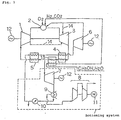
- Fig. 1 is a diagrammatic view of a turbine plant of a first embodiment according to the present invention, wherein a turbine plant using a methanol fuel is shown.
- the turbine plant using the methanol fuel of the present embodiment comprises a reformer 13 in addition to the system in the prior art shown in Fig. 9 and the methanol fuel is supplied into the combustor 2 via the reformer 13.
- a mixture of the methanol (CH 3 OH) as fuel and water (H 2 O) can be reformed into hydrogen (H 2 ) and carbon dioxide (CO 2 ) by heat of absorption Q at the reformer 13, wherein the following reaction formula takes place in the reformer 13; CH 3 OH + H 2 O + Q ⁇ H 2 + CO 2
- the heat of absorption Q is given by heat exchange at the reformer 13.
- a mixture gas of the hydrogen (H 2 ) and carbon dioxide generated by the reforming reacts on oxygen which is necessary for an equivalent combustion of the hydrogen to become a high temperature mixture gas of steam (H 2 O) and carbon dioxide (CO 2 ).
- This reaction is as follows, wherein working fluid is same as that of the prior art shown in Fig. 9. H 2 + CO 2 + 1/2 O 2 ⁇ H 2 O + CO 2
- cooling medium 14 mixed gas of steam and carbon dioxide
- construction of other portions is same as that of the prior art shown in Fig. 9.
- the reformer 13 can reform the mixture of methanol (CH 3 OH) as fuel and water (H 2 O) into hydrogen (H 2 ) and carbon dioxide (CO 2 ) by the heat of absorption O there.
- the heat of absorption Q at the reformer 13 has same effect as the fuel heating system in which fuel is heated so that fuel flow rate thereof is reduced and the gross thermal efficiency is thereby enhanced in a gas turbine using ordinary natural gas as fuel, hence the effect to enhance the gross thermal efficiency can be obtained.
- the cooling medium 14 (mixture gas of steam and carbon dioxide) is extracted from the outlet of the high pressure turbine 6 and the outlet of the compressor 1, thereby the effect to cool the high temperature portion of the high temperature turbine 3 and to enhance the reliability of the high temperature turbine 3 can be obtained.
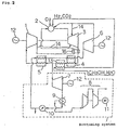
- Fig. 2 is a diagrammatic view of a turbine plant of a second embodiment according to the present invention.
- a regenerative heat exchanger 16 is provided on a downstream side of the high temperature turbine 3 so that a compressor 1 outlet gas is heat-exchanged with a high temperature turbine 3 exhaust gas, thereby a combustor 2 inlet gas temperature is elevated, fuel flow rate is reduced and the gross thermal efficiency is enhanced. Construction of other portion is same as that shown in Fig. 1 with description thereon being omitted.
- the combustor 2 inlet gas temperature is elevated more than in the first embodiment of Fig. 1, the fuel flow rate is reduced further and the effect to enhance the gross thermal efficiency further can be obtained.
- Other effect of the second embodiment is same as that of the first embodiment.
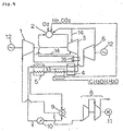
- Fig. 3 is a diagrammatic view of a turbine plant of a third embodiment according to the present invention.
- the low pressure turbine 7 and CO 2 compressor 8 with motor 11 of the bottoming system are eliminated so that construction cost thereof is reduced.
- a supply system to the condenser 9 is modified so that supply therefor is done from a heat exchanger 5 outlet.
- a supply line to the compressor 1 is modified so that supply therefor is done from a condenser 9 outlet. Construction of other portions is same as that of the second embodiment shown in Fig. 2.
- the low pressure turbine 7 and the CO 2 compressor 8 with motor 11 of the bottoming system in the second embodiment are eliminated, thereby the effect to reduce the construction cost can be obtained. Also, the effect to reduce the compressor 1 inlet gas temperature, to reduce the power of the compressor 1 and to enhance the gross thermal efficiency can be obtained.
- Other effect of the third embodiment is same as that of the second embodiment shown in Fig. 2.
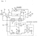
- Fig. 4 is a diagrammatic view of a turbine plant of a fairth embodiment according to the present invention.
- outlet pressure of the high temperature turbine 3 is reduced and outlet temperature of the high temperature turbine 3 is also reduced, thereby anti-creep life of a final stage moving blade of the high temperature turbine 3 is elongated.
- the low pressure turbine 7 is eliminated, thereby construction cost thereof is reduced.
- a supply system to the condenser 9 is modified so that supply therefor is done from a heat exchanger 5 outlet.
- a supply line to the compressor 1 is modified so that supply therefor is done from a condenser 9 outlet. Construction of other portions is same as that of the second embodiment shown in Fig. 2.
- the effect to elongate the anti-creep life of the final stage moving blade of the high temperature turbine 3 can be obtained.
- the low pressure turbine 7 being eliminated, the effect to reduce the construction cost can be obtained.
- the effect to reduce the compressor 1 inlet gas temperature, to reduce the power of the compressor 1 and to enhance the gross thermal efficiency can be obtained.
- Other effect of the fourth embodiment is same as that of the second embodiment.
- Fig. 5 is a diagrammatic view of a turbine plant of a fifth embodiment according to the present invention.
- an intercooler 15 is added to the prior art example shown in Fig. 9. That is, the compressor 1 of the prior art example shown in Fig. 9 is divided into a low pressure compressor 1a and a high pressure compressor 1b and further an intercooler 15 is provided therebetween.
- a low pressure compressor 1a outlet gas (a high pressure compressor 1b inlet gas) is mixed with the pressurized water which has been pressurized approximately to a low pressure compressor 1a outlet pressure by the pressure pump 10 to be temperature-reduced so that a compression power of the high pressure compressor 1b is reduced and a gross thermal efficiency is enhanced.
- a high pressure compressor 1b outlet temperature is reduced, thereby reliability of a disc strength of a high pressure compressor 1b outlet portion is enhanced and further, a combustor 2 inlet gas temperature being reduced, reliability of the high temperature portion of the combustor 2 can be enhanced.
- methanol reacts on the oxygen (O 2 ) which is needed for an equivalent combustion to generate a high temperature mixture gas of steam (H 2 O) and carbon dioxide (CO 2 ) by the following reaction formula: CH 3 OH + O 2 ⁇ CO 2 + 2H 2 O + heat
- the working fluid in this plant is carbon dioxide (CO 2 ) and steam (H 2 O), like in the prior art case shown in Fig. 9
- cooling medium 14 (mixture gas of steam and carbon dioxide) is extracted from an outlet of the high pressure turbine 6 and an outlet of the compressor 1.
- the effect to reduce the low pressure compressor la outlet gas temperature, to reduce the compression power of the high pressure compressor 1b and to enhance the gross thermal efficiency can be obtained. Also, the effect to reduce the high pressure compressor 1b outlet temperature and to enhance the reliability of the disc strength of the high pressure compressor 1b outlet portion can be obtained.
- the combustor 2 inlet gas temperature being reduced, the effect to enhance the reliability of the high temperature portion of the combustor 2 can be obtained.
- the cooling medium 14 mixture gas of steam and carbon dioxide
- the effect to cool the high temperature portion of the high temperature turbine 3 and to enhance the reliability of the high temperature turbine 3 can be obtained.
- Fig. 6 is a diagrammatic view of a turbine plant of a sixth embodiment according to the present invention.
- a regenerative heat exchanger 16 is provided on a downstream side of the high temperature turbine 3 so that a compressor 1 outlet gas is heat-exchanged with a high temperature turbine 3 exhaust gas, thereby a combustor 2 inlet gas temperature is elevated, fuel flow rate is reduced and the gross thermal efficiency is enhanced.
- cooling medium 14 (mixture gas of steam and carbon dioxide) is extracted from an outlet of the high pressure turbine 6 and an outlet of the compressor 1. Construction of other portions is same as that of the prior art example shown in Fig . 9.
- the combustor 2 inlet gas temperature being elevated and the fuel flow rate being reduced, the effect to enhance the gross thermal efficiency can be obtained.
- the cooling medium mixture gas of steam and carbon dioxide
- the effect to cool the high temperature portion of the high temperature turbine 3 and to enhance the reliability of the high temperature turbine 3 can be obtained.
- Fig. 7 is a diagrammatic view of a turbine plant of a seventh embodiment according to the present invention.
- the low pressure turbine 7 and CO 2 compressor 8 with motor 11 of the bottoming system are eliminated so that construction cost thereof is reduced.
- a supply system to the condenser 9 is modified so that supply therefor is done from a heat exchanger 5 outlet.
- a supply line to the compressor 1 is modified so that supply therefor is done from a condenser 9 outlet.
- the bottoming system is eliminated, thereby the effect to reduce the construction cost can be obtained. Also, the effect to reduce the compressor 1 inlet temperature, to reduce the power of the compressor 1 and to enhance the gross thermal efficiency can be obtained.
- Other effect of the seventh embodiment is same as that of the sixth embodiment shown in Fig. 6.
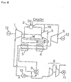
- Fig. 8 is a diagrammatic view of a turbine plant of a eighth embodiment according to the present invention.
- outlet pressure of the high temperature turbine 3 is reduced and outlet temperature of the high temperature turbine 3 is also reduced, thereby anti-creep life of a final stage moving blade of the high temperature turbine 3 is elongated.
- the low pressure turbine 7 is eliminated, thereby construction cost thereof is reduced.
- a supply system to the condenser 9 is modified so that supply therefor is done from a heat exchanger 5 outlet.
- a supply line to the compressor 1 is modified so that supply therefor is done from a condenser 9 outlet. Construction of other portions is same as that of the sixth embodiment shown in Fig. 6.
- the effect to elongate the anti-creep life of the final stage moving blade of the high temperature turbine 3 can be obtained. Also, the low pressure turbine 7 being eliminated, the effect to reduce the construction cost can be obtained. Further, the effect to reduce the compressor 1 inlet gas temperature, to reduce the power of the compressor 1 and to enhance the gross thermal efficiency can be obtained.
Landscapes
- Engineering & Computer Science (AREA)
- Chemical & Material Sciences (AREA)
- Combustion & Propulsion (AREA)
- Mechanical Engineering (AREA)
- General Engineering & Computer Science (AREA)
- Organic Chemistry (AREA)
- Health & Medical Sciences (AREA)
- Chemical Kinetics & Catalysis (AREA)
- General Health & Medical Sciences (AREA)
- Inorganic Chemistry (AREA)
- Engine Equipment That Uses Special Cycles (AREA)
Description
- The present invention relates to a turbine plant using fossil fuel including methanol and the like.
- Fig. 9 is a diagrammatic view of a prior art combined cycle power plant, using pure oxygen as oxidizing agent and methane as fuel, which has been disclosed from the Graz Institute of Technology. In the figure,
numeral 1 designates a compressor, which compresses a mixture gas of steam and carbon dioxide as working fluid to a pressure decided by an entire system optimization study.Numeral 2 designates a combustor, which is supplied, with oxygen needed for an equivalent combustion of the methane as fuel to generate a high temperature high pressure combustion gas, wherein component of the combustion gas is carbon dioxide and steam. Numeral 3 designates a high temperature turbine, which expands the high temperature high pressure combustion gas to obtain a work.Numerals high temperature turbine 3 extracted at a midpoint between theheat exchangers heat exchangers heat exchangers combustor 2 to obtain a work as well as to send the steam so expanded to be mixed into an inlet of thecombustor 2. Remaining exhaust steam of thehigh temperature turbine 3 which has passed through theheat exchangers compressor 1. - Numeral 7 designates a low pressure turbine, which expands the combustion gas extracted at the midpoint between the
heat exchangers combustor 2 approximately to the atmospheric pressure to thereby discharge the carbon dioxide as a combustion-generated product outside of the system. Numeral 9 designates a condenser, in which an outlet gas of thelow pressure turbine 7 which has been pressure-reduced by the carbon dioxide compressor (vacuum pump) 8 is heat-exchanged by the sea water or the like to be temperature-reduced so that the steam is liquefied. The liquefied water is pressurized by apressure pump 10 to -be fed into theheat exchangers low pressure turbine 7 is mostly liquefied to water at the condenser 9 and remaining portion thereof becomes a drain in the process of being compressed by thevacuum pump 8 approximately to the atmospheric pressure to be discharged outside of the system. - In the prior art combined cycle power plant as mentioned above, while the high temperature combustion gas having the component of carbon dioxide and steam is obtained using the methane as fuel and oxygen, it is also possible to use a methanol (CH3OH) fuel or other fossil fuels, but in this case, it has been a problem that the gross thermal efficiency is low.
- Such a plant is described in document WO97/44574.
- JP 04191418 A discloses a turbine plant with a compressor, a combustor and a gas turbine. The combustor is supplied with pure O2 produced by an oxygen producing device and compressed by a separate compressor and by CO2 and burning fuel. Exhaust gas of the gas turbine is thermally utilized for steam production in a heat-recovery boiler, cooled by an exhaust gas condenser and circulated to the compressor as suction gas.
- US-A-5 175 995 discloses another power generation plant where the fuel supplied to the combustor is burned therein in the presence of oxygen instead of air, too. A turbine exhaust gas is fed into a waste heat boiler to carry out heat exchanging operation therein and an exhaust gas mainly including Water components and carbon dioxide from the waste heat boiler is fed into a condenser. The gas component mainly including the carbon dioxide is separated from the condensate in the water-gas separator and recovered without emitting the same into the atmosphere. The separated gas component mainly including the carbon dioxide is fed into the combustor in a compressed state. The separated condensate is fed into the waste heat boiler to be subjected to heat exchanging operation therein to generate a super heated steam which is to be fed into the combustor.
- In view of the problem in the prior art, therefore, it is an object of the present invention to improve the prior art combined cycle power plant using the methane fuel so that a turbine plant using methanol fuel or other fossil fuels is obtained, gross thermal efficiency thereof is more enhanced than that of the prior art combined cycle power plant and reliability of the turbine plant is also enhanced.
- In order to attain said object, the present invention provides the turbine plant defined in
claim - Preferred embodiments are defined in the dependent claims.
- In the invention of
claim 1, the reformer reform the mixture of methanol (CH3OH) and water (H2O) into hydrogen (H2) and carbon dioxide (CO2), thereby the gross thermal efficiency is enhanced. Further, the high temperature portion of the high temperature turbine can be cooled by the high temperature turbine cooling system, thereby reliability of the high temperature turbine is enhanced. - In a preferred embodiment of the invention, there is provided the regenerative heat exchanger, thereby the combustor inlet gas temperature is elevated, the fuel flow rate is reduced and the-gross thermal efficiency is enhanced.
- In another embodiment of the invention, the low pressure turbine and the CO2 compressor of the bottoming system are eliminated, whereby the construction cost can be reduced more. Further, the compressor inlet temperature is reduced and the power of the compressor is reduced, thereby the gross thermal efficiency is enhanced.
- In another embodiment said bottoming system comprises a water condensing system and a CO2 compressor having no low pressure turbine therein and is constructed such that the condensed water from said bottoming system is partly led into the inlet of said compressor as the working fluid; and the exhaust gas from said high temperature turbine after so heat-exchanged at said heat exchanger is led into a condenser of said bottoming system.
- Thereby, the high temperature turbine outlet pressure is reduced and the high temperature turbine outlet temperature is reduced, thereby the anti-creep life of the final stage moving blade of the high temperature turbine can be elongated. Also, the low pressure turbine is eliminated, thereby the construction cost is reduced. Further, the compressor inlet temperature is reduced and the power of the compressor is reduced, thereby the gross thermal efficiency is enhanced.
- In the invention of
claim 2 the compressor comprises a low pressure compressor and a high pressure compressor, whereby the low pressure compressor outlet gas is temperature-reduced and the compression power is reduced, thereby the gross thermal efficiency is enhanced and reliability of the disc strength of the high pressure compressor outlet portion is enhanced. Also, the combustor inlet gas temperature is reduced, thereby reliability of the high temperature portion of the combustor is enhanced. Further, by the high temperature turbine cooling system, reliability of the high temperature turbine is also enhanced. Also, not only the methanol fuel but also other fossil fuels can be used and the surplus gas generated at an iron making plant etc. or the coal gasified fuel will be effective. - In the invention of
claim 3, the combustor inlet gas temperature is elevated by the regenerative hat exchanger and the fuel flow rate is reduced, thereby the gross thermal efficiency is enhanced. Also, the high temperature portion of the high temperature turbine is cooled by the high temperature turbine cooling system, thereby reliability of the high temperature turbine is enhanced. Also, not only the methanol fuel but also other fossil fuels can be used and the surplus gas generated at an iron making plant etc. or the coal gasified gas will be effective. - As a summary of the effects, as compared with the prior art turbine plant, herebelow mentioned remarkable effects can be obtained;
enhancement of the gross thermal efficiency,
enhancement of the reliability of the high temperature turbine by cooling of the high temperature turbine,
enhancement of the reliability of the combustor high temperature portion by reduction of the combustor inlet gas temperature,
enhancement of the disc strength of the high pressure compressor outlet portion,
reduction of the construction cost by elimination of the low pressure turbine and/or the high pressure turbine, etc. - Also, the present invention is effective not only for the methanol fuel but also for other fossil fuels including the surplus gas generated at an iron making plant and the coal gasified fuel.
-
- Fig. 1 is a diagrammatic view of a turbine plant of a first embodiment according to the present invention.
- Fig. 2 is a diagrammatic view of a turbine plant of a second embodiment according to the present invention.
- Fig. 3 is a diagrammatic view of a turbine plant of a third embodiment according to the present invention.
- Fig. 4 is a diagrammatic view of a turbine plant of a fourth embodiment according to the present invention.
- Fig. 5 is a diagrammatic view of a turbine plant of a fifth embodiment according to the present invention.
- Fig. 6 is a diagrammatic view of a turbine plant of a sixth embodiment according to the present invention.
- Fig. 7 is a diagrammatic view of a turbine plant of a seventh embodiment according to the present invention.
- Fig. 8 is a diagrammatic view of a turbine plant of a eighth embodiment according to the present invention.
- Fig. 9 is a diagrammatic view of a turbine plant in the prior art.
- Herebelow, embodiments according to the present invention will be described concretely with reference to figures. Fig. 1 is a diagrammatic view of a turbine plant of a first embodiment according to the present invention, wherein a turbine plant using a methanol fuel is shown. The turbine plant using the methanol fuel of the present embodiment comprises a
reformer 13 in addition to the system in the prior art shown in Fig. 9 and the methanol fuel is supplied into thecombustor 2 via thereformer 13. - In the
reformer 13, a mixture of the methanol (CH3OH) as fuel and water (H2O) can be reformed into hydrogen (H2) and carbon dioxide (CO2) by heat of absorption Q at thereformer 13, wherein the following reaction formula takes place in thereformer 13;
CH3OH + H2O + Q → H2 + CO2
- In said reaction formula, the heat of absorption Q is given by heat exchange at the
reformer 13. Thereby, a same effect is obtained as that of a fuel heating system in which fuel is heated so that fuel flow rate thereof is reduced and gross thermal efficiency thereof is enhanced in a gas turbine using an ordinary natural gas as fuel. Hence, by said reforming, the gross thermal efficiency can be enhanced. - Also, in the
combustor 2, a mixture gas of the hydrogen (H2) and carbon dioxide generated by the reforming reacts on oxygen which is necessary for an equivalent combustion of the hydrogen to become a high temperature mixture gas of steam (H2O) and carbon dioxide (CO2). This reaction is as follows, wherein working fluid is same as that of the prior art shown in Fig. 9.
H2 + CO2 + 1/2 O2 → H2O + CO2
- Further, in order to cool a high temperature portion of the
high temperature turbine 3, cooling medium 14 (mixture gas of steam and carbon dioxide) for thehigh temperature turbine 3 is used being extracted from an outlet of thehigh pressure turbine 6 and from an outlet of thecompressor 1. Construction of other portions is same as that of the prior art shown in Fig. 9. - According to the present first embodiment, the
reformer 13 can reform the mixture of methanol (CH3OH) as fuel and water (H2O) into hydrogen (H2) and carbon dioxide (CO2) by the heat of absorption O there. The heat of absorption Q at thereformer 13 has same effect as the fuel heating system in which fuel is heated so that fuel flow rate thereof is reduced and the gross thermal efficiency is thereby enhanced in a gas turbine using ordinary natural gas as fuel, hence the effect to enhance the gross thermal efficiency can be obtained. - Also, the cooling medium 14 (mixture gas of steam and carbon dioxide) is extracted from the outlet of the
high pressure turbine 6 and the outlet of thecompressor 1, thereby the effect to cool the high temperature portion of thehigh temperature turbine 3 and to enhance the reliability of thehigh temperature turbine 3 can be obtained. - Fig. 2 is a diagrammatic view of a turbine plant of a second embodiment according to the present invention. In the present embodiment, as compared with the first embodiment shown in Fig. 1, a
regenerative heat exchanger 16 is provided on a downstream side of thehigh temperature turbine 3 so that acompressor 1 outlet gas is heat-exchanged with ahigh temperature turbine 3 exhaust gas, thereby acombustor 2 inlet gas temperature is elevated, fuel flow rate is reduced and the gross thermal efficiency is enhanced. Construction of other portion is same as that shown in Fig. 1 with description thereon being omitted. - According to the present embodiment, by the
regenerative heat exchanger 16 being provided, thecombustor 2 inlet gas temperature is elevated more than in the first embodiment of Fig. 1, the fuel flow rate is reduced further and the effect to enhance the gross thermal efficiency further can be obtained. Other effect of the second embodiment is same as that of the first embodiment. - Fig. 3 is a diagrammatic view of a turbine plant of a third embodiment according to the present invention. In the present embodiment, as compared with the second embodiment shown in Fig. 2, the
low pressure turbine 7 and CO2 compressor 8 withmotor 11 of the bottoming system are eliminated so that construction cost thereof is reduced. Thereby, a supply system to the condenser 9 is modified so that supply therefor is done from aheat exchanger 5 outlet. Thus, a supply line to thecompressor 1 is modified so that supply therefor is done from a condenser 9 outlet. Construction of other portions is same as that of the second embodiment shown in Fig. 2. - According to the present embodiment, the
low pressure turbine 7 and the CO2 compressor 8 withmotor 11 of the bottoming system in the second embodiment are eliminated, thereby the effect to reduce the construction cost can be obtained. Also, the effect to reduce thecompressor 1 inlet gas temperature, to reduce the power of thecompressor 1 and to enhance the gross thermal efficiency can be obtained. Other effect of the third embodiment is same as that of the second embodiment shown in Fig. 2. - Fig. 4 is a diagrammatic view of a turbine plant of a fairth embodiment according to the present invention. In the present embodiment, as compared with the second embodiment shown in Fig. 2, outlet pressure of the
high temperature turbine 3 is reduced and outlet temperature of thehigh temperature turbine 3 is also reduced, thereby anti-creep life of a final stage moving blade of thehigh temperature turbine 3 is elongated. Also, thelow pressure turbine 7 is eliminated, thereby construction cost thereof is reduced. Further, a supply system to the condenser 9 is modified so that supply therefor is done from aheat exchanger 5 outlet. Thus, a supply line to thecompressor 1 is modified so that supply therefor is done from a condenser 9 outlet. Construction of other portions is same as that of the second embodiment shown in Fig. 2. - According to the present embodiment, as mentioned above, the effect to elongate the anti-creep life of the final stage moving blade of the
high temperature turbine 3 can be obtained. Also, thelow pressure turbine 7 being eliminated, the effect to reduce the construction cost can be obtained. Further, the effect to reduce thecompressor 1 inlet gas temperature, to reduce the power of thecompressor 1 and to enhance the gross thermal efficiency can be obtained. Other effect of the fourth embodiment is same as that of the second embodiment. - Fig. 5 is a diagrammatic view of a turbine plant of a fifth embodiment according to the present invention. In the present embodiment, which uses methanol as fuel, an
intercooler 15 is added to the prior art example shown in Fig. 9. That is, thecompressor 1 of the prior art example shown in Fig. 9 is divided into alow pressure compressor 1a and a high pressure compressor 1b and further anintercooler 15 is provided therebetween. In thisintercooler 15, alow pressure compressor 1a outlet gas (a high pressure compressor 1b inlet gas) is mixed with the pressurized water which has been pressurized approximately to alow pressure compressor 1a outlet pressure by thepressure pump 10 to be temperature-reduced so that a compression power of the high pressure compressor 1b is reduced and a gross thermal efficiency is enhanced. Also, a high pressure compressor 1b outlet temperature is reduced, thereby reliability of a disc strength of a high pressure compressor 1b outlet portion is enhanced and further, acombustor 2 inlet gas temperature being reduced, reliability of the high temperature portion of thecombustor 2 can be enhanced. - Also, in the
combustor 2, methanol (CH3OH) reacts on the oxygen (O2) which is needed for an equivalent combustion to generate a high temperature mixture gas of steam (H2O) and carbon dioxide (CO2) by the following reaction formula:
CH3OH + O2 → CO2 + 2H2O + heat
- Accordingly, the working fluid in this plant is carbon dioxide (CO2) and steam (H2O), like in the prior art case shown in Fig. 9
- Also, in order to cool the high temperature portion of the
high temperature turbine 3, cooling medium 14 (mixture gas of steam and carbon dioxide) is extracted from an outlet of thehigh pressure turbine 6 and an outlet of thecompressor 1. - It is to be noted that although a case to use methanol as fuel has been described here, it is also possible to use other fossil fuels. Further, it is also effective to use a fuel of a surplus gas generated at an iron making plant or the like, a coal gasified fuel, etc.
- According to the present embodiment, as mentioned above, the effect to reduce the low pressure compressor la outlet gas temperature, to reduce the compression power of the high pressure compressor 1b and to enhance the gross thermal efficiency can be obtained. Also, the effect to reduce the high pressure compressor 1b outlet temperature and to enhance the reliability of the disc strength of the high pressure compressor 1b outlet portion can be obtained.
- Further, the
combustor 2 inlet gas temperature being reduced, the effect to enhance the reliability of the high temperature portion of thecombustor 2 can be obtained. Also, the cooling medium 14 (mixture gas of steam and carbon dioxide) being extracted from thehigh pressure turbine 6 outlet and thecompressor 1 outlet, the effect to cool the high temperature portion of thehigh temperature turbine 3 and to enhance the reliability of thehigh temperature turbine 3 can be obtained. - Fig. 6 is a diagrammatic view of a turbine plant of a sixth embodiment according to the present invention. In the present embodiment, a
regenerative heat exchanger 16 is provided on a downstream side of thehigh temperature turbine 3 so that acompressor 1 outlet gas is heat-exchanged with ahigh temperature turbine 3 exhaust gas, thereby acombustor 2 inlet gas temperature is elevated, fuel flow rate is reduced and the gross thermal efficiency is enhanced. - Also, in order to cool the high temperature portion of the
high temperature turbine 3, like in the fifth embodiment, cooling medium 14 (mixture gas of steam and carbon dioxide) is extracted from an outlet of thehigh pressure turbine 6 and an outlet of thecompressor 1. Construction of other portions is same as that of the prior art example shown in Fig . 9. - According to the present embodiment, the
combustor 2 inlet gas temperature being elevated and the fuel flow rate being reduced, the effect to enhance the gross thermal efficiency can be obtained. Also, the cooling medium (mixture gas of steam and carbon dioxide) being extracted from thehigh pressure turbine 6 and thecompressor 1 outlet, the effect to cool the high temperature portion of thehigh temperature turbine 3 and to enhance the reliability of thehigh temperature turbine 3 can be obtained. - Fig. 7 is a diagrammatic view of a turbine plant of a seventh embodiment according to the present invention. In the present embodiment, as compared with the sixth embodiment shown in Fig. 6, the
low pressure turbine 7 and CO2 compressor 8 withmotor 11 of the bottoming system are eliminated so that construction cost thereof is reduced. Also, a supply system to the condenser 9 is modified so that supply therefor is done from aheat exchanger 5 outlet. Thus, a supply line to thecompressor 1 is modified so that supply therefor is done from a condenser 9 outlet. - According to the present embodiment, the bottoming system is eliminated, thereby the effect to reduce the construction cost can be obtained. Also, the effect to reduce the
compressor 1 inlet temperature, to reduce the power of thecompressor 1 and to enhance the gross thermal efficiency can be obtained. Other effect of the seventh embodiment is same as that of the sixth embodiment shown in Fig. 6. - Fig. 8 is a diagrammatic view of a turbine plant of a eighth embodiment according to the present invention. In the present embodiment, as compared with the sixth embodiment shown in Fig. 6, outlet pressure of the
high temperature turbine 3 is reduced and outlet temperature of thehigh temperature turbine 3 is also reduced, thereby anti-creep life of a final stage moving blade of thehigh temperature turbine 3 is elongated. Also, thelow pressure turbine 7 is eliminated, thereby construction cost thereof is reduced. Further, a supply system to the condenser 9 is modified so that supply therefor is done from aheat exchanger 5 outlet. Thus, a supply line to thecompressor 1 is modified so that supply therefor is done from a condenser 9 outlet. Construction of other portions is same as that of the sixth embodiment shown in Fig. 6. - According to the present embodiment, as mentioned above, the effect to elongate the anti-creep life of the final stage moving blade of the
high temperature turbine 3 can be obtained. Also, thelow pressure turbine 7 being eliminated, the effect to reduce the construction cost can be obtained. Further, the effect to reduce thecompressor 1 inlet gas temperature, to reduce the power of thecompressor 1 and to enhance the gross thermal efficiency can be obtained.
Claims (7)
- A turbine plant comprising
a compressor (1) for compressing a mixture gas of steam and carbon dioxide as a working fluid;
a combustor (2) for burning a fuel together with the working fluid from said compressor (1) added with oxygen;
a high temperature turbine (3) for expanding a combustion gas from said combustor (2) to obtain a work;
a bottoming system comprising a water condensing system;
a heat exchanger (4,5) for heating a condensed water from said bottoming system to a high temperature steam by a heat exchange with the exhaust gas from said high temperature turbine (3) and for leading said exhaust gas after used for the heat exchange into an inlet of said compressor (1) as the working fluid; and
a high pressure turbine (6) for expanding the high temperature steam of said bottoming system heated at said heat exchanger (4,5) to obtain a work and for mixing the steam so expanded into said combustor (2);
characterized in further comprising
a reformer (13) for receiving a mixture of methanol and water to be reformed into hydrogen and carbon dioxide by heat absorbed at said heat exchanger (4) and for supplying said hydrogen and carbon dioxide into said combustor (2) as a fuel; and
a high temperature turbine cooling system which extracts the working fluid from an outlet of said compressor (1) and an outlet of said high pressure turbine (6) to be led into a high temperature portion of said high temperature turbine (3) for cooling thereof as a cooling medium. - A turbine plant comprising
a compressor (1) for compressing a mixture gas of steam and carbon dioxide as a working fluid;
a combustor (2) for burning a fossil fuel including methanol together with the working fluid from said compressor (1) added with oxygen;
a high temperature turbine (3) for expanding a combustion gas from said combustor (2) to obtain a work;
a bottoming system for driving a low pressure turbine (7) by an exhaust gas from said high temperature turbine (3) to obtain work;
a heat exchanger (4,5) for heating a condensed water from said bottoming system to a high temperature steam by a heat exchange with the exhaust gas from said high temperature turbine (3) and for leading said exhaust gas after used for the heat exchange into an inlet of said compressor (1) as the working fluid; and
a high pressure turbine (6) for expanding the high temperature steam of said bottoming system heated at said heat exchanger (4,5) to obtain a work and for mixing the steam so expanded into said combustor (2);
characterized in that
said compressor (1) comprises a low pressure compressor (1a) and a high pressure compressor (1b) and is constructed such that there is provided between said low pressure compressor (1a) and said high pressure compressor (1b) a passage for flowing therethrough the working fluid via an intercooler (15); and
a portion of the condensed water from said bottoming system is mixed into said intercooler (15) under pressure;
and there is provided a high temperature turbine cooling system which extracts the working fluid from an outlet of said high pressure compressor (1b) and an outlet of said high pressure turbine (6) to be led into a high temperature portion of said high temperature turbine (3) for cooling thereof as a cooling medium. - A turbine plant comprising
a compressor (1) for compressing a mixture gas of steam and carbon dioxide as a working fluid;
a combustor (2) for burning a fossil fuel including methanol together with the working fluid from said compressor (1) added with oxygen;
a high temperature turbine (3) for expanding a combustion gas from said combustor (2) to obtain a work;
a bottoming system comprising a water condensing system;
a heat exchanger (4,5) for heating a condensed water from said bottoming system to a high temperature steam by a heat exchange with the exhaust gas from said high temperature turbine (3) and for leading said exhaust gas after used for the heat exchange into an inlet of said compressor (1) as the working fluid; and
a high pressure turbine (6) for expanding the high temperature steam of said bottoming system heated at said heat exchanger (4,5) to obtain a work and for mixing the steam so expanded into said combustor (2) ;
characterized in that
there is provided between the outlet of said compressor (1) and an inlet of said combustor (2) a regenerative heat exchanger (16) for elevating a combustor (2) inlet gas temperature by a heat exchange between an outlet gas of said compressor (1) and the exhaust gas from said high temperature turbine (3) ; and
there is provided a high temperature turbine cooling system which extracts the working fluid from an outlet of said compressor (1) and an outlet of said high pressure turbine (6) to be led into a high temperature portion of said high temperature turbine (3) for cooling thereof as a cooling medium. - A turbine plant as claimed in claim 1 characterized in that there is provided between the outlet of said compressor (1) and an inlet of said combustor (2) a regenerative heat exchanger (16) for elevating a combustor (2) inlet gas temperature by a heat exchange between an outlet gas of said compressor (1) and the exhaust gas from said high temperature turbine (3).
- A turbine plant as claimed in claim 1, 3 or 4,
characterized in that
said bottoming system comprises only the water condensing system and is constructed such that the condensed water from said bottoming system is partly led into the inlet of said compressor (1) as the working fluid; and
the exhaust gas from said high temperature turbine (3) after so heat-exchanged at said heat exchanger (4,5) is led into a condenser (9) of said bottoming system. - A turbine plant as claimed in claim 1, 3 or 4,
characterized in that
said bottoming system comprises the water condensing system and a CO2 compressor (8) and is constructed such that the condensed water from said bottoming system is partly led into the inlet of said compressor (1) as the working fluid; and
the exhaust gas from said high temperature turbine (3) after so heat-exchanged at said heat exchanger (4,5) is led into a condenser (9) of said bottoming system. - A turbine plant as claimed in claim 1, 3 or 4, characterized in that said bottoming system comprises a low pressure turbine (7) driven by an exhaust gas from said high temperature turbine (3) to obtain work.
Applications Claiming Priority (4)
| Application Number | Priority Date | Filing Date | Title |
|---|---|---|---|
| JP9466398A JPH11294114A (en) | 1998-04-07 | 1998-04-07 | Turbine plant |
| JP9466298A JPH11294113A (en) | 1998-04-07 | 1998-04-07 | Turbine plant |
| JP9466298 | 1998-04-07 | ||
| JP9466398 | 1998-04-07 |
Publications (3)
| Publication Number | Publication Date |
|---|---|
| EP0949405A2 EP0949405A2 (en) | 1999-10-13 |
| EP0949405A3 EP0949405A3 (en) | 2002-06-12 |
| EP0949405B1 true EP0949405B1 (en) | 2006-05-31 |
Family
ID=26435935
Family Applications (1)
| Application Number | Title | Priority Date | Filing Date |
|---|---|---|---|
| EP99106503A Expired - Lifetime EP0949405B1 (en) | 1998-04-07 | 1999-03-30 | Turbine plant |
Country Status (4)
| Country | Link |
|---|---|
| US (3) | US6260348B1 (en) |
| EP (1) | EP0949405B1 (en) |
| CA (1) | CA2267687C (en) |
| DE (1) | DE69931548T2 (en) |
Families Citing this family (64)
| Publication number | Priority date | Publication date | Assignee | Title |
|---|---|---|---|---|
| GB9817292D0 (en) * | 1998-08-07 | 1998-10-07 | Nokia Mobile Phones Ltd | Digital video coding |
| US6608395B1 (en) * | 2000-03-28 | 2003-08-19 | Kinder Morgan, Inc. | Hybrid combined cycle power generation facility |
| US6824710B2 (en) * | 2000-05-12 | 2004-11-30 | Clean Energy Systems, Inc. | Working fluid compositions for use in semi-closed brayton cycle gas turbine power systems |
| US6916564B2 (en) * | 2000-05-31 | 2005-07-12 | Nuvera Fuel Cells, Inc. | High-efficiency fuel cell power system with power generating expander |
| US6921595B2 (en) | 2000-05-31 | 2005-07-26 | Nuvera Fuel Cells, Inc. | Joint-cycle high-efficiency fuel cell system with power generating turbine |
| US6651421B2 (en) * | 2000-10-02 | 2003-11-25 | Richard R. Coleman | Coleman regenerative engine with exhaust gas water extraction |
| AU2002359575A1 (en) * | 2001-12-05 | 2003-06-23 | Lawrence G. Clawson | High efficiency otto cycle engine with power generating expander |
| ATE343048T1 (en) * | 2002-03-14 | 2006-11-15 | Alstom Technology Ltd | THERMAL POWER PROCESS |
| US6532745B1 (en) * | 2002-04-10 | 2003-03-18 | David L. Neary | Partially-open gas turbine cycle providing high thermal efficiencies and ultra-low emissions |
| US7178339B2 (en) * | 2004-04-07 | 2007-02-20 | Lockheed Martin Corporation | Closed-loop cooling system for a hydrogen/oxygen based combustor |
| WO2005100754A2 (en) | 2004-04-16 | 2005-10-27 | Clean Energy Systems, Inc. | Zero emissions closed rankine cycle power system |
| CA2575629A1 (en) * | 2004-06-11 | 2006-08-10 | Nuvera Fuel Cells, Inc. | Fuel fired hydrogen generator |
| US7096674B2 (en) * | 2004-09-15 | 2006-08-29 | General Electric Company | High thrust gas turbine engine with improved core system |
| US7093446B2 (en) * | 2004-09-15 | 2006-08-22 | General Electric Company | Gas turbine engine having improved core system |
| US20060149423A1 (en) * | 2004-11-10 | 2006-07-06 | Barnicki Scott D | Method for satisfying variable power demand |
| US20070006566A1 (en) * | 2005-07-05 | 2007-01-11 | General Electric Company | Syngas turbine |
| US7266940B2 (en) * | 2005-07-08 | 2007-09-11 | General Electric Company | Systems and methods for power generation with carbon dioxide isolation |
| US7726114B2 (en) * | 2005-12-07 | 2010-06-01 | General Electric Company | Integrated combustor-heat exchanger and systems for power generation using the same |
| US7634915B2 (en) * | 2005-12-13 | 2009-12-22 | General Electric Company | Systems and methods for power generation and hydrogen production with carbon dioxide isolation |
| EP1808588A1 (en) * | 2006-01-14 | 2007-07-18 | Thermal PowerTec GmbH | Augmentation of power output and efficiency in gas turbine and combined cycle plants |
| EP1991770A4 (en) * | 2006-02-21 | 2013-08-21 | Clean Energy Systems Inc | Hybrid oxy-fuel combustion power process |
| US20080314018A1 (en) * | 2007-06-08 | 2008-12-25 | Subhash Chander | Operation of internal combustion (IC) engines and gas turbines with concurrently generated oxygen enriched air |
| US8806849B2 (en) * | 2008-07-30 | 2014-08-19 | The University Of Wyoming | System and method of operating a power generation system with an alternative working fluid |
| US20100024378A1 (en) * | 2008-07-30 | 2010-02-04 | John Frederick Ackermann | System and method of operating a gas turbine engine with an alternative working fluid |
| US8534073B2 (en) * | 2008-10-27 | 2013-09-17 | General Electric Company | System and method for heating a fuel using an exhaust gas recirculation system |
| WO2010081656A2 (en) * | 2009-01-15 | 2010-07-22 | Martin Hadlauer | Coupled gas/steam turbine |
| CH700310A1 (en) * | 2009-01-23 | 2010-07-30 | Alstom Technology Ltd | Processes for CO2 capture from a combined cycle power plant and combined cycle power plant with a gas turbine with flow separation and recirculation. |
| US8596075B2 (en) | 2009-02-26 | 2013-12-03 | Palmer Labs, Llc | System and method for high efficiency power generation using a carbon dioxide circulating working fluid |
| BRPI1008485B1 (en) | 2009-02-26 | 2020-06-02 | Palmer Labs, Llc | APPARATUS AND METHOD FOR COMBUSTING A FUEL IN HIGH PRESSURE AND HIGH TEMPERATURE AND ASSOCIATED SYSTEM AND DEVICE. |
| US10018115B2 (en) | 2009-02-26 | 2018-07-10 | 8 Rivers Capital, Llc | System and method for high efficiency power generation using a carbon dioxide circulating working fluid |
| US8869889B2 (en) | 2010-09-21 | 2014-10-28 | Palmer Labs, Llc | Method of using carbon dioxide in recovery of formation deposits |
| US9410481B2 (en) * | 2010-09-21 | 2016-08-09 | 8 Rivers Capital, Llc | System and method for high efficiency power generation using a nitrogen gas working fluid |
| US20120067054A1 (en) | 2010-09-21 | 2012-03-22 | Palmer Labs, Llc | High efficiency power production methods, assemblies, and systems |
| CN102080600B (en) * | 2010-12-01 | 2013-07-17 | 株洲南方燃气轮机成套制造安装有限公司 | System and method for generating power by applying chemical purge gas |
| US20120159924A1 (en) * | 2010-12-23 | 2012-06-28 | General Electric Company | System and method for increasing efficiency and water recovery of a combined cycle power plant |
| TWI564474B (en) * | 2011-03-22 | 2017-01-01 | 艾克頌美孚上游研究公司 | Integrated systems for controlling stoichiometric combustion in turbine systems and methods of generating power using the same |
| JP6652694B2 (en) | 2011-08-04 | 2020-02-26 | カニンガム,スティーブン,エル. | Plasma arc furnace and applications |
| US20130036723A1 (en) * | 2011-08-08 | 2013-02-14 | Air Liquide Process And Construction Inc. | Oxy-combustion gas turbine hybrid |
| MX345755B (en) | 2011-11-02 | 2017-02-15 | 8 Rivers Capital Llc | Power generating system and corresponding method. |
| US9540999B2 (en) * | 2012-01-17 | 2017-01-10 | Peregrine Turbine Technologies, Llc | System and method for generating power using a supercritical fluid |
| EA028822B1 (en) | 2012-02-11 | 2018-01-31 | Палмер Лэбс, Ллк | Partial oxidation reaction with closed cycle quench |
| US20150000298A1 (en) * | 2013-03-15 | 2015-01-01 | Advanced Green Technologies, Llc | Fuel conditioner, combustor and gas turbine improvements |
| WO2014146861A1 (en) * | 2013-03-21 | 2014-09-25 | Siemens Aktiengesellschaft | Power generation system and method to operate |
| JP6220586B2 (en) * | 2013-07-22 | 2017-10-25 | 8 リバーズ キャピタル,エルエルシー | Gas turbine equipment |
| JP6250332B2 (en) | 2013-08-27 | 2017-12-20 | 8 リバーズ キャピタル,エルエルシー | Gas turbine equipment |
| CN106574552B (en) | 2014-02-26 | 2018-08-14 | 派瑞格恩涡轮技术有限公司 | Power generation system with partially recycled flow path and method |
| US10066275B2 (en) | 2014-05-09 | 2018-09-04 | Stephen L. Cunningham | Arc furnace smeltering system and method |
| TWI657195B (en) | 2014-07-08 | 2019-04-21 | 美商八河資本有限公司 | A method for heating a recirculating gas stream,a method of generating power and a power generating system |
| EP3183433B1 (en) | 2014-08-22 | 2019-10-09 | Peregrine Turbine Technologies, LLC | Power generation system and method for generating power |
| JP6629843B2 (en) | 2014-09-09 | 2020-01-15 | 8 リバーズ キャピタル,エルエルシー | Production of low pressure liquid carbon dioxide from power generation systems and methods |
| US11231224B2 (en) | 2014-09-09 | 2022-01-25 | 8 Rivers Capital, Llc | Production of low pressure liquid carbon dioxide from a power production system and method |
| MA40950A (en) | 2014-11-12 | 2017-09-19 | 8 Rivers Capital Llc | SUITABLE CONTROL SYSTEMS AND PROCEDURES FOR USE WITH POWER GENERATION SYSTEMS AND PROCESSES |
| US11686258B2 (en) | 2014-11-12 | 2023-06-27 | 8 Rivers Capital, Llc | Control systems and methods suitable for use with power production systems and methods |
| US10961920B2 (en) | 2018-10-02 | 2021-03-30 | 8 Rivers Capital, Llc | Control systems and methods suitable for use with power production systems and methods |
| MY188544A (en) | 2015-06-15 | 2021-12-21 | 8 Rivers Capital Llc | System and method for startup of a power production plant |
| CN105258384B (en) * | 2015-11-26 | 2017-12-19 | 中国科学院工程热物理研究所 | A kind of thermoelectric cold polygenerations systeme of integrated thermochemical process |
| US10634048B2 (en) | 2016-02-18 | 2020-04-28 | 8 Rivers Capital, Llc | System and method for power production including methanation |
| PL3420209T3 (en) | 2016-02-26 | 2024-02-05 | 8 Rivers Capital, Llc | Systems and methods for controlling a power plant |
| CN110168058B (en) | 2016-09-13 | 2022-01-25 | 八河流资产有限责任公司 | Power production system and method utilizing partial oxidation |
| JP7366005B2 (en) | 2017-08-28 | 2023-10-20 | 8 リバーズ キャピタル,エルエルシー | Low-grade thermal optimization of recuperative supercritical CO2 power cycle |
| ES2970038T3 (en) | 2018-03-02 | 2024-05-24 | 8 Rivers Capital Llc | Systems and methods for energy production using a carbon dioxide working fluid |
| DE102021122631A1 (en) * | 2021-09-01 | 2023-03-02 | Obrist Technologies Gmbh | Drive system for a vehicle |
| US11828200B2 (en) * | 2022-02-11 | 2023-11-28 | Raytheon Technologies Corporation | Hydrogen-oxygen fueled powerplant with water and heat recovery |
| CN114776411B (en) * | 2022-05-27 | 2023-05-05 | 华能国际电力股份有限公司 | Integrated heat storage coal-fired power generation system and working method |
Family Cites Families (12)
| Publication number | Priority date | Publication date | Assignee | Title |
|---|---|---|---|---|
| US5175995A (en) * | 1989-10-25 | 1993-01-05 | Pyong-Sik Pak | Power generation plant and power generation method without emission of carbon dioxide |
| US5669216A (en) * | 1990-02-01 | 1997-09-23 | Mannesmann Aktiengesellschaft | Process and device for generating mechanical energy |
| JPH04191418A (en) * | 1990-11-26 | 1992-07-09 | Mitsubishi Heavy Ind Ltd | Carbon dioxide (co2) recovering power generation plant |
| JP3454372B2 (en) | 1994-02-04 | 2003-10-06 | 石川島播磨重工業株式会社 | Combustion method and apparatus for closed cycle gas turbine |
| JP2680782B2 (en) * | 1994-05-24 | 1997-11-19 | 三菱重工業株式会社 | Coal-fired combined power plant combined with fuel reformer |
| US5782081A (en) * | 1994-05-31 | 1998-07-21 | Pyong Sik Pak | Hydrogen-oxygen burning turbine plant |
| JP3196549B2 (en) | 1995-01-09 | 2001-08-06 | 株式会社日立製作所 | Power generation system with fuel reformer |
| US5595059A (en) * | 1995-03-02 | 1997-01-21 | Westingthouse Electric Corporation | Combined cycle power plant with thermochemical recuperation and flue gas recirculation |
| JP2880938B2 (en) | 1995-11-24 | 1999-04-12 | 株式会社東芝 | Hydrogen combustion gas turbine plant |
| SE510738C2 (en) * | 1996-05-20 | 1999-06-21 | Nonox Eng Ab | Methods and apparatus for electricity generation on the basis of combustion of gaseous fuels |
| DE69729038T2 (en) * | 1996-09-20 | 2005-05-12 | Kabushiki Kaisha Toshiba, Kawasaki | Power plant with separation and recovery of carbon dioxide |
| US5809768A (en) * | 1997-04-08 | 1998-09-22 | Mitsubishi Heavy Industries, Ltd. | Hydrogen-oxygen combustion turbine plant |
-
1999
- 1999-03-30 EP EP99106503A patent/EP0949405B1/en not_active Expired - Lifetime
- 1999-03-30 DE DE69931548T patent/DE69931548T2/en not_active Expired - Lifetime
- 1999-03-31 CA CA002267687A patent/CA2267687C/en not_active Expired - Fee Related
- 1999-04-02 US US09/285,066 patent/US6260348B1/en not_active Expired - Fee Related
-
2001
- 2001-05-30 US US09/866,710 patent/US6430916B2/en not_active Expired - Lifetime
-
2002
- 2002-03-14 US US10/096,939 patent/US6536205B2/en not_active Expired - Fee Related
Also Published As
| Publication number | Publication date |
|---|---|
| US6536205B2 (en) | 2003-03-25 |
| DE69931548D1 (en) | 2006-07-06 |
| US20010023580A1 (en) | 2001-09-27 |
| US20020095931A1 (en) | 2002-07-25 |
| US6260348B1 (en) | 2001-07-17 |
| CA2267687C (en) | 2002-02-12 |
| EP0949405A3 (en) | 2002-06-12 |
| CA2267687A1 (en) | 1999-10-07 |
| DE69931548T2 (en) | 2007-05-10 |
| EP0949405A2 (en) | 1999-10-13 |
| US6430916B2 (en) | 2002-08-13 |
Similar Documents
| Publication | Publication Date | Title |
|---|---|---|
| EP0949405B1 (en) | Turbine plant | |
| EP1580483B1 (en) | Steam turbine plant | |
| US7703271B2 (en) | Cogeneration method and device using a gas turbine comprising a post-combustion chamber | |
| CN1043390C (en) | Method and apparatus for combinatively producing electric and machine energy | |
| EP0622535B1 (en) | Use of nitrogen from an air separation unit as gas turbine air compressor feed refrigerant to improve power output | |
| CN101622425B (en) | System and method for oxygen separation in an integrated gasification combined cycle system | |
| US6868677B2 (en) | Combined fuel cell and fuel combustion power generation systems | |
| US5410869A (en) | Method of operating a combination power plant by coal or oil gasification | |
| US7421835B2 (en) | Air-staged reheat power generation system | |
| US5669216A (en) | Process and device for generating mechanical energy | |
| WO2001095409A3 (en) | Joint-cycle high-efficiency fuel cell system with power generating turbine | |
| JPH1068329A (en) | Manufacture of synthesis gas and energy in combination | |
| US6338239B1 (en) | Turbine system having a reformer and method thereof | |
| US5349810A (en) | Humid air turbine (HAT) cycle power process | |
| EP1091095B1 (en) | Gas turbine system and combined plant comprising the same | |
| US20080141645A1 (en) | System and method for low emissions combustion | |
| CN101566103A (en) | Power cycle method using hydrogen as fuel | |
| WO2021121762A1 (en) | Energy conversion system | |
| JPH11294114A (en) | Turbine plant | |
| JPH11294113A (en) | Turbine plant | |
| Campanari et al. | The integration of atmospheric molten carbonate fuel cells with gas turbine and steam cycles | |
| JPH06318464A (en) | Operating method of fuel cell/gas turbine composite generating system | |
| JP2005097023A (en) | Hydrogen production system |
Legal Events
| Date | Code | Title | Description |
|---|---|---|---|
| PUAI | Public reference made under article 153(3) epc to a published international application that has entered the european phase |
Free format text: ORIGINAL CODE: 0009012 |
|
| 17P | Request for examination filed |
Effective date: 19990427 |
|
| AK | Designated contracting states |
Kind code of ref document: A2 Designated state(s): AT BE CH CY DE DK ES FI FR GB GR IE IT LI LU MC NL PT SE |
|
| AX | Request for extension of the european patent |
Free format text: AL;LT;LV;MK;RO;SI |
|
| PUAL | Search report despatched |
Free format text: ORIGINAL CODE: 0009013 |
|
| AK | Designated contracting states |
Kind code of ref document: A3 Designated state(s): AT BE CH CY DE DK ES FI FR GB GR IE IT LI LU MC NL PT SE |
|
| AX | Request for extension of the european patent |
Free format text: AL;LT;LV;MK;RO;SI |
|
| AKX | Designation fees paid |
Designated state(s): CH DE FR GB IT LI |
|
| 17Q | First examination report despatched |
Effective date: 20040415 |
|
| GRAP | Despatch of communication of intention to grant a patent |
Free format text: ORIGINAL CODE: EPIDOSNIGR1 |
|
| GRAS | Grant fee paid |
Free format text: ORIGINAL CODE: EPIDOSNIGR3 |
|
| GRAA | (expected) grant |
Free format text: ORIGINAL CODE: 0009210 |
|
| AK | Designated contracting states |
Kind code of ref document: B1 Designated state(s): CH DE FR GB IT LI |
|
| PG25 | Lapsed in a contracting state [announced via postgrant information from national office to epo] |
Ref country code: LI Free format text: LAPSE BECAUSE OF FAILURE TO SUBMIT A TRANSLATION OF THE DESCRIPTION OR TO PAY THE FEE WITHIN THE PRESCRIBED TIME-LIMIT Effective date: 20060531 Ref country code: IT Free format text: LAPSE BECAUSE OF FAILURE TO SUBMIT A TRANSLATION OF THE DESCRIPTION OR TO PAY THE FEE WITHIN THE PRESCRIBED TIME-LIMIT;WARNING: LAPSES OF ITALIAN PATENTS WITH EFFECTIVE DATE BEFORE 2007 MAY HAVE OCCURRED AT ANY TIME BEFORE 2007. THE CORRECT EFFECTIVE DATE MAY BE DIFFERENT FROM THE ONE RECORDED. Effective date: 20060531 Ref country code: CH Free format text: LAPSE BECAUSE OF FAILURE TO SUBMIT A TRANSLATION OF THE DESCRIPTION OR TO PAY THE FEE WITHIN THE PRESCRIBED TIME-LIMIT Effective date: 20060531 |
|
| REG | Reference to a national code |
Ref country code: GB Ref legal event code: FG4D Ref country code: CH Ref legal event code: EP |
|
| REF | Corresponds to: |
Ref document number: 69931548 Country of ref document: DE Date of ref document: 20060706 Kind code of ref document: P |
|
| REG | Reference to a national code |
Ref country code: CH Ref legal event code: PL |
|
| PLBE | No opposition filed within time limit |
Free format text: ORIGINAL CODE: 0009261 |
|
| STAA | Information on the status of an ep patent application or granted ep patent |
Free format text: STATUS: NO OPPOSITION FILED WITHIN TIME LIMIT |
|
| EN | Fr: translation not filed | ||
| 26N | No opposition filed |
Effective date: 20070301 |
|
| GBPC | Gb: european patent ceased through non-payment of renewal fee |
Effective date: 20070330 |
|
| PG25 | Lapsed in a contracting state [announced via postgrant information from national office to epo] |
Ref country code: GB Free format text: LAPSE BECAUSE OF NON-PAYMENT OF DUE FEES Effective date: 20070330 Ref country code: FR Free format text: LAPSE BECAUSE OF FAILURE TO SUBMIT A TRANSLATION OF THE DESCRIPTION OR TO PAY THE FEE WITHIN THE PRESCRIBED TIME-LIMIT Effective date: 20070309 |
|
| PG25 | Lapsed in a contracting state [announced via postgrant information from national office to epo] |
Ref country code: FR Free format text: LAPSE BECAUSE OF FAILURE TO SUBMIT A TRANSLATION OF THE DESCRIPTION OR TO PAY THE FEE WITHIN THE PRESCRIBED TIME-LIMIT Effective date: 20060531 |
|
| PGFP | Annual fee paid to national office [announced via postgrant information from national office to epo] |
Ref country code: DE Payment date: 20130327 Year of fee payment: 15 |
|
| REG | Reference to a national code |
Ref country code: DE Ref legal event code: R119 Ref document number: 69931548 Country of ref document: DE |
|
| REG | Reference to a national code |
Ref country code: DE Ref legal event code: R119 Ref document number: 69931548 Country of ref document: DE Effective date: 20141001 |
|
| PG25 | Lapsed in a contracting state [announced via postgrant information from national office to epo] |
Ref country code: DE Free format text: LAPSE BECAUSE OF NON-PAYMENT OF DUE FEES Effective date: 20141001 |