BACKGROUND OF THE INVENTION
1. Field of the Invention
-
The present invention relates to a low-noise level landing
apparatus and system for helicopters, which is intended to reduce
noise generated during landing approach.
-
Noise generated from a helicopter during landing approach
is mostly caused by the rotation of a main rotor. In particular,
BVI (blade vortex interaction) noise is an impulsive noise which
is caused by a sudden change of the blade air load during the
interaction between the blade and previously shed blade tip
vortex. The BVI noise, if generated, is louder than any other
noise sources.
-
Fig. 8 is a graph showing an example of a BVI noise
generating area with respect to the airspeed and descending speed
of a helicopter. In this example, it is understood that the BVI
noise is generated when the airspeed is in the range of 40 to
120 kt (knots) and the descending speed is in the range of 300
to 1,200 ft (feet) /minute, and that the BVI noise is loudest when
the descending angle is in the range of 4° to 6° .
-
For this reason, in order to minimize the BVI noise, it
is desired that a helicopter should take a curved flight route
by continuously changing the descending angle from the start of
landing in order to avoid the BVI noise generating area.
-
However, it is very difficult for the pilot to bear the
noise generating conditions shown in Fig. 8 in mind, to select
a low-noise level flight route with the aid of instruments while
manually controlling the helicopter. In particular, safety is
the top priority during landing, and noise reduction is apt to
be of secondary importance.
-
As an example of prior art, Japanese Patent No. 2,736,045
(Japanese Patent Application No. Hei 8-63558) has been disclosed,
wherein a flight route is selected on the basis of a BVI noise
generating area database obtained by previous analyses, flight
tests and the like. However, the BVI noise generating area is
subjected to the effects of meteorological conditions, in
particular, the effect of wind, whereby low-noise level landing
approach may not be accomplished in some cases.
-
Fig. 9 is a graph showing how the BVI noise generating
area is changed. A flight route P1 is selected on the basis of
the BVI noise generating area database. When meteorological
conditions are no wind and the same as those under which the BVI
noise generating area database is obtained, this route becomes
a low-noise level landing route.
-
However, if the shape and position of the BVI noise
generating area are changed by the effect of wind, the flight
route P1 enters the BVI noise generating area, and is no longer
a low-noise level route. As a matter of fact, a flight route
P2 have been modified in accordance with the change of the area
becomes a low-noise level landing route.
SUMMARY OF THE INVENTION
-
An object of the present invention is to provide a
low-noise level landing apparatus and system for helicopters,
capable of more properly selecting a flight route in which noise
during landing approach can be reduced, in response to changes
in meteorological conditions without imposing any additional
burden on the pilot.
-
The present invention provides a low-noise level landing
apparatus for helicopters, provided on a helicopter, comprising:
- data receiving means for receiving noise data measured
on a ground by data communication;
- helicopter position calculating means for calculating a
position of the helicopter;
- landing route setting means for setting a landing route;
- air data measuring means for measuring an airspeed and
a descending speed;
- rotor rotational speed measuring means for measuring a
rotor rotational speed;
- helicopter weight measuring means for measuring a weight
of the helicopter;
- noise generating area database means for storing noise
levels with respect to parameters of descending speed, airspeed,
descending angle, rotor rotational speed and helicopter weight;
and
- flight route calculating means for determining a low-noise
level flight route by setting a plurality of flight routes
on the basis of the helicopter position and landing point and
by referring to the noise generating area database with regard
to those data from each measuring means,
- wherein the flight route calculating means modifies a
preselected flight route on the basis of the noise data from the
data receiving means and reselects an optimal flight route.
-
-
According to the invention, since noise levels with
respect to parameters of descending speed, airspeed, descending
angle, rotor rotational speed and helicopter weight have been
stored, any change in noise level at a landing point in accordance
with changes in flight conditions can be followed accurately.
In addition, since the measuring means is provided for each
parameter, the noise level at the landing point during flight
can be grasped properly. The descending angle can be calculated
from the descending speed and the airspeed. The descending speed
can also be calculated as a change ratio of the position of the
helicopter with time.
-
Furthermore, the low-noise level flight route can be
selected by setting a plurality of flight routes on the basis
of the helicopter position and landing point and by referring
to the noise generating area database. Moreover, even if the
current flight conditions are different from the conditions at
the creation time of the database, the selection can be
accomplished flexibly by judging the noise measured on the ground
whether the selected flight route is optimal or not, and by
modifying the flight route automatically or manually so that the
flight route becomes the optimal flight route. Flight
conditions to be considered are, for example, meteorological
conditions such as wind direction, wind speed and amount of
rainfall, as well as helicopter conditions for each model of
helicopter such as engine characteristics, rotor characteristics
and aerodynamic characteristics. Furthermore, the flight
conditions can also include differences in local noise
regulation around the heliport.
-
It is also possible to determine maneuvering conditions
such as airspeed, descending angle and rotor rotational speed,
in response to the optimal flight route. The maneuvering
conditions thus determined may be indicated on instruments to
assist pilot manual control, or may be used for automatic flight
control by a computer or the like. In this way, noise reduction
can be attained properly while reducing a burden on the pilot.
-
Furthermore, in the invention it is preferable that the
helicopter position measuring means is composed of a
differential GPS, and the data receiving means receives the noise
data and differential GPS correction data.
-
According to the invention, by using the DGPS
(Differential Global Positioning System) as the helicopter
position measuring means, it is possible to obtain a measurement
accuracy ten times higher than that of an ordinary GPS. The DGPS
corrects natural errors by using a stationary GPS receiver, and
eliminates the errors by transmitting data for correcting the
errors to a mobile GPS receiver. Since the position of the
helicopter is required to be obtained with high accuracy to
assist pilot manual control and to accomplish automatic flight
control, the application of DGPS seems to be promising for
helicopters. When using the DGPS, a data communication
apparatus for obtaining the correction data transmitted from the
ground is required to be installed on the helicopter. In the
case of the present invention, however, the noise data measured
on the ground can be transmitted to the helicopter by using this
kind of data communication without providing any special
apparatus.
-
Furthermore, in the invention it is preferable that the
low-noise level landing apparatus comprises noise level
indicating means for indicating noise levels obtained by
discriminating noise data on the basis of a plurality of
threshold values, wherein the threshold values are variable in
accordance with an altitude of the helicopter or a distance to
the landing point.
-
According to the invention, when the pilot maneuvers the
helicopter to carry out landing, the noise data measured on the
ground is indicated at classified levels, whereby the pilot can
accurately recognize whether a proper noise level is maintained
in the current landing route or not.
-
Since the position of the helicopter is changing at this
time with respect to the position of a microphone on the ground,
the noise level to be measured becomes different in accordance
with the difference in distance between the microphone and the
helicopter even though the noise level generated by the
helicopter remains the same.
-
To solve this problem, by varying the threshold value of
noise level in which allowance is made for an effect of noise
attenuation due to distance, in accordance with the direction
and distance of the helicopter from the microphone, the accuracy
of the noise level indicated on the helicopter side can be
enhanced. As a result, it is possible to accurately grasp
whether the BVI noise is generated or not. One microphone may
be installed at one position on the ground, or a plurality of
microphones may be installed around the landing point, and the
values obtained by these microphones may be averaged.
-
Furthermore, the invention provides a low-noise level
landing system for helicopters comprising:
- noise measuring means provided on the ground for measuring
noise of a helicopter;
- data transmitting means provided on the ground for
transmitting noise data measured by the noise measuring means
to the helicopter by data communication;
- data receiving means provided on the helicopter for
receiving the noise data transmitted by the data transmitting
means;
- helicopter position measuring means provided on the
helicopter for measuring a position of the helicopter;
- landing route setting means provided on the helicopter
for setting a landing route;
- air data measuring means provided on the helicopter for
measuring an airspeed and a descending angle;
- rotor rotational speed measuring means provided on the
helicopter for measuring a rotor rotational speed;
- helicopter weight measuring means provided on the
helicopter for measuring a weight of the helicopter;
- noise generating area database means for storing noise
levels with respect to parameters of descending speed, airspeed,
descending angle, rotor rotational speed and helicopter weight;
and
- flight route calculating means for determining a low-noise
level flight route by setting a plurality of flight routes
on the basis of the helicopter position and landing point and
by referring to the noise generating area database with regard
to those data from each measuring means,
- wherein the flight route calculating means modifies a
preselected flight route, and reselects an optimal flight route.
-
-
According to the invention, since noise levels with
respect to parameters of descending speed, airspeed, descending
angle, rotor rotational speed and helicopter weight have been
stored, any change in noise level at a landing point in accordance
with changes in flight conditions can be followed accurately.
In addition, since a measuring means is provided for each
parameter, the noise level at the landing point during flight
can be grasped properly. The descending angle can be calculated
from the descending speed and airspeed. The descending speed
can also be calculated as a change ratio of the position of the
helicopter with time.
-
Furthermore, a low-noise level flight route can be
selected by setting a plurality of flight routes on the basis
of the helicopter position and landing point and by referring
to the noise generating area database means. Moreover, even if
the current flight conditions are different from the conditions
at the creation time of the database, the selection can be
accomplished flexibly by judging the noise measured on the ground
whether the selected flight route is optimal or not, and by
modifying the flight route automatically or manually so that the
flight route becomes the optimal flight route. Flight
conditions to be considered are, for example, meteorological
conditions such as wind direction, wind speed and amount of
rainfall, as well as helicopter conditions for each model of
helicopter such as engine characteristics, rotor
characteristics and aerodynamic characteristics. Furthermore,
the flight conditions can also include differences in local noise
regulation level around the heliport.
-
It is also possible to determine maneuvering conditions
such as airspeed, descending angle and rotor rotational speed,
in response to the optimal flight route. The maneuvering
conditions thus determined may be indicated on instruments to
assist pilot manual control, or may be used for automatic flight
control by a computer or the like. In this way, noise reduction
can be attained properly while reducing a burden on the pilot.
-
The noise generating area database means and the flight
route calculating means are generally provided on the helicopter.
It is also possible to have a system wherein data from each
measuring means installed on the helicopter is transmitted to
another aircraft or the ground station once, the optimal flight
route is obtained by calculation by using the noise generating
area database means and the flight route calculating means
installed therein, and the result of the calculation is
transmitted to the helicopter.
-
Furthermore, in the invention it is preferable that the
helicopter position measuring means is composed of a
differential GPS, the data transmitting means transmits the
noise data and differential GPS correction data, and the data
receiving means receives the noise data and the differential GPS
correction data.
-
According to the present invention, by using the DGPS,
it is possible to obtain a measurement accuracy ten times higher
than that of an ordinary GPS. The DGPS corrects natural errors
by using a stationary GPS receiver, and eliminates the errors
by transmitting data for correcting the errors to a mobile GPS
receiver. Since the position of the helicopter itself is
required to be obtained with high accuracy to assist pilot manual
control and to accomplish automatic flight control, the
application of DGPS seems to be promising for helicopters. When
using the DGPS, a data communication apparatus for obtaining the
correction data is required to be installed on the helicopter.
In the case of the present invention, however, the noise data
measured on the ground can be transmitted to the helicopter by
using this kind of data communication without providing any
special apparatus.
-
In the invention it is preferable that the low-noise level
landing system further comprises:
- a flight instrument provided on a helicopter for
indicating the optimal flight route to the pilot; and
- a landing guide apparatus provided near a landing point
on the ground for projecting a landing guide light beam toward
the helicopter,
- wherein a projection angle of the landing guide light beam
is controlled on the basis of the optimal flight route.
-
-
According to the invention, the pilot can easily maintain
landing control along a low-noise level route with reference to
the optimal flight route indicated on the flight instrument.
Furthermore, the pilot can easily perform low-noise level
visual-flight landing with reference to the landing guide light
beam projected from the landing guide apparatus.
BRIEF DESCRIPTION OF THE DRAWINGS
-
Other and further objects, features, and advantages of
the invention will be more explicit from the following detailed
description taken with reference to the drawings wherein:
- Fig. 1 is an overall perspective view showing a helicopter
landing condition;
- Fig. 2 is a block diagram showing an embodiment of the
present invention;
- Fig. 3 is a view illustrating a method for selecting
helicopter landing approach routes;
- Fig. 4 is a graph showing changes in BVI noise in
accordance with flight routes Ra to Rd shown in Fig. 3;
- Fig. 5A is a graph showing a time histories of BVI noise,
and Fig. 5B is a graph showing a frequency distribution of BVI
noise;
- Fig. 6 is a distribution graph showing the contents of
Table 1;
- Figs. 7A and 7B are side and plan views, respectively,
showing a method of guiding a helicopter by indicating a landing
approach route by using a projected light beam;
- Fig. 8 is a graph showing a BVI noise generating area with
respect to the airspeed and descending speed of a helicopter;
and
- Fig. 9 is a graph showing how a BVI noise generating area
is changed by the effect of wind.
-
DETAILED DESCRIPTION OF THE PREFERRED EMBODIMENTS
-
Now referring to the drawings, preferred embodiments of
the invention are described below.
-
Fig. 1 is an overall perspective view showing a helicopter
landing condition. A helicopter HC is flying toward a heliport
HP, a landing point, and is supposed to land by taking an approach
route formed of a complicated three-dimensional curve so as to
reduce noise to be as low as possible at surrounding houses Q.
-
A plurality of microphones 20 are installed at a
sufficient distance from each other around a heliport HP to
measure noise generated from the helicopter HC. Noise signals
from the microphones 20 are collected at one position, and input
to an average noise level calculator 21, whereby the noise levels
measured at all positions of the microphones 20 are monitored
centralizedly. Noise data obtained by the average noise level
calculator 21 is incorporated as one of information for data
communication by a transmitter 22, and a radio wave is
transmitted (up-linked) from an antenna 23. By receiving the
radio wave from the antenna 23, the helicopter HC can obtain the
noise data measured around the heliport.
-
On a ground side, an antenna 30 and a GPS receiver 31 for
receiving GPS radio waves from GPS satellites are installed to
generate correction data for DGPS. The DGPS correction data is
incorporated as one of information for data communication by the
transmitter 22, and transmitted together with the noise data to
the helicopter HC.
-
With this configuration of such a ground station as
described above, the helicopter HC can promptly receives the
ground noise data and the DGPS correction data.
-
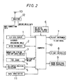
Fig. 2 is a block diagram showing an embodiment of the
present invention. In the low-noise level landing apparatus of
the helicopter, an air data sensor 1 measures an airspeed and
a descending speed, and calculates a descending angle by using
those two data. A rotor tachometer 2 measures the rotational
speed of a main rotor. Furthermore, a memory 3 for storing a
take-off gross weight having been set before starting flight,
and a fuel gauge 4 for measuring the amount of fuel consumption
are provided. On the basis of these two numerical values, the
current weight of the helicopter is calculated.
-
In addition, a helicopter position calculator 5
calculates the three-dimensional position of the helicopter and
includes a GPS (Global Positioning System) which receives radio
waves from a plurality of GPS satellites and measures the
latitude, longitude and altitude of the helicopter on the
principle of trigonometry. The helicopter position calculator
5 may be used together with a radio altimeter, a barometric
altimeter or the like to improve the measurement accuracy of the
altitude.
-
A data input device 11 comprises a keyboard, a numerical
keypad, etc., and is used by the pilot of the helicopter to enter
a variety of data. In the case of the present invention, the
data input device 11 is used to set landing point and allowable
noise levels. A BVI noise generating area database device 6 is
formed of a mass storage device such as a magnetic disk to store
BVI noise levels with respect to parameters of descending speed,
airspeed, descending angle, rotor rotational speed and
helicopter weight.
-
The level of the BVI noise changes depending on various
flight conditions. The important parameters of the flight
conditions are descending speed, airspeed, descending angle,
rotor rotational speed and weight of helicopter. A change in
the BVI noise level in accordance with changes in these various
parameters can be obtained beforehand by actual measurement and
analytical simulation. These data have been stored in the BVI
noise generation range database device 6. The results of the
actual measurement and analytical simulation have already been
detailed in Japanese Patent Application No. Hei 8-63558 applied
by the applicants of the present invention, and will not be
described here.
-
A flight instrument 7 indicates the three-dimensional
position and the flight direction of the helicopter, maps, etc.
to the pilot as the form of digital indication, analog indication,
indication on a screen and the like. A flight controller 8 is
practically utilized as an AFCS (Automatic Flight Control
System) and is used to automatically control the control system
of the helicopter so as to guide the helicopter along a flight
route which is calculated by the computer 10. A rotor rotational
speed controller 9 controls the rotational speed of a rotor by
changing RPM of the engine, or by using a continuously variable
speed change mechanism provided between the engine and a main
rotor shaft. These input and output devices are connected to
a computer 10.
-
Furthermore, an antenna 13 and a receiver 12 are installed
on the helicopter to receive radio waves transmitted from the
ground station shown in Fig. 1. Demodulated ground noise data
is transferred to the computer 10, and DGPS correction data is
received by the helicopter position calculator 5. The
helicopter position calculator 5 which has been received GPS data
by itself, corrects GPS data by using the DGPS correction data,
whereby the accuracy of the position of the helicopter itself
can be ten times improved. If a measurement accuracy of 10 meter
or less can be attained, for example, automatic landing control
by a computer becomes promising. Additionally, the ground noise
data is indicated to the pilot by the flight instrument 7 so as
to be used as a guide for low-noise level landing control.
-
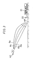
Fig. 3 is a view illustrating a method for selecting
helicopter landing approach routes. When the helicopter HC is
going to approach to the heliport HP, the computer 10 sets a
plurality of approach routes between the current helicopter
position to the landing point. The BVI noise is changed greatly
depending on various factors such as an airspeed and a descending
speed as shown in Fig. 9. Therefore, among many approach routes,
low-noise level approach routes are considerably limited in
number. As examples of approach routes, Fig. 3 shows a flight
route Ra, i. e., a straight approach route, and flight routes
Rb to Rd wherein landing gradually becomes close to vertical
landing in comparison with the flight route Ra.
-
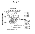
Fig. 4 is a graph showing changes in BVI noise
corresponding to the flight routes Ra to Rd shown in Fig. 3. The
axis of abscissas of the graph represents the airspeed of the
helicopter. The axis of ordinates represents the descending
speed of the helicopter, and the downward direction of the axis
of ordinates is assumed to be positive. Furthermore, areas L0
to L4 in the graph are five-step level of the BVI noise. At the
area L0, no BVI noise is generated. At the areas L1 to L4, BVI
noise is generated, and these areas are referred to as BVI noise
generating areas. The level of the BVI noise is divided into
noise levels 1 to 4. This means that the noise level becomes
highest when the helicopter passes through the area L4 having
noise level 4.
-
The flight route Ra is an approach route usually taken
by a helicopter, wherein the helicopter approaches the landing
point with the descending angle and the airspeed fixed at 6°
and about 60 kt, respectively, while decelerating simultaneously
with the starting of descending. The helicopter finally further
decelerates and then lands. In this case, the level of the BVI
noise is very high, since the helicopter is in the area L4 when
approaching the landing point.
-
When the helicopter takes the flight route Rb, the
helicopter starts approaching at a descending angle slightly
smaller than that in the case of the route Ra, the descending
angle is then gradually increased to about 7° to 8° while the
airspeed is lowered to about 50 kt, and the helicopter approaches
the landing point and then lands. In this case, the helicopter
passes through one of the BVI noise generating areas when
approaching the landing point. However, since the BVI noise
generating area is the area L1 wherein the BVI noise level is
lowest, the helicopter can land at a noise level lower than that
in the case of the route Ra.
-
When the helicopter takes the flight route Rc or Rd, the
helicopter starts approaching at a descending angle further
smaller than that in the case of the route Rb, the descending
angle is then gradually increased to about 9° to 12° while the
airspeed is lowered to about 30 to 40 kt, and the helicopter
approaches the landing point and then lands. In this case, the
helicopter can land without entering the BVI noise generating
areas.
-
For this reason, the helicopter having the noise
generating characteristics shown in Fig. 4 is desired to take
the flight route Rc or Rd from the viewpoint of noise reduction.
On the other hand, from the viewpoints of the flight
characteristics of the helicopter and the maneuver by the pilot,
the more a route is changed in such a way that the descending
angle and the airspeed are changed greatly (just as in the case
of the flight route Rd, for example), the more the route tends
to become disadvantageous. Therefore, it is necessary to make
a comprehensive judgment.
-
Fig. 5A is a graph showing a time history of the sound
pressure of the BVI noise, and Fig. 5B is a graph showing a
frequency distribution of the BVI noise. The axis of ordinates
represents the sound pressure level measured by the microphone
20 installed on the ground. The BVI noise is an impulsive noise
which is caused by a sudden change of the blade air load during
the interaction between the blade and previously shed blade tip
vortex, and large spike-like pressure changes peculiar to the
BVI noise are generated as shown in Fig. 5A. These spike-like
pressure changes cause a very loud noise which is louder than
any other kinds of noise sources.
-
When the changes in the sound pressure of the BVI noise
are subjected to the FFT (Fast Fourier Transform) process, a
frequency distribution shown in Fig. 5B is obtained, for example,
wherein the spike-like pressure changes are generated at a
specific frequency range. It is therefore possible to
quantitatively measure the BVI noise level by taking out only
the frequency range peculiar to the BVI noise by using a band-pass
filter or the like. The BVI noise level thus obtained is
discriminated with respect to a plurality of threshold values,
thereby being able to indicate at a plurality of level steps on
the flight instrument 7.
-
TABLE 1 below shows how a noise level indication
corresponding to noise data measured by the microphone on the
ground is changed depending on the distance from the microphone
to the helicopter. When it is assumed that a helicopter is
positioned 500 ft away from the microphone and another helicopter
is positioned 1,000 ft away from the microphone, and that the
measured noise levels of these helicopters are the same, that
is, 75 dB, for example, it is found that the helicopter positioned
1,000 ft away from the microphone generates a louder noise.
| Noise level measured on ground (dB) | Distance from microphone to helicopter (ft) |
| | 200 | 500 | 1000 |
| 70-80 | No BVI noise | No BVI noise | Level | 1 |
| 80-90 | No BVI noise | Level | 1 | Level 2 |
| 90-100 | Level 1 | Level 2 | Level 3 |
| 100-110 | Level 2 | Level 3 | Level 4 |
-
By checking a noise level indication on the flight
instrument 7, the pilot can understand which BVI noise generating
area the helicopter is flying. Furthermore, when the BVI noise
generating area is changed as shown in Fig. 9 because of changes
in meteorological conditions such as the direction of the wind,
the speed of the wind, the amount of rainfall, etc. the pilot
can modify the flight route to the optimal flight route on the
basis of the noise level measured on the ground.
-
In addition, a descending speed, an airspeed, a descending
angle and a rotor rotational speed corresponding to the selected
optimal flight route are determined and indicated on the flight
instrument 7. The pilot controls a helicopter so that the
control can conform to the various parameters indicated on the
flight instrument 7, thereby enabling BVI noise generating
condition to be avoided.
-
Furthermore, by supplying the selected optimal flight
route to the flight controller 8, and by shifting the control
from manual control to automatic flight control, the helicopter
is automatically guided along a flight route wherein the noise
level is lower, whereby low-noise level landing is possible
properly without depending on the ability of the pilot.
-
Moreover, it is desirable that the reference levels used
for such judgments as to be made in accordance with TABLE 1 should
be changed in accordance with an allowable local noise regulation
determined in a region wherein the helicopter is flying. For
example, in urban regions wherein noise reduction is highly
required, priority should be given to noise reduction, and
landing flight should be carried out so that a noise having level
1 or more is not generated. On the other hand, in suburban and
rural regions wherein noise does not cause any serious problems,
a noise level of up to level 2 may be allowed for example. In
this way, landing flight can be accomplished by taking a flight
route which can be selected from among many flight routes.
-
Fig. 6 is a graph in which the contents of TABLE 1 are
converted into a distribution graph and the position of the
helicopter itself is indicated. The helicopter transmits its
position to the ground station at regular time intervals. The
ground station calculates distance D from the helicopter to the
landing point, and transmits to the helicopter a reference level
corresponding to the noise level of the helicopter. As a result,
the graph shown in Fig. 6 can be obtained. By indicating this
distribution graph on the flight instrument 7 or the like, the
pilot can understand the current noise level. In addition, if
this kind of indicatory function is not provided in the
helicopter, the ground station may carry out level judgment, and
may give directions to the helicopter to change its route.
-
Figs. 7A and 7B are side and plan views, respectively,
showing a method of guiding a helicopter by indicating a landing
approach route by using a projected light beam. A landing guide
apparatus 40 is installed near the heliport HP, i. e. the landing
point, and projects a landing guide light beam BM toward the
helicopter HC. The landing guide light beam BM can form a
plurality of projection areas in accordance with changes in the
color and intensity of the light beam. For example, in a
projection area Ea, a flashing red light is distributed in the
range of 5° in the vertical direction. In a projection area Eb,
a regular red light is distributed in the range of 0.25° in the
vertical direction. In a projection area Ec, a regular green
light is distributed in the range of 0.75° in the vertical
direction. Furthermore, in a projection area Ed, a flashing
green light is distributed in the range of 2.5° in the vertical
direction. In addition, the horizontal spreading angle of the
landing guide light beam BM is set at about 12° to the right and
left sides from the axis of the projected light beam.
-
The light source of the landing guide apparatus 40 is
supported rotatably in the vertical and horizontal directions,
and the vertical and horizontal projection angles thereof are
controlled by a projection angle controller 41.
-
As shown in Fig. 1, the ground station measures the noise
generated from the helicopter HC by using the microphones 20,
monitors the noise level by using the average noise level
calculator 21, and selects the optimal flight route wherein the
noise level is allowable. The landing guide apparatus 40
controls the projection angle of the landing guide light beam
BM on the basis of the optimal flight route to guide the helicopter
HC to the landing route. As a result, the pilot can properly
carry out low-noise level visual-flight landing with reference
to the landing guide light beam BM.
-
The invention may be embodied in other specific forms
without departing from the spirit or essential characteristics
thereof. The present embodiments are therefore to be considered
in all respects as illustrative and not restrictive, the scope
of the invention being indicated by the appended claims rather
than by the foregoing description and all changes which come
within the meaning and the range of equivalency of the claims
are therefore intended to be embraced therein.