EP0944524B1 - Manufacture of an endless plastic pipe - Google Patents
Manufacture of an endless plastic pipe Download PDFInfo
- Publication number
- EP0944524B1 EP0944524B1 EP97952718A EP97952718A EP0944524B1 EP 0944524 B1 EP0944524 B1 EP 0944524B1 EP 97952718 A EP97952718 A EP 97952718A EP 97952718 A EP97952718 A EP 97952718A EP 0944524 B1 EP0944524 B1 EP 0944524B1
- Authority
- EP
- European Patent Office
- Prior art keywords
- plastic film
- wound
- hose
- winding
- adhesive
- Prior art date
- Legal status (The legal status is an assumption and is not a legal conclusion. Google has not performed a legal analysis and makes no representation as to the accuracy of the status listed.)
- Expired - Lifetime
Links
Images


Classifications
-
- B—PERFORMING OPERATIONS; TRANSPORTING
- B31—MAKING ARTICLES OF PAPER, CARDBOARD OR MATERIAL WORKED IN A MANNER ANALOGOUS TO PAPER; WORKING PAPER, CARDBOARD OR MATERIAL WORKED IN A MANNER ANALOGOUS TO PAPER
- B31C—MAKING WOUND ARTICLES, e.g. WOUND TUBES, OF PAPER, CARDBOARD OR MATERIAL WORKED IN A MANNER ANALOGOUS TO PAPER
- B31C3/00—Making tubes or pipes by feeding obliquely to the winding mandrel centre line
-
- A—HUMAN NECESSITIES
- A01—AGRICULTURE; FORESTRY; ANIMAL HUSBANDRY; HUNTING; TRAPPING; FISHING
- A01F—PROCESSING OF HARVESTED PRODUCE; HAY OR STRAW PRESSES; DEVICES FOR STORING AGRICULTURAL OR HORTICULTURAL PRODUCE
- A01F15/00—Baling presses for straw, hay or the like
- A01F15/07—Rotobalers, i.e. machines for forming cylindrical bales by winding and pressing
- A01F15/071—Wrapping devices
-
- A—HUMAN NECESSITIES
- A01—AGRICULTURE; FORESTRY; ANIMAL HUSBANDRY; HUNTING; TRAPPING; FISHING
- A01F—PROCESSING OF HARVESTED PRODUCE; HAY OR STRAW PRESSES; DEVICES FOR STORING AGRICULTURAL OR HORTICULTURAL PRODUCE
- A01F25/00—Storing agricultural or horticultural produce; Hanging-up harvested fruit
- A01F25/14—Containers specially adapted for storing
-
- B—PERFORMING OPERATIONS; TRANSPORTING
- B29—WORKING OF PLASTICS; WORKING OF SUBSTANCES IN A PLASTIC STATE IN GENERAL
- B29C—SHAPING OR JOINING OF PLASTICS; SHAPING OF MATERIAL IN A PLASTIC STATE, NOT OTHERWISE PROVIDED FOR; AFTER-TREATMENT OF THE SHAPED PRODUCTS, e.g. REPAIRING
- B29C53/00—Shaping by bending, folding, twisting, straightening or flattening; Apparatus therefor
- B29C53/56—Winding and joining, e.g. winding spirally
- B29C53/58—Winding and joining, e.g. winding spirally helically
-
- B—PERFORMING OPERATIONS; TRANSPORTING
- B29—WORKING OF PLASTICS; WORKING OF SUBSTANCES IN A PLASTIC STATE IN GENERAL
- B29C—SHAPING OR JOINING OF PLASTICS; SHAPING OF MATERIAL IN A PLASTIC STATE, NOT OTHERWISE PROVIDED FOR; AFTER-TREATMENT OF THE SHAPED PRODUCTS, e.g. REPAIRING
- B29C63/00—Lining or sheathing, i.e. applying preformed layers or sheathings of plastics; Apparatus therefor
- B29C63/02—Lining or sheathing, i.e. applying preformed layers or sheathings of plastics; Apparatus therefor using sheet or web-like material
- B29C63/04—Lining or sheathing, i.e. applying preformed layers or sheathings of plastics; Apparatus therefor using sheet or web-like material by folding, winding, bending or the like
- B29C63/08—Lining or sheathing, i.e. applying preformed layers or sheathings of plastics; Apparatus therefor using sheet or web-like material by folding, winding, bending or the like by winding helically
- B29C63/10—Lining or sheathing, i.e. applying preformed layers or sheathings of plastics; Apparatus therefor using sheet or web-like material by folding, winding, bending or the like by winding helically around tubular articles
- B29C63/105—Lining or sheathing, i.e. applying preformed layers or sheathings of plastics; Apparatus therefor using sheet or web-like material by folding, winding, bending or the like by winding helically around tubular articles continuously
-
- B—PERFORMING OPERATIONS; TRANSPORTING
- B29—WORKING OF PLASTICS; WORKING OF SUBSTANCES IN A PLASTIC STATE IN GENERAL
- B29C—SHAPING OR JOINING OF PLASTICS; SHAPING OF MATERIAL IN A PLASTIC STATE, NOT OTHERWISE PROVIDED FOR; AFTER-TREATMENT OF THE SHAPED PRODUCTS, e.g. REPAIRING
- B29C66/00—General aspects of processes or apparatus for joining preformed parts
- B29C66/01—General aspects dealing with the joint area or with the area to be joined
- B29C66/05—Particular design of joint configurations
- B29C66/10—Particular design of joint configurations particular design of the joint cross-sections
- B29C66/11—Joint cross-sections comprising a single joint-segment, i.e. one of the parts to be joined comprising a single joint-segment in the joint cross-section
- B29C66/112—Single lapped joints
- B29C66/1122—Single lap to lap joints, i.e. overlap joints
-
- B—PERFORMING OPERATIONS; TRANSPORTING
- B29—WORKING OF PLASTICS; WORKING OF SUBSTANCES IN A PLASTIC STATE IN GENERAL
- B29C—SHAPING OR JOINING OF PLASTICS; SHAPING OF MATERIAL IN A PLASTIC STATE, NOT OTHERWISE PROVIDED FOR; AFTER-TREATMENT OF THE SHAPED PRODUCTS, e.g. REPAIRING
- B29C66/00—General aspects of processes or apparatus for joining preformed parts
- B29C66/40—General aspects of joining substantially flat articles, e.g. plates, sheets or web-like materials; Making flat seams in tubular or hollow articles; Joining single elements to substantially flat surfaces
- B29C66/41—Joining substantially flat articles ; Making flat seams in tubular or hollow articles
- B29C66/43—Joining a relatively small portion of the surface of said articles
- B29C66/431—Joining the articles to themselves
- B29C66/4312—Joining the articles to themselves for making flat seams in tubular or hollow articles, e.g. transversal seams
- B29C66/43121—Closing the ends of tubular or hollow single articles, e.g. closing the ends of bags
-
- B—PERFORMING OPERATIONS; TRANSPORTING
- B29—WORKING OF PLASTICS; WORKING OF SUBSTANCES IN A PLASTIC STATE IN GENERAL
- B29C—SHAPING OR JOINING OF PLASTICS; SHAPING OF MATERIAL IN A PLASTIC STATE, NOT OTHERWISE PROVIDED FOR; AFTER-TREATMENT OF THE SHAPED PRODUCTS, e.g. REPAIRING
- B29C66/00—General aspects of processes or apparatus for joining preformed parts
- B29C66/40—General aspects of joining substantially flat articles, e.g. plates, sheets or web-like materials; Making flat seams in tubular or hollow articles; Joining single elements to substantially flat surfaces
- B29C66/41—Joining substantially flat articles ; Making flat seams in tubular or hollow articles
- B29C66/43—Joining a relatively small portion of the surface of said articles
- B29C66/432—Joining a relatively small portion of the surface of said articles for making tubular articles or closed loops, e.g. by joining several sheets ; for making hollow articles or hollow preforms
- B29C66/4322—Joining a relatively small portion of the surface of said articles for making tubular articles or closed loops, e.g. by joining several sheets ; for making hollow articles or hollow preforms by joining a single sheet to itself
-
- B—PERFORMING OPERATIONS; TRANSPORTING
- B29—WORKING OF PLASTICS; WORKING OF SUBSTANCES IN A PLASTIC STATE IN GENERAL
- B29C—SHAPING OR JOINING OF PLASTICS; SHAPING OF MATERIAL IN A PLASTIC STATE, NOT OTHERWISE PROVIDED FOR; AFTER-TREATMENT OF THE SHAPED PRODUCTS, e.g. REPAIRING
- B29C66/00—General aspects of processes or apparatus for joining preformed parts
- B29C66/40—General aspects of joining substantially flat articles, e.g. plates, sheets or web-like materials; Making flat seams in tubular or hollow articles; Joining single elements to substantially flat surfaces
- B29C66/49—Internally supporting the, e.g. tubular, article during joining
-
- B—PERFORMING OPERATIONS; TRANSPORTING
- B29—WORKING OF PLASTICS; WORKING OF SUBSTANCES IN A PLASTIC STATE IN GENERAL
- B29C—SHAPING OR JOINING OF PLASTICS; SHAPING OF MATERIAL IN A PLASTIC STATE, NOT OTHERWISE PROVIDED FOR; AFTER-TREATMENT OF THE SHAPED PRODUCTS, e.g. REPAIRING
- B29C66/00—General aspects of processes or apparatus for joining preformed parts
- B29C66/70—General aspects of processes or apparatus for joining preformed parts characterised by the composition, physical properties or the structure of the material of the parts to be joined; Joining with non-plastics material
- B29C66/72—General aspects of processes or apparatus for joining preformed parts characterised by the composition, physical properties or the structure of the material of the parts to be joined; Joining with non-plastics material characterised by the structure of the material of the parts to be joined
- B29C66/723—General aspects of processes or apparatus for joining preformed parts characterised by the composition, physical properties or the structure of the material of the parts to be joined; Joining with non-plastics material characterised by the structure of the material of the parts to be joined being multi-layered
-
- A—HUMAN NECESSITIES
- A01—AGRICULTURE; FORESTRY; ANIMAL HUSBANDRY; HUNTING; TRAPPING; FISHING
- A01F—PROCESSING OF HARVESTED PRODUCE; HAY OR STRAW PRESSES; DEVICES FOR STORING AGRICULTURAL OR HORTICULTURAL PRODUCE
- A01F15/00—Baling presses for straw, hay or the like
- A01F15/07—Rotobalers, i.e. machines for forming cylindrical bales by winding and pressing
- A01F15/071—Wrapping devices
- A01F2015/0735—Combined machines that include a press bale and a wrapping device in a further step, e.g. turning table, not in the same closed pressing chamber
-
- A—HUMAN NECESSITIES
- A01—AGRICULTURE; FORESTRY; ANIMAL HUSBANDRY; HUNTING; TRAPPING; FISHING
- A01F—PROCESSING OF HARVESTED PRODUCE; HAY OR STRAW PRESSES; DEVICES FOR STORING AGRICULTURAL OR HORTICULTURAL PRODUCE
- A01F15/00—Baling presses for straw, hay or the like
- A01F15/07—Rotobalers, i.e. machines for forming cylindrical bales by winding and pressing
- A01F15/071—Wrapping devices
- A01F2015/0745—Special features of the wrapping material for wrapping the bale
-
- B—PERFORMING OPERATIONS; TRANSPORTING
- B29—WORKING OF PLASTICS; WORKING OF SUBSTANCES IN A PLASTIC STATE IN GENERAL
- B29C—SHAPING OR JOINING OF PLASTICS; SHAPING OF MATERIAL IN A PLASTIC STATE, NOT OTHERWISE PROVIDED FOR; AFTER-TREATMENT OF THE SHAPED PRODUCTS, e.g. REPAIRING
- B29C66/00—General aspects of processes or apparatus for joining preformed parts
- B29C66/70—General aspects of processes or apparatus for joining preformed parts characterised by the composition, physical properties or the structure of the material of the parts to be joined; Joining with non-plastics material
- B29C66/73—General aspects of processes or apparatus for joining preformed parts characterised by the composition, physical properties or the structure of the material of the parts to be joined; Joining with non-plastics material characterised by the intensive physical properties of the material of the parts to be joined, by the optical properties of the material of the parts to be joined, by the extensive physical properties of the parts to be joined, by the state of the material of the parts to be joined or by the material of the parts to be joined being a thermoplastic or a thermoset
- B29C66/737—General aspects of processes or apparatus for joining preformed parts characterised by the composition, physical properties or the structure of the material of the parts to be joined; Joining with non-plastics material characterised by the intensive physical properties of the material of the parts to be joined, by the optical properties of the material of the parts to be joined, by the extensive physical properties of the parts to be joined, by the state of the material of the parts to be joined or by the material of the parts to be joined being a thermoplastic or a thermoset characterised by the state of the material of the parts to be joined
- B29C66/7371—General aspects of processes or apparatus for joining preformed parts characterised by the composition, physical properties or the structure of the material of the parts to be joined; Joining with non-plastics material characterised by the intensive physical properties of the material of the parts to be joined, by the optical properties of the material of the parts to be joined, by the extensive physical properties of the parts to be joined, by the state of the material of the parts to be joined or by the material of the parts to be joined being a thermoplastic or a thermoset characterised by the state of the material of the parts to be joined oriented or heat-shrinkable
- B29C66/73711—General aspects of processes or apparatus for joining preformed parts characterised by the composition, physical properties or the structure of the material of the parts to be joined; Joining with non-plastics material characterised by the intensive physical properties of the material of the parts to be joined, by the optical properties of the material of the parts to be joined, by the extensive physical properties of the parts to be joined, by the state of the material of the parts to be joined or by the material of the parts to be joined being a thermoplastic or a thermoset characterised by the state of the material of the parts to be joined oriented or heat-shrinkable oriented
- B29C66/73712—General aspects of processes or apparatus for joining preformed parts characterised by the composition, physical properties or the structure of the material of the parts to be joined; Joining with non-plastics material characterised by the intensive physical properties of the material of the parts to be joined, by the optical properties of the material of the parts to be joined, by the extensive physical properties of the parts to be joined, by the state of the material of the parts to be joined or by the material of the parts to be joined being a thermoplastic or a thermoset characterised by the state of the material of the parts to be joined oriented or heat-shrinkable oriented mono-axially
Definitions
- the invention relates to a method for producing a hose from plastic film material, with an outer and an inner plastic film web helical, axially offset from one another, wound overlapping become.
- a hose made of plastic film material can be produced, for example, by that a film strip is bent around an axis parallel to its longitudinal direction and the two longitudinal edges are then welded together. Such Longitudinal welding, however, allows only a limited stretching or stretching of the Foil, so that the mechanical strength of the film or the tube Plastic film material leaves nothing to be desired.
- a method for producing a hose is known from EP 0 005 278 B1, an outer and an inner plastic film web together with a first and a second wire are wound.
- the first and second wire will be arranged in parallel helical two-course, the successive Alternate turns.
- the inner plastic film web is screwed around the tubular length piece formed by the turns of the first wires wrapped, the inner plastic film web is wider than the double course of each Wire.
- the front and the rear edge section of the inner plastic film web overlap each other over the turns of the first wire.
- the outer plastic film is helically wrapped around the inner plastic sheet and wider than twice the pitch of the wires.
- the front and the back Edge section of the outer plastic film overlap each other over the Second wire turns.
- EP 0 315 506 A1 describes a method for producing pipe sections Plastic sheeting known, with a number of plastic sheeting helical, axially offset, overlapping, on one long thorn can be wound up. After heat treatment for polymerization the individual pieces of pipe are separated.
- EP 0 027 677 A1 describes a process for the production of Packaging containers made of tape-like material, consisting of a polyester film with monoaxial molecular orientation.
- the polyester tape is spiraled onto one Mandrel wrapped to form a tube.
- the marginal zones of the consecutive turns of the foil tape will not exceed 15% of the Bandwidth overlapped.
- the connection is made using a Adhesive or by means of a surface fusion in the overlap area of the Coils.
- the tube formed becomes tubular container bodies cut to a certain length.
- the sleeve-shaped container body are with Provide end walls that close the sleeve openings. With this The method only applies a film strip to the mandrel mentioned.
- One method for producing a tube from a plastic film web is also known from FR-A 2 464 820. There is also only one single plastic film web there for use, which is also overlapped, for example.
- a device which is for wrapping a Tube with at least one winding strip is provided.
- the at least one Wrapping strip is coated on one side with an adhesive.
- the adhesive coating is originally covered with a masking tape.
- the one covered with the masking tape Wrapping strip is wound on a winding dome, which is mounted on the device is.
- the cover strip is pulled off the winding strip and the winding strip with its adhesive coating on the pipe to be wrapped fixed.
- EP-A-0 224 766 describes a winding method for wrapping a stack or a bundle of a number of objects, the respective bundle on Winding stations is wrapped with a film. Again, this is not a Method of manufacturing a hose, especially an endless one Tube, but a method for wrapping a dimensionally stable stack or container.
- From US-A-5 155 970 is a method for wrapping an object with a film strip known, which has an adhesive coating on one side.
- the Film strip is wound onto the object, leaving the adhesive coating is turned away from the object.
- the Film strips reversed so that the adhesive coating the object is facing.
- the winding direction is reversed, so that there is a two-layer winding results from a single film strip, the Adhesive coatings of the two winding layers are provided facing each other and the inside and outside of the two-layer winding is glue-free.
- US-A-4 409 776 discloses a method and apparatus for wrapping Items with a striped material on one side with an adhesive is provided.
- the strip material is used in a first process step spirally wrapped around the object, with the glue on the from The side of the strip material facing away from the object is provided. After graduation this first process step, the strip material is rotated through 180 ° and wrapped spirally on the object.
- US-A-5 155 970 - a two-layer wrapping of the article such that the two layers are connected by their adhesive coating and the inside and outside of the two-layer wrapper is glue-free.
- a single strip is used to wrap the item.
- This known method is also not a production of an endless hose suitable.
- the invention has for its object a method of the type mentioned to create a comparatively strong pre-stretching or pre-stretching of the Plastic film allowed, so that the mechanical strength of the manufactured Hose can be increased significantly, the hose produced according to the invention for packaging and protecting the packaged goods.
- This object is achieved in a generic method in that at least one of the two independent, simultaneously wound plastic film webs one on their side facing the other plastic film web Has adhesive, and the plastic film webs are wound so that the Hose is adhesive-free on the outside and inside.
- this method can be an outer and an inner plastic film web come into use, each on their own Plastic side facing the film has an adhesive.
- Adhesive is an adhesive layer or adhesive additives.
- three plastic film webs arrive for use, i.e. a medium-sized plastic film web, which has an adhesive on each of its two sides, with one outer and one inner plastic film sheet helical, axially offset from each other, overlapping at the same time so that the hose on his Outside and inside is glue-free.
- Hose is free of adhesive layers or adhesive additives, there is the advantage that the hose can be easily welded as desired.
- the fact that the inside of the Plastic film tube produced according to the invention free of adhesive layers or adhesive additives is an excellent result Slidability of the inner plastic film and the finished hose. This lubricity is then especially of importance or advantageous when wrapping of a good to be packed on the packaged goods no glue should arrive.
- the hose can be on the winding channel element prefabricated and subtracted from this.
- the one by gluing two or three sheets of film Hose produced according to the invention can be used for protection or for packing any goods such as grass or straw bales, for packing suitcases or others Transport containers, for packaging on pallets stationary vehicles or the like.
- hose according to the invention on a Prefabricated winding channel element, so it is more advantageous Possible way, with similar or the same Plastic film webs by changing the shape or Dimensions of the winding channel element the clear tube cross-sectional dimensions in line with what is to be packaged Vary as desired.
- Starting from one defined thickness of the plastic film webs according to the invention advantageously also a desired variation of the wall thickness of the manufactured Tubular film by the degree of overlap of the Plastic sheeting and / or by the intensity of the It is possible to stretch the plastic sheeting.
- the degree of overlap is the ratio of Winding speed and feed dependent.
- stretch films is an advance of the Plastic sheeting, for example up to the order of 500% realizable. Such a stretching results in one Strengthening of the film webs in their Longitudinal direction.
- the outer and inner Plastic film web with its longitudinal edges each be wrapped adjacent to each other.
- the procedure is the wall thickness of the finished hose by the intensity of the pre-stretching of the plastic film webs can be varied or adjusted as required. How has already been mentioned, can be carried out when the inventive method, the outer and the inner Plastic film web with their longitudinal edges overlapping be wound so that the strength of the invention manufactured hose not only by the intensity of the Stretching the plastic sheeting also through the degree of overlap is adjustable as desired.
- pre-stretching - as already has been mentioned - the strength of the film webs in their longitudinal direction increased. According to the invention, one goes Wall thickness reduction in an advantageous manner with a Strength increase accompanied.
- the Carrying out the method according to the invention Plastic sheeting on a winding channel element be wound up, a round or an angular Can have cross-section.
- the winding channel element can of course any, more or less possess a spherical channel cross-section. It is also possible, that the plastic sheeting with formation of a Hose directly onto the goods to be packaged be wound up.
- the plastic sheeting on the Winding channel element When carrying out the method according to the invention can the plastic sheeting on the Winding channel element in the same winding direction against each other be wound axially offset.
- the firmness of the film webs due to the aforementioned stretching only in Longitudinal direction of the film webs is increased, i.e. the Strength of the film webs in their transverse direction not increased, this results in a hose, at which the strength in the transverse direction is smaller than in Longitudinal direction of the film webs.
- Such different strength of the hose in longitudinal and Transverse direction of the film webs can be eliminated if the plastic sheeting on the winding channel element itself be wound up crosswise. Through such yourself there is a crossing winding of the film webs Hose that is at least approximately in all directions has the same high strength.
- the plastic film tube produced is suitable, for example. especially good for tightly wrapping packaged goods with rapidly changing contours such as passenger cars etc.
- the speed of hose withdrawal from Winding channel element must be at the speed of film wrapping - regardless of whether they are in the same direction or cross over is wrapped - be in line. I.e. if the deduction is interrupted, the film wrapping also stops. When the deduction starts, the film wrapping begins immediately to run again.
- the hose made according to the invention from plastic film webs can, for example, be spaced apart Square bales are wound up.
- the winding connection section at least between adjacent square bales spaced from each other cut almost in the middle.
- square bales is it e.g. around bales of straw or grass.
- Hose according to the invention for weather protection for the straw bales.
- the hose produced according to the invention is used for grass bales both for implementation of weather protection as well as for ensiling the grass bales.
- the invention can be combined with a square baler known per se; it can, however, also on an independent of such a baler Winding machine can be carried out.
- an endless hose can be produced, for example for Packaging silage is used.
- the silage can continuously in the Continuous hose produced according to the invention are pressed, which is the Production of the hose-serving winding device from the one already pressed Hose front section repels and according to the feed to the Feed movement of the hose moves in the opposite direction.
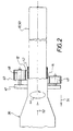
- FIG. 1 shows schematically in a side view commercial vehicle 36 with a (not shown) Baler for making straw or grass bales 38.
- the baler is a wrapper 40 downstream, which has a slewing ring 41, which by a Winding channel element 42 of the vehicle 36 rotates around is drivable. This rotation of the slewing ring 41 is through the arc-shaped arrow 44 illustrates.
- the winding device 40 On the turntable 41 associated with the winding channel element 42 of the winding device 40 are two film coils 46 and 48 stored, of which an outer and an inner Plastic film web 12, 14 (see also Figures 13 and 14) are processed.
- the slewing ring 41 of the In addition to the film coils 46 and 48, the winding device 40 can also a third film wrap for the middle one Have plastic film web 30 (see FIG. 15).
- the slewing ring 41 is in relation to the winding channel element 42 arranged at an angle to the plastic film webs 12 and 14 - and if necessary the central plastic film web 30 - in the same direction helical, axially offset, wrap can.
- FIG. 2 shows a top view of a vehicle 36 with a Winding channel element 42 that clear a circular Cross section.
- Figure 1 shows a Winding channel element 42 with a square clear Channel cross section for bale 38.
- the wrapping channel element 42 circular clear channel cross section (see Figure 2) a winding device 40 with a slewing ring 41 assigned on which film winding 46, 48 arranged are.
- This winding device 40 an endless tube 50 wound that is cut off is indicated.
- the filling material which can be silage, continuously pressed in, which is indicated by the arrow 52.
- the winding device 40 bumps as it were relative to the respective fully pressed hose section 50 from, i.e. it moves according to the feed Arrow 52 relatively in the opposite direction what is indicated by the arrow 54.
- the individual Bale 38 from each other a certain distance, i.e. they are decoupled from each other.
- the distance between the adjacent bale 38 is of cross-sectional dimensions of the goods to be wrapped or of the Cross-sectional dimensions of the individual bales 38 dependent, it can be more than one meter.
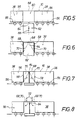
- the decoupling of the neighboring bale 38 is particularly necessary if not only the peripheral surface 56 of the individual bales 38 is wrapped with a hose 10, but if also the mutually facing end faces 58 of the individual bales 38 with the corresponding Hose sections hammered in and tightly closed become. This is in Figures 5 to 8 or in the figures 9 to 12 clarifies.
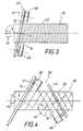
- Fig. 3 shows sections of a hose 10 consisting of Plastic film webs 12 and 14 made from film wraps 46, 48 axially offset from one another in the same winding direction handled, i.e. to an unsigned one Winding channel element wound up and from this as a hose 10 are deducted.
- the two film rolls 46, 48 are on a slewing ring 41 of a winding device 40 is rotatable stored.
- the slewing ring 41 is against the longitudinal axis of the Hose 10 arranged inclined and about its central axis can be driven in rotation, as indicated by the curved arrow 44 is made clear.
- the reference number 22 is the adhesive-free outside of the quasi endless hose 10 called. As before has been described above, the hose 10 is also on its inside is glue-free.
- FIG. 4 shows a representation similar to FIG. 3 sections of a quasi endless hose 10 Plastic sheeting 12 and 14.
- plastic sheeting 12 and 14 are, for example, suitable pre-stretched plastic sheeting, which is associated with Foil rolls 46, 48 wound up and from said Foil coils 46, 48 are unwound.
- the film wrap 46 is on a first slewing ring 41 and the film roll 48 is on a second slewing ring 41 of the winding device 40 rotatably mounted.
- the two slewing rings 41 are about theirs Center axis can be driven in rotation, which is also shown in FIG. 4 the arc-shaped arrows 44 is illustrated.
- the Slewing rings 41 are in the axial direction of each other Hose 10 or one (not shown) Winding channel element axially spaced apart arranged. Each slewing ring 41 closes with said one Longitudinal axis of the hose 10, for example, an angle of on the order of 45 to 60 °. The slewing rings 41 close an angle of in the order of 60 to 90 °. By such Orientation of the slewing rings 41 of the winding device 40 there is a hose 10 with intersecting Plastic sheeting 12 and 14.
- This crossing of Plastic film webs 12, 14 have the advantage that with pre-stretched plastic sheeting 12, 14 with correspondingly increased strength in the longitudinal direction of the film web due to the crosswise winding and gluing the plastic film web 12, 14 the strength in Transverse direction of each of the plastic film webs 12, 14 through the corresponding longitudinal direction strength accordingly is improved.
- This crosswise winding and Adhesion of the plastic film web 12, 14 results thus a hose 10, as it were in all directions has excellent strength.
- FIG. 5 shows two spaced bales 38, of which of the bales 38 drawn on the left side only is shown in sections.
- the hose 10 covers the Circumferential surface 56 of each bale 38.
- the hose 10 but also extends with one corresponding winding connection section 60 between the adjacent and spaced square bales 38.
- This winding connection section 60 between adjacent and spaced square bales 38 can be realized in that the for example with a continuously running pressing process resulting additional need for hose 10 to bridge the Distance between the adjacent bales 38 by a Increase in the rotational speed of the winding device 40 and an adapted increase in bale feed is realized.
- the wrapping process must be completed before the next square bale 38 from the Winding channel element 42 (see FIG.
- the film web protrusions 70 for example, with the help of flap elements folded inwards so that the Film web protrusions 70 on the end faces 58 of the Square bales 38 fit tightly. This is it that is, one to the first fold according to FIG. 6
- Subsequent second folding of the film web protrusions 70 Simultaneously with this second folding, for example Welding takes place in the horizontal plane of the twice folded film web protrusions 70.
- the film web protrusions 70 for example pressed down by means of two flaps, which is indicated in Figure 8 by the arrows 72.
- Figures 9 to 12 illustrate in a spatial Presentation of the individual process steps according to the Figures 5 to 8, so that it is unnecessary in connection with Figures 9 to 12 all the details as in Connection shown with Figures 5 to 8 and are described again.
- the figures 10, 11 and 12 clearly illustrate the first, the second and third folds to a square bale 38 associated film web protrusions 70.
- welding can be carried out via the Diagonals of the end faces 58 to cover the bale 38 respectively. This prevents wrinkling.
- Two welding bars (not shown) can be used here the outer corner points starting diagonally in the middle getting together.
- winding channel element 42 is expedient for the winding channel element 42 to be somewhat conical to design.
- Bale guidance through the extended wrapping channel element 42 can be of various types, for example hydraulic (similar to the hydraulic bale output in known Pressing).
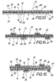
- Figure 13 shows a section of a section of a Hose 10 made of an outer plastic film web 12 and consists of an inner plastic film sheet 14.
- the outer plastic film web 12 is at its inner plastic film web 14 facing inside 16 provided with an adhesive 18.
- the inner plastic film web 14 is on the outer plastic film web 12 facing outside 20 also with a Provide adhesive 18.
- the outer plastic film web 12 and the inner Plastic film web 14 are helical, axially offset from each other, overlapping on the Winding channel element 42 (see FIGS. 1 and 2) in this way wound that the finished hose 10 on its outside 22 and on its inside 24 is adhesive-free. You can the plastic film webs 12 and 14 in the same direction, i.e. in the same angle to each other are wound in parallel.
- plastic film webs 12 and 14 it is also possible to use the plastic film webs 12 and 14 to cross each other, in particular with pre-stretched plastic sheeting 12 and 14 not only in Longitudinal film to excellent strength achieve, but also in the transverse direction of the film webs, because then the longitudinal strength of a film web comparatively small strength in the transverse direction at the other film web - and vice versa - compensates for how already explained above in connection with FIG. 4 has been.
- FIG. 14 shows a section of the Hose 10 from an outer plastic film web 12 and an inner plastic film web 14, the Do not abut longitudinal edges 26 and 28, but in which the longitudinal edges 26 and 28 overlap. in the the rest is the design of the hose 10 according to FIG. 14 the embodiment of the hose drawn in Figure 13 10 similar, so that the further details that in Figure 14 with the same reference numerals as in Figure 13 are not described again in detail.
- Figure 15 shows in a similar to Figures 13 and 14 Representation of a section of the hose 10 with a middle plastic film web 30 attached to both of them Pages 32 and 34 are each provided with an adhesive 18, and with an outer plastic film web 12 and with an inner plastic film web 14 together helical, axially offset from each other overlapping, on a winding channel element 42 (see FIGS. 1 and 2) are wound. Even with such training can the plastic film webs 12, 14 and 30 in same winding sense parallel to each other or themselves be wrapped crosswise to a uniform high Strength of the hose 10 in all directions achieve.
Abstract
Description
Die Erfindung betrifft ein Verfahren zur Herstellung eines Schlauches aus Kunststoff-Folienmaterial, wobei eine äußere und eine innere Kunststoff-Folienbahn schraubenlinienförmig, axial gegeneinander versetzt, sich überlappend gewickelt werden.The invention relates to a method for producing a hose from plastic film material, with an outer and an inner plastic film web helical, axially offset from one another, wound overlapping become.
Ein Schlauch aus Kunststoff-Folienmaterial kann bspw. dadurch hergestellt werden, daß ein Folienstreifen um eine zu seiner Längsrichtung parallele Achse aufgebogen wird und die beiden Längsränder dann miteinander verschweißt werden. Eine solche Längsverschweißung erlaubt jedoch nur eine begrenzte Streckung bzw. Reckung der Folie, so daß die mechanische Festigkeit der Folie bzw. des Schlauches aus Kunststoff-Folienmaterial Wünsche offen läßt.A hose made of plastic film material can be produced, for example, by that a film strip is bent around an axis parallel to its longitudinal direction and the two longitudinal edges are then welded together. Such Longitudinal welding, however, allows only a limited stretching or stretching of the Foil, so that the mechanical strength of the film or the tube Plastic film material leaves nothing to be desired.
Aus der EP 0 005 278 B1 ist ein Verfahren zur Herstellung eines Schlauches bekannt, wobei eine äußere und eine innere Kunststoff-Folienbahn gemeinsam mit einem ersten und einem zweiten Draht gewickelt werden. Der erste und der zweite Draht werden parallel schraubenförmig zweigängig angeordnet, wobei sich die aufeinanderfolgenden Windungen abwechseln. Die innere Kunststoff-Folienbahn wird schraubenförmig um das von den Windungen der ersten Drähte gebildete rohrförmige Längenstück gewickelt, wobei die innere Kunststoff-Folienbahn breiter ist als der Doppelgang jedes Drahtes. Der vordere und der hintere Randabschnitt der inneren Kunststoff-Folienbahn überlappen einander über den Windungen des ersten Drahtes. Die äußere Kunststoff-Folienbahn ist schraubenförmig um die innere Kunststoff-Folienbahn gewickelt und breiter als die doppelte Ganghöhe der Drähte. Der vordere und der hintere Randabschnitt der äußeren Kunststoff-Folienbahn überlappen einander über den Windungen des zweiten Drahtes.A method for producing a hose is known from EP 0 005 278 B1, an outer and an inner plastic film web together with a first and a second wire are wound. The first and second wire will be arranged in parallel helical two-course, the successive Alternate turns. The inner plastic film web is screwed around the tubular length piece formed by the turns of the first wires wrapped, the inner plastic film web is wider than the double course of each Wire. The front and the rear edge section of the inner plastic film web overlap each other over the turns of the first wire. The outer plastic film is helically wrapped around the inner plastic sheet and wider than twice the pitch of the wires. The front and the back Edge section of the outer plastic film overlap each other over the Second wire turns.
Aus der EP 0 315 506 A1 ist ein Verfahren zur Herstellung von Rohrstücken aus Kunststoff-Folienbahnen bekannt, wobei eine Anzahl Kunststoff-Folienbahnen schraubenlinienförmig, axial gegeneinander versetzt, sich überlappend, auf einen langen Dorn aufgewickelt werden. Nach einer Wärmebehandlung zur Polymerisation erfolgt ein Auseinandertrennen in die einzelnen Rohrstücke.EP 0 315 506 A1 describes a method for producing pipe sections Plastic sheeting known, with a number of plastic sheeting helical, axially offset, overlapping, on one long thorn can be wound up. After heat treatment for polymerization the individual pieces of pipe are separated.
Die EP 0 027 677 A1 beschreibt ein Verfahren zur Herstellung von Verpackungsbehältern aus bandförmigem Material, bestehend aus einer Polyesterfolie mit monoaxialer Molekülorientierung. Das Polyesterband wird spiralförmig auf einen Dorn gewickelt, um einen Schlauch zu bilden. Die Randzonen der aufeinanderfolgenden Windungen des Folienbandes wird zu höchstens 15 % der Bandbreite in gegenseitige Überlappung gebracht. Die Verbindung erfolgt mittels eines Klebers oder mittels einer Oberflächenverschmelzung im Überlappungsbereich der Windungen. Der gebildete Schlauch wird zu hülsenförmigen Behälterkörpern bestimmter Länge zugeschnitten. Die hülsenförmigen Behälterkörper werden mit Endwänden versehen, welche die Hülsenöffnungen verschließen. Bei diesem Verfahren wird nur ein Folienband auf den erwähnten Dorn aufgebracht. Die Breite des Folienbandes beträgt 75 bis 150 % des Schlauchdurchmessers. Das Abdichten der Überlappungszonen erfolgt mit Hilfe ortsfester Dichtungselemente, die in bestimmter Beziehung zueinander angeordnet sind, und deren Lage so gewählt ist, daß sie nahe an der Überlappungszone positioniert sind, die kontinuierlich an den Dichtungselementen vorbeigeführt wird. EP 0 027 677 A1 describes a process for the production of Packaging containers made of tape-like material, consisting of a polyester film with monoaxial molecular orientation. The polyester tape is spiraled onto one Mandrel wrapped to form a tube. The marginal zones of the consecutive turns of the foil tape will not exceed 15% of the Bandwidth overlapped. The connection is made using a Adhesive or by means of a surface fusion in the overlap area of the Coils. The tube formed becomes tubular container bodies cut to a certain length. The sleeve-shaped container body are with Provide end walls that close the sleeve openings. With this The method only applies a film strip to the mandrel mentioned. The width of the Foil tape is 75 to 150% of the tube diameter. Sealing the Overlap zones are carried out with the help of stationary sealing elements, which in certain Relationship to each other are arranged, and their position is chosen so that they are close are positioned at the overlap zone that are continuously on the Sealing elements is passed.
Ein Verfahren zur Herstellung eines Schlauches aus einer Kunststoff-Folienbahn ist auch aus der FR-A 2 464 820 bekannt. Auch dort kommt nur eine einzige Kunststoff-Folienbahn zur Anwendung, die bspw. auch überlappend gewickelt wird.One method for producing a tube from a plastic film web is also known from FR-A 2 464 820. There is also only one single plastic film web there for use, which is also overlapped, for example.
Aus der US-A-4 058 427 ist eine Vorrichtung bekannt, die zum Umwickeln eines Rohres mit mindestens einem Wickelstreifen vorgesehen ist. Der mindestens eine Wickelstreifen ist einseitig mit einem Kleber beschichtet. Die Kleberbeschichtung ist ursprünglich mit einem Abdeckstreifen bedeckt. Der mit dem Abdeckstreifen bedeckte Wickelstreifen ist auf einen Wickeldom aufgewickelt, der an der Vorrichtung gelagert ist. Im Betrieb der Vorrichtung wird der Abdeckstreifen vom Wickelstreifen abgezogen und der Wickelstreifen mit seiner Kleberbeschichtung am zu umwickelnden Rohr festgelegt. Diese bekannte Vorrichtung dient also nicht zur Herstellung eines Schlauches sondern zum Umwickeln eines Rohres.From US-A-4 058 427 a device is known which is for wrapping a Tube with at least one winding strip is provided. The at least one Wrapping strip is coated on one side with an adhesive. The adhesive coating is originally covered with a masking tape. The one covered with the masking tape Wrapping strip is wound on a winding dome, which is mounted on the device is. During operation of the device, the cover strip is pulled off the winding strip and the winding strip with its adhesive coating on the pipe to be wrapped fixed. This known device is therefore not used to produce a Hose but for wrapping a pipe.
Die EP-A-0 224 766 beschreibt ein Wickelverfahren zum Umwickeln eines Stapels bzw. eines Gebindes aus einer Anzahl Gegenstände, wobei das jeweilige Gebinde an Wickelstationen mit einer Folie umwickelt wird. Auch hier handelt es sich nicht um ein Verfahren zur Herstellung eines Schlauches, insbesondere eines endlosen Schlauches, sondern um ein Verfahren zum Umwickeln eines formstabilen Stapels bzw. Gebindes.EP-A-0 224 766 describes a winding method for wrapping a stack or a bundle of a number of objects, the respective bundle on Winding stations is wrapped with a film. Again, this is not a Method of manufacturing a hose, especially an endless one Tube, but a method for wrapping a dimensionally stable stack or container.
Aus der US-A-5 155 970 ist ein Verfahren zum Umwickeln eines Gegenstandes mit einem Folienstreifen bekannt, der an einer Seite eine Kleberbeschichtung aufweist. Der Folienstreifen wird auf den Gegenstand aufgewickelt, wobei die Kleberbeschichtung vom Gegenstand abgewandt ist. Nach diesem ersten Aufwickelvorgang wird der Folienstreifen derartig umgekehrt, daß die Kleberbeschichtung dem Gegenstand zugewandt ist. Gleichzeitig wird die Wickelrichtung umgekehrt, so daß sich eine zweilagige Wicklung aus einem einzigen Folienstreifen ergibt, wobei die Kleberbeschichtungen der beiden Wickellagen einander zugewandt vorgesehen sind und die Innen- und die Außenseite der zweilagigen Wicklung kleberfrei ist. Bei diesem bekannten Verfahren wird also aus einem einzigen Folienstreifen ein zweilagiges Wickelgebilde endlicher Länge hergestellt.From US-A-5 155 970 is a method for wrapping an object with a film strip known, which has an adhesive coating on one side. The Film strip is wound onto the object, leaving the adhesive coating is turned away from the object. After this first winding process the Film strips reversed so that the adhesive coating the object is facing. At the same time, the winding direction is reversed, so that there is a two-layer winding results from a single film strip, the Adhesive coatings of the two winding layers are provided facing each other and the inside and outside of the two-layer winding is glue-free. With this Known methods thus become a two-layer from a single film strip Finished length winding structures produced.
Die US-A-4 409 776 offenbart ein Verfahren und eine Vorrichtung zum Umwickeln von Gegenständen mit einem Streifenmaterial, das an einer Seite mit einem Kleber versehen ist. Hierbei wird das Streifenmaterial in einem ersten Verfahrensschritt spiralförmig um den Gegenstand herumgewickelt, wobei der Kleber auf der vom Gegenstand abgewandten Seite des Streifenmaterials vorgesehen ist. Nach Abschluß dieses ersten Verfahrensschrittes wird das Streifenmaterial um 180° gedreht und spiralförmig am Gegenstand zurückgewickelt. Auf diese Weise ergibt sich - wie bei der oben genannten US-A-5 155 970 - eine zweilagige Umhüllung des Gegenstandes derart, daß die beiden Lagen durch ihre Kleberbeschichtung miteinander verbunden und die Innen- und die Außenseite der zweilagigen Umhüllung kleberfrei ist. Auch hier wird nur ein einziger Streifen verwendet, um den Gegenstand zu umhüllen. Zur Herstellung eines endlosen Schlauches ist auch dieses bekannte Verfahren nicht geeignet.US-A-4 409 776 discloses a method and apparatus for wrapping Items with a striped material on one side with an adhesive is provided. The strip material is used in a first process step spirally wrapped around the object, with the glue on the from The side of the strip material facing away from the object is provided. After graduation this first process step, the strip material is rotated through 180 ° and wrapped spirally on the object. In this way - as with the above-mentioned US-A-5 155 970 - a two-layer wrapping of the article such that the two layers are connected by their adhesive coating and the inside and outside of the two-layer wrapper is glue-free. Here too only a single strip is used to wrap the item. For This known method is also not a production of an endless hose suitable.
Der Erfindung liegt die Aufgabe zugrunde, ein Verfahren der eingangs genannten Art zu schaffen, das eine vergleichsweise starke Vorstreckung bzw. Vorreckung der Kunststoffolie erlaubt, so daß sich die mechanische Festigkeit des hergestellten Schlauches erheblich steigern läßt, wobei der erfindungsgemäß hergestellte Schlauch zur Verpackung und zum Schutz der verpackten Güter ausgezeichnet geeignet ist.The invention has for its object a method of the type mentioned to create a comparatively strong pre-stretching or pre-stretching of the Plastic film allowed, so that the mechanical strength of the manufactured Hose can be increased significantly, the hose produced according to the invention for packaging and protecting the packaged goods.
Diese Aufgabe ist bei einem gattungsgemäßen Verfahren dadurch gelöst, daß mindestens eine der beiden voneinander unabhängigen, gleichzeitig gewickelten Kunststoff-Folienbahnen an ihrer der anderen Kunststoff-Folienbahn zugewandten Seite einen Kleber aufweist, und die Kunststoff-Folienbahnen so gewickelt werden, daß der Schlauch an seiner Außen- und an seiner Innenseite kleberfrei ist. Bei der Durchführung dieses Verfahrens kann eine äußere und eine innere Kunststoff-Folienbahn zur Anwendung gelangen, von welchen jede an ihrer der anderen Kunststoff-Folienbahn zugewandten Seite einen Kleber aufweist. Bei dem besagten Kleber handelt es sich um eine Klebeschicht oder um Haftadditive.This object is achieved in a generic method in that at least one of the two independent, simultaneously wound plastic film webs one on their side facing the other plastic film web Has adhesive, and the plastic film webs are wound so that the Hose is adhesive-free on the outside and inside. In the Carrying out this method can be an outer and an inner plastic film web come into use, each on their own Plastic side facing the film has an adhesive. With the said Adhesive is an adhesive layer or adhesive additives.
In vorteilhafter Weise gelangen anstelle von zwei Kunststoff-Folienbahnen drei Kunststoff-Folienbahnen zur Anwendung, d.h. eine mittlere Kunststoff-Folienbahn, die an ihren beiden Seiten jeweils einen Kleber aufweist wird, mit einer äußeren und einer inneren Kunststoff-Folienbahn schraubenlinienförmig, axial gegeneinander versetzt, sich überlappend gleichzeitig derart gewickelt, daß der Schlauch an seiner Außen- und an seiner Innenseite kleberfrei ist.Advantageously, instead of two plastic film webs, three plastic film webs arrive for use, i.e. a medium-sized plastic film web, which has an adhesive on each of its two sides, with one outer and one inner plastic film sheet helical, axially offset from each other, overlapping at the same time so that the hose on his Outside and inside is glue-free.
Erfindungsgemäß werden also mindestens zwei Kunststoff-Folienbahnen schraubenlinienförmig derartig gewickelt, daß ein Schlauch entsteht, dessen Außenseite und dessen Innenseite frei von Klebeschichten oder Haftadditiven ist. Dadurch, daß die Außen- und die Innenseite des erfindungsgemäß hergestellten Schlauches frei von Klebeschichten oder Haftadditiven ist, ergibt sich der Vorteil, daß der Schlauch problemlos wunschgemäß verschweißbar sind. Ein weiterer Vorteil des erfindungsgemäß hergestellten Schlauches, der an seiner Außen- und Innenseite von Klebeschichten oder Haftadditiven frei ist, besteht darin, daß der Schlauch problemlos von einem Wickelkanalelement abziehbar ist. Dadurch, daß die Innenseite des erfindungsgemäß hergestellten Kunststoffolien-Schlauches frei von Klebeschichten oder Haftadditiven ist, ergibt sich eine ausgezeichnete Gleitfähigkeit der inneren Kunststoff-Folienbahn und des fertigen Schlauches. Diese Gleitfähigkeit ist insbes. dann von Bedeutung bzw. vorteilhaft, wenn bei einer Bewicklung eines zu verpackenden Gutes auf das Packgut kein Kleber gelangen soll. Der Schlauch kann auf dem Wickelkanalelement vorgefertigt und von diesem abgezogen wird.According to the invention, at least two plastic film webs helically wound such that a hose is formed, the The outside and the inside of it are free of adhesive layers or adhesive additives. The fact that the outside and the inside of the manufactured according to the invention Hose is free of adhesive layers or adhesive additives, there is the advantage that the hose can be easily welded as desired. Another advantage of Hose produced according to the invention, which on its outside and inside of Adhesive layers or adhesive additives is free, that the hose is easy is removable from a winding channel element. The fact that the inside of the Plastic film tube produced according to the invention free of adhesive layers or adhesive additives is an excellent result Slidability of the inner plastic film and the finished hose. This lubricity is then especially of importance or advantageous when wrapping of a good to be packed on the packaged goods no glue should arrive. The hose can be on the winding channel element prefabricated and subtracted from this.
Der durch die Verklebung von zwei oder drei Folienbahnen erfindungsgemäß hergestellte Schlauch kann zum Schutz bzw. zur Verpackung beliebiger Güter wie bspw. Gras- oder StrohBallen, zur Verpackung von Koffern oder anderen Transportbehältnissen, zum Verpacken von auf Paletten stehenden Kraftfahrzeugen o.dgl. zur Anwendung gelangen. Wird der erfindungsgemäße Schlauch auf einem Wickelkanalelement vorgefertigt, so ist es in vorteilhafter Weise möglich, mit jeweils ähnlichen bzw. gleichen Kunststoff-Folienbahnen durch Änderung der Form bzw. der Abmessungen des Wickelkanalelementes die lichten Rohr-Querschnittsabmessungen in Anpassung an das zu verpackende Gut wunschgemäß zu variieren. Ausgehend von einer definierten Stärke der Kunststoff-Folienbahnen ist erfindungsgemäß in vorteilhafter Weise außerdem eine wunschgemäße Variation der Wandstärke der hergestellten Schlauchfolie durch den Grad der Überlappung der Kunststoff-Folienbahnen und/oder durch die Intensität der Vorreckung der Kunststoff-Folienbahnen möglich. Der Überlappungsgrad ist hierbei vom Verhältnis von Wickelgeschwindigkeit und Vorschub abhängig. Bei handelsüblichen Stretchfolien ist eine Vorreckung der Kunststoff-Folienbahnen bspw. bis größenordnungsmäßig 500 % realisierbar. Durch eine solche Vorreckung ergibt sich eine Festigkeitserhöhung der Folienbahnen in ihrer Längsrichtung. The one by gluing two or three sheets of film Hose produced according to the invention can be used for protection or for packing any goods such as grass or straw bales, for packing suitcases or others Transport containers, for packaging on pallets stationary vehicles or the like. apply. If the hose according to the invention on a Prefabricated winding channel element, so it is more advantageous Possible way, with similar or the same Plastic film webs by changing the shape or Dimensions of the winding channel element the clear tube cross-sectional dimensions in line with what is to be packaged Vary as desired. Starting from one defined thickness of the plastic film webs according to the invention advantageously also a desired variation of the wall thickness of the manufactured Tubular film by the degree of overlap of the Plastic sheeting and / or by the intensity of the It is possible to stretch the plastic sheeting. The The degree of overlap is the ratio of Winding speed and feed dependent. At commercially available stretch films is an advance of the Plastic sheeting, for example up to the order of 500% realizable. Such a stretching results in one Strengthening of the film webs in their Longitudinal direction.
Erfindungsgemäß können die äußere und die innere Kunststoff-Folienbahn mit ihren Längsrändern jeweils aneinander angrenzend gewickelt werden. Bei einer solchen Vorgehensweise ist die Wandstärke des fertigen Schlauches durch die Intensität der Vorreckung der Kunststoff-Folienbahnen wunschgemäß variier- bzw. einstellbar. Wie bereits erwähnt worden ist, können bei Durchführung des erfindungsgemäßen Verfahrens die äußere und die innere Kunststoff-Folienbahn mit ihren Längsrändern überlappend gewickelt werden, so daß die Stärke des erfindungsgemäß hergestellten Schlauches nicht nur durch die Intensität der Vorreckung der Kunststoff-Folienbahnen sondern auch durch den Grad der Überlappung wunschgemäß einstellbar ist. Gleichzeitig wird durch die Vorreckung - wie bereits erwähnt worden ist - die Festigkeit der Folienbahnen in ihrer Längsrichtung erhöht. Erfindungsgemäß geht also eine Wanddickenreduktion in vorteilhafter Weise mit einer Festigkeitserhöhung einher.According to the invention, the outer and inner Plastic film web with its longitudinal edges each be wrapped adjacent to each other. With one The procedure is the wall thickness of the finished hose by the intensity of the pre-stretching of the plastic film webs can be varied or adjusted as required. How has already been mentioned, can be carried out when the inventive method, the outer and the inner Plastic film web with their longitudinal edges overlapping be wound so that the strength of the invention manufactured hose not only by the intensity of the Stretching the plastic sheeting also through the degree of overlap is adjustable as desired. At the same time, by pre-stretching - as already has been mentioned - the strength of the film webs in their longitudinal direction increased. According to the invention, one goes Wall thickness reduction in an advantageous manner with a Strength increase accompanied.
Wie ebenfalls bereits ausgeführt worden ist, können bei der Durchführung des erfindungsgemäßen Verfahrens die Kunststoff-Folienbahnen auf ein Wickelkanalelement aufgewickelt werden, das einen runden oder einen eckigen Kanalquerschnitt besitzen kann. Das Wickelkanalelement kann selbstverständlich jeden beliebigen, mehr oder weniger balligen Kanalquerschnitt besitzen. Es ist auch möglich, daß die Kunststoff-Folienbahnen unter Ausbildung eines Schlauches auf das jeweilige zu verpackende Gut direkt aufgewickelt werden.As has also already been stated, the Carrying out the method according to the invention Plastic sheeting on a winding channel element be wound up, a round or an angular Can have cross-section. The winding channel element can of course any, more or less possess a spherical channel cross-section. It is also possible, that the plastic sheeting with formation of a Hose directly onto the goods to be packaged be wound up.
Bei der Durchführung des erfindungsgemäßen Verfahrens können die Kunststoff-Folienbahnen auf das Wickelkanalelement im gleichen Wickelsinn gegeneinander axial versetzt aufgewickelt werden. Nachdem die Festigkeit der Folienbahnen durch die erwähnte Vorreckung nur in Längsrichtung der Folienbahnen erhöht wird, d.h. die Festigkeit der Folienbahnen in ihrer Querrichtung sich nicht erhöht, ergibt sich auf diese Weise ein Schlauch, bei welchem die Festigkeit in Querrichtung kleiner ist als in Längsrichtung der Folienbahnen. Eine solche unterschiedliche Festigkeit des Schlauches in Längs- und Querrichtung der Folienbahnen kann eliminiert werden, wenn die Kunststoff-Folienbahnen auf das Wickelkanalelement sich überkreuzend aufgewickelt werden. Durch eine solche sich überkreuzende Wicklung der Folienbahnen ergibt sich ein Schlauch, der in allen Richtungen eine mindestens annähernd gleich hohe Festigkeit besitzt. Ein solchermaßen hergestellter Kunststoff-Folienschlauch eignet sich bspw. ganz besonders gut zum dichten Einhüllen von Packgütern mit sich stark ändernden Konturen wie bspw. Personenkraftwagen usw.When carrying out the method according to the invention can the plastic sheeting on the Winding channel element in the same winding direction against each other be wound axially offset. After the firmness of the film webs due to the aforementioned stretching only in Longitudinal direction of the film webs is increased, i.e. the Strength of the film webs in their transverse direction not increased, this results in a hose, at which the strength in the transverse direction is smaller than in Longitudinal direction of the film webs. Such different strength of the hose in longitudinal and Transverse direction of the film webs can be eliminated if the plastic sheeting on the winding channel element itself be wound up crosswise. Through such yourself there is a crossing winding of the film webs Hose that is at least approximately in all directions has the same high strength. Such a way The plastic film tube produced is suitable, for example. especially good for tightly wrapping packaged goods with rapidly changing contours such as passenger cars etc.
Unabhängig davon, ob die Folienbahnen im gleichen Wickelsinne gegeneinander axial versetzt oder sich überkreuzend gewickelt werden, ergibt sich ein Schlauch, der an seiner Innenseite und der an seiner Außenseite kleberfrei ist.Regardless of whether the film webs in the same Winding sense axially offset from each other or themselves wrapped crosswise, you get a tube, the one on the inside and the one on the outside is glue-free.
Die Geschwindigkeit des Abzuges des Schlauches vom Wickelkanalelement muß mit dem Tempo der Folienumwicklung - unabhängig davon, ob gleichsinnig oder überkreuzend gewickelt wird - im Einklang stehen. D.h. wenn der Abzug unterbrochen wird, steht auch die Folienumwicklung still. Startet der Abzug, beginnt auch sofort die Folienumwicklung wieder zu laufen.The speed of hose withdrawal from Winding channel element must be at the speed of film wrapping - regardless of whether they are in the same direction or cross over is wrapped - be in line. I.e. if the deduction is interrupted, the film wrapping also stops. When the deduction starts, the film wrapping begins immediately to run again.
Der erfindungsgemäß hergestellte Schlauch aus Kunststoff-Folienbahnen kann bspw. auf voneinander beabstandete Vierkantballen aufgewickelt werden. Dabei wird der Wickelverbindungsabschnitt zwischen benachbarten, voneinander beabstandeten Vierkantballen mindestens annähernd mittig durchtrennt.The hose made according to the invention from plastic film webs can, for example, be spaced apart Square bales are wound up. The winding connection section at least between adjacent square bales spaced from each other cut almost in the middle.
Dies kann zum einen dadurch erfolgen, daß die Wickelverbindungsabschnitte mit Hilfe von zwei vertikal beweglichen Holmen auf halber Ballenhöhe flachgelegt und anschließend zwischen den beiden Holmen mit einer geeigneten Schweißvorrichtung, z.B. Doppelschweißnaht mit mittiger Trennung, abgeschweißt und getrennt werden.This can be done on the one hand by using the winding connection sections flattened by two vertically movable bars at half the height of the bale and then between the two bars with a suitable welding device, e.g. Double weld seam with central separation, welded and separated.
Zum anderen können die sich ergebenden Folienbahnüberstände an den einander zugewandten Stirnflächen der jeweils benachbarten Vierkantballen umgefaltet eingeschlagen und dicht verschweißt werden. Bei den genannten Vierkantballen handelt es sich z.B. um Stroh- oder Grasballen. Bei Strohballen dient der erfindungsgemäß hergestellte Schlauch zum Wetterschutz für die Strohballen. Bei Grasballen dient der erfindungsgemäß hergestellte Schlauch sowohl zur Realisierung eines Wetterschutzes als auch zum Silieren der Grasballen. Das erfindungsgemäße Verfahren kann mit einer an sich bekannten Vierkant-Ballenpresse kombiniert sein; es kann jedoch auch an einer von einer solchen Ballenpresse getrennten, unabhängigen Wickelmaschine durchgeführt werden. On the other hand, the resulting film web protrusions on the each other facing end faces of the adjacent square bales folded hammered in and welded tight. With the mentioned square bales is it e.g. around bales of straw or grass. This is used for straw bales Hose according to the invention for weather protection for the straw bales. At The hose produced according to the invention is used for grass bales both for implementation of weather protection as well as for ensiling the grass bales. The invention The method can be combined with a square baler known per se; it can, however, also on an independent of such a baler Winding machine can be carried out.
Erfindungsgemäß kann ein Endlosschlauch hergestellt werden, der bspw. zum Verpacken von Silage verwendet wird. Hierbei kann die Silage kontinuierlich in den erfindungsgemäß hergestellten Endlos-Schlauch gepreßt werden, wobei sich das zur Herstellung des Schlauches dienende Wickelgerät von dem jeweils bereits gepreßten Schlauchvorderabschnitt abstößt und sich dem Vorschub entsprechend auf die zur Vorschubbewegung des Schlauches entgegengesetzte Richtung bewegt.According to the invention, an endless hose can be produced, for example for Packaging silage is used. Here, the silage can continuously in the Continuous hose produced according to the invention are pressed, which is the Production of the hose-serving winding device from the one already pressed Hose front section repels and according to the feed to the Feed movement of the hose moves in the opposite direction.
Weitere Einzelheiten ergeben sich aus der nachfolgenden Beschreibung von in der Zeichnung schematisch dargestellten Abschnitten des erfindungsgemäß hergestellten Schlauches sowie von Anwendungen des erfindungsgemäßen Schlauches an schematisch gezeichneten Maschinen. Es zeigen:
Figur 1- schematisch in einer Seitenansicht teilweise aufgeschnitten ein Fahrzeug mit einer Ballenpresse und einer Wickelvorrichtung zum Umwickeln von Ballen,
- Figur 2
- in einer Ansicht von oben eine andere Ausbildung eines Fahrzeuges mit einer Wickelvorrichtung zur Herstellung einer sog. Endloswicklung bzw. eines Endlosschlauches, der abgeschnitten gezeichnet ist, für Rundballen,
- Figur 3
- abschnittweise einen Schlauch aus mindestens zwei Kunststoff-Folienbahnen in Kombination mit einer zugehörigen Wickelvorrichtung, wobei die Kunststoff-Folienbahnen axial gegeneinander versetzt im gleichen Wickelsinn auf ein (nicht gezeichnetes) Wickelkanalelement aufgewickelt und von diesem abgezogen werden,
- Figur 4
- in einer der Figur 3 ähnlichen Darstellung abschnittweise einen Schlauch aus Kunststoff-Folienbahnen, die mit Hilfe einer geeignet ausgebildeten Wickelvorrichtung kreuzweise auf ein (nicht gezeichnetes) Wickelkanalelement aufgewickelt und von diesem abgezogen werden,
- Figuren 5, 6, 7 und 8
- aufeinanderfolgende Verfahrensschritte zum allseitigen Verschließen benachbarter und voneinander beabstandeter Ballen mit einem Schlauch aus Kunststoff-Folienbahnen,
Figuren 9, 10, 11und 12- die den Figuren 5 bis 8 entsprechenden Verfahrensschritte in einer räumlichen Darstellung zur weiter verbesserten Verdeutlichung der einzelnen Verfahrensschritte,
- Figur 13
- in einer Schnittdarstellung vergrößert und
nicht maßstabsgerecht einen Abschnitt einer
ersten Ausbildung des mit einer
Vorrichtung gemäß Figur 1 oder 2 bzw. gemäß Fig. 3 oder 4 hergestellten Schlauches, Figur 14- in einer der Figur 13 ähnlichen Darstellung
einen Abschnitt einer zweiten Ausführungsform
des mit einer
Vorrichtung gemäß Figur 1 oder 2 bzw. gemäß Figur 3 oder 4 hergestellten Schlauches, und - Figur 15
- in einer den Figuren 13 und 14 ähnlichen
Darstellung einen Abschnitt einer dritten
Ausbildung des mit einer
Wickelvorrichtung gemäß Figur 1 oder 2 bzw. gemäß Figur 3 oder 4 hergestellten Schlauches.
- Figure 1
- schematically in a side view partially cut open a vehicle with a baler and a wrapping device for wrapping bales,
- Figure 2
- another view of a vehicle with a winding device for producing a so-called endless winding or an endless tube, which is shown cut off, for round bales, in a view from above,
- Figure 3
- sections of a tube made from at least two plastic film webs in combination with an associated winding device, the plastic film webs being wound axially offset from one another in the same winding direction on a (not shown) winding channel element and being pulled off this,
- Figure 4
- in a representation similar to FIG. 3, a section of a tube made of plastic film webs, which are wound crosswise onto a (not shown) winding channel element with the aid of a suitably designed winding device, and are pulled off this,
- Figures 5, 6, 7 and 8
- successive process steps for all-round sealing of adjacent and spaced-apart bales with a tube made of plastic film webs,
- Figures 9, 10, 11 and 12
- the process steps corresponding to FIGS. 5 to 8 in a spatial representation to further clarify the individual process steps,
- Figure 13
- a sectional view enlarged and not to scale a section of a first embodiment of the hose manufactured with a device according to FIG. 1 or 2 or according to FIG. 3 or 4,
- Figure 14
- in a representation similar to FIG. 13, a section of a second embodiment of the hose produced with a device according to FIG. 1 or 2 or according to FIG. 3 or 4, and
- Figure 15
- in a representation similar to FIGS. 13 and 14, a section of a third embodiment of the hose produced with a winding device according to FIG. 1 or 2 or according to FIG. 3 or 4.
Figur 1 zeigt schematisch in einer Seitenansicht ein
handelsübliches Fahrzeug 36 mit einer (nicht gezeichneten)
Ballenpresse zur Herstellung von Stroh- oder Grasballen 38.
Der Ballenpresse ist eine Wickelvorrichtung 40
nachgeordnet,die einen Drehkranz 41 aufweist, der um ein
Wickelkanalelement 42 des Fahrzeuges 36 herum rotativ
antreibbar ist. Diese Rotation des Drehkranzes 41 ist durch
den bogenförmigen Pfeil 44 verdeutlicht. Figure 1 shows schematically in a side view
An dem dem Wickelkanalelement 42 zugeordneten Drehkranz 41
der Wickelvorrichtung 40 sind zwei Folienwickel 46 und 48
gelagert, von welchen eine äußere und eine innere
Kunststoff-Folienbahn 12, 14 (sh. auch die Figuren 13 und
14) abgewickelt werden. Der Drehkranz 41 der
Wickelvorrichtung 40 kann außer den Folienwickeln 46 und 48
auch noch einen dritten Folienwickel für die mittlere
Kunststoff-Folienbahn 30 (sh. Figur 15) aufweisen.On the
Der Drehkranz 41 ist in Bezug auf das Wickelkanalelement 42
schräg geneigt angeordnet, um die Kunststoff-Folienbahnen
12 und 14 - und gegebenenfalls die mittige Kunststoff-Folienbahn
30 - im gleichen Wickelsinn
schraubenlinienförmig, axial passend versetzt, wickeln zu
können.The slewing
Figur 2 zeigt in einer Draufsicht ein Fahrzeug 36 mit einem
Wickelkanalelement 42, das einen kreisrunden lichten
Querschnitt besitzt. Demgegenüber zeigt die Figur 1 ein
Wickelkanalelement 42 mit einem viereckigen lichten
Kanalquerschnitt für Ballen 38. Dem Wickelkanalelement 42
kreisrunden lichten Kanalquerschnitts (sh. Figur 2) ist
eine Wickelvorrichtung 40 mit einem Drehkranz 41
zugeordnet, an welchem Folienwickeln 46, 48 angeordnet
sind. Auch hier werden die Kunststoff-Folienbahnen 12 und
14 - und gegebenenfalls zusätzlich eine mittlere Folienbahn
30 (sh. Fig. 15) im gleichen Wickelsinn axial gegeneinander
geeignet versetzt auf das Wickelkanalelement 42
aufgewickelt. Mit Hilfe dieser Wickelvorrichtung 40 wird
ein Endlosschlauch 50 gewickelt, der abgeschnitten
angedeutet ist. In den Endlosschlauch 50 wird das Füllgut,
bei dem es sich um Silage handeln kann, kontinuierlich
hineingepreßt, was durch den Pfeil 52 angedeutet ist. FIG. 2 shows a top view of a
Gleichzeitig stößt sich die Wickelvorrichtung 40 gleichsam
relativ vom jeweiligen vollgepressten Schlauchabschnitt 50
ab, d.h. sie bewegt sich entsprechend dem Vorschub gemäß
Pfeil 52 relativ in die entgegengesetzte Richtung, was
durch den Pfeil 54 angedeutet ist.At the same time, the winding
Wie aus Figur 1 ersichtlich ist, weisen die einzelnen
Ballen 38 voneinander einen bestimmten Abstand auf, d.h.
sie sind voneinander entkoppelt. Der Abstand zwischen den
benachbarten Ballen 38 ist von den Querschnittsabmessungen
des zu umwickelnden Gutes bzw. von den
Querschnittsabmessungen der einzelnen Ballen 38 abhängig,
er kann mehr als einen Meter betragen. Die Entkopplung der
benachbarten Ballen 38 ist insbes. dann notwendig, wenn
nicht nur die Umfangsmantelfläche 56 der einzelnen Ballen
38 mit einem Schlauch 10 umwickelt wird, sondern wenn
außerdem auch die einander zugewandten Stirnseiten 58 der
einzelnen Ballen 38 mit den entsprechenden
Schlauchabschnitten eingeschlagen und dicht verschlossen
werden. Das ist in den Figuren 5 bis 8 bzw. in den Figuren
9 bis 12 verdeutlicht.As can be seen from Figure 1, the
Fig. 3 zeigt abschnittweise einen Schlauch 10 bestehend aus
Kunststoff-Folienbahnen 12 und 14, die von Folienwickeln
46, 48 im gleichen Wickelsinne gegeneinander axial versetzt
abgewickelt, d.h. auf ein nicht gezeichnetes
Wickelkanalelement aufgewickelt und von diesem als Schlauch
10 abgezogen werden. Die beiden Folienwickel 46, 48 sind an
einem Drehkranz 41 einer Wickelvorrichtung 40 drehbar
gelagert. Der Drehkranz 41 ist gegen die Längsachse des
Schlauches 10 geneigt angeordnet und um seine Mittelachse
rotativ antreibbar, was durch den bogenförmigen Pfeil 44
verdeutlicht ist. Fig. 3 shows sections of a
Mit der Bezugsziffer 22 ist die kleberfreie Außenseite des
quasi endlosen Schlauches 10 bezeichnet. Wie bereits weiter
oben beschrieben worden ist, ist der Schlauch 10 auch an
seiner Innenseite kleberfrei.With the
Fig. 4 zeigt in einer der Fig. 3 ähnlichen Darstellung
abschnittweise einen quasi endlosen Schlauch 10 aus
Kunststoff-Folienbahnen 12 und 14. Bei den Kunststoff-Folienbahnen
12 und 14 handelt es sich bspw. um geeignet
vorgereckte Kunststoff-Folienbahnen, die auf zugehörige
Folienwickel 46, 48 aufgewickelt und von den besagten
Folienwickeln 46, 48 abgewickelt werden. Der Folienwickel
46 ist an einem ersten Drehkranz 41 und der Folienwickel 48
ist an einem zweiten Drehkranz 41 der Wickelvorrichtung 40
drehbar gelagert. Die beiden Drehkränze 41 sind um ihre
Mittelachse rotativ antreibbar, was auch in Fig. 4 durch
die bogenförmigen Pfeile 44 verdeutlicht ist. Die
Drehkränze 41 sind voneinander in axialer Richtung des
Schlauches 10 bzw. eines (nicht gezeichneten)
Wickelkanalelementes voneinander axial beabstandet
angeordnet. Jeder Drehkranz 41 schließt mit der besagten
Längsachse des Schlauches 10 bspw. einen Winkel von
größenordnungsmäßig 45 bis 60° ein. Die Drehkränze 41
schließen somit miteinander einen Winkel von
größenordnungsmäßig 60 bis 90° ein. Durch eine solche
Orientierung der Drehkränze 41 der Wickelvorrichtung 40
ergibt sich ein Schlauch 10 mit sich überkreuzenden
Kunststoff-Folienbahnen 12 und 14. Diese Überkreuzung der
Kunststoff-Folienbahnen 12, 14 weist den Vorteil auf, daß
bei vorgereckten Kunststoff-Folienbahnen 12, 14 mit
entsprechend vergrößerter Festigkeit in Folienbahn-Längsrichtung
durch die kreuzweise Wicklung und Verklebung
der Kunststoff-Folienbahn 12, 14 die Festigkeit in
Querrichtung jeder der Kunststoff-Folienbahnen 12, 14 durch
die entsprechende Längsrichtungs-Festigkeit entsprechend
verbessert ist. Durch diese kreuzweise Wicklung und
Verklebung der Kunststoff-Folienbahn 12, 14 ergibt sich
somit ein Schlauch 10, der gleichsam in allen Richtungen
eine ausgezeichnete Festigkeit besitzt.FIG. 4 shows a representation similar to FIG. 3
sections of a quasi
Figur 5 zeigt zwei voneinander beabstandete Ballen 38, von
welchen der auf der linken Seite gezeichnete Ballen 38 nur
abschnittweise dargestellt ist. Der Schlauch 10 bedeckt die
Umfangsmantelfläche 56 jedes Ballens 38. Der Schlauch 10
erstreckt sich jedoch außerdem auch mit einem
entsprechenden Wickelverbindungsabschnitt 60 zwischen den
benachbarten und voneinander beabstandeten Vierkantballen
38. Dieser Wickelverbindungsabschnitt 60 zwischen
benachbarten und voneinander beabstandeten Vierkantballen
38 kann dadurch realisiert werden, daß der sich
beispielsweise bei kontinuierlich ablaufendem Pressvorgang
ergebende Mehrbedarf an Schlauch 10 zur Überbrückung des
Abstandes zwischen den benachbarten Ballen 38 durch eine
Erhöhung der Umlaufgeschwindigkeit der Wickelvorrichtung 40
und eine daran angepaßte Erhöhung des Ballenvorschubs
realisiert wird. Der Wickelprozeß muß abgeschlossen sein,
bevor der nächste Vierkantballen 38 aus dem
Wickelkanalelement 42 (sh. Figur 1) austritt und mit seinem
Ballenvorschub wieder die Abzugsgeschwindigkeit des
Schlauches 10 sowie die Umlaufgeschwindigkeit der
Wickelvorrichtung 40 festlegt. Der jeweilige Vierkantballen
38 wird also mit einer Teillänge vorzeitig aus dem
Wickelkanalelement 42 herausgezogen. Gleichzeitig setzt der
schnellere Wickelvorgang, was den Vorschub und die Rotation
der Wickelvorrichtung 40 anbelangt, ein, so daß die
Kunststoff-Folienbahnen 12 und 14 (sh. die Figuren 13 und
14) - und gegebenenfalls zusätzlich die Kunststoff-Folienbahn
30 (sh. Figur 15) - für die Restlänge des
jeweiligen Vierkantballens 38 und für den
Wickelverbindungsabschnitt 60 des Schlauches 10 gewickelt
werden, bevor der nächste Vierkantballen 38 aus dem
Wickelkanalelement 42 austritt.Figure 5 shows two spaced
Wie aus Figur 5 ersichtlich ist, wird zwischen den
voneinander beabstandeten Vierkantballen 38 ein
abschnittweise gezeichneter Stempel 62, der mit einem
beheizten Trennmesser 64 versehen ist, in den
Wickelverbindungsabschnitt 60 hineinbewegt. Das ist in
Figur 5 durch den Pfeil 66 angedeutet. Dabei wird der
Schlauch 10 im Bereich des Wickelverbindungsabschnittes 60
mit Hilfe des Trennmessers 64 mittig bis kurz vor den
oberen Folienabschnitt 68 dreiseitig aufgeschnitten. Mit
Hilfe des Stempels 62 werden gleichzeitig die
entsprechenden Folienbahnüberstände 70 nach oben gedrückt
und an die Stirnseiten 58 der Vierkantballen 38 angelegt,
wie aus Figur 6 ersichtlich ist. Im nächsten, in Figur 7
gezeichneten Verfahrensschritt wird der obere
Folienabschnitt 68 durch das Trennmesser 64 von zwei Seiten
her aufgetrennt, so daß nur ein mittlerer Abschnitt des
oberen Folienabschnittes 68 stehen bleibt. Anschließend
werden die Folienbahnüberstände 70 beispielsweise mit Hilfe
von Klappenelementen nach innen geklappt, so daß die
Folienbahnüberstände 70 an den Stirnseiten 58 der
Vierkantballen 38 eng anliegen. Hierbei handelt es sich
also um eine an die erste Faltung gemäß Figur 6
anschließende zweite Faltung der Folienbahnüberstände 70.
Gleichzeitig mit dieser zweiten Faltung, die beispielsweise
in horizontaler Ebene erfolgt, erfolgt eine Verschweißung
der zweimal gefalteten Folienbahnüberstände 70.
Anschließend werden die Folienbahnüberstände 70
beispielsweise mittels zweier Klappen nach unten gedrückt,
was in Figur 8 durch die Pfeile 72 angedeutet ist. As can be seen from Figure 5, between the
spaced
Gleichzeitig wird der noch nicht durchgeschweißte Abschnitt
gegen das ortsfest stehende Trennmesser 64 gedrückt und
abgetrennt. Während dieses dritten Faltvorgangs der
Folienbahnüberstände 70 erfolgt gleichzeitig wieder eine
entsprechende Verschweißung.At the same time, the section that has not yet been welded through
pressed against the
Durch die mehrfache Überlappung der Folienbahnüberstände 70
des Wickelverbindungsabschnitte 60 zwischen benachbarten
Vierkantballen 38 ergibt sich eine zuverlässige allseitige
Abdichtung des jeweiligen Vierkantballens 38, so daß ein
Eindringen von Wasser und Luft in den mit dem Schlauch 10
verpackten Vierkantballen 38 zuverlässig ausgeschlossen
ist.Due to the multiple overlap of the
Die Figuren 9 bis 12 verdeutlichen in einer räumlichen
Darstellung die einzelnen Verfahrensschritte gemäß den
Figuren 5 bis 8, so daß es sich erübrigt, in Verbindung mit
den Figuren 9 bis 12 alle Einzelheiten, wie sie in
Verbindung mit den Figuren 5 bis 8 dargestellt und
beschrieben sind, noch einmal zu beschreiben. Die Figuren
10, 11 und 12 verdeutlichen hierbei insbes. die erste, die
zweite und die dritte Faltung der zu einem Vierkantballen
38 zugehörigen Folienbahnüberstände 70.Figures 9 to 12 illustrate in a spatial
Presentation of the individual process steps according to the
Figures 5 to 8, so that it is unnecessary in connection with
Figures 9 to 12 all the details as in
Connection shown with Figures 5 to 8 and
are described again. The figures
10, 11 and 12 clearly illustrate the first, the
second and third folds to a
Zweckmäßigerweise kann eine Verschweißung über die
Diagonalen der Stirnseiten 58 zur Abdeckung des Ballens 38
erfolgen. Dadurch wird eine Faltenbildung vermieden.
Hierbei können zwei (nicht dargestellte) Schweißbalken an
den äußeren Eckpunkten beginnend diagonal mittig
zusammenkommen.Expediently, welding can be carried out via the
Diagonals of the end faces 58 to cover the
Bei dieser diagonalen Folienschlauchverschweißung und
gleichzeitiger Teilung (Trennung) der Verschweißungsfläche
ist eine Verlängerung des Wickelkanalelementes
erforderlich, und zwar so weit, bis der durch den Kanal
geführte Ballen 38 zur Verschweißung seiner Stirnseite 58
eben herausragt. Diese Kanalverlängerung ist erforderlich,
damit bei der diagonalen Verschweißung der auf dem
Wickelkanalelement 42 befindliche Folienschlauch leicht
abziehbar ist.With this diagonal film tube welding and
simultaneous division (separation) of the welding surface
is an extension of the winding duct element
required, so far, until the through the channel
guided
Sollte die erforderliche Schlauchgleitfähigkeit bei einem
gerade gebauten Wickelkanalelement 42 nicht genügen, dann
ist es zweckmäßig, das Wickelkanalelement 42 etwas konisch
zu gestalten.Should the required hose slidability for a
just built winding
Die Ballenführung durch das verlängerte Wickelkanalelement
42 kann auf verschiedene Arten, beispielsweise hydraulisch
(ähnlich dem hydraulischen Ballenausstoß bei bekannten
Pressen) erfolgen.Bale guidance through the extended
Figur 13 zeigt längsgeschnitten einen Abschnitt eines
Schlauches 10, der aus einer äußeren Kunststoff-Folienbahn
12 und aus einer inneren Kunststoff-Folienbahn 14 besteht.
Die äußere Kunststoff-Folienbahn 12 ist an ihrer der
inneren Kunststoff-Folienbahn 14 zugewandten Innenseite 16
mit einem Kleber 18 versehen. Die innere Kunststoff-Folienbahn
14 ist an ihrer der äußeren Kunststoff-Folienbahn
12 zugewandten Außenseite 20 ebenfalls mit einem
Kleber 18 versehen.Figure 13 shows a section of a section of a
Die äußere Kunststoff-Folienbahn 12 und die innere
Kunststoff-Folienbahn 14 werden schraubenlinienförmig,
axial gegeneinander versetzt, sich überlappend auf das
Wickelkanalelement 42 (sh. Figuren 1 und 2) derart
gewickelt, daß der fertige Schlauch 10 an seiner Außenseite
22 und an seiner Innenseite 24 kleberfrei ist. Dabei können
die Kunststoff-Folienbahnen 12 und 14 gleichsinnig, d.h. im
gleichen Winkel zueinander parallel gewickelt werden. Es
ist jedoch auch möglich, die Kunststoff-Folienbahnen 12 und
14 sich überkreuzend zu wickeln, um insbes. bei
vorgereckten Kunststoff-Folienbahnen 12 und 14 nicht nur in
Folienlängsrichtung eine ausgezeichnete Festigkeit zu
erzielen, sondern auch in Querrichtung der Folienbahnen,
weil dann die Längsfestigkeit der einen Folienbahn die
vergleichsweise kleine Festigkeit in Querrichtung bei der
anderen Folienbahn - und umgekehrt - ausgleicht, wie
bereits weiter oben in Verbindung mit Fig. 4 ausgeführt
worden ist.The outer
Gemäß Figur 13 sind die äußere Kunststoff-Folienbahn 12 und
die innere Kunststoff-Folienbahn 14 mit ihren Längsrändern
26 und 28 zueinander parallel oder sich überkreuzend derart
gewickelt, daß sie jeweils aneinander angrenzen. Im
Vergleich hierzu zeigt die Figur 14 einen Abschnitt des
Schlauches 10 aus einer äußeren Kunststoff-Folienbahn 12
und einer inneren Kunststoff-Folienbahn 14, deren
Längsränder 26 und 28 nicht aneinander anstoßen, sondern
bei welchem sich die Längsränder 26 und 28 überlappen. Im
übrigen ist die Ausbildung des Schlauches 10 gemäß Figur 14
der in Figur 13 gezeichneten Ausführungsform des Schlauches
10 ähnlich, so daß die weiteren Einzelheiten, die in Figur
14 mit denselben Bezugsziffern wie in Figur 13 bezeichnet
sind, nicht noch einmal detailliert beschrieben werden.According to FIG. 13, the outer
Figur 15 zeigt in einer den Figuren 13 und 14 ähnlichen
Darstellung einen Abschnitt des Schlauches 10 mit einer
mittleren Kunststoff-Folienbahn 30, die an ihren beiden
Seiten 32 und 34 jeweils mit einem Kleber 18 versehen ist,
und die mit einer äußeren Kunststoff-Folienbahn 12 und mit
einer inneren Kunststoff-Folienbahn 14 gemeinsam
schraubenlinienförmig, axial gegeneinander versetzt, sich
überlappend, auf ein Wickelkanalelement 42 (sh. Figuren 1
und 2) gewickelt sind. Auch bei einer solchen Ausbildung
können die Kunststoff-Folienbahnen 12, 14 und 30 im
gleichen Wickelsinn zueinander parallel oder sich
überkreuzend gewickelt werden, um eine gleichmäßige hohe
Festigkeit des Schlauches 10 in allen Richtungen zu
erzielen.Figure 15 shows in a similar to Figures 13 and 14
Representation of a section of the
Bei der Ausbildung des Schlauches 10 gemäß Figur 15
überlappen sich außerdem die Längsränder 26 und 28 der
äußeren und der inneren Kunststoff-Folienbahn 12 und 14.
Eine solche Überlappung der Längsränder 26 oder 28 ist
selbstverständlich nur sinnvoll, wenn die besagte äußere
und die innere Kunststoff-Folienbahn 12 und 14 an den
einander zugewandten Seiten 16 und 20 jeweils mit einem
Kleber 18 versehen sind. Dann kann auf den Kleber 18 an den
beiden Seiten 32 und 34 der mittleren Kunststoff-Folienbahn
10 verzichtet werden.When forming the
Gleiche Einzelheiten sind auch in Figur 15 mit denselben Bezugsziffern wie in den Figuren 13 und 14 bezeichnet, so daß es sich erübrigt, in Verbindung mit Figur 15 alle diese Einzelheiten noch einmal detailliert zu beschreiben.The same details are also the same in FIG. 15 Reference numerals as designated in Figures 13 and 14, so that it is unnecessary, in connection with Figure 15, all of these Describe the details again in detail.
Claims (10)
- Process for manufacturing a tube from plastic film material, an outer and an inner plastic film web (12, 14) being wound helically in such a way that they are axially offset with respect to one another and overlap one another, characterized in that at least one of the two plastic film webs (12, 14) simultaneously wound independently of one another has an adhesive (18) on its side (16, 20) facing the other plastic film web, and the plastic film webs (12, 14) are wound in such a way that the tube (10) is free of adhesive on its outer side (22) and on its inner side (24).
- Process according to Claim 1, characterized in that an outer and an inner plastic film web (12, 14) are used, each of which has an adhesive (18) on its side (16, 20) facing the other plastic film web (12, 14).
- Process according to the precharacterizing clause of Claim 1, characterized in that a middle plastic film web (30), which has an adhesive (18) on each of its two sides (32, 34) is wound simultaneously with an outer and an inner plastic film web (12, 14) helically in such a way that they are axially offset with respect to one another and overlap one another and that the tube (10) is free of adhesive on its outer side (22) and on its inner side (24).
- Process according to one of Claims 1 to 3, characterized in that the outer and inner plastic film webs (12, 14) are wound with their longitudinal edges (26, 28) respectively butting against one another.
- Process according to one of Claims 1 to 3, characterized in that the outer and inner plastic film webs (12, 14) are wound with their longitudinal edges (26, 28) overlapping.
- Process according to one of Claims 1 to 5, characterized in that the plastic film webs (12, 14, 30) are stretched.
- Process according to one of Claims 1 to 6, characterized in that the plastic film webs (12, 14, 30) are wound onto an article having a round or angular cross section.
- Process according to one of Claims 1 to 6, characterized in that the plastic film webs (12, 14, 30) are wound onto a winding channel element (42) having a round or angular channel cross section.
- Process according to one of Claims 1 to 8, characterized in that the plastic film webs are wound in the same winding direction in such a way that they are axially offset with respect to one another to form a tube (10).
- Process according to one of Claims 1 to 8, characterized in that the plastic film webs are wound in such a way that they cross over one another to form a tube (10).
Applications Claiming Priority (3)
| Application Number | Priority Date | Filing Date | Title |
|---|---|---|---|
| DE19652054A DE19652054C1 (en) | 1996-12-13 | 1996-12-13 | Process for the production of an endless plastic hose |
| DE19652054 | 1996-12-13 | ||
| PCT/DE1997/002901 WO1998025825A1 (en) | 1996-12-13 | 1997-12-11 | Manufacture of an endless plastic pipe, and equipment required |
Publications (2)
| Publication Number | Publication Date |
|---|---|
| EP0944524A1 EP0944524A1 (en) | 1999-09-29 |
| EP0944524B1 true EP0944524B1 (en) | 2001-03-07 |
Family
ID=7814713
Family Applications (1)
| Application Number | Title | Priority Date | Filing Date |
|---|---|---|---|
| EP97952718A Expired - Lifetime EP0944524B1 (en) | 1996-12-13 | 1997-12-11 | Manufacture of an endless plastic pipe |
Country Status (4)
| Country | Link |
|---|---|
| EP (1) | EP0944524B1 (en) |
| AU (1) | AU5650898A (en) |
| DE (3) | DE19652054C1 (en) |
| WO (1) | WO1998025825A1 (en) |
Families Citing this family (11)
| Publication number | Priority date | Publication date | Assignee | Title |
|---|---|---|---|---|
| SE519030C2 (en) * | 1998-12-01 | 2002-12-23 | Uponor Innovation Ab | Spiral wound thermoplastic tube and process for making it |
| EP1393614A3 (en) | 2002-08-28 | 2009-06-03 | Deere & Company | Wrapping device |
| DE10240091A1 (en) | 2002-08-28 | 2004-03-11 | Deere & Company, Moline | wrapping machine |
| DE10257252A1 (en) | 2002-12-07 | 2004-08-12 | Deere & Company, Moline | Press, in particular round baler |
| WO2004053897A1 (en) * | 2002-12-10 | 2004-06-24 | Siemens Aktiengesellschaft | Method and device for placing a lapping onto an element |
| DE102004023532A1 (en) | 2004-03-15 | 2005-10-06 | H. Böhl GmbH | Method for wrapping a long or round part, for example a steel part |
| AU2006331004B2 (en) * | 2005-12-28 | 2011-07-28 | Kuhn-Geldrop B.V. | Method of applying stretch film wrapping to an agricultural bale |
| FI20085403A0 (en) * | 2008-05-02 | 2008-05-02 | Cross Wrap Oy | Method and apparatus for producing packed bales |
| FI20096129A0 (en) | 2009-11-02 | 2009-11-02 | Cross Wrap Oy | PROCEDURE AND DEVICE FOR PREPARING PACKED BALES |
| DE102013007296B4 (en) * | 2013-04-26 | 2015-12-31 | Maschinenfabrik Bernard Krone Gmbh | Press winding combination for square bales |
| CN107187630B (en) * | 2017-06-17 | 2023-03-31 | 绍兴汇聚塑业有限公司 | Pipeline film winding machine |
Family Cites Families (14)
| Publication number | Priority date | Publication date | Assignee | Title |
|---|---|---|---|---|
| US4058427A (en) * | 1976-12-29 | 1977-11-15 | Midcon Pipeline Equipment Co. | Pipe wrapping apparatus |
| DE2967331D1 (en) * | 1978-05-10 | 1985-01-31 | Automation Ind Inc | Helically fabricated flexible hose and mandrel device for producing the same |
| SE429831B (en) * | 1979-09-17 | 1983-10-03 | Freudenberg Carl Fa | SET FOR MANUFACTURING A GALVANIC ELEMENT GAS SEPARATOR |
| CH641089A5 (en) * | 1979-10-22 | 1984-02-15 | Tetra Pak Dev | METHOD FOR PRODUCING A PACKING CONTAINER. |
| DE2949639C2 (en) * | 1979-12-10 | 1985-10-10 | Siemens AG, 1000 Berlin und 8000 München | Monitoring of transmission routes for digital signals with higher transmission speeds |
| JPS5940683B2 (en) * | 1980-12-13 | 1984-10-02 | シンワ化学工業株式会社 | Pallet stretch packaging method using composite stretch film |
| US4553374A (en) * | 1983-01-03 | 1985-11-19 | Lancaster William G | Rotatable film wrapping apparatus for cylindrical loads |
| US4593518A (en) * | 1983-08-17 | 1986-06-10 | Lantech, Inc. | Flexible wrapping apparatus |
| DE3339337A1 (en) * | 1983-10-29 | 1985-05-15 | B. Hagemann & Co, 4430 Steinfurt | METHOD AND DEVICE FOR ENHANCING PACKAGE PIECES OR CONTAINERS IN SHRINK FILM |
| CA1279815C (en) * | 1985-12-04 | 1991-02-05 | Patrick R. Lancaster, Iii | High tensile wrapping process |
| FR2622506B1 (en) * | 1987-11-03 | 1990-04-13 | Aerospatiale | METHOD AND MACHINE FOR MANUFACTURING TUBULAR PARTS FROM AT LEAST ONE STRIP OF FLEXIBLE MATERIAL, AND TUBULAR PARTS THUS OBTAINED |
| US5012631A (en) * | 1989-12-27 | 1991-05-07 | Deweze Manufacturing, Inc. | Bale wrapper |
| US5155970A (en) * | 1991-05-17 | 1992-10-20 | Lantech, Inc. | Method and apparatus for stretch wrapping a load using a film web reversing technique |
| US5433058A (en) * | 1993-04-22 | 1995-07-18 | Peterson; Robert W. | System, method, and apparatus for packaging bales of hay |
-
1996
- 1996-12-13 DE DE19652054A patent/DE19652054C1/en not_active Revoked
- 1996-12-13 DE DE19654982A patent/DE19654982C2/en not_active Expired - Fee Related
-
1997
- 1997-12-11 WO PCT/DE1997/002901 patent/WO1998025825A1/en active IP Right Grant
- 1997-12-11 EP EP97952718A patent/EP0944524B1/en not_active Expired - Lifetime
- 1997-12-11 AU AU56508/98A patent/AU5650898A/en not_active Abandoned
- 1997-12-11 DE DE59703118T patent/DE59703118D1/en not_active Expired - Fee Related
Also Published As
| Publication number | Publication date |
|---|---|
| DE19654982A1 (en) | 1998-06-18 |
| DE19652054C1 (en) | 1998-06-04 |
| DE19654982C2 (en) | 2000-11-23 |
| DE59703118D1 (en) | 2001-04-12 |
| EP0944524A1 (en) | 1999-09-29 |
| WO1998025825A1 (en) | 1998-06-18 |
| AU5650898A (en) | 1998-07-03 |
Similar Documents
| Publication | Publication Date | Title |
|---|---|---|
| DE19515517C2 (en) | Method and device for the continuous production of lengths from a strand of liquid-absorbent material and its use | |
| DE69726220T2 (en) | Side folding bag with zipper and process for its manufacture | |
| DE3447442C2 (en) | ||
| DE3347649C2 (en) | ||
| DE2127750B2 (en) | ||
| EP0944524B1 (en) | Manufacture of an endless plastic pipe | |
| DE4405120A1 (en) | Method and device for packing pressed bales and packaging blank | |
| DE3409425A1 (en) | PAPER CONTAINER WITH A DOUBLE WALL WINDED SHEATH AND METHOD FOR THE PRODUCTION THEREOF | |
| DE3228437A1 (en) | METHOD FOR PRODUCING A PAPER CONTAINER FROM HEAT-SEALABLE SURFACE-PROTECTED CARDBOARD | |
| DE2726599C2 (en) | Process for the production of a filter cigarette, device for carrying out the process and filter cigarette produced by this process | |
| DE2063618C3 (en) | Method and device for the continuous production of folded corrugated cardboard containers | |
| DE1486975B1 (en) | Method and device for the production of multi-layer bags or sacks | |
| DE2006294C3 (en) | Process and device for the series production of congruent foil pieces with a defined contour | |
| DE4416231A1 (en) | Continuous prodn. of a two-component metallic strip | |
| DE2155667C3 (en) | QuerstromfUter and method and device for its production | |
| WO1997027041A2 (en) | Process for production of tubes out of composite cardboard, device for carrying out the process and composite material used therein | |
| DE2232799B2 (en) | PACKAGING CONTAINER | |
| CH628849A5 (en) | Web of material comprising successive blanks for packaging containers | |
| DE2008085A1 (en) | Laminated tubing material | |
| DE1761709C3 (en) | Method and device for the continuous production of a filter, in particular for cigarettes | |
| EP2154402B1 (en) | Multi-layer hose product and method for producing same | |
| DE2721242A1 (en) | METHOD AND DEVICE FOR CONTINUOUS PIPE PRODUCTION | |
| DE1486975C (en) | Method and device for the manufacture of multi-layer bags or sacks | |
| DE1227772B (en) | Process for the production of multi-layer paper bags or sacks as well as apparatus for carrying out this process | |
| DE3001326A1 (en) | METHOD FOR THE PRODUCTION OF PACKAGING FOR THE COVERING FRAGILE OBJECTS AND PACKAGING MADE THEREOF |
Legal Events
| Date | Code | Title | Description |
|---|---|---|---|
| PUAI | Public reference made under article 153(3) epc to a published international application that has entered the european phase |
Free format text: ORIGINAL CODE: 0009012 |
|
| 17P | Request for examination filed |
Effective date: 19990607 |
|
| AK | Designated contracting states |
Kind code of ref document: A1 Designated state(s): DE FR GB NL |
|
| 17Q | First examination report despatched |
Effective date: 19990924 |
|
| RTI1 | Title (correction) |
Free format text: MANUFACTURE OF AN ENDLESS PLASTIC PIPE |
|
| GRAG | Despatch of communication of intention to grant |
Free format text: ORIGINAL CODE: EPIDOS AGRA |
|
| GRAG | Despatch of communication of intention to grant |
Free format text: ORIGINAL CODE: EPIDOS AGRA |
|
| GRAH | Despatch of communication of intention to grant a patent |
Free format text: ORIGINAL CODE: EPIDOS IGRA |
|
| GRAH | Despatch of communication of intention to grant a patent |
Free format text: ORIGINAL CODE: EPIDOS IGRA |
|
| GRAA | (expected) grant |
Free format text: ORIGINAL CODE: 0009210 |
|
| AK | Designated contracting states |
Kind code of ref document: B1 Designated state(s): DE FR GB NL |
|
| REF | Corresponds to: |
Ref document number: 59703118 Country of ref document: DE Date of ref document: 20010412 |
|
| ET | Fr: translation filed | ||
| GBT | Gb: translation of ep patent filed (gb section 77(6)(a)/1977) |
Effective date: 20010523 |
|
| PGFP | Annual fee paid to national office [announced via postgrant information from national office to epo] |
Ref country code: GB Payment date: 20011122 Year of fee payment: 5 |
|
| PGFP | Annual fee paid to national office [announced via postgrant information from national office to epo] |
Ref country code: NL Payment date: 20011220 Year of fee payment: 5 |
|
| REG | Reference to a national code |
Ref country code: GB Ref legal event code: IF02 |
|
| PLBE | No opposition filed within time limit |
Free format text: ORIGINAL CODE: 0009261 |
|
| STAA | Information on the status of an ep patent application or granted ep patent |
Free format text: STATUS: NO OPPOSITION FILED WITHIN TIME LIMIT |
|
| PGFP | Annual fee paid to national office [announced via postgrant information from national office to epo] |
Ref country code: FR Payment date: 20020129 Year of fee payment: 5 |
|
| 26N | No opposition filed | ||
| PG25 | Lapsed in a contracting state [announced via postgrant information from national office to epo] |
Ref country code: GB Free format text: LAPSE BECAUSE OF NON-PAYMENT OF DUE FEES Effective date: 20021211 |
|
| PG25 | Lapsed in a contracting state [announced via postgrant information from national office to epo] |
Ref country code: NL Free format text: LAPSE BECAUSE OF NON-PAYMENT OF DUE FEES Effective date: 20030701 |
|
| GBPC | Gb: european patent ceased through non-payment of renewal fee | ||
| NLV4 | Nl: lapsed or anulled due to non-payment of the annual fee |
Effective date: 20030701 |
|
| PG25 | Lapsed in a contracting state [announced via postgrant information from national office to epo] |
Ref country code: FR Free format text: LAPSE BECAUSE OF NON-PAYMENT OF DUE FEES Effective date: 20030901 |
|
| REG | Reference to a national code |
Ref country code: FR Ref legal event code: ST |
|
| PGFP | Annual fee paid to national office [announced via postgrant information from national office to epo] |
Ref country code: DE Payment date: 20040113 Year of fee payment: 7 |
|
| PG25 | Lapsed in a contracting state [announced via postgrant information from national office to epo] |
Ref country code: DE Free format text: LAPSE BECAUSE OF NON-PAYMENT OF DUE FEES Effective date: 20050701 |