EP0943367B1 - Fluid separation element - Google Patents
Fluid separation element Download PDFInfo
- Publication number
- EP0943367B1 EP0943367B1 EP99104619A EP99104619A EP0943367B1 EP 0943367 B1 EP0943367 B1 EP 0943367B1 EP 99104619 A EP99104619 A EP 99104619A EP 99104619 A EP99104619 A EP 99104619A EP 0943367 B1 EP0943367 B1 EP 0943367B1
- Authority
- EP
- European Patent Office
- Prior art keywords
- fluid separation
- separation element
- feed water
- telescoping plate
- element assembly
- Prior art date
- Legal status (The legal status is an assumption and is not a legal conclusion. Google has not performed a legal analysis and makes no representation as to the accuracy of the status listed.)
- Expired - Lifetime
Links
Images


Classifications
-
- B—PERFORMING OPERATIONS; TRANSPORTING
- B01—PHYSICAL OR CHEMICAL PROCESSES OR APPARATUS IN GENERAL
- B01D—SEPARATION
- B01D63/00—Apparatus in general for separation processes using semi-permeable membranes
- B01D63/10—Spiral-wound membrane modules
- B01D63/106—Anti-Telescopic-Devices [ATD]
-
- B—PERFORMING OPERATIONS; TRANSPORTING
- B01—PHYSICAL OR CHEMICAL PROCESSES OR APPARATUS IN GENERAL
- B01D—SEPARATION
- B01D53/00—Separation of gases or vapours; Recovering vapours of volatile solvents from gases; Chemical or biological purification of waste gases, e.g. engine exhaust gases, smoke, fumes, flue gases, aerosols
- B01D53/22—Separation of gases or vapours; Recovering vapours of volatile solvents from gases; Chemical or biological purification of waste gases, e.g. engine exhaust gases, smoke, fumes, flue gases, aerosols by diffusion
-
- B—PERFORMING OPERATIONS; TRANSPORTING
- B01—PHYSICAL OR CHEMICAL PROCESSES OR APPARATUS IN GENERAL
- B01D—SEPARATION
- B01D63/00—Apparatus in general for separation processes using semi-permeable membranes
- B01D63/10—Spiral-wound membrane modules
-
- B—PERFORMING OPERATIONS; TRANSPORTING
- B01—PHYSICAL OR CHEMICAL PROCESSES OR APPARATUS IN GENERAL
- B01D—SEPARATION
- B01D63/00—Apparatus in general for separation processes using semi-permeable membranes
- B01D63/10—Spiral-wound membrane modules
- B01D63/101—Spiral winding
-
- B—PERFORMING OPERATIONS; TRANSPORTING
- B01—PHYSICAL OR CHEMICAL PROCESSES OR APPARATUS IN GENERAL
- B01D—SEPARATION
- B01D63/00—Apparatus in general for separation processes using semi-permeable membranes
- B01D63/10—Spiral-wound membrane modules
- B01D63/12—Spiral-wound membrane modules comprising multiple spiral-wound assemblies
-
- B—PERFORMING OPERATIONS; TRANSPORTING
- B01—PHYSICAL OR CHEMICAL PROCESSES OR APPARATUS IN GENERAL
- B01D—SEPARATION
- B01D65/00—Accessories or auxiliary operations, in general, for separation processes or apparatus using semi-permeable membranes
-
- Y—GENERAL TAGGING OF NEW TECHNOLOGICAL DEVELOPMENTS; GENERAL TAGGING OF CROSS-SECTIONAL TECHNOLOGIES SPANNING OVER SEVERAL SECTIONS OF THE IPC; TECHNICAL SUBJECTS COVERED BY FORMER USPC CROSS-REFERENCE ART COLLECTIONS [XRACs] AND DIGESTS
- Y02—TECHNOLOGIES OR APPLICATIONS FOR MITIGATION OR ADAPTATION AGAINST CLIMATE CHANGE
- Y02A—TECHNOLOGIES FOR ADAPTATION TO CLIMATE CHANGE
- Y02A20/00—Water conservation; Efficient water supply; Efficient water use
- Y02A20/124—Water desalination
- Y02A20/131—Reverse-osmosis
Definitions
- the present invention relates to a fluid separation element assembly, and more specifically to a fluid separation element assembly suitable for use in an apparatus for reverse osmosis, ultrafiltration or microfiltration.
- a spiral type fluid separation element assembly is formed, for example, as shown in Fig. 20.
- a permeate carrier material 156 is disposed between a first separation membrane 154 and a second separation membrane 155, the first separation membrane 154 and second separation membrane 155 are closed at three sides by, for example, an adhesive, and the remaining one side is opened in a direction toward a permeate collection tube 153 having permeate collection openings 152 to form an envelope member.
- a membrane unit 160 including this envelope member and a feed carrier material 157 is spirally wound around the permeate collection tube 153.
- An anti-telescoping plate 158 is attached on the downstream-side end surface of the wound membrane unit 160, a seal holder 159 is attached on the upstream-side end surface thereof, and a wrapping material 161 is formed on the periphery of the membrane unit 160.
- As the seal holder 159 generally the same plate as the anti-telescoping plate 158 is used.
- feed water having entered from the side of seal holder 159 through a feed water passage 162 is separated to water 164a permeated through separation membranes 154 and 155 and the remaining feed water 164b during being passed through feed carrier material 157.
- the permeated water 164a is discharged from the exit of permeate collection tube 153, and the remaining feed water 164b (concentrated water) is discharged from the exit of anti-telescoping plate 158, respectively.
- Anti-telescoping plate 158 prevents a telescoping deformation of fluid separation element 151 due to a pressure loss caused when feed water 163 passes through feed carrier material 157.
- Anti-telescoping plate 158 and seal holder 159 are integrally combined with membrane unit 160 so that they are not easily decomposed by a load originating from the pressure loss. Therefore, when fluid separation element 151 has fallen in a condition that it cannot be used, for example, by reduction of the performance of the separation membrane, the members such as anti-telescoping plate 158 and permeate collection tube 153 are discarded without being reused, in spite of a condition that they are still usable.
- a fluid separation element assembly having a anti-telescoping plate is disclosed in U.S. Patent 4,906,372.
- a net member 165 is provided on the periphery of the fluid separation element 151.
- fluid separation element 151 is contained in a pressure vessel 166 to be used as a fluid separation membrane module 167.
- Net member 165 attached on the periphery of fluid separation element 151 is also contained, and the gap between pressure vessel 166 and fluid separation element 151 may be sealed.
- net member 165 has an elasticity, in order that the net member 165 is shrunk when it is inserted into pressure vessel 166, it is necessary to well finish the accuracy of the diameter of fluid separation element 151 and the thickness of the net member 165 depending upon the accuracy of the inner diameter of the pressure vessel 166.
- fluid separation element 151 has a dispersion in its diameter more or less, depending upon a dispersion of the thickness of the member(s) used for the fluid separation element 151. Because relatively many kinds of the members are used for fluid separation element 151 and a relatively large amount of them is used therefor, for example, in an 8 inch fluid separation element, there occurs a dispersion in the thickness of the diameter of the fluid separation element of 2 to 3 mm.
- a fluid separation element assembly comprises a fluid separation element having a membrane unit and a wrapping material formed around said membrane unit, the membrane unit being formed by a separation membrane, a permeate carrier material and a feed carrier material which are spirally wound around a permeate collection tube; an anti-telescoping plate attached to at least one end of the fluid separation element at a condition free to be detached; and feed water seal means for preventing feed water from leaking through a gap between the fluid separation element and the anti-telescoping plate.
- the feed water seal means for example, comprises a ring member provided on at least one end of the wrapping material and projecting in the axial direction of the fluid separation element.
- the ring member is preferably composed of a material having a flexural strength of 50 MPa or more.
- the ring member may be formed as either a ring formed integrally over the entire circumference or a divided ring having seams at positions in the circumferential direction of the ring member.
- the ring member preferably comes into contact with the anti-telescoping plate.
- a seal ring which is a member different from the feed water seal means, may be attached on a periphery of the anti-telescoping plate.
- the seal ring is preferably attached in a groove formed on the periphery of the anti-telescoping plate.
- a side wall located at a position upstream of the groove in the flow direction of the feed water may be taller than a side wall located at a position downstream of the groove in the flow direction of the feed water, and the seal ring attached in the groove may come into contact with the fluid separation element.
- the seal ring attached in the groove may come into contact with the ring member provided on the wrapping material.
- the feed water seal means may be constituted as another formation.
- a ring portion projecting toward a fluid separation element side is provided on a radially outer portion of the anti-telescoping plate.
- the feed water seal means is provided between the projected ring portion and a periphery of the fluid separation element, or the feed water seal means covers an area extending from a periphery of the projected ring portion to a periphery of the fluid separation element.
- a seal ring may be attached on a periphery of the anti-telescoping plate.
- the seal ring is preferably attached in a groove formed on the periphery of the anti-telescoping plate.
- the anti-telescoping plate for example, comprises a disc portion having a feed water passage and a joint tube portion provided in a central portion of the disc portion and having a permeated water passage.
- the anti-telescoping plate further comprises a member preventing feed water from entering into the permeate collection tube.
- the disc portion and the joint tube portion either may be integrally formed, or may be formed separately from each other.
- the joint tube portion is preferably inserted into the permeate collection tube.
- the feed carrier material for example, comprises a net.
- the net has meshes each shaped as a rhombus, the net is disposed so that a longer axis of the rhombus is directed in the flow direction of the feed water, the angle of a side of the rhombus is in a range of ⁇ 15 to ⁇ 45 degrees relative to the flow direction of the feed water, the thickness of the net is in a range of 0.5 to 0.9 mm, and the length of the longer axis of the rhombus is in a range of 3 to 8 mm.
- another embodiment of the fluid separation element assembly comprises a fluid separation element having a membrane unit and a wrapping material formed around the membrane unit, the membrane unit being formed by a separation membrane, a permeate carrier material and a feed carrier material which are spirally wound around a permeate collection tube; an anti-telescoping plate attached to at least one end of the fluid separation element at a condition free to be detached; and a seal ring attached on a periphery of the anti-telescoping plate for sealing a gap between the periphery of the anti-telescoping plate and an inner surface of a pressure vessel containing the fluid separation element and the anti-telescoping plate.
- the seal ring is attached in a groove formed on the periphery of the anti-telescoping plate.
- a side wall located at a position upstream of the groove in the flow direction of feed water may be taller than a side wall located at a position downstream of the groove in the flow direction of the feed water, and the seal ring attached in the groove may come into contact with the fluid separation element.
- a fluid separation membrane module according to the present invention may be constructed by containing a plurality of the above-described fluid separation element assemblies in a pressure vessel.
- the pressure vessel has a lid at its each axial end, and between the lid and an anti-telescoping plate of a fluid separation element assembly located at a most upstream position in the flow direction of feed water, means for pressing the anti-telescoping plate in the axial direction of the pressure vessel is provided.
- the anti-telescoping plate is attached to the fluid separation element at a condition free to be detached, even when the fluid separation element assembly has fallen in a unusable condition (for example, when the separation membrane has reached its life), it may be possible to discard only the members having defects and to reuse other members, for example, the anti-telescoping plate and seal members, and as the case may be, the permeate collection tube.
- the seal ring capable of sealing a gap between the periphery of the anti-telescoping plate and the inner surface of the pressure vessel, the leakage of feed water through the gap between the pressure vessel and the fluid separation element can be appropriately suppressed at a position of the anti-telescoping plate, without consideration of a dispersion of the diameter of the fluid separation element. Therefore, a large amount of feed water passing on the surface of the separation membrane of the fluid separation element can be ensured, the concentration polarization on the separation membrane may be maintained small, a large amount of permeated water can be ensured, and a good property for salt rejection in the membrane separation can be ensured. Moreover, it may be possible to enlarge the diameter of the fluid separation element, and with respect to the radial direction, the effective membrane area may be increased. As a result, the amount of the treatment may be greatly increased and the quality of the treated water may be greatly improved.
- Fig. 1 shows a fluid separation element assembly according to an embodiment of the present invention.
- membrane unit 7 including separation membrane 4, permeate carrier material 5 and feed carrier material 6 is spirally wound around permeate collection tube 3 having permeate collection openings 2, and wrapping material 8 is formed on the periphery of the membrane unit 7 to form a fluid separation element 9.
- the axial end surfaces of fluid separation element 9 are exposed, and an anti-telescoping plate 10 is attached to at least one end of the fluid separation element 9 in order to prevent a telescoping deformation of the fluid separation element 9.
- Anti-telescoping plate 10 is attached to the end of fluid separation element 9 free to be detached so that the fluid separation element 9 and the anti-telescoping plate 10 can be exchanged as needed.
- an anti-telescoping plate is fixed in a fluid separation element assembly at a condition that the anti-telescoping plate cannot be easily detached, when the assembly has fallen in a condition where the fluid separation cannot be sufficiently performed by, for example, reduction of the ability of the separation membrane, the whole of the fluid separation element assembly must be discarded. Even in such a case, in fluid separation element assembly 1 according to the present invention, because anti-telescoping plate 10 is detachably provided, it is possible to exchange only membrane unit 7 and reuse anti-telescoping plate 10 and, in addition, permeate collection tube 3 as the case may be.
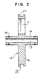
- Anti-telescoping plate 10 for example, as shown in Fig. 2, comprises disc portion 12 having feed water passages 11, and joint tube portion 14 provided in the central portion of the disc portion 12, which has permeated water passage 13 and on which a member 19 preventing feed water from entering into permeate collection tube 3 (feed water entering prevention member) such as an O-ring is attached.
- feed water entering prevention member such as an O-ring
- feed water entering prevention member 19 is attached for preventing feed water from entering into permeated water.
- the feed water entering prevention member 19 is attached at a position nearer the end of permeate collection tube 3 than the position of the end permeate collection opening 2 when anti-telescoping plate 10 is attached to fluid separation element 9, and thus, feed water from permeate collection openings 2 can be prevented from entering into permeated water.
- feed water entering prevention member 19 is preferably located at a position in the range of 20 to 90 mm from the end of permeate collection tube 3.
- Joint tube portion 14 is inserted into permeate collection tube 3 of fluid separation element 9. Therefore, the diameter of joint tube portion 14 is set to be smaller than the inner diameter of permeate collection tube 3 of fluid separation element 9, and in order to suppress the backlash when connected to the fluid separation element 9 small and improve the seal ability of feed water, the difference between the diameters is preferably in the range of 0.01 to 0.5 mm. Further, it is preferred that joint tube portion 14 projects from the side surface of anti-telescoping plate 10 by a length in the range of 25 to 100 mm. In order to ensure the permeated water passage sufficiently large and joint tube portion 14 sufficiently strong, the difference between the outer diameter and the inner diameter of the joint tube portion 14 is preferably in the range of 6 to 16 mm, more preferably in the range of 8 to 14 mm.
- Disc portion 12 of anti-telescoping plate 10 is preferably composed of a material having a high stiffness, which has a flexural strength of 50 MPa or more, in order to obtain a sufficiently large feed water passage 11 and the sufficiently great strength.
- a material having a high stiffness for example, a metal, a plastic and an FRP can be used, and in particular, a stainless steel which is hardly affected by a corrosion such as rust caused during use, polyphenylene oxide, polycarbonate, hard vinyl chloride, etc. are preferred.
- Disc portion 12 is preferred to be thin in order to lengthen fluid separation element 9 and enlarge the membrane area, but preferred to be thick in order to obtain a high strength.
- ribs 41 of anti-telescoping plate 10 are preferred to be thick in the circumferential direction of the anti-telescoping plate 10.
- the thickness of disc portion 12 of anti-telescoping plate 10 is preferably in the range of 5 to 35 mm.
- the shape of disc portion 12 may be greater than the size of the cross section of fluid separation element 9, and when assembled as a fluid separation membrane module, it may be a size capable of being contained in a pressure vessel.
- a plurality of the above-described fluid separation element assemblies are connected and contained in a pressure vessel to form a fluid separation membrane module.
- a fluid separation membrane module for example, as shown in Figs. 3 and 4, two fluid separation elements 9 adjacent to each other are connected via a single anti-telescoping plate 10. Therefore, because the space required for the connection is a space corresponding to the thickness of one anti-telescoping plate 10, as compared with a conventional fluid separation membrane module wherein an anti-telescoping plate is attached to each end of a fluid separation element and further another particular member for the connection is required, each fluid separation element 9 can be lengthened in the axial direction and a plurality of the long fluid separation elements can be contained in a conventional pressure vessel, namely, without change of the outer size, the effective membrane area in the module can be increased, and the amount of water to be treated per one fluid separation element can be increased.
- feed water 20 supplied into a pressure vessel passes through feed water passage 11 of anti-telescoping plate 10 and enters membrane unit 7 of fluid separation element 9. While feed water 20 fed into membrane unit 7 flows along feed carrier material 6 downstream, a part of the feed water is permeated through separation membrane 4 and unnecessary ingredients such as salt are removed, and permeated water 21 flows into permeate carrier material 5.
- the permeated water 21 flown into permeate carrier material 5 flows toward permeate collection tube 3 positioned at the central portion of fluid separation element 9. Permeated water 21 having reached permeate collection tube 3 enters into the tube 3 through permeate collection openings 2, and then flows therein in the downstream direction.
- the permeated water 21 in permeate collection tube 3 flows through the permeated water passage of a joint tube portion 14 of a next anti-telescoping plate 10 and enters a permeate collection tube 3 of a next fluid separation element 9.
- Feed water which has not been treated by one fluid separation element 9 goes forward to a next fluid separation element 9 through feed water passage 11 of anti-telescoping plate 10, and it is treated by the downstream side (next) fluid separation element 9.
- feed water may also flow through a gap between pressure vessel 15 and wrapping material 8 of fluid separation element 9.
- generation of micro-organism and decay of organic substances present in the feed water which are likely to be caused by the residence of the feed water in the gap, may be prevented.
- the amount of the flown feed water is too much, the amount of the feed water flowing along the separation membrane decreases, the concentration polarization on the surface of the separation membrane becomes great, and therefore, not only the amount of permeated water and the salt rejection percent decrease but also the amount of deposit on the surface of the separation membrane increases.
- the times of the treatment for producing purified water increases but also the time required for the treatment becomes long, and besides, the life of the separation membrane is shortened.
- feed water seal means is provided in order to prevent feed water from leaking from a gap between fluid separation element 9 and anti-telescoping plate 10 to a gap between pressure vessel 15 and wrapping material 8 of the fluid separation element 9. Further, a seal ring is provided on the periphery of anti-telescoping plate 10 free to be detached in order to prevent a large amount of feed water from flowing straightly through the portion of the periphery of the anti-telescoping plate 10 and leaking into a gap between pressure vessel 15 and a next fluid separation element 9.
- Feed water seal means for preventing feed water through a gap between fluid separation element 9 and anti-telescoping plate 10 may be constructed from a ring member provided on at least one end of wrapping material 8 and projecting in the axial direction of the fluid separation element 9.
- This ring member provided as feed water seal means may be formed as an axially projected ring portion 8a of wrapping material 8 itself, which axially projects from the axial end surface of membrane unit 7.
- a feed water seal member 26, formed separately from wrapping material 8 may be provided on the axial end portion of the wrapping material 8, and the feed water seal member 26 projecting axially from the end surface of membrane unit 7 may be brought into contact with anti-telescoping plate 10.
- feed water seal member 8a or 26 By such a feed water seal member 8a or 26, a large amount of feed water can be prevented from leaking into a gap between pressure vessel 15 and fluid separation element assembly 1 (or fluid separation element 9).
- the thickness of feed water seal member 8a or 26 is preferred to be in the range of 0.5 to 5 mm from the viewpoint of strength and membrane area, and from the viewpoint of sealing ability, the feed water seal member is preferred to be projected by an axial length in the range of 1 to 10 mm from the end surface of membrane unit 7.
- the feed water seal member 8a or 26 is preferably formed from a material having a high stiffness, for example, having a flexural strength of 50 MPa or more.
- a material having a high stiffness for example, a metal, a plastic and an FRP can be used, and in particular, a stainless steel which is hardly affected by a corrosion such as rust caused during use, polyphenylene oxide, polycarbonate, hard vinyl chloride, etc. are preferred.
- an FRP is used as a material of a wrapping material of a fluid separation element. In this case, the portion formed as the feed water seal member can be easily molded integrally with the FRP wrapping material by using an appropriate mold, and because a new member is not required, FRP is particularly preferred as the material of the feed water seal member.
- a relatively rough feed water seal member may be used, without decreasing the ability of the fluid separation element assembly such as the salt rejection property and the amount of water to be treated.
- a feed water seal member having a small flaw a feed water seal member having a notch of about 1 to 30 mm or a snap ring-like feed water seal member having a gap in the circumferential direction may be used.
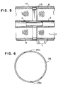
- a feed water seal member 26 formed as a divided ring having seams 26a at positions in the circumferential direction may be also used.
- seal ring 28 is preferably formed from a elastic material for bringing it into contact with the inner surface of pressure vessel 15.
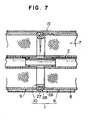
- a feed water seal member is provided on wrapping material 8 of fluid separation element 9 and a seal ring is provided on the periphery of anti-telescoping plate 10, for example, as shown in Fig. 7, an effective sealing can be achieved by bringing projected feed water seal member 26 provided to wrapping material 8 into contact with seal ring 28 provided to anti-telescoping plate 10.
- a seal ring 28a having a portion projecting toward the downstream side may be attached on the periphery of anti-telescoping plate 10, and the seal ring 28a may comes into contact with the axial end of the wrapping material or a feed water seal member provided on the end portion of the wrapping material, for effective sealing.
- a side wall located at a position downstream of groove 27 is formed to be lower than a side wall located at a position upstream of the groove 27.
- a ring portion 51 projecting toward fluid separation element 9 may be provided on a radially outer portion of anti-telescoping plate 50.
- Groove 27 similar to that shown in Fig. 4 is defined on the periphery of anti-telescoping plate 50, and seal ring 28 is fitted into the groove 27.
- anti-telescoping plate 50 can be easily fitted to fluid separation element 9 by utilizing projected ring portion 51, and the attachment and detachment thereof can be facilitated.
- the property for sealing feed water may be further improved by utilizing projected ring portion 51.
- feed water seal member 52 is provided between projected ring portion 51 and the periphery of wrapping material 8 of fluid separation element 9, and a short of feed water at this portion can be suppressed.
- feed water seal member 53 composed of a tape or an elastic material may be provided so that it covers an area extending from the periphery of projected ring portion 51 to the periphery of wrapping material 8 of fluid separation element 9, thereby suppressing a short of feed water at this portion similarly.
- a taller upstream side wall 61 and a lower downstream side wall 62 are provided on the periphery of anti-telescoping plate 60 so that they extend in the circumferential direction of the anti-telescoping plate 60, groove 27 is formed between both side walls 61 and 62, and seal ring 28 is fitted into the groove 27.
- seal ring 28 is fitted into the groove 27.
- wrapping material 8 of upstream side fluid separation element 9 is projected so that the tip thereof comes into contact with the side surface of upstream side wall 61, and the projected portion of wrapping material 8 of downstream side fluid separation element 9 or a feed water seal member 26 provided on the end portion of the wrapping material 8 is fitted around downstream side wall 62 and the tip thereof is brought into contact with the side surface of seal ring 28.
- the sealing ability of feed water may be adequately increased as well as the connection of upstream and downstream side fluid separation elements 9 and anti-telescoping plate 60 interposed therebetween may be facilitated.
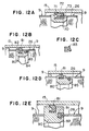
- Figs. 12A to 12E various structures as shown in Figs. 12A to 12E may be employed in order to suppress a short of feed water more appropriately.
- seal ring 72 provided in groove 71 formed on the periphery of anti-telescoping plate 70 is formed as a shape having a groove 73 on the downstream side surface, and the tip portion of projected feed water seal member 26 provided on the end portion of wrapping material 8 of downstream side fluid separation element 9 is inserted into the groove 73.
- groove 82 is formed on the periphery of anti-telescoping plate 80, seal ring 81 brought into contact with the inner surface of pressure vessel 15 is fitted into the groove 82, and on the downstream side thereof, a particular seal member 83 for preventing a short of feed water and a groove 84 fitted with the seal member 83 are provided.
- This seal member 83 is brought into contact with the inner surface of projected feed water seal member 26 provided on the end portion of wrapping material 8 of downstream side fluid separation element 9, and this portion is sealed.
- a member having a cross section as shown in Fig. 12C also can be used.
- O-ring 85 may be used instead of the seal member 83 having the above-described forms. Further, in accordance with the relationship between the position of the inner surface of pressure vessel 15 and the position of the outer surface of fluid separation element 9, for example, as shown in Fig.
- a ring-like groove 91 may be formed on the side surface of anti-telescoping plate 90 and a seal member 92 composed of, for example, an elastomer, may be fitted into the groove 91.
- Feed water seal member 26 provided on the end portion of wrapping material 8 of downstream side fluid separation element 9 may be brought into contact with the seal member 92.
- the sealing ability on the radially outer portion of the anti-telescoping plate may be further improved.
- a flat tip 26a as shown in Fig. 13A, a tip 26b formed with a round or a chamfer on one corner as shown in Fig. 13B, or a round tip 26c as shown in Fig. 13C, may be employed.
- both tubes may be connected by a screw structure.
- screws are defined on the periphery of joint tube portion 121 of anti-telescoping plate 120 and the inner surface of permeate collection tube 122, respectively, and both tubes are connected at a screw portion 123.
- the sealing ability between feed water seal member 26 provided on the end portion of wrapping material 8 and anti-telescoping plate 120 is increased, thereby preventing feed water from leaking into a gap between fluid separation element 9 and pressure vessel 15.
- the joint tube portion may be formed as a separate member.
- disc portion 131 and joint tube portion 132 of anti-telescoping plate 130 are formed as members separate from each other, and both members are assembled into the anti-telescoping plate 130.
- stepped portion 131a formed on the inner surface of disc portion 131 and stepped portion 132a formed on the periphery of joint tube portion 132 are engaged with each other in the axial direction receiving a thrust load to form anti-telescoping plate 130.
- a pressing member is provided between a lid of a pressure vessel and an anti-telescoping plate of a fluid separation element assembly located at a most upstream position, in order to sufficiently press a most upstream positioned anti-telescoping plate to the fluid separation element, thereby preventing feed water from leaking a gap between the pressure vessel and the fluid separation element through a gap between the anti-telescoping plate and the fluid separation element.
- a pressing member for example, as shown in Fig. 16, may be formed by a structure wherein an urging member such as a metal spring 17 is interposed between anti-telescoping plate 10 and lid 16 of pressure vessel 15.
- an adjusting bolt 18 may be provided to lid 16 of pressure vessel 15.
- feed carrier material 6 preferably has a high performance for making the flow of feed water turbulent in order to suppress the concentration polarization small.
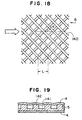
- a net having meshes each shaped as a rhombus is used in order to make the flow of feed water turbulent on the surface of the separation membrane.
- the net is preferably disposed so that the longer axis of the rhombus is directed in the flow direction of feed water, and the angle of a side of the rhombus is preferably in the range of ⁇ 15 to ⁇ 45 degrees relative to the flow direction of feed water.
- the "long axis” means a longer axis among the axes formed between the confronting corner points of a rhombic mesh
- the "angle of a side of the rhombus relative to the flow direction of feed water” means, as shown in Fig. 18, an angle ⁇ defined by the flow direction of feed water shown by an arrow and a mesh leg 140 forming the mesh. More preferably, the angle is in the range of ⁇ 15 to ⁇ 40 degrees. If this angle is smaller than 15 degrees, the turbulence performance for feed water rapidly decreases and the concentration near the surface of the separation membrane increases, and the concentration polarization becomes greater, the separation ability deteriorates and the quality of the treated water deteriorates.
- the angle of the mesh leg is in the range of ⁇ 20 to ⁇ 35 degrees relative to the flow direction of feed water.
- the thickness of the net is preferably 0.9 mm or less, more preferably 0.8 mm or less, in order to prevent a reduction of the area of the separation membrane and to obtain a sufficiently large amount of treated water.
- the thickness of the net is preferably 0.5 mm or more, more preferably 0.6 mm or more, in order to prevent remarkable increase of flow resistance and pressure loss due to a narrow passage.
- the length L of the longer axis of the rhombic mesh shown in Fig. 18 is preferably in the range of 3 to 8 mm. By setting this length 3 mm or more, the density of net intersections per unit area may be suppressed small to prevent increase of flow resistance, thereby preventing increase of pressure loss.
- the length L of the longer axis is more preferably in the range of 3.3 to 7 mm, further more preferably in the range of 3.5 to 6 mm.
- the material of the net is preferably a polypropylene, a polyethylene, a nylon, a polyester, etc.
- the resistance in the passage formed by permeate carrier material 5 is preferably suppressed as low as possible, in order to further increase the separation performance of the separation membrane.
- the opening ratio in the cross section of the carrier material is required to be great.
- the permeate carrier material is desired to be thinner in order to increase the charge density of the separation membrane in the membrane unit, this requirement is contrary to the requirement for decreasing the resistance of the passage, and in practice, the thickness of the permeate carrier material is designed to be an optimum value, from the viewpoint of the balance of the affections due to the respective requirements.
- permeate carrier material 5 is used in a condition where grooves 141 of the material 5 forming the permeated water passage are directed in a direction perpendicular to the axis of permeate collection tube 3.
- the thickness of permeate carrier material 5 is preferably in the range of 0.2 to 0.4 mm.
- projections 142 forming grooves 141 provided as the permeated water passage and supporting separation membrane 4 are formed on the surface of the permeate carrier material 5.
- wrapping material 8 The function required to wrapping material 8 is to maintain the formation of cylindrical fluid separation element 9. It is required to cover the entire periphery of membrane unit 7 with wrapping material 8 in order to flow feed water 20 uniformly on the surface of the separation membrane. Further, because fluid separation element 9 is structured to be applied with an inner pressure during use, it is required to prevent an easy expansion or breakage of the element 9. From such requirements, wrapping material 8 is typically formed by using a filament winding process, wherein a resin such as an epoxy is impregnated into glass fibers or polyester filaments, the resin impregnated material is wound around membrane unit 7, and thereafter, the resin is cured.
- a resin such as an epoxy
Landscapes
- Chemical & Material Sciences (AREA)
- Chemical Kinetics & Catalysis (AREA)
- Engineering & Computer Science (AREA)
- Analytical Chemistry (AREA)
- General Chemical & Material Sciences (AREA)
- Oil, Petroleum & Natural Gas (AREA)
- Separation Using Semi-Permeable Membranes (AREA)
Description
- The present invention relates to a fluid separation element assembly, and more specifically to a fluid separation element assembly suitable for use in an apparatus for reverse osmosis, ultrafiltration or microfiltration.
- Generally, a spiral type fluid separation element assembly is formed, for example, as shown in Fig. 20. In Fig. 20, a
permeate carrier material 156 is disposed between afirst separation membrane 154 and asecond separation membrane 155, thefirst separation membrane 154 andsecond separation membrane 155 are closed at three sides by, for example, an adhesive, and the remaining one side is opened in a direction toward apermeate collection tube 153 havingpermeate collection openings 152 to form an envelope member. Amembrane unit 160 including this envelope member and afeed carrier material 157 is spirally wound around thepermeate collection tube 153. Ananti-telescoping plate 158 is attached on the downstream-side end surface of thewound membrane unit 160, aseal holder 159 is attached on the upstream-side end surface thereof, and awrapping material 161 is formed on the periphery of themembrane unit 160. As theseal holder 159, generally the same plate as theanti-telescoping plate 158 is used. - In such a fluid
separation element assembly 151, feed water having entered from the side ofseal holder 159 through afeed water passage 162 is separated towater 164a permeated throughseparation membranes remaining feed water 164b during being passed throughfeed carrier material 157. The permeatedwater 164a is discharged from the exit ofpermeate collection tube 153, and theremaining feed water 164b (concentrated water) is discharged from the exit ofanti-telescoping plate 158, respectively.Anti-telescoping plate 158 prevents a telescoping deformation offluid separation element 151 due to a pressure loss caused whenfeed water 163 passes throughfeed carrier material 157.Anti-telescoping plate 158 andseal holder 159 are integrally combined withmembrane unit 160 so that they are not easily decomposed by a load originating from the pressure loss. Therefore, whenfluid separation element 151 has fallen in a condition that it cannot be used, for example, by reduction of the performance of the separation membrane, the members such asanti-telescoping plate 158 andpermeate collection tube 153 are discarded without being reused, in spite of a condition that they are still usable. - On the other hand, a fluid separation element assembly having a anti-telescoping plate is disclosed in U.S. Patent 4,906,372. In the fluid separation element assembly, as shown in Fig. 21, because there is no means for preventing feed water from leaking toward the periphery side of a
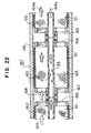
fluid separation element 151 from a gap between thefluid separation element 151 and ananti-telescoping plate 158 attached on the upstream-side end surface of thefluid separation element 151, anet member 165 is provided on the periphery of thefluid separation element 151. - In the fluid separation using such a fluid separation element assembly, as shown in Fig. 22,
fluid separation element 151 is contained in apressure vessel 166 to be used as a fluidseparation membrane module 167.Net member 165 attached on the periphery offluid separation element 151 is also contained, and the gap betweenpressure vessel 166 andfluid separation element 151 may be sealed. In this case, althoughnet member 165 has an elasticity, in order that thenet member 165 is shrunk when it is inserted intopressure vessel 166, it is necessary to well finish the accuracy of the diameter offluid separation element 151 and the thickness of thenet member 165 depending upon the accuracy of the inner diameter of thepressure vessel 166. - In practice, however,
fluid separation element 151 has a dispersion in its diameter more or less, depending upon a dispersion of the thickness of the member(s) used for thefluid separation element 151. Because relatively many kinds of the members are used forfluid separation element 151 and a relatively large amount of them is used therefor, for example, in an 8 inch fluid separation element, there occurs a dispersion in the thickness of the diameter of the fluid separation element of 2 to 3 mm. When the diameter offluid separation element 151 includingnet member 165 is smaller than the inner diameter ofpressure vessel 166, thenet member 165 does not comes into contact with thepressure vessel 166, and because the gap between thepressure vessel 166 and thefluid separation element 151 cannot be sealed, a relatively large amount offeed water 163 passes through the gap between thepressure vessel 166 and thefluid separation element 151. As a result, the amount offeed water 163 passing along the surface of the separation membrane decreases, the concentration polarization on the surfaces ofseparation membranes water 164a decreases as well as the salt rejection performance in the membrane separation is greatly reduced. Particularly, in a process such as desalting of sea water in which the feed water has a high salt concentration, the affection due to the concentration polarization is great, the quality of the permeatedwater 164a is remarkably reduced. - It may be possible to increase the property of the shrinkage of
net member 165 by setting the diameter of the portion ofmembrane unit 160 fairly smaller than the inner diameter ofpressure vessel 166 in consideration of the dispersion of the diameter offluid separation element 151, and by making thenet member 165 thick. In this case, however, because it is necessary to form the portion ofmembrane unit 160 offluid separation element 151 small, the effective membrane area becomes small, and the amount of water treated by thefluid separation element 151 may be decreased. - It would be desirable to provide a fluid separation element assembly which enables reuse of members, and which can appropriately prevent leakage of feed water and ensure a large effective membrane area.
- Further, it would be desirable to provide a fluid separation membrane module using such a fluid separation element assembly, which can achieve an excellent performance.
- A fluid separation element assembly according to the present invention comprises a fluid separation element having a membrane unit and a wrapping material formed around said membrane unit, the membrane unit being formed by a separation membrane, a permeate carrier material and a feed carrier material which are spirally wound around a permeate collection tube; an anti-telescoping plate attached to at least one end of the fluid separation element at a condition free to be detached; and feed water seal means for preventing feed water from leaking through a gap between the fluid separation element and the anti-telescoping plate.
- The feed water seal means, for example, comprises a ring member provided on at least one end of the wrapping material and projecting in the axial direction of the fluid separation element.
- The ring member is preferably composed of a material having a flexural strength of 50 MPa or more. The ring member may be formed as either a ring formed integrally over the entire circumference or a divided ring having seams at positions in the circumferential direction of the ring member. The ring member preferably comes into contact with the anti-telescoping plate.
- A seal ring, which is a member different from the feed water seal means, may be attached on a periphery of the anti-telescoping plate. The seal ring is preferably attached in a groove formed on the periphery of the anti-telescoping plate. In this case, a side wall located at a position upstream of the groove in the flow direction of the feed water may be taller than a side wall located at a position downstream of the groove in the flow direction of the feed water, and the seal ring attached in the groove may come into contact with the fluid separation element. In particular, the seal ring attached in the groove may come into contact with the ring member provided on the wrapping material.
- The feed water seal means may be constituted as another formation. For example, a ring portion projecting toward a fluid separation element side is provided on a radially outer portion of the anti-telescoping plate. In this embodiment, the feed water seal means is provided between the projected ring portion and a periphery of the fluid separation element, or the feed water seal means covers an area extending from a periphery of the projected ring portion to a periphery of the fluid separation element.
- Also in such a structure, a seal ring may be attached on a periphery of the anti-telescoping plate. The seal ring is preferably attached in a groove formed on the periphery of the anti-telescoping plate.
- The anti-telescoping plate, for example, comprises a disc portion having a feed water passage and a joint tube portion provided in a central portion of the disc portion and having a permeated water passage. Preferably, the anti-telescoping plate further comprises a member preventing feed water from entering into the permeate collection tube. The disc portion and the joint tube portion either may be integrally formed, or may be formed separately from each other. The joint tube portion is preferably inserted into the permeate collection tube.
- The feed carrier material, for example, comprises a net. Preferably, the net has meshes each shaped as a rhombus, the net is disposed so that a longer axis of the rhombus is directed in the flow direction of the feed water, the angle of a side of the rhombus is in a range of ± 15 to ± 45 degrees relative to the flow direction of the feed water, the thickness of the net is in a range of 0.5 to 0.9 mm, and the length of the longer axis of the rhombus is in a range of 3 to 8 mm.
- Further, another embodiment of the fluid separation element assembly according to the present invention comprises a fluid separation element having a membrane unit and a wrapping material formed around the membrane unit, the membrane unit being formed by a separation membrane, a permeate carrier material and a feed carrier material which are spirally wound around a permeate collection tube; an anti-telescoping plate attached to at least one end of the fluid separation element at a condition free to be detached; and a seal ring attached on a periphery of the anti-telescoping plate for sealing a gap between the periphery of the anti-telescoping plate and an inner surface of a pressure vessel containing the fluid separation element and the anti-telescoping plate.
- In this fluid separation element assembly, preferably the seal ring is attached in a groove formed on the periphery of the anti-telescoping plate. In this case, a side wall located at a position upstream of the groove in the flow direction of feed water may be taller than a side wall located at a position downstream of the groove in the flow direction of the feed water, and the seal ring attached in the groove may come into contact with the fluid separation element.
- A fluid separation membrane module according to the present invention may be constructed by containing a plurality of the above-described fluid separation element assemblies in a pressure vessel. In the module, preferably the pressure vessel has a lid at its each axial end, and between the lid and an anti-telescoping plate of a fluid separation element assembly located at a most upstream position in the flow direction of feed water, means for pressing the anti-telescoping plate in the axial direction of the pressure vessel is provided.
- In the fluid separation element assembly according to the present invention, because the anti-telescoping plate is attached to the fluid separation element at a condition free to be detached, even when the fluid separation element assembly has fallen in a unusable condition (for example, when the separation membrane has reached its life), it may be possible to discard only the members having defects and to reuse other members, for example, the anti-telescoping plate and seal members, and as the case may be, the permeate collection tube. In such a fluid separation element assembly having a detachable anti-telescoping plate, by providing the feed water seal means for preventing the leakage of feed water through a gap between the fluid separation element and the anti-telescoping plate, a large amount of feed water can be prevented from passing through a gap between the pressure vessel and the fluid separation element assembly. As a result, the concentration polarization on the surface of the separation membrane may be suppressed small, and a fluid separation element assembly having a high separation performance can be realized.
- Further, in the fluid separation element assembly having a detachable anti-telescoping plate, by providing the seal ring capable of sealing a gap between the periphery of the anti-telescoping plate and the inner surface of the pressure vessel, the leakage of feed water through the gap between the pressure vessel and the fluid separation element can be appropriately suppressed at a position of the anti-telescoping plate, without consideration of a dispersion of the diameter of the fluid separation element. Therefore, a large amount of feed water passing on the surface of the separation membrane of the fluid separation element can be ensured, the concentration polarization on the separation membrane may be maintained small, a large amount of permeated water can be ensured, and a good property for salt rejection in the membrane separation can be ensured. Moreover, it may be possible to enlarge the diameter of the fluid separation element, and with respect to the radial direction, the effective membrane area may be increased. As a result, the amount of the treatment may be greatly increased and the quality of the treated water may be greatly improved.
- In the assembly of the fluid separation membrane module using the fluid separation element assemblies according to the present invention, it is possible to connect the fluid separation elements to each other by an anti-telescoping plate itself by providing a joint tube portion to the anti-telescoping plate. In such a fluid separation membrane module, for example, as compared with a conventional module wherein an anti-telescoping plate is combined integrally with a fluid separation element and a relatively large space is required for connecting the fluid separation element assemblies to each other, a space required for the connection can be greatly decreased. Therefore, in a fluid separation membrane module connecting a plurality of fluid separation elements, it is possible to increase the effective length of each fluid separation element in the module, and with respect to the axial direction of the fluid separation element, the effective membrane area can be increased, thereby increasing the ability of the treatment greatly. Moreover, in the fluid separation membrane module using the fluid separation element assemblies according to the present invention, because basically it is not necessary to change structural members such as the pressure vessel, the cost for manufacture may be suppressed low.
- Further objects, features, and advantages of the present invention will be understood from the following detailed description of the preferred embodiments of the present invention with reference to the accompanying figures.
- Preferred embodiments of the invention are now described with reference to the accompanying figures, which are given by way of example only, and are not intended to limit the present invention.
- Fig. 1 is a perspective view of a fluid separation element assembly according to an embodiment of the present invention.
- Fig. 2 is an enlarged vertical sectional view of an anti-telescoping plate of the fluid separation element assembly shown in Fig. 1.
- Fig. 3 is a vertical sectional view of a fluid separation membrane module according to an embodiment of the present invention.
- Fig. 4 is a partial vertical sectional view of a fluid separation membrane module showing a structure of feed water seal means according to an embodiment of the present invention.
- Fig. 5 is a partial vertical sectional view of a fluid separation membrane module showing a structure of feed water seal means according to another embodiment of the present invention.
- Fig. 6 is an elevational view showing an example of the structure of a feed water seal member according to an embodiment of the present invention.
- Fig. 7 is a partial vertical sectional view of a fluid separation membrane module showing a structure of feed water seal means according to a further embodiment of the present invention.
- Fig. 8 is a partial vertical sectional view of a fluid separation membrane module showing a structure of feed water seal means according to a still further embodiment of the present invention.
- Fig. 9 is a partial vertical sectional view of a fluid separation membrane module according to a still further embodiment of the present invention.
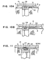
- Figs. 10A and 10B are partial vertical sectional views of fluid separation membrane modules showing structures of feed water seal means according to still further embodiments of the present invention.
- Fig. 11 is a partial vertical sectional view of a fluid separation membrane module showing a structure of feed water seal means according to a still further embodiment of the present invention.
- Figs. 12A-12E are partial vertical sectional views of fluid separation membrane modules showing structures of various type seal members according to still further embodiments of the present invention.
- Figs. 13A-13C are partial vertical sectional views of fluid separation elements showing structures of feed water seal members according to still further embodiments of the present invention.
- Fig. 14 is a partial vertical sectional view of a fluid separation membrane module showing a connection structure of an anti-telescoping plate and a permeate collection tube according to a still further embodiment of the present invention.
- Fig. 15 is a partial vertical sectional view of a fluid separation membrane module showing a structure of an anti-telescoping plate according to a still further embodiment of the present invention.
- Fig. 16 is a partial vertical sectional view of a fluid separation membrane module showing a structure of the end portion of the module according to a still further embodiment of the present invention.
- Fig. 17 is a partial vertical sectional view of a fluid separation membrane module showing another structure of the end portion of the module according to a still further embodiment of the present invention.
- Fig. 18 is a partial plan view of a feed carrier material according to an embodiment of the present invention.
- Fig. 19 is a partial sectional view of a permeate carrier material according to an embodiment of the present invention.
- Fig. 20 is a perspective view of a conventional fluid separation element assembly.
- Fig. 21 is a perspective view of another conventional fluid separation element assembly.
- Fig. 22 is a partial vertical sectional view of a fluid separation membrane module using the fluid separation element assemblies shown in Fig. 21.
- Fig. 1 shows a fluid separation element assembly according to an embodiment of the present invention. In fluid
separation element assembly 1 shown in Fig. 1,membrane unit 7 includingseparation membrane 4,permeate carrier material 5 andfeed carrier material 6 is spirally wound aroundpermeate collection tube 3 havingpermeate collection openings 2, and wrappingmaterial 8 is formed on the periphery of themembrane unit 7 to form afluid separation element 9. The axial end surfaces offluid separation element 9 are exposed, and ananti-telescoping plate 10 is attached to at least one end of thefluid separation element 9 in order to prevent a telescoping deformation of thefluid separation element 9.Anti-telescoping plate 10 is attached to the end offluid separation element 9 free to be detached so that thefluid separation element 9 and theanti-telescoping plate 10 can be exchanged as needed. If an anti-telescoping plate is fixed in a fluid separation element assembly at a condition that the anti-telescoping plate cannot be easily detached, when the assembly has fallen in a condition where the fluid separation cannot be sufficiently performed by, for example, reduction of the ability of the separation membrane, the whole of the fluid separation element assembly must be discarded. Even in such a case, in fluidseparation element assembly 1 according to the present invention, becauseanti-telescoping plate 10 is detachably provided, it is possible to exchangeonly membrane unit 7 and reuseanti-telescoping plate 10 and, in addition, permeatecollection tube 3 as the case may be. -
Anti-telescoping plate 10 according to the present invention, for example, as shown in Fig. 2, comprisesdisc portion 12 having feed water passages 11, andjoint tube portion 14 provided in the central portion of thedisc portion 12, which has permeatedwater passage 13 and on which amember 19 preventing feed water from entering into permeate collection tube 3 (feed water entering prevention member) such as an O-ring is attached. Becauseanti-telescoping plate 10 has not only feed water passages 11 and permeatedwater passage 13 but alsojoint tube portion 14, a particular connecting member, which has been required in a conventional device when a plurality of fluid separation element assemblies are connected in series, is not required. As a result, the space for connection is saved, and when the assemblies are contained in a pressure vessel to use as a fluid separation membrane module, the portion of the fluid separation element can be formed to be long, thereby improving the ability and efficiency. - On the
joint tube portion 14, feed water enteringprevention member 19 is attached for preventing feed water from entering into permeated water. The feed water enteringprevention member 19 is attached at a position nearer the end ofpermeate collection tube 3 than the position of the endpermeate collection opening 2 whenanti-telescoping plate 10 is attached tofluid separation element 9, and thus, feed water frompermeate collection openings 2 can be prevented from entering into permeated water. Moreover, by setting the distance between feed water enteringprevention member 19 andanti-telescoping plate 10 longer than the distance between theanti-telescoping plate 10 present at the most upstream position and a lid of a pressure vessel, feed water can be prevented from entering intopermeate collection tube 3 even if theanti-telescoping plate 10 orfluid separation element 9 moves in the pressure vessel during use. From the viewpoint of these matters, in case of a fluid separation element having a general length of 1016 mm, feed water enteringprevention member 19 is preferably located at a position in the range of 20 to 90 mm from the end ofpermeate collection tube 3. -
Joint tube portion 14 is inserted intopermeate collection tube 3 offluid separation element 9. Therefore, the diameter ofjoint tube portion 14 is set to be smaller than the inner diameter ofpermeate collection tube 3 offluid separation element 9, and in order to suppress the backlash when connected to thefluid separation element 9 small and improve the seal ability of feed water, the difference between the diameters is preferably in the range of 0.01 to 0.5 mm. Further, it is preferred thatjoint tube portion 14 projects from the side surface ofanti-telescoping plate 10 by a length in the range of 25 to 100 mm. In order to ensure the permeated water passage sufficiently large andjoint tube portion 14 sufficiently strong, the difference between the outer diameter and the inner diameter of thejoint tube portion 14 is preferably in the range of 6 to 16 mm, more preferably in the range of 8 to 14 mm. -
Disc portion 12 ofanti-telescoping plate 10 is preferably composed of a material having a high stiffness, which has a flexural strength of 50 MPa or more, in order to obtain a sufficiently large feed water passage 11 and the sufficiently great strength. As such a material having a high stiffness, for example, a metal, a plastic and an FRP can be used, and in particular, a stainless steel which is hardly affected by a corrosion such as rust caused during use, polyphenylene oxide, polycarbonate, hard vinyl chloride, etc. are preferred.Disc portion 12 is preferred to be thin in order to lengthenfluid separation element 9 and enlarge the membrane area, but preferred to be thick in order to obtain a high strength. To increase the strength,ribs 41 ofanti-telescoping plate 10 are preferred to be thick in the circumferential direction of theanti-telescoping plate 10. In consideration of these matters, when the above-described materials are used, the thickness ofdisc portion 12 ofanti-telescoping plate 10 is preferably in the range of 5 to 35 mm. The shape ofdisc portion 12 may be greater than the size of the cross section offluid separation element 9, and when assembled as a fluid separation membrane module, it may be a size capable of being contained in a pressure vessel. - For fluid separation, a plurality of the above-described fluid separation element assemblies are connected and contained in a pressure vessel to form a fluid separation membrane module.
- In a fluid separation membrane module according to the present invention, for example, as shown in Figs. 3 and 4, two
fluid separation elements 9 adjacent to each other are connected via a singleanti-telescoping plate 10. Therefore, because the space required for the connection is a space corresponding to the thickness of oneanti-telescoping plate 10, as compared with a conventional fluid separation membrane module wherein an anti-telescoping plate is attached to each end of a fluid separation element and further another particular member for the connection is required, eachfluid separation element 9 can be lengthened in the axial direction and a plurality of the long fluid separation elements can be contained in a conventional pressure vessel, namely, without change of the outer size, the effective membrane area in the module can be increased, and the amount of water to be treated per one fluid separation element can be increased. On the other hand, when the same amount of water to be treated as that of the conventional module is ensured, because the operation pressure for the treatment can be reduced, the cost for the treatment can be reduced. When a new plant is built, not only the numbers of pipes, pressure vessels, etc. can be decreased but also a low pressure pump can be employed and the pressure resistance of the pipes and the pressure vessels can be designed to be low, and the initial cost may be greatly decreased. - In the fluid separation using such a fluid
separation membrane module 40, as shown in Fig. 1, feedwater 20 supplied into a pressure vessel passes through feed water passage 11 ofanti-telescoping plate 10 and entersmembrane unit 7 offluid separation element 9. Whilefeed water 20 fed intomembrane unit 7 flows alongfeed carrier material 6 downstream, a part of the feed water is permeated throughseparation membrane 4 and unnecessary ingredients such as salt are removed, and permeatedwater 21 flows intopermeate carrier material 5. The permeatedwater 21 flown intopermeate carrier material 5 flows towardpermeate collection tube 3 positioned at the central portion offluid separation element 9. Permeatedwater 21 having reachedpermeate collection tube 3 enters into thetube 3 throughpermeate collection openings 2, and then flows therein in the downstream direction. The permeatedwater 21 inpermeate collection tube 3 flows through the permeated water passage of ajoint tube portion 14 of a nextanti-telescoping plate 10 and enters apermeate collection tube 3 of a nextfluid separation element 9. Feed water which has not been treated by one fluid separation element 9 (concentrated water) goes forward to a nextfluid separation element 9 through feed water passage 11 ofanti-telescoping plate 10, and it is treated by the downstream side (next)fluid separation element 9. - In such a flow condition, feed water may also flow through a gap between
pressure vessel 15 and wrappingmaterial 8 offluid separation element 9. By the flow of the feed water through the gap betweenpressure vessel 15 andfluid separation element 9, generation of micro-organism and decay of organic substances present in the feed water, which are likely to be caused by the residence of the feed water in the gap, may be prevented. However, if the amount of the flown feed water is too much, the amount of the feed water flowing along the separation membrane decreases, the concentration polarization on the surface of the separation membrane becomes great, and therefore, not only the amount of permeated water and the salt rejection percent decrease but also the amount of deposit on the surface of the separation membrane increases. As a result, not only the times of the treatment for producing purified water increases but also the time required for the treatment becomes long, and besides, the life of the separation membrane is shortened. - In the present invention, feed water seal means is provided in order to prevent feed water from leaking from a gap between
fluid separation element 9 andanti-telescoping plate 10 to a gap betweenpressure vessel 15 and wrappingmaterial 8 of thefluid separation element 9. Further, a seal ring is provided on the periphery ofanti-telescoping plate 10 free to be detached in order to prevent a large amount of feed water from flowing straightly through the portion of the periphery of theanti-telescoping plate 10 and leaking into a gap betweenpressure vessel 15 and a nextfluid separation element 9. - Feed water seal means for preventing feed water through a gap between
fluid separation element 9 andanti-telescoping plate 10 may be constructed from a ring member provided on at least one end of wrappingmaterial 8 and projecting in the axial direction of thefluid separation element 9. This ring member provided as feed water seal means, for example, as shown in Fig. 4, may be formed as an axially projected ring portion 8a of wrappingmaterial 8 itself, which axially projects from the axial end surface ofmembrane unit 7. Alternatively, as shown in Fig. 5, a feedwater seal member 26, formed separately from wrappingmaterial 8, may be provided on the axial end portion of the wrappingmaterial 8, and the feedwater seal member 26 projecting axially from the end surface ofmembrane unit 7 may be brought into contact withanti-telescoping plate 10. By such a feedwater seal member 8a or 26, a large amount of feed water can be prevented from leaking into a gap betweenpressure vessel 15 and fluid separation element assembly 1 (or fluid separation element 9). The thickness of feedwater seal member 8a or 26 is preferred to be in the range of 0.5 to 5 mm from the viewpoint of strength and membrane area, and from the viewpoint of sealing ability, the feed water seal member is preferred to be projected by an axial length in the range of 1 to 10 mm from the end surface ofmembrane unit 7. When a pressure loss influid separation element 9 is relatively high, because a force is applied to feedwater seal member 8a or 26 to deform theseal member 8a or 26 from the inside to the outside of thefluid separation element 9, the feedwater seal member 8a or 26 is preferably formed from a material having a high stiffness, for example, having a flexural strength of 50 MPa or more. As such a material having a high stiffness, for example, a metal, a plastic and an FRP can be used, and in particular, a stainless steel which is hardly affected by a corrosion such as rust caused during use, polyphenylene oxide, polycarbonate, hard vinyl chloride, etc. are preferred. Generally, an FRP is used as a material of a wrapping material of a fluid separation element. In this case, the portion formed as the feed water seal member can be easily molded integrally with the FRP wrapping material by using an appropriate mold, and because a new member is not required, FRP is particularly preferred as the material of the feed water seal member. - When the concentration of feed water is relatively low such as a case of desalting of brackish water, because the concentration polarization on the surface of the separation membrane hardly increases even if feed water leaks from a seal portion, a relatively rough feed water seal member may be used, without decreasing the ability of the fluid separation element assembly such as the salt rejection property and the amount of water to be treated. For example, a feed water seal member having a small flaw, a feed water seal member having a notch of about 1 to 30 mm or a snap ring-like feed water seal member having a gap in the circumferential direction may be used. Alternatively, as shown in Fig. 6, a feed
water seal member 26 formed as a dividedring having seams 26a at positions in the circumferential direction may be also used. For example, in case of using an 8 inch fluid separation element assembly, if feed water can flow in the fluid separation element assembly at a flow rate of 30 x 10 -3 m3/min. or more as the flow rate at its exit, fluid separation can be performed without affection due to the leakage of feed water from a gap. - In a case where a seal ring is provided on the periphery of
anti-telescoping plate 10, as shown in Fig. 4, it is preferred that agroove 27 is defined on the periphery ofanti-telescoping plate 10 for fixingseal ring 28 and theseal ring 28 is fitted into thegroove 27. In this case,seal ring 28 is preferably formed from a elastic material for bringing it into contact with the inner surface ofpressure vessel 15. - When a feed water seal member is provided on wrapping
material 8 offluid separation element 9 and a seal ring is provided on the periphery ofanti-telescoping plate 10, for example, as shown in Fig. 7, an effective sealing can be achieved by bringing projected feedwater seal member 26 provided to wrappingmaterial 8 into contact withseal ring 28 provided toanti-telescoping plate 10. Further, as shown in Fig. 8, aseal ring 28a having a portion projecting toward the downstream side may be attached on the periphery ofanti-telescoping plate 10, and theseal ring 28a may comes into contact with the axial end of the wrapping material or a feed water seal member provided on the end portion of the wrapping material, for effective sealing. In such cases, it is preferred that a side wall located at a position downstream ofgroove 27 is formed to be lower than a side wall located at a position upstream of thegroove 27. - Generally, in fluid separation using a fluid separation membrane module, there occurs a pressure loss as feed water flows in a fluid separation element assembly in the downstream direction, and there is a case where the fluid separation element assembly is deformed in a telescoping form by a thrust load caused by the pressure loss and the deformed assembly is pushed onto the downstream side. When there occurs a pressure loss of 5 x 10⁵ Pa in an 8 inch fluid separation element assembly, the thrust load applied to the axial end surface of the fluid separation element assembly reaches 1.5 x 10⁴ N. However, in the fluid separation membrane module according to the present invention, because there is an anti-telescoping plate between adjacent fluid separation elements, such a deformation can be prevented. In the prevention of the deformation, because projected feed
water seal member 26 provided on wrappingmaterial 8 compressesseal ring 28 provided onanti-telescoping plate 10, it is preferred that an excessive compression load can be received bypermeate collection tube 3 which comes into contact with theanti-telescoping plate 10. - To an anti-telescoping plate located at the upstream portion of the most upstream side fluid separation element assembly in the pressure vessel, only a thrust load due to the pressure difference between a driving pressure at an entrance of
permeate collection tube 3 and a pressure of permeated water is applied, and therefore, a sufficiently large thrust load cannot be obtained. In such a case, preferably means for pressing the anti-telescoping plate in the axial direction of the pressure vessel is provided, as described later. By providing such means, it becomes possible to push the seal ring provided on the anti-telescoping plate to the feed water seal member provided on the end of the fluid separation element with a sufficiently large force, thereby sealing feed water at this portion. The pushing force may be about 250 N in an 8 inch fluid separation element assembly, and about 70 N in a 4 inch fluid separation element assembly. - In the present invention, the following various embodiments may be employed except the above-described embodiments.
- For example, as shown in Fig. 9, a
ring portion 51 projecting towardfluid separation element 9 may be provided on a radially outer portion ofanti-telescoping plate 50.Groove 27 similar to that shown in Fig. 4 is defined on the periphery ofanti-telescoping plate 50, andseal ring 28 is fitted into thegroove 27. In such a structure,anti-telescoping plate 50 can be easily fitted tofluid separation element 9 by utilizing projectedring portion 51, and the attachment and detachment thereof can be facilitated. - Moreover, the property for sealing feed water may be further improved by utilizing projected
ring portion 51. For example, as shown in Fig. 10A, feedwater seal member 52 is provided between projectedring portion 51 and the periphery of wrappingmaterial 8 offluid separation element 9, and a short of feed water at this portion can be suppressed. Further, as shown in Fig. 10B, feedwater seal member 53 composed of a tape or an elastic material may be provided so that it covers an area extending from the periphery of projectedring portion 51 to the periphery of wrappingmaterial 8 offluid separation element 9, thereby suppressing a short of feed water at this portion similarly. - With respect to a structure wherein
groove 27 is provided on the periphery of an anti-telescoping plate andseal ring 28 is provided in thegroove 27, for example, another structure as shown in Fig. 11 may be employed except the structures shown in Figs. 4 and 7. In Fig. 11, a tallerupstream side wall 61 and a lower downstream side wall 62 are provided on the periphery ofanti-telescoping plate 60 so that they extend in the circumferential direction of theanti-telescoping plate 60,groove 27 is formed between bothside walls 61 and 62, andseal ring 28 is fitted into thegroove 27. There provided an appropriate distance between eachside wall 61 or 62 and each corresponding side surface ofanti-telescoping plate 60. In this embodiment, wrappingmaterial 8 of upstream sidefluid separation element 9 is projected so that the tip thereof comes into contact with the side surface ofupstream side wall 61, and the projected portion of wrappingmaterial 8 of downstream sidefluid separation element 9 or a feedwater seal member 26 provided on the end portion of the wrappingmaterial 8 is fitted around downstream side wall 62 and the tip thereof is brought into contact with the side surface ofseal ring 28. In such a structure, the sealing ability of feed water may be adequately increased as well as the connection of upstream and downstream sidefluid separation elements 9 andanti-telescoping plate 60 interposed therebetween may be facilitated. - Further, in the present invention, various structures as shown in Figs. 12A to 12E may be employed in order to suppress a short of feed water more appropriately.
- In a structure shown in Fig. 12A,
seal ring 72 provided ingroove 71 formed on the periphery ofanti-telescoping plate 70 is formed as a shape having agroove 73 on the downstream side surface, and the tip portion of projected feedwater seal member 26 provided on the end portion of wrappingmaterial 8 of downstream sidefluid separation element 9 is inserted into thegroove 73. In a structure shown in Fig. 12B,groove 82 is formed on the periphery ofanti-telescoping plate 80,seal ring 81 brought into contact with the inner surface ofpressure vessel 15 is fitted into thegroove 82, and on the downstream side thereof, aparticular seal member 83 for preventing a short of feed water and agroove 84 fitted with theseal member 83 are provided. Thisseal member 83 is brought into contact with the inner surface of projected feedwater seal member 26 provided on the end portion of wrappingmaterial 8 of downstream sidefluid separation element 9, and this portion is sealed. As theseal member 83, for example, a member having a cross section as shown in Fig. 12C also can be used. Further, as shown in Fig. 12D, O-ring 85 may be used instead of theseal member 83 having the above-described forms. Further, in accordance with the relationship between the position of the inner surface ofpressure vessel 15 and the position of the outer surface offluid separation element 9, for example, as shown in Fig. 12E, a ring-like groove 91 may be formed on the side surface ofanti-telescoping plate 90 and aseal member 92 composed of, for example, an elastomer, may be fitted into thegroove 91. Feedwater seal member 26 provided on the end portion of wrappingmaterial 8 of downstream sidefluid separation element 9 may be brought into contact with theseal member 92. In such structures, the sealing ability on the radially outer portion of the anti-telescoping plate may be further improved. - As the shape of the tip of feed
water seal member 26 provided on the end portion of wrappingmaterial 8 offluid separation element 9, various shapes may be employed. For example, aflat tip 26a as shown in Fig. 13A, a tip 26b formed with a round or a chamfer on one corner as shown in Fig. 13B, or a round tip 26c as shown in Fig. 13C, may be employed. - Although
joint tube portion 14 ofanti-telescoping plate 10 is inserted intopermeate collection tube 3 ofmembrane unit 7 as aforementioned, both tubes may be connected by a screw structure. For example, as shown in Fig. 14, screws are defined on the periphery ofjoint tube portion 121 ofanti-telescoping plate 120 and the inner surface ofpermeate collection tube 122, respectively, and both tubes are connected at ascrew portion 123. In this structure, by the screw connection, the sealing ability between feedwater seal member 26 provided on the end portion of wrappingmaterial 8 andanti-telescoping plate 120 is increased, thereby preventing feed water from leaking into a gap betweenfluid separation element 9 andpressure vessel 15. - Although the above-described embodiments show an anti-telescoping plate integrally formed including a joint tube portion, the joint tube portion may be formed as a separate member. For example, as shown in Fig. 15,
disc portion 131 andjoint tube portion 132 ofanti-telescoping plate 130 are formed as members separate from each other, and both members are assembled into theanti-telescoping plate 130. In this structure, stepped portion 131a formed on the inner surface ofdisc portion 131 and steppedportion 132a formed on the periphery ofjoint tube portion 132 are engaged with each other in the axial direction receiving a thrust load to formanti-telescoping plate 130. - In the fluid separation membrane module according to the present invention, preferably a pressing member is provided between a lid of a pressure vessel and an anti-telescoping plate of a fluid separation element assembly located at a most upstream position, in order to sufficiently press a most upstream positioned anti-telescoping plate to the fluid separation element, thereby preventing feed water from leaking a gap between the pressure vessel and the fluid separation element through a gap between the anti-telescoping plate and the fluid separation element. Such a pressing member, for example, as shown in Fig. 16, may be formed by a structure wherein an urging member such as a
metal spring 17 is interposed betweenanti-telescoping plate 10 andlid 16 ofpressure vessel 15. Alternatively, as shown in Fig. 17, an adjustingbolt 18 may be provided tolid 16 ofpressure vessel 15. - In the fluid separation element assembly according to the present invention, feed
carrier material 6 preferably has a high performance for making the flow of feed water turbulent in order to suppress the concentration polarization small. Preferably a net having meshes each shaped as a rhombus is used in order to make the flow of feed water turbulent on the surface of the separation membrane. The net is preferably disposed so that the longer axis of the rhombus is directed in the flow direction of feed water, and the angle of a side of the rhombus is preferably in the range of ± 15 to ± 45 degrees relative to the flow direction of feed water. In the present invention, the "long axis" means a longer axis among the axes formed between the confronting corner points of a rhombic mesh, and the "angle of a side of the rhombus relative to the flow direction of feed water" means, as shown in Fig. 18, an angle α defined by the flow direction of feed water shown by an arrow and amesh leg 140 forming the mesh. More preferably, the angle is in the range of ± 15 to ± 40 degrees. If this angle is smaller than 15 degrees, the turbulence performance for feed water rapidly decreases and the concentration near the surface of the separation membrane increases, and the concentration polarization becomes greater, the separation ability deteriorates and the quality of the treated water deteriorates. - In order to prevent such a condition, further preferably the angle of the mesh leg is in the range of ± 20 to ± 35 degrees relative to the flow direction of feed water. In a fluid separation membrane module having a plurality of fluid separation elements contained in a pressure vessel wherein the angle of the mesh leg of the feed carrier material is set within the above-described adequate range, because a reduction of the effective pressure operating on the fluid separation elements can be appropriately prevented, desired quality and amount of the treated water can be maintained without increasing the driving pressure. As a result, the power and running cost for the water treatment may be reduced. Also in the apparatus for the water treatment, because a high pressure pump and a high pressure resistant pipe are not required, the cost for the apparatus would be greatly decreased.
- The thickness of the net is preferably 0.9 mm or less, more preferably 0.8 mm or less, in order to prevent a reduction of the area of the separation membrane and to obtain a sufficiently large amount of treated water. On the other hand, the thickness of the net is preferably 0.5 mm or more, more preferably 0.6 mm or more, in order to prevent remarkable increase of flow resistance and pressure loss due to a narrow passage. Further, the length L of the longer axis of the rhombic mesh shown in Fig. 18 is preferably in the range of 3 to 8 mm. By setting this
length 3 mm or more, the density of net intersections per unit area may be suppressed small to prevent increase of flow resistance, thereby preventing increase of pressure loss. By setting thelength 8 mm or less, a drift of the flow of feed water may be prevented, and the degrees of reduction of the separation abilities on an easily flowable portion and a hardly flowable portion may be prevented from being greatly differed. The length L of the longer axis is more preferably in the range of 3.3 to 7 mm, further more preferably in the range of 3.5 to 6 mm. The material of the net is preferably a polypropylene, a polyethylene, a nylon, a polyester, etc. - Further, in the fluid separation element assembly according to the present invention, the resistance in the passage formed by
permeate carrier material 5 is preferably suppressed as low as possible, in order to further increase the separation performance of the separation membrane. To decrease the resistance of the passage, the opening ratio in the cross section of the carrier material is required to be great. Although the permeate carrier material is desired to be thinner in order to increase the charge density of the separation membrane in the membrane unit, this requirement is contrary to the requirement for decreasing the resistance of the passage, and in practice, the thickness of the permeate carrier material is designed to be an optimum value, from the viewpoint of the balance of the affections due to the respective requirements. - From such requirements, a net has been used as the permeate carrier material even in a conventional spiral type fluid separation element using a separation membrane. A typical one is a material prepared by hardening a tricot knitted with polyester fibers at a double dembigh structure by impregnating a resin into it or heatbonding itself, or a material prepared by further calendering the tricot to flatten the surface. For example, as shown in Fig. 19,
permeate carrier material 5 is used in a condition wheregrooves 141 of thematerial 5 forming the permeated water passage are directed in a direction perpendicular to the axis ofpermeate collection tube 3. The thickness ofpermeate carrier material 5 is preferably in the range of 0.2 to 0.4 mm. Inpermeate carrier material 5 shown in Fig. 19,projections 142 forminggrooves 141 provided as the permeated water passage and supportingseparation membrane 4 are formed on the surface of thepermeate carrier material 5. - The function required to wrapping
material 8 is to maintain the formation of cylindricalfluid separation element 9. It is required to cover the entire periphery ofmembrane unit 7 with wrappingmaterial 8 in order to flowfeed water 20 uniformly on the surface of the separation membrane. Further, becausefluid separation element 9 is structured to be applied with an inner pressure during use, it is required to prevent an easy expansion or breakage of theelement 9. From such requirements, wrappingmaterial 8 is typically formed by using a filament winding process, wherein a resin such as an epoxy is impregnated into glass fibers or polyester filaments, the resin impregnated material is wound aroundmembrane unit 7, and thereafter, the resin is cured.
Claims (19)
- A fluid separation assembly, which is contained in a separation membrane module, comprising:a fluid separation element having a membrane unit and a wrapping material formed around said membrane unit, said membrane unit being formed by a separation membrane, a permeate carrier material and a feed carrier material which are spirally wound around a permeate collection tube;an anti-telescoping plate attached to at least one end of the said fluid separation element at a condition free to be detached; anda seal ring attached on a periphery of said anti-telescoping plate for sealing a gap between said periphery of said anti-telescoping plate and an inner surface of the separation membrane module; anda feed water seal means for preventing feed water from leaking through a gap between said fluid separation element and said anti-telescoping plate.
- The fluid separation element assembly according to claim 1, wherein said feed water seal means comprises a ring member provided on at least one end of said wrapping material and projecting in the axial direction of said fluid separation element.
- The fluid separation element assembly according to claim 2, wherein said ring member is composed of material having a flexural strength of 50 MPa or more.
- The fluid separation element assembly according to claim 2 or 3, wherein said ring member is formed as a divided ring having seams at position in the circumferential direction of said ring member.
- The fluid separation element assembly according to any of claims 2 to 4, wherein said ring member comes into contact with said anti-telescoping plate.
- A fluid separation element assembly according to claim 1, wherein said seal ring is attached in a groove formed on said periphery of said anti-telescoping plate.
- A fluid separation element assembly according to claim 6, wherein a side wall located at a position upstream of said groove in the flow direction of said feed water is taller than a side wall located at a position downstream of said groove in the flow direction of said feed water, and said seal ring attached in a said groove comes into contact with said fluid separation element.
- The fluid separation element assembly according to claim 7, wherein said seal ring attached in said groove comes into contact with said ring member provided on said wrapping material.
- The fluid separation element assembly according to claim 1, wherein a ring portion projected towards a fluid separation element side is provided on a radial outer portion of said anti-telescoping plate.
- The fluid separation element assembly according to claim 9, wherein said feed water seal means is provided between said projected ring portion and a periphery of said fluid separation element.
- A fluid separation element assembly according to claim 9, wherein said feed water seal means covers an area extending from the periphery of said projected ring portion to a periphery of said fluid separation element.
- The fluid separation element assembly according to any of claims 1 to 11, wherein said anti-telescoping plate comprises a disc portion having a feed water passage and a joint tube portion provided in a central portion of said disc portion and having a permeated water passage.
- The fluid separation element assembly according to claim 12, wherein said anti-telescoping plate further comprises a member permeating feed water from entering into said permeate collection tube.
- The fluid separation element assembly according to claim 12 or 13, wherein said disc portion of said joint tube portion are integrally formed.
- A fluid separation element assembly according to claim 12 or 13, wherein said disc portion and said joint tube portion are formed separately from each other.
- The fluid separation element assembly according to any of claims 12 to 15, wherein said joint tube portion is inserted into said permeate collection tube.
- The fluid separation element assembly according to any of claims 1 to 16, wherein said feed carrier material comprises a net having measures each shaped as a rhombus, said net is disposed so that the longer axis of said rhombus is directed in the flow direction of said feed water, the angle of a side of said rhombus is in a range of ± 15 to ± 45 degrees relative to the flow direction of said feed water, the thickness of said net is a range of 0.5 to 0.9 mm, an the length of said longer access of said rhombus is in a range of 3 to 8 mm.
- A fluid separation membrane module containing a plurality of fluid separation element assemblies according to any of claims 1 to 17 in a pressure vessel.
- The fluid separation membrane module according to claim 18, wherein said pressure vessel has a lit at its each axial end, and between said lit an anti-telescoping plate of a fluid separation element assembly located at a most upstream position in a flow direction of feed water means to pressing the anti-telescoping plate in axial direction of said pressure vessel is provided.
Applications Claiming Priority (2)
| Application Number | Priority Date | Filing Date | Title |
|---|---|---|---|
| JP9256598 | 1998-03-20 | ||
| JP10092565A JPH11207156A (en) | 1997-11-21 | 1998-03-20 | Fluid separation element assembly |
Publications (2)
| Publication Number | Publication Date |
|---|---|
| EP0943367A1 EP0943367A1 (en) | 1999-09-22 |
| EP0943367B1 true EP0943367B1 (en) | 2005-09-21 |
Family
ID=14057956
Family Applications (1)
| Application Number | Title | Priority Date | Filing Date |
|---|---|---|---|
| EP99104619A Expired - Lifetime EP0943367B1 (en) | 1998-03-20 | 1999-03-09 | Fluid separation element |
Country Status (5)
| Country | Link |
|---|---|
| US (1) | US6224767B1 (en) |
| EP (1) | EP0943367B1 (en) |
| CN (1) | CN1170618C (en) |
| DE (1) | DE69927312T2 (en) |
| ES (1) | ES2247743T3 (en) |
Families Citing this family (89)
| Publication number | Priority date | Publication date | Assignee | Title |
|---|---|---|---|---|
| WO1999065594A1 (en) * | 1998-06-18 | 1999-12-23 | Toray Industries, Inc. | Spiral reverse osmosis membrane element, reverse osmosis membrane module using it, device and method for reverse osmosis separation incorporating the module |
| US6558544B1 (en) * | 2000-12-04 | 2003-05-06 | Progressive Composite Technologies, Inc. | Pressure vessels for holding cylindrical semipermeable membrane cartridges |
| US6632356B2 (en) | 2001-08-01 | 2003-10-14 | Dow Global Technologies Inc. | Separation membrane end cap |
| US20030094408A1 (en) * | 2001-11-19 | 2003-05-22 | Schuyler Charles C. | Length-adjustable filter cartridges |
| DK200200008A (en) * | 2002-01-04 | 2003-07-05 | Uniq Filtration Technology As | Improved method of ultrafiltration |
| US7473360B2 (en) * | 2002-03-26 | 2009-01-06 | Pall Corporation | Length-adjustable filter cartridge end caps, filter cartridges employing, and methods of making, the same |
| EP1494787A2 (en) * | 2002-04-15 | 2005-01-12 | Millipore Corporation | Spiral wound filtration membrane cartridge with chevron seal |
| US6881336B2 (en) * | 2002-05-02 | 2005-04-19 | Filmtec Corporation | Spiral wound element with improved feed space |
| AU2003248561A1 (en) * | 2002-05-29 | 2003-12-19 | Millipore Corporation | Spiral wound filtration membrane cartridge with chevron seal |
| US7063789B2 (en) | 2003-08-13 | 2006-06-20 | Koch Membrane Systems, Inc. | Filtration element and method of constructing a filtration assembly |
| US7172697B2 (en) * | 2003-09-17 | 2007-02-06 | Nitto Denko Corporation | Seal ring holder for membrane element and membrane element |
| NL1024557C2 (en) * | 2003-10-16 | 2005-04-20 | Membracon Filtration B V | Filter device for separating a particulate liquid into a concentrate and a permeate. |
| KR100775798B1 (en) * | 2004-02-19 | 2007-11-12 | 우베 고산 가부시키가이샤 | Method for separating/collecting oxygen-rich air from air, its apparatus and gas separating membrane module |
| US7481917B2 (en) * | 2004-03-05 | 2009-01-27 | Hydranautics | Filtration devices with embedded radio frequency identification (RFID) tags |
| CN100522325C (en) * | 2004-03-26 | 2009-08-05 | 日东电工株式会社 | Spiral type separation membrane element |
| JP4531091B2 (en) * | 2004-04-22 | 2010-08-25 | ベカルト プログレッシブ コンポジッツ,リミテッド ライアビリティー カンパニー | Pressure vessel holding a cylindrical filtration cartridge |
| US7198719B2 (en) * | 2004-09-03 | 2007-04-03 | Nitto Denko Corporation | Sealer holding member for membrane element and membrane element using the same |
| ES1059313Y (en) * | 2005-01-19 | 2005-07-16 | Pridesa Proyectos Y Servicios | MULTI-PAD FILTER CARTRIDGE FOR LIQUID FILTRATION |
| ES2452480T3 (en) * | 2005-09-07 | 2014-04-01 | Hydranautics | Reverse osmosis filtration devices with flowmeters and conductivity meters fed by RFID tags |
| US8034241B2 (en) | 2005-12-22 | 2011-10-11 | Nitto Denko Corporation | Spiral membrane module |
| KR20080094836A (en) * | 2006-03-13 | 2008-10-24 | 닛토덴코 가부시키가이샤 | Spiral-type film element |
| AU2007227628A1 (en) * | 2006-03-13 | 2007-09-27 | Hydranautics | Device for measuring permeate flow and permeate conductivity of individual reverse osmosis membrane elements |
| EP2002880A4 (en) * | 2006-03-31 | 2011-06-22 | Toray Industries | Liquid separation device, flow channel material and process for producing the same |
| JP5030465B2 (en) | 2006-04-24 | 2012-09-19 | 日東電工株式会社 | Sealing material holding member for membrane element and membrane element |
| US9764288B2 (en) | 2007-04-04 | 2017-09-19 | Evoqua Water Technologies Llc | Membrane module protection |
| CN109107392A (en) | 2007-05-29 | 2019-01-01 | 懿华水处理技术有限责任公司 | Use the Membrane cleaning of pulsed airlift pump |
| JP5204994B2 (en) * | 2007-06-11 | 2013-06-05 | 日東電工株式会社 | Spiral type membrane element and manufacturing method thereof |
| US8540876B2 (en) * | 2007-10-01 | 2013-09-24 | Uop Llc | Permeate adapter for multi-tube pressure vessel |
| JP5096388B2 (en) * | 2008-02-21 | 2012-12-12 | 日東電工株式会社 | MEMBRANE ELEMENT PRESSURE CONTAINER, MEMBRANE FILTRATION DEVICE PROVIDED WITH SAME, AND METHOD FOR PRODUCING MEMBRANE FILTER |
| US8545585B2 (en) * | 2008-02-25 | 2013-10-01 | Donaldson Company, Inc. | Filter element for pulse cleaning and methods |
| KR100977610B1 (en) * | 2008-05-15 | 2010-08-23 | 웅진코웨이주식회사 | Spiral wound type filter cartridge |
| EP2331242B1 (en) | 2008-07-24 | 2018-09-05 | Evoqua Water Technologies LLC | Frame system for membrane filtration modules |
| US8110016B2 (en) * | 2008-12-11 | 2012-02-07 | Dow Global Technologies Llc | Fluid filter assembly including seal |
| JP5401120B2 (en) | 2009-02-23 | 2014-01-29 | 日東電工株式会社 | Membrane element end member and membrane element provided with the same |
| JP2012518538A (en) | 2009-02-25 | 2012-08-16 | プラット アンド ホイットニー ロケットダイン,インコーポレイテッド | Fluid separation system with reduced fouling |
| US8425773B2 (en) | 2009-08-21 | 2013-04-23 | Dow Global Technologies Llc | End cap assembly adapted for interconnecting filtration elements |
| JP5310955B2 (en) | 2009-10-12 | 2013-10-09 | 東レ株式会社 | Radial split ring seal for filtration system |
| JP5742847B2 (en) | 2009-10-12 | 2015-07-01 | 東レ株式会社 | Axial labyrinth seal for filtration system |
| US8388842B2 (en) * | 2010-01-15 | 2013-03-05 | Hydranautics | Brine seal for a filtration device |
| CN101983756B (en) * | 2010-04-09 | 2012-08-29 | 中国科学技术大学 | Spiral coil type diffusion dialysis membrane assembly and preparation method thereof |
| CN102869432B (en) | 2010-04-30 | 2016-02-03 | 伊沃夸水处理技术有限责任公司 | Fluid flow distribution device |
| EP2618916A4 (en) | 2010-09-24 | 2016-08-17 | Evoqua Water Technologies Llc | Fluid control manifold for membrane filtration system |
| JP5509021B2 (en) | 2010-10-04 | 2014-06-04 | 日東電工株式会社 | Separation membrane module |
| US8496825B1 (en) | 2010-10-26 | 2013-07-30 | Dow Global Technologies Llc | Spiral wound module including membrane sheet with regions having different permeabilities |
| US8696904B2 (en) * | 2010-10-28 | 2014-04-15 | General Electric Company | Multi-leaf reverse osmosis element |
| JP5628709B2 (en) * | 2011-02-28 | 2014-11-19 | 日東電工株式会社 | Separation membrane module |
| US20120228208A1 (en) * | 2011-03-11 | 2012-09-13 | General Electric Company | Interconnector for filtration apparatus with reduced permeate pressure loss |
| DE102011006543A1 (en) * | 2011-03-31 | 2012-10-04 | Krones Aktiengesellschaft | Membranfitrationsmodul |
| US8961644B2 (en) * | 2011-07-26 | 2015-02-24 | Pecofacet (Us), Inc. | Seal devices for filters |
| US8778182B2 (en) | 2011-07-28 | 2014-07-15 | Dow Global Technologies Llc | Spiral wound element and seal assembly |
| JP6285862B2 (en) * | 2011-09-02 | 2018-02-28 | ナノエイチツーオー・インコーポレーテッド | Seal plate for membrane separator |
| KR20140097140A (en) | 2011-09-30 | 2014-08-06 | 에보쿠아 워터 테크놀로지스 엘엘씨 | Isolation valve |
| US9604166B2 (en) | 2011-09-30 | 2017-03-28 | Evoqua Water Technologies Llc | Manifold arrangement |
| US9522363B2 (en) | 2011-10-19 | 2016-12-20 | General Electric Company | Material efficiency and fabrication of membrane elements |
| US20130098829A1 (en) * | 2011-10-19 | 2013-04-25 | General Electric Company | Spiral wound membrane element and permeate carrier |
| US9675937B2 (en) | 2011-10-19 | 2017-06-13 | General Electric Company | Spiral wound membrane permeate carrier with thin border |
| DE102012006320A1 (en) * | 2012-03-28 | 2013-10-02 | Manfred Völker | Membrane for reverse osmosis |
| CN104394965B (en) | 2012-06-28 | 2016-11-23 | 伊沃夸水处理技术有限责任公司 | encapsulating method |
| GB2520871B (en) | 2012-09-26 | 2020-08-19 | Evoqua Water Tech Llc | Membrane securement device |
| KR20150059788A (en) | 2012-09-27 | 2015-06-02 | 에보쿠아 워터 테크놀로지스 엘엘씨 | Gas scouring apparatus for immersed membranes |
| US9757669B2 (en) | 2012-10-26 | 2017-09-12 | Dow Global Technologies Llc | Filtration element with end cap and face seal |
| CN104936669A (en) * | 2013-02-01 | 2015-09-23 | 陶氏环球技术有限责任公司 | Filtration assembly including abutting filtration elements with end caps forming common annular groove |
| EP2958665B1 (en) | 2013-04-26 | 2018-07-04 | Dow Global Technologies LLC | Assembly including serially connected spiral wound modules with permeate flow controller |
| CN105531019B (en) * | 2013-09-17 | 2017-10-13 | 东丽株式会社 | Separation membrane module, the method for driving the separation membrane module, separating film element, thrust load maintain component and thrust load adjustment to maintain component |
| US10427102B2 (en) | 2013-10-02 | 2019-10-01 | Evoqua Water Technologies Llc | Method and device for repairing a membrane filtration module |
| EP3197590B1 (en) | 2014-09-24 | 2018-08-15 | Dow Global Technologies LLC | Spiral wound filtration assembly including integral biofilter |
| CN105561791A (en) * | 2014-11-07 | 2016-05-11 | 百富环保科技有限公司 | Ultrafiltration membrane filter cartridge, ultrafiltration membrane filter device and ultrafiltration membrane filter system |
| US20180001263A1 (en) | 2015-02-11 | 2018-01-04 | Dow Global Technologies Llc | Submerged hyperfiltration system |
| US10010833B2 (en) | 2015-02-18 | 2018-07-03 | Lg Nanoh2O, Inc. | Spiral wound membrane module with reinforced fold line |
| CN107249718B (en) * | 2015-02-25 | 2022-02-25 | 三菱化学株式会社 | Separation membrane module and repairing method thereof |
| US9926854B2 (en) * | 2015-03-02 | 2018-03-27 | Hamilton Sundstrand Corporation | Lightweight mist eliminator for aircraft fuel tank inerting systems |
| WO2016167831A1 (en) | 2015-04-16 | 2016-10-20 | Dow Global Technologies Llc | Filtration assembly including spiral wound bioreactors and membrane modules positioned in separate pressure vessels |
| EP3283198B1 (en) | 2015-04-16 | 2019-08-14 | Dow Global Technologies LLC | Filtration assembly including spiral wound bioreactors and hyperfiltration membrane modules |
| EP3307424B1 (en) * | 2015-06-09 | 2020-12-16 | Evonik Fibres GmbH | Hollow fibre membrane cartridge and module for the separation of fluids |
| CN107847869B (en) | 2015-07-14 | 2021-09-10 | 罗门哈斯电子材料新加坡私人有限公司 | Aeration device for a filtration system |
| CN108136322B (en) * | 2015-07-30 | 2021-10-01 | 赢创纤维有限公司 | Flexibly adaptable membrane cartridge for fluid separation |
| CN108883954A (en) | 2016-03-23 | 2018-11-23 | 陶氏环球技术有限责任公司 | Biological respinse device assembly |
| EP3603775A4 (en) * | 2017-03-31 | 2020-05-06 | Toray Industries, Inc. | Fluid separating element and telescoping prevention plate |
| CN111356521B (en) | 2017-07-27 | 2022-07-05 | 美国Ddp特种电子材料公司 | Spiral wound membrane module including integrated differential pressure monitoring |
| CN112334721A (en) | 2018-12-03 | 2021-02-05 | 开利公司 | Enhanced refrigeration purge system |
| EP3891448A1 (en) | 2018-12-03 | 2021-10-13 | Carrier Corporation | Enhanced refrigeration purge system |
| CN112334720A (en) | 2018-12-03 | 2021-02-05 | 开利公司 | Enhanced refrigeration purification system |
| CN112334656A (en) | 2018-12-03 | 2021-02-05 | 开利公司 | Membrane purging system |
| WO2020120216A1 (en) * | 2018-12-14 | 2020-06-18 | Unilever N.V. | Membrane element and process for making the same |
| JP7478158B2 (en) | 2019-01-29 | 2024-05-02 | ディディピー スペシャルティ エレクトロニック マテリアルズ ユーエス,エルエルシー | Measurement of pressure difference inside the vessel of a spiral-wound membrane module |
| EP3738664B1 (en) * | 2019-05-15 | 2023-07-26 | R.T.S. ROCHEM Technical Services GmbH | Device for filtering and separating pressurised liquid mixtures using membranes |
| CN110487682B (en) * | 2019-08-08 | 2021-09-03 | 生态环境部华南环境科学研究所 | Test tube wrapping paper device |
| US20230145145A1 (en) | 2020-07-30 | 2023-05-11 | Ddp Specialty Electronic Materials Us, Llc | Spiral wound membrane modules with sensor and transmitter |
| DE202022000423U1 (en) * | 2022-02-21 | 2022-03-14 | Evonik Operations GmbH | High-temperature spiral winding module made from metallic components |
Family Cites Families (8)
| Publication number | Priority date | Publication date | Assignee | Title |
|---|---|---|---|---|
| US3827727A (en) * | 1969-11-14 | 1974-08-06 | K Moebius | Constrictor ring and tube joint |
| US4517085A (en) * | 1983-09-15 | 1985-05-14 | Millipore Corporation | Filtration devices |
| US4548714A (en) * | 1983-10-11 | 1985-10-22 | Desalination Systems, Inc. | Semipermeable membrane cartridge for use with a pressure container |
| US4814079A (en) * | 1988-04-04 | 1989-03-21 | Aqua-Chem, Inc. | Spirally wrapped reverse osmosis membrane cell |
| US5128037A (en) * | 1990-12-27 | 1992-07-07 | Millipore Corporation | Spiral wound filtration membrane cartridge |
| US5108604A (en) * | 1991-08-23 | 1992-04-28 | Desalination Systems, Inc. | Semipermeable membrane cartridge and method of making |
| US5460720A (en) * | 1993-08-12 | 1995-10-24 | Schneider; Burnett M. | Pleated membrane crossflow fluid separation device |
| US5851267A (en) * | 1997-01-28 | 1998-12-22 | Uop Llc | Seal arrangement for rapid interconnection or axially arranged separation elements |
-
1999
- 1999-03-09 ES ES99104619T patent/ES2247743T3/en not_active Expired - Lifetime
- 1999-03-09 EP EP99104619A patent/EP0943367B1/en not_active Expired - Lifetime
- 1999-03-09 US US09/264,746 patent/US6224767B1/en not_active Expired - Lifetime
- 1999-03-09 DE DE69927312T patent/DE69927312T2/en not_active Expired - Fee Related
- 1999-03-19 CN CNB991040473A patent/CN1170618C/en not_active Expired - Fee Related
Also Published As
| Publication number | Publication date |
|---|---|
| ES2247743T3 (en) | 2006-03-01 |
| EP0943367A1 (en) | 1999-09-22 |
| DE69927312T2 (en) | 2006-05-11 |
| CN1232718A (en) | 1999-10-27 |
| DE69927312D1 (en) | 2006-02-02 |
| CN1170618C (en) | 2004-10-13 |
| US6224767B1 (en) | 2001-05-01 |
Similar Documents
| Publication | Publication Date | Title |
|---|---|---|
| EP0943367B1 (en) | Fluid separation element | |
| US7749382B2 (en) | Seal ring holder for membrane element and membrane element | |
| US5985146A (en) | Sanitary rigid shell spiral wound element | |
| US4352736A (en) | Wound flattened hollow fiber assembly having plural spaced core sections | |
| US8110016B2 (en) | Fluid filter assembly including seal | |
| US20100326901A1 (en) | Pressure vessel for membrane element, membrane filtration apparatus equipped with the pressure vessel for membrane element, and method for manufacturing membrane filtration apparatus | |
| EP1666128B1 (en) | Hollow fiber membrane submodule and module including the same | |
| JPH11207156A (en) | Fluid separation element assembly | |
| JPH11267469A (en) | Fluid separating element assembly | |
| JP4788728B2 (en) | Fluid separation element assembly | |
| JP2004275822A (en) | Spiral membrane module | |
| KR20190130580A (en) | Fluid Separation Element and Telescope Barrier | |
| US3834545A (en) | Supported tubular membrane | |
| CN111989152B (en) | Separation membrane module | |
| US20030121842A1 (en) | Encapsulated filter unit, system and method for filtering fluids | |
| JP5076569B2 (en) | Liquid separation membrane module | |
| JP4697120B2 (en) | Fluid separation membrane module | |
| EP3858469A1 (en) | Fluid separation element | |
| JPH11267467A (en) | Fluid separating element | |
| JP2000167362A (en) | Hollow yarn membrane module | |
| JPH09122455A (en) | Hollow yarn membrane module and manufacture thereof | |
| JP2008221109A (en) | Liquid separation membrane module | |
| JP2013202562A (en) | Spiral type fluid separation element | |
| JPS61283307A (en) | Spiral membrane element |
Legal Events
| Date | Code | Title | Description |
|---|---|---|---|
| PUAI | Public reference made under article 153(3) epc to a published international application that has entered the european phase |
Free format text: ORIGINAL CODE: 0009012 |
|
| AK | Designated contracting states |
Kind code of ref document: A1 Designated state(s): DE ES |
|
| AX | Request for extension of the european patent |
Free format text: AL;LT;LV;MK;RO;SI |
|
| 17P | Request for examination filed |
Effective date: 20000314 |
|
| AKX | Designation fees paid |
Free format text: DE ES |
|
| 17Q | First examination report despatched |
Effective date: 20030630 |
|
| GRAP | Despatch of communication of intention to grant a patent |
Free format text: ORIGINAL CODE: EPIDOSNIGR1 |
|
| GRAS | Grant fee paid |
Free format text: ORIGINAL CODE: EPIDOSNIGR3 |
|
| GRAA | (expected) grant |
Free format text: ORIGINAL CODE: 0009210 |
|
| AK | Designated contracting states |
Kind code of ref document: B1 Designated state(s): DE ES |
|
| REF | Corresponds to: |
Ref document number: 69927312 Country of ref document: DE Date of ref document: 20051027 Kind code of ref document: P |
|
| REF | Corresponds to: |
Ref document number: 69927312 Country of ref document: DE Date of ref document: 20060202 Kind code of ref document: P |
|
| REG | Reference to a national code |
Ref country code: ES Ref legal event code: FG2A Ref document number: 2247743 Country of ref document: ES Kind code of ref document: T3 |
|
| PLBE | No opposition filed within time limit |
Free format text: ORIGINAL CODE: 0009261 |
|
| STAA | Information on the status of an ep patent application or granted ep patent |
Free format text: STATUS: NO OPPOSITION FILED WITHIN TIME LIMIT |
|
| 26N | No opposition filed |
Effective date: 20060622 |
|
| PGFP | Annual fee paid to national office [announced via postgrant information from national office to epo] |
Ref country code: ES Payment date: 20090401 Year of fee payment: 11 |
|
| PGFP | Annual fee paid to national office [announced via postgrant information from national office to epo] |
Ref country code: DE Payment date: 20090306 Year of fee payment: 11 |
|
| PG25 | Lapsed in a contracting state [announced via postgrant information from national office to epo] |
Ref country code: DE Free format text: LAPSE BECAUSE OF NON-PAYMENT OF DUE FEES Effective date: 20101001 |
|
| REG | Reference to a national code |
Ref country code: ES Ref legal event code: FD2A Effective date: 20110419 |
|
| PG25 | Lapsed in a contracting state [announced via postgrant information from national office to epo] |
Ref country code: ES Free format text: LAPSE BECAUSE OF NON-PAYMENT OF DUE FEES Effective date: 20110404 |
|
| PG25 | Lapsed in a contracting state [announced via postgrant information from national office to epo] |
Ref country code: ES Free format text: LAPSE BECAUSE OF NON-PAYMENT OF DUE FEES Effective date: 20100310 |