EP0941947B1 - Bulk material container with hinged opening door pivotable about an axis - Google Patents
Bulk material container with hinged opening door pivotable about an axis Download PDFInfo
- Publication number
- EP0941947B1 EP0941947B1 EP99104227A EP99104227A EP0941947B1 EP 0941947 B1 EP0941947 B1 EP 0941947B1 EP 99104227 A EP99104227 A EP 99104227A EP 99104227 A EP99104227 A EP 99104227A EP 0941947 B1 EP0941947 B1 EP 0941947B1
- Authority
- EP
- European Patent Office
- Prior art keywords
- opening
- opening flap
- narrow side
- flap
- seal
- Prior art date
- Legal status (The legal status is an assumption and is not a legal conclusion. Google has not performed a legal analysis and makes no representation as to the accuracy of the status listed.)
- Expired - Lifetime
Links
Images

Classifications
-
- B—PERFORMING OPERATIONS; TRANSPORTING
- B28—WORKING CEMENT, CLAY, OR STONE
- B28C—PREPARING CLAY; PRODUCING MIXTURES CONTAINING CLAY OR CEMENTITIOUS MATERIAL, e.g. PLASTER
- B28C7/00—Controlling the operation of apparatus for producing mixtures of clay or cement with other substances; Supplying or proportioning the ingredients for mixing clay or cement with other substances; Discharging the mixture
- B28C7/0046—Storage or weighing apparatus for supplying ingredients
- B28C7/0053—Storage containers, e.g. hoppers, silos, bins
- B28C7/0076—Parts or details thereof, e.g. opening, closing or unloading means
-
- B—PERFORMING OPERATIONS; TRANSPORTING
- B01—PHYSICAL OR CHEMICAL PROCESSES OR APPARATUS IN GENERAL
- B01F—MIXING, e.g. DISSOLVING, EMULSIFYING OR DISPERSING
- B01F35/00—Accessories for mixers; Auxiliary operations or auxiliary devices; Parts or details of general application
- B01F35/45—Closures or doors specially adapted for mixing receptacles; Operating mechanisms therefor
- B01F35/451—Closures or doors specially adapted for mixing receptacles; Operating mechanisms therefor by rotating them about an axis parallel to the plane of the opening
-
- B—PERFORMING OPERATIONS; TRANSPORTING
- B01—PHYSICAL OR CHEMICAL PROCESSES OR APPARATUS IN GENERAL
- B01F—MIXING, e.g. DISSOLVING, EMULSIFYING OR DISPERSING
- B01F35/00—Accessories for mixers; Auxiliary operations or auxiliary devices; Parts or details of general application
- B01F35/75—Discharge mechanisms
- B01F35/751—Discharging by opening a gate, e.g. using discharge paddles
Definitions
- the invention relates to a bulk container, according to the preamble of claim 1.
- Such a bulk container is known from DE 344 691 C.
- On the emptying opening has a downward-pointing nozzle inside crowned surface in cross section required what an elaborate production means.
- the container is still not a complete seal possible.
- Another bulk container with discharge opening and swiveling Opening flap is from EP 0 142 003 B2 - there as a batch mixer - already known. It is envisaged that the between the first Narrow side and the outside of the opening flap formed angle is an acute angle with the aim of being open and accordingly flap hanging down on this upper first narrow side no bulk goods should be able to remain because of this slant Narrow side slips. In one embodiment, this Previous publication, this angle is chosen so that the between the first narrow side of the opening flap and the corresponding housing wall joint in the closed position approximately runs horizontally and its cross-section approximately to the middle of the Axis of rotation is directed.
- the bulk goods container is also intended for bulk goods be suitable that contain powdery or dusty components or consist of such.
- the bulk container is for the majority of bulk materials, especially those that are powdery or contain dusty constituents or from such exist, suitable.
- the seal gradually as the counter surface closes is under increasing pressure because the counter surface and the sealing surface is not at a right angle in the sense approach that one surface after a touch the seal overall compressed, but because of the oblique and gradual approximation also the compression of the seal in the course the pivoting increases in the closed position.
- the seal will because of this arrangement not directly from each other approaching surfaces compressed, as is the case with the seal.
- EP 0 142 003 B1 is provided, but it can even be on the Seal adhering material first through the closing process be scraped off, the further course of the closing movement the seal increasingly from the scraping counter surface is acted upon and compressed.
- the pressure force transverse to the closing direction and not in the closing direction This means that practically no bulk material can adhere to the sealing surface and impair the sealing effect. Practically takes place at Seal an automatic self-cleaning of the sealing area.
- the oblique first narrow side of the opening flap can, in cross section seen with the inside enclosing an acute angle, its edge when pivoting in the closed position as a scraper serves at least on the counter slope.
- the slant of the first narrow side that with the outer surface encloses an obtuse angle, so it can go to the inside be continued that there is a corresponding acute angle is formed, the edge of which is suitable as a scraper of bulk material is, possibly in the area of the emptying opening on its edge or Narrow side stuck.
- the narrow side adjacent to the opening flap is an advantage because the Pinching foreign objects at this point in parallel running edge of such an opening flap corresponding to the The gap of this edge would gap significantly further.
- An embodiment of the invention can consist in that the parallel to the first narrow side close to the swivel axis second narrow side of the opening flap one at an angle to Outside of the flap, especially the circle has an approximate cross-sectional shape, that of it when pivoting is described about the pivot axis, and that that of the second Counter slopes at the narrow side in the closed position Emptying opening or one at another opening flap has a suitable, approximately parallel cross-sectional shape. Consequently can also on this second narrow side remote from the pivot axis jamming of bulk goods can be prevented, which is a would have significantly less impact, but still one Leakage could result. Also in the area of the second narrow side can be ensured that evt1. adhering bulk material at Closing process is automatically stripped at least to the extent that the closing process itself is not hindered.
- the second narrow side with the Outside of the opening flap - seen in cross section - one blunt and point with the inside of the opening flap Includes angle and that between the narrow side and the The inside edge serves as a scraper. While closing Such a bulk container is first the inner edge of the first narrow side its stripping function begin while stripping on the second narrow side during the very last part of the closing movement, so that those that may result from such stripping operations Resistances do not occur simultaneously.
- a particularly effective and for stripping bulk goods on the one hand and the tightest possible closure on the other favorable arrangement in a particularly simple embodiment can be that the cross section of the first narrow side and / or the second narrow side of a tangent to the respective swing circle or swing cylinder of these narrow sides corresponds to the pivot axis of the opening flap and the Narrow side (s) is (are) essentially flat.
- Such cases only need only one level overall To be trained on narrow sides, but on which nevertheless inventive advantageous stripping effect can be generated.
- the narrow side (s) and / or the counter bevel (s) has a polygonal shape, and for such polygonal shape of their cross-section at least two planar areas at an angle to one another can be provided, between which an obtuse angle is enclosed.
- the seal on the outside of the container and its sealing surface approximately in continuation of the Counter slopes of the discharge opening is arranged and the opening flap in continuation of its narrow side on the outside an approximately parallel running to the narrow side, with a blunt in cross section Angle-forming stop bar to interact with this seal has, the pressure surface facing the seal in cross section seen in the position of use in particular somewhat obliquely to the Sealing surface of the seal runs and the seal in this Use position somewhat suppressed.
- the bevel of the printing area is chosen relative to the sealing surface of the seal so that the greatest compression of the seal at the top edge region facing away from the container, that is, in The closed position takes the pressure between the pressure surface and the sealing surface seen from the container with increasing distance from its Outside too. This arrangement enables the closing process the sealing surface first shabby and then more and more with it Pressurize, but without two in the area of Seal directly approaching and pinching the seal Need surfaces so that no bulk material on the seal, impairing them, can be pinched.
- the seal can be designed as a sealing strip, the sealing surface with a relaxed, non-loaded seal, i.e. when the Opening flap is in the open position, runs essentially flat and this sealing strip can preferably from the sealing surface and one of these neighboring displacement areas entirely or partially enclosed by a support housing.
- the seal can not avoid, but is replaced by the sliding and thereby increasing pressure through the pressure surface of the Stop bar is gradually compressed and can be adjusted accordingly exert a good sealing effect.
- the support housing together with the seal adjustable with this transverse to the longitudinal extent of the seal and adjustable, especially towards the opening flap is adjustable.
- the The seal can always be moved into a position in which an optimal sealing effect is achieved.
- from assembly easier from the start because the seal with your Support housing pre-assembled and then on the opening flap and their counter surface can be adjusted.
- the emptying opening can be shaped appropriately and that in the area this approximately at right angles narrow sides Seals are provided on the outside on the edge of the emptying openings can be, which with counter surfaces inclined relative to them in cooperate in the sense that when you close the opening flap are increasingly compressible by this relative inclination.
- these can also run transversely to the pivot axis Narrow sides the beneficial sealing effect and self-cleaning the seal can be achieved through the corresponding narrow sides.
- a container designated as a whole with 1 serves for receiving and in the exemplary embodiment also for mixing bulk material and is in in this case approximately drum-shaped or cylindrical.
- These opening flap (s) 2 (18) practically form a lower one Wall area of the container 1.
- the Container 1 instead of such an approximately cylindrical container 1, the Container 1 but also any other shapes, for example have the shape of a stand silo.
- the respective opening flap 2 can be pivoted about a pivot axis 3 and has a substantially rectangular shape in the exemplary embodiments Shape, being due to the cylindrical shape of the container 1 in addition also has a curvature in one direction.
- the pivot axis 3 is bided or stored by hinges 4.
- the Pivot axis 3 near or parallel first narrow side 5 of the Opening flap 2 is formed obliquely in its cross section, that is between itself and a surface of the opening flap 2 one of Includes a 90 ° angle.
- the container or emptying opening has a counter bevel 6 that fits so that the first Narrow side 5 of the opening flap 2 and the counter bevels 6 of the edge 7 of the emptying opening in the use position at least in some areas run approximately parallel to each other, i.e. the narrowest possible joint form.
- the Edge 12 when swiveling in the closed position as a scraper serves at least on the counter slope 6.
- the Fig.4a is very clear that when closing the opening flap 2 whose narrow side 5 with the edge 12 first to the Counter-sloping 6 arrives and any bulk material located there scrapes and scrapes, just like the opposite slopes on the Narrow 5 located bulk goods can strip, so that in Closed position according to Fig.3 between the narrow side 5 and the Counter bevels 6 practically no more bulk goods can be present and especially with this closing movement at this point none Bulk material can be pinched, which affects the closing movement could prevent.
- the second narrow side 15 thus closes with the outer side 8 of the Opening flap 2 also a blunt and with the inside 11 an acute angle.
- This is Counter bevels 17 on a further opening flap 18 is only to ensure that when closing both opening flaps first the flap 18 and then the flap 2 are closed so that the located on the second narrow side 15 of the opening flap 2 Scraper edge 12 can take effect.
- the bulk material container shown in the exemplary embodiments 1 has one (Fig. 6 and 7) or two (Fig. 3 and 4) opening flaps 2 and 18, which are opposite the discharge opening by means of at least one Seal 19 are sealed.
- the seal 19 is a sealing strip formed and seals the joint between the closed opening flap 2 and counter bevels 6. It is the fugue and the Counter bevels 6 adjacent to the outside of the container 1 arranged, but could also on the outside of the opening flap 2 and / or 18 can be provided.
- Their effective sealing surface 20 runs in cross section in Area of the respective swivel circle 9 and 16 or swivel cylinder, the respective narrow side 5 and 15 of the opening flap 2 or 18 and a stop bar 21 adjacent to these narrow sides describes, the sealing surface 20 or that in the embodiment on the stop bar 21 counter surface 22 this respective Swivel circle 9 or 16 or the corresponding swivel cylinder touches or cuts at an acute angle, which is particularly the case in Fig.4a and 4b is made clear.
- seal 19 on the outside of the opening flap 2 and 18 may be provided, but it is in the embodiment arranged on the outside of the container 1 and its sealing surface 20 is in continuation of the counter slope of the discharge opening, which has the advantage that the stripping edge 12 of the first and the second narrow side also the sealing surface 20 automatically at Closing cleans.
- the opening flap 2 and 18 continues in its narrow sides 5 and 15 on the outside the already briefly mentioned, approximately parallel to the Narrow sides, with a blunt in cross section Angle-forming stop bar 21 for interaction with the seal 19, whose seal faces, in the following as a pressure surface 22 designated counter surface seen in cross section in the use position runs somewhat obliquely to the sealing surface 20 and the seal in the use position, i.e. in the closed position, something with pressure in Applied and displaced circumferential direction of the container.
- the sealing surface 20 of the seal 19 designed as a sealing strip runs in a relaxed, unencumbered situation in the essentially flat and this sealing strip is - from the sealing surface 20 and one of these adjacent displacement area 24 - enclosed by a support housing 25, so kept well chambered.
- a support housing 25 for the seal 19 together with this transverse to the longitudinal extent of the seal 19 and thus also in the transverse direction to the narrow sides 5 and 15 adjustable and adjustable and especially towards the Opening flap 2 and 18 is adjustable, in which the retaining screws 26 solved for the support housing and this, for example shifted in the direction of appropriately arranged elongated perforations can be.
- FIG. 5 shows the closed position in the left part, in which the counter or pressure surface 22 one on the outside of the Opening flap located stop bar 21 on the seal 19 compresses the sealing surface in an oblique direction, while in right part of Figure 5, the opening flap with its stop bar 21 and their counter surface 22 already in the open position is pivoted that the seal 19 and its sealing surface 20th are released.
- the bulk container especially for building materials or building material mixtures has at least one about an approximately horizontal pivot axis 3 pivoting, usually rectangular opening flap 2 for Closing a lower discharge opening.
- the pivot axis 3 is located near or parallel to a first narrow side 5 of this opening flap 2 and this first narrow side 5 is over at least a part of their cross section arranged obliquely, so that they with the surface of the outside 8 of this opening flap 2 forms an obtuse angle.
- the container or emptying opening has a matching counter bevel on the corresponding edge, so that the first narrow side 5 of the opening flap 2 and this Counter bevels 6 of the discharge opening in the use position at least partially parallel to each other.
- the obtuse angle on the first narrow side 5 is chosen so that the course this oblique narrow side 5 on the from this narrow side Opening and closing described circle 9 about the pivot axis 3rd is at least approximate.
Description
Die Erfindung betrifft einen Schüttgutbehälter, gemäß dem Oberbegriff
des Patentanspruches 1.The invention relates to a bulk container, according to the preamble
of
Ein derartiger Schüttgutbehälter ist aus DE 344 691 C bekannt. An der Entleeröffnung ist dabei ein abwärts gerichteter Stutzen mit innenseitig im Querschnitt balliger Oberfläche erforderlich, was eine aufwendigen Herstellung bedeutet. Je nach Feinheit des Inhaltes des Behälters ist dennoch eine völlige Abdichtung dadurch nicht möglich.Such a bulk container is known from DE 344 691 C. On the emptying opening has a downward-pointing nozzle inside crowned surface in cross section required what an elaborate production means. Depending on the delicacy of the content the container is still not a complete seal possible.
Ein weiterer Schüttgutbehälter mit Entleeröffnung und schwenkbarer Öffnungsklappe ist aus der EP 0 142 003 B2 - dort als Chargenmischer - bereits bekannt. Dabei ist vorgesehen, daß der zwischen der ersten Schmalseite und der Außenseite der Öffnungsklappe gebildete Winkel ein spitzer Winkel ist mit dem Ziel, daß bei geöffneter und demgemäß abwärts hängender Klappe auf dieser dann oberen ersten Schmalseite kein Schüttgut liegenbleiben können soll, weil es von dieser schrägen Schmalseite abrutscht. In einem Ausführungsbeispiel dieser Vorveröffentlichung ist dabei dieser Winkel so gewählt, daß die zwischen der ersten Schmalseite der Öffnungsklappe und der entsprechenden Gehäusewand befindliche Fuge in Schließstellung etwa horizontal verläuft und ihr Querschnitt etwa auf die Mitte der Drehachse gerichtet ist.Another bulk container with discharge opening and swiveling Opening flap is from EP 0 142 003 B2 - there as a batch mixer - already known. It is envisaged that the between the first Narrow side and the outside of the opening flap formed angle is an acute angle with the aim of being open and accordingly flap hanging down on this upper first narrow side no bulk goods should be able to remain because of this slant Narrow side slips. In one embodiment, this Previous publication, this angle is chosen so that the between the first narrow side of the opening flap and the corresponding housing wall joint in the closed position approximately runs horizontally and its cross-section approximately to the middle of the Axis of rotation is directed.
Diese Anordnung hat sich für solche Anwendungsfälle bewährt, bei denen das Schüttgut aufgrund der Schrägung der Schmalseite in geöffnetem Zustand vollständig von dieser abrutscht und herunterfällt. Ist das Schüttgut und/oder zumindest ein Teil der ersten Schmalseite der Öffnungsklappe feucht, kann trotz des schrägen Verlaufes des Querschnittes der ersten Schmalseite Schüttgut an dieser haften bleiben und beim Schließen der Entleeröffnung dann in eine Lage kommen, in welcher es auf dieser ersten Schmalseite aufgrund der dabei vorgesehenen Schrägung auch durch die Schwerkraft gehalten wird. Beim endgültigen Schließen gerät solches Schüttgut in die Fuge und verhindert das vollständige Schließen der Öffnungsklappe. Sind dabei hohe Schließkräfte vorgesehen, weil beispielsweise einem hohen Gewicht des in dem Behälter befindlichen Schüttgutes entgegengewirkt werden muß, kann unter Umständen durch das in die Fuge geratene Schüttgut das Schwenklager und evtl. sogar der Schließmechanismus der Öffnungsklappe beschädigt werden. Vor allem ergeben sich aber erhebliche Probleme bezüglich der Abdichtung der Öffnungsklappe in ihrer Schließlage, weil vor allem auch die zu dieser ersten Schmalseite beabstandete parallele Schmalseite der Öffnungsklappe gegenüber der Gehäusewandung einen relativ großen offenen Spalt bildet. Solch große Spalte können dann auch durch voluminöse Dichtungen nicht mehr überbrückt werden.This arrangement has proven itself for such applications, at which the bulk material due to the slant of the narrow side in opened state completely slips off this and falls. Is the bulk and / or at least part of the first The narrow side of the opening flap can be damp, despite the sloping Course of the cross section of the first narrow side of bulk material this stick and then when closing the emptying opening come into a position in which it is on this first narrow side due to the slant provided by gravity is held. When it is finally closed, such bulk material gets into it into the joint and prevents the Opening flap. Are high clamping forces provided because for example, a high weight of what is in the container Bulk goods must be counteracted, under certain circumstances the bulk material that has got into the joint, the swivel bearing and possibly even the closing mechanism of the opening flap can be damaged. In front however, there are all significant problems with the sealing the opening flap in its closed position, because above all that parallel narrow side spaced apart from this first narrow side the opening flap a relatively large compared to the housing wall forms an open gap. Such large gaps can then pass through voluminous seals can no longer be bridged.
Es besteht deshalb die Aufgabe, einen Schüttgutbehälter mit schwenkbarer Öffnungsklappe der eingangs genannten Art zu schaffen, bei welchem das Einklemmen von Schüttgut in der Fuge zwischen Öffnungsklappe und Öffnungsrand vermieden und somit auch bei feuchtem Schüttgut oder feuchter Öffnungsklappe diese vollständig verschlossen werden kann. Dabei soll der Schüttgutbehälter auch für Schüttgüter geeignet sein, die pulvrige oder staubförmige Bestandteile enthalten oder aus solchen bestehen. There is therefore the task of having a bulk container to create a pivotable opening flap of the type mentioned at the outset, in which the jamming of bulk material in the joint between Avoided the opening flap and the opening edge, and thus also when it is damp Bulk material or damp opening flap completely closed can be. The bulk goods container is also intended for bulk goods be suitable that contain powdery or dusty components or consist of such.
Diese Aufgabe wird mit den Merkmalen und Maßnahmen gemäß Patentanspruch 1 gelöst.This task is carried out with the features and measures according to claim 1 solved.
Auf diese Weise ergibt sich insbesondere beim Schließen der Öffnungsklappe eine scherenartige Parallelbewegung ihrer ersten Schmalseite mit der korrespondierenden Schmalseite der Entleeröffnung, so daß an einer dieser Schmalseiten anhaftendes Schüttgut nicht durch eine relative Annäherungsbewegung dieser Schmalseiten eingeklemmt, sondern durch diese im wesentlichen in paralleler Richtung erfolgende Scherbewegung abgestreift wird. Somit kann zwischen diesen beiden Schmalseiten allenfalls eine die in Schließstellung vorhandene geringe Fuge ausfüllende Schüttgutmenge verbleiben, die dabei aber keinen durch die Schließkraft erzeugten Druck auf die gegeneinander bewegbaren Teile und die Schwenkachse oder den Schwenkmechanismus ausüben kann. Gegenüber dem Vorbild der EP 0 142 003 B2, wo durch eine entsprechende Schrägung die Entfernung von Schüttgut von der Schmalseite angestrebt wird, wird durch die vorstehend geschilderte Lösung der Aufgabe ein völlig anderer Weg beschritten, bei dem auf der Schmalseite verbliebenes Schüttgut durch den Schließvorgang abgestreift wird, wobei die Fuge zwischen den beiden sich in Schließstellung entsprechenden Schmalseiten im Querschnitt gesehen etwa auf dem Kreis verläuft oder dem Kreis angenähert ist, der von der Schmalseite der Öffnungsklappe beim Schließvorgang beschrieben wird, so daß evtl. verbleibendes Schüttgut nicht zusammengedrückt werden kann.This results in particular when closing the Opening flap a scissor-like parallel movement of their first Narrow side with the corresponding narrow side of the discharge opening, so that bulk material adhering to one of these narrow sides not through a relative approach movement of these narrow sides pinched, but by this essentially in parallel Is stripped in the direction of the shearing movement. So can between these two narrow sides at best one in Closing position existing small gap filling bulk quantity remain, but none generated by the closing force Pressure on the mutually movable parts and the swivel axis or can exercise the swivel mechanism. Compared to the prototype EP 0 142 003 B2, where the Removal of bulk material from the narrow side is sought by the solution of the problem outlined above a completely took another path, the one that remained on the narrow side Bulk material is stripped off by the closing process, the joint between the two corresponding in the closed position Narrow sides seen in cross section runs approximately on the circle or approximates the circle from the narrow side of the Opening flap is described during the closing process, so that possibly remaining bulk goods cannot be compressed.
Aufgrund der vorgesehenen Dichtung ist der Schüttgutbehälter für
die Mehrzahl von Schüttgütern, insbesondere solche, die pulvrige
oder staubförmige Bestandteile enthalten oder aus solchen
bestehen, geeignet. Durch die im kennzeichnenden Teil des Anspruchs
1 angegebene Anordnung der Dichtung kann erreicht werden, daß die
Dichtung bei der Schließbewegung von der Gegenfläche allmählich
mehr und mehr unter Druck gesetzt wird, weil sich die Gegenfläche
und die Dichtfläche nicht unter einem rechten Winkel in dem Sinne
nähern, daß die eine Fläche nach einer Berührung die Dichtung
insgesamt komprimiert, sondern weil aufgrund der schrägen und
allmählichen Annäherung auch die Kompression der Dichtung im Verlaufe
der Verschwenkung in Schließstellung zunimmt. Die Dichtung wird
aufgrund dieser Anordnung also nicht von sich einander direkt
nähernden Flächen komprimiert, wie dies bei der Dichtung gem. EP
0 142 003 B1 vorgesehen ist, sondern es kann sogar auch an der
Dichtung anhaftender Werkstoff zunächst durch den Schließvorgang
abgeschabt werden, wobei im weiteren Verlauf der Schließbewegung
die Dichtung immer stärker von der schabenden Gegenfläche
beaufschlagt und zusammengedrückt wird. Dabei ist die Druckkraft
quer zur Schließrichtung und nicht in Schließrichtung gerichtet.
Somit kann auch an der Dichtfläche praktisch kein Schüttgut anhaften
und die Dichtwirkung beeinträchtigen. Praktisch erfolgt beim
Verschließen eine automatische Selbstreinigung des Dichtungsbereiches.Due to the seal provided, the bulk container is for
the majority of bulk materials, especially those that are powdery
or contain dusty constituents or from such
exist, suitable. By in the characterizing part of the
Die schräge erste Schmalseite der Öffnungsklappe kann, im Querschnitt gesehen, mit deren Innenseite einen spitzen Winkel einschließen, dessen Kante beim Verschwenken in Schließstellung als Abstreifer zumindest an der Gegenschräge dient.The oblique first narrow side of the opening flap can, in cross section seen with the inside enclosing an acute angle, its edge when pivoting in the closed position as a scraper serves at least on the counter slope.
Die Schrägung der ersten Schmalseite, die mit der äußeren Oberfläche einen stumpfen Winkel einschließt, kann also zur Innenseite so fortgesetzt sein, daß dort ein entsprechender spitzer Winkel gebildet ist, dessen Kante als Abstreifer von Schüttgut geeignet ist, das evtl. im Bereich der Entleeröffnung an deren Rand oder Schmalseite haften geblieben ist. Dadurch erhält also der Rand der Öffnungsklappe aufgrund dieser Formgebung und Schrägung seiner Schmalseite eine vorteilhafte Funktion als Abstreifer, so daß zwischen den Schmalseiten und Rändern von Öffnungsklappe und Entleeröffnung kein Schüttgut eingeklemmt und eingepresst werden kann. Dies ist vor allem im Bereich der unmittelbar der Schwenkachse der Öffnungsklappe benachbarten Schmalseite von Vorteil, weil beim Einklemmen von Fremdkörpern an dieser Stelle der parallel dazu verlaufende Rand einer solchen Öffnungsklappe entsprechend dem Abstand dieses Randes erheblich weiter aufklaffen würde.The slant of the first narrow side, that with the outer surface encloses an obtuse angle, so it can go to the inside be continued that there is a corresponding acute angle is formed, the edge of which is suitable as a scraper of bulk material is, possibly in the area of the emptying opening on its edge or Narrow side stuck. This gives the edge of the Opening flap due to this shape and bevel Narrow side an advantageous function as a scraper, so that between the narrow sides and edges of the opening flap and No bulk material can be trapped and pressed in can. This is especially true in the area of the swivel axis The narrow side adjacent to the opening flap is an advantage because the Pinching foreign objects at this point in parallel running edge of such an opening flap corresponding to the The gap of this edge would gap significantly further.
Eine Ausgestaltung der Erfindung kann darin bestehen, daß auch die parallel zu der der Schwenkachse nahen ersten Schmalseite verlaufende zweite Schmalseite der Öffnungsklappe einen etwa schräg zur Außenseite der Klappe verlaufenden, insbesondere an den Kreis angenäherte Querschnittsform hat, der von ihr beim Verschwenken um die Schwenkachse beschrieben wird, und daß die von der zweiten Schmalseite in Schließstellung beaufschlagte Gegenschräge an der Entleeröffnung oder an einer weiteren Öffnungsklappe eine dazu passende, etwa parallel verlaufende Querschnittsform hat. Somit kann auch an dieser der Schwenkachse fernen zweiten Schmalseite ein Einklemmen von Schüttgut verhindert werden, welches zwar eine erheblich geringere Auswirkung hätte, aber immer noch zu einer Undichtigkeit führen könnte. Auch im Bereich der zweiten Schmalseite kann also dafür gesorgt werden, daß evt1. haftendes Schüttgut beim Schließvorgang automatisch zumindest soweit abgestreift wird, daß der Schließvorgang selbst nicht behindert wird.An embodiment of the invention can consist in that the parallel to the first narrow side close to the swivel axis second narrow side of the opening flap one at an angle to Outside of the flap, especially the circle has an approximate cross-sectional shape, that of it when pivoting is described about the pivot axis, and that that of the second Counter slopes at the narrow side in the closed position Emptying opening or one at another opening flap has a suitable, approximately parallel cross-sectional shape. Consequently can also on this second narrow side remote from the pivot axis jamming of bulk goods can be prevented, which is a would have significantly less impact, but still one Leakage could result. Also in the area of the second narrow side can be ensured that evt1. adhering bulk material at Closing process is automatically stripped at least to the extent that the closing process itself is not hindered.
Dabei ist wiederum zweckmäßig, wenn die zweite Schmalseite mit der Außenseite der Öffnungsklappe - im Querschnitt gesehen - einen stumpfen und mit der Innenseite der Öffnungsklappe einen spitzen Winkel einschließt und die zwischen der Schmalseite und der Innenseite befindliche Kante als Abstreifer dient. Beim Schließen eines derartigen Schüttgutbehälters wird also zunächst die innenliegende Kante der ersten Schmalseite ihre Abstreiffunktion beginnen, während an der zweiten Schmalseite ein Abstreifen erst während des allerletzten Teiles der Schließbewegung erfolgt, so daß die aus solchen Abstreifvorgängen eventuell resultierenden Widerstände nicht gleichzeitig auftreten.It is again expedient if the second narrow side with the Outside of the opening flap - seen in cross section - one blunt and point with the inside of the opening flap Includes angle and that between the narrow side and the The inside edge serves as a scraper. While closing Such a bulk container is first the inner edge of the first narrow side its stripping function begin while stripping on the second narrow side during the very last part of the closing movement, so that those that may result from such stripping operations Resistances do not occur simultaneously.
Eine besonders effektive und für ein Abstreifen von Schüttgut einerseits und einen möglichst dichten Verschluß andererseits günstige Anordnung in dennoch besonders einfacher Ausführungsform kann darin bestehen, daß der Querschnitt der ersten Schmalseite und/oder der zweiten Schmalseite etwa einer Tangente an den jeweiligen Schwenkkreis oder Schwenkzylinder dieser Schmalseiten um die Schwenkachse der Öffnungsklappe entspricht und die Schmalseite(n) im wesentlichen eben ausgebildet ist(sind). In einem derartigen Falle brauchen also lediglich insgesamt nur ebene Schmalseiten ausgebildet zu werden, an denen aber dennoch die erfinderische vorteilhafte Abstreifwirkung erzeugt werden kann.A particularly effective and for stripping bulk goods on the one hand and the tightest possible closure on the other favorable arrangement in a particularly simple embodiment can be that the cross section of the first narrow side and / or the second narrow side of a tangent to the respective swing circle or swing cylinder of these narrow sides corresponds to the pivot axis of the opening flap and the Narrow side (s) is (are) essentially flat. In one Such cases only need only one level overall To be trained on narrow sides, but on which nevertheless inventive advantageous stripping effect can be generated.
Es ist aber auch möglich, insbesondere bei einem Schüttgutbehälter mit relativ großer Wandstärke und/oder relativ großer Dicke auch der Öffnungsklappe die Schmalseite(n) mit einem polygonalen Querschnitt, also mit Bereichen mit unterschiedlichen Schrägungswinkeln zu versehen, wobei diese Bereiche jeweils Tangenten an dem Hüllkreis oder dem Hüllzylinder entsprechen können, der beim Verschwenken der Öffnungsklappe und/oder von der/den Schmalseiten beschrieben wird. Bei relativ großen Wandstärken könnte ein einziger Schrägungswinkel unter Umständen eine zu große Fuge erforderlich machen, was durch eine oder mehrere Änderungen der Schrägung über den Querschnitt der Öffnungsklappe und demgemäß auch der Entleeröffnung vermieden werden kann. Je mehr unterschiedliche, aneinandergesetzte Schrägflächen dabei die Schmalseiten bilden um so größer kann die Annäherung an den von den Schmalseiten beschriebenen Kreis sein.But it is also possible, especially with a bulk container with a relatively large wall thickness and / or a relatively large thickness too the opening flap the narrow side (s) with a polygonal Cross-section, i.e. with areas with different helix angles to be provided, these areas each tangent to the Envelope circle or the envelope cylinder can correspond to the Swiveling the opening flap and / or from the narrow side (s) is described. With relatively large wall thicknesses, one could be used Helix angle may require a joint that is too large do what through one or more changes to the bevel the cross section of the opening flap and accordingly also the emptying opening can be avoided. The more different, put together Sloping surfaces form the narrow sides the approximation to that described by the narrow sides can be greater Circle.
Es ist also möglich, daß die Schmalseite(n) und/oder die Gegenschräge(n) eine polygonale Formgebung hat, wobei für eine solche polygonale Formgebung ihres Querschnittes wenigstens zwei im Winkel zueinanderstehende ebene Bereiche vorgesehen sein können, zwischen denen ein stumpfer Winkel eingeschlossen ist.It is therefore possible that the narrow side (s) and / or the counter bevel (s) has a polygonal shape, and for such polygonal shape of their cross-section at least two planar areas at an angle to one another can be provided, between which an obtuse angle is enclosed.
Besonders vorteilhaft ist es, wenn die Dichtung an der Außenseite des Behälters und ihre Dichtfläche etwa in Fortsetzung der Gegenschräge der Entleeröffnung angeordnet ist und die Öffnungsklappe in Fortsetzung ihrer Schmalseite außenseitig eine etwa parallel zu der Schmalseite verlaufende, mit ihr im Querschnitt einen stumpfen Winkelbildende Anschlagleiste zum Zusammenwirkenmit dieser Dichtung aufweist, deren der Dichtung zugewandte Druckfläche im Querschnitt gesehen in Gebrauchsstellung insbesondere etwas schräg zu der Dichtfläche der Dichtung verläuft und die Dichtung in dieser Gebrauchsstellung etwas verdrängt. Die Schrägung der Druckfläche ist dabei relativ zu der Dichtfläche der Dichtung so gewählt, daß die größte Zusammendrückung der Dichtung an deren der Oberseite des Behälters abgewandten Randbereich erfolgt, das heißt, in Schließstellung nimmt der Druck zwischen Druckfläche und Dichtfläche von dem Behälter aus gesehen mit zunehmender Entfernung von seiner Außenseite zu. Diese Anordnung ermöglicht es, beim Schließvorgang die Dichtfläche zunächst schabend und dann mehr und mehr auch mit Druck zu beaufschlagen, ohne dabei aber zwei sich im Bereich der Dichtung direkt einander nähernde und die Dichtung einklemmende Flächen zu benötigen, so daß auch kein Schüttgut an der Dichtung, diese beeinträchtigend, eingeklemmt werden kann.It is particularly advantageous if the seal on the outside of the container and its sealing surface approximately in continuation of the Counter slopes of the discharge opening is arranged and the opening flap in continuation of its narrow side on the outside an approximately parallel running to the narrow side, with a blunt in cross section Angle-forming stop bar to interact with this seal has, the pressure surface facing the seal in cross section seen in the position of use in particular somewhat obliquely to the Sealing surface of the seal runs and the seal in this Use position somewhat suppressed. The bevel of the printing area is chosen relative to the sealing surface of the seal so that the greatest compression of the seal at the top edge region facing away from the container, that is, in The closed position takes the pressure between the pressure surface and the sealing surface seen from the container with increasing distance from its Outside too. This arrangement enables the closing process the sealing surface first shabby and then more and more with it Pressurize, but without two in the area of Seal directly approaching and pinching the seal Need surfaces so that no bulk material on the seal, impairing them, can be pinched.
Die Dichtung kann als Dichtleiste ausgebildet sein, deren Dichtfläche bei entspannter, nicht beaufschlagter Dichtung, also wenn die Öffnungsklappe in Offenstellung ist, im wesentlichen eben verläuft und diese Dichtleiste kann vorzugsweise von der Dichtfläche und einem dieser benachbarten Verdrängungsbereich abgesehen ganz oder teilweise von einem Stützgehäuse umschlossen sein. Die Dichtung kann also nicht ausweichen, sondern wird durch die gleitende und dabei zunehmende Druckbeaufschlagung durch die Druckfläche der Anschlagleiste allmählich komprimiert und kann eine entsprechend gute Dichtwirkung ausüben.The seal can be designed as a sealing strip, the sealing surface with a relaxed, non-loaded seal, i.e. when the Opening flap is in the open position, runs essentially flat and this sealing strip can preferably from the sealing surface and one of these neighboring displacement areas entirely or partially enclosed by a support housing. The seal can not avoid, but is replaced by the sliding and thereby increasing pressure through the pressure surface of the Stop bar is gradually compressed and can be adjusted accordingly exert a good sealing effect.
Dabei ist es möglich, daß das stützgehäuse mit der Dichtung zusammen mit dieser quer zur Längserstreckung der Dichtung verstellbar und justierbar, insbesondere in Richtung zu der Öffnungsklappe hin verstellbar ist. Insbesondere bei einem Verschleiß kann somit die Dichtung immer wieder in eine Position verstellt werden, in der eine optimale Dichtwirkung erzielt wird. Außerdem wird von vorneherein die Montage erleichert, weil die Dichtung mit ihrem Stützgehäuse zunächst vormontiert und dann an die Öffnungsklappe und ihre Gegenfläche angepasst werden kann.It is possible that the support housing together with the seal adjustable with this transverse to the longitudinal extent of the seal and adjustable, especially towards the opening flap is adjustable. Especially in the event of wear, the The seal can always be moved into a position in which an optimal sealing effect is achieved. In addition, from assembly easier from the start, because the seal with your Support housing pre-assembled and then on the opening flap and their counter surface can be adjusted.
Es sei noch erwähnt, daß die quer oder rechtwinklig zu der Schwenkachse der Öffnungsklappe verlaufenden Schmalseite der Öffnungsklappe im Querschnitt gesehen, mit deren Außen- und Innenseiten einen rechten Winkel bilden und die Ränder der Entleeröffnung dazu passend geformt sein körnen und daß im Bereich dieser etwa rechtwinklig angeordneten Schmalseiten vorzugsweise außenseitig an dem Rand der Entleeröffnungen Dichtungen vorgesehen sein können, die mit relativ zu ihnen geneigten Gegenflächen in dem Sinne zusammenwirken, daß sie beim Schließen der Öffnungsklappe durch diese relative Schrägung zunehmend zusammendrückbar sind. Somit kann auch an diesen quer zur Schwenkachse verlaufenden Schmalseiten die vorteilhafte Dichtwirkung und eine Selbstreinigung der Dichtung durch die entsprechenden Schmalseiten erzielt werden.It should be mentioned that the cross or perpendicular to the Pivot axis of the opening flap running on the narrow side of the Opening flap seen in cross section, with its outer and Form a right angle on the inside and the edges of the The emptying opening can be shaped appropriately and that in the area this approximately at right angles narrow sides Seals are provided on the outside on the edge of the emptying openings can be, which with counter surfaces inclined relative to them in cooperate in the sense that when you close the opening flap are increasingly compressible by this relative inclination. Thus, these can also run transversely to the pivot axis Narrow sides the beneficial sealing effect and self-cleaning the seal can be achieved through the corresponding narrow sides.
Vor allem bei Kombination einzelner oder mehrerer der vorbeschriebenen Merkmale und Maßnahmen ergibt sich ein Schüttgutbehälter mit Entleeröffnung und zu deren Verschließen dienender Öffnungsklappe, bei welchem ein Einklemmen von Schüttgut in die Fugen zwischen Öffnungsklappe und Entleeröffnung auch dann vermieden wird, wenn ein haftendes Schüttgut vorliegt, sei es aufgrund von Feuchtigkeit oder aufgrund seiner eigenen Eigenschaften, da dieses während des Schließvorganges selbsttätig von den Schmalseiten und/oder dort vorgesehenen Dichtungen abgestreift wird.Especially when combining one or more of the above Features and measures result in a bulk container with emptying opening and serving to close it Opening flap, in which a jamming of bulk goods in the Gaps between the opening flap and the emptying opening are also avoided if there is an adhesive bulk material, be it due to Moisture or due to its own properties as this automatically from the narrow sides during the closing process and / or the seals provided there are stripped.
Nachstehend ist ein Ausführungsbeispiel der Erfindung anhand der Zeichnung näher beschrieben. Es zeigt in zum Teil schematisierter Darstellung:
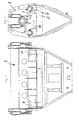
- Fig.1
- eine Seitenansicht und
- Fig.2
- eine Stirnansicht eines erfindungsgemäßen, als Mischer ausgebildeten Schüttgutbehälters,
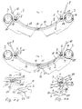
- Fig.3
- in vergrößertem Maßstab die Ausbildung der Fugen zwischen den Schmalseiten einer Öffnungsklappe und dem als Behälter dienenden Mischergehäuse einerseits im Bereich von Schwenkachsen und andererseits in dem Bereich, in dem zwei Öffnungsklappen zusammenstoßen,
- Fig.4
- eine der Fig.3 entsprechende Darstellung, bei welcher die in dieser Figur rechte Öffnungsklappe teilweise geöffnet ist,
- Fig.4a
- in noch weiter vergrößerter Darstellung eine Ansicht in Richtung einer ersten, parallel zu der Schwenkachse verlaufenden Schmalseite der Öffnungsklappe, die schräg angeordnet ist und die Gegenschräge der Entleeröffnung sowie den von der ersten Schmalseite beim Öffnen oder Schließen beschriebenen Kreis, an welchen diese erste Schmalseite und die Gegenschräge der Entleeröffnung angepaßt sind,
- Fig.4b
- im Maßstab der Fig.4a eine zweite Schmalseite der in Fig.4 rechts befindlichen Öffnungsklappe und ihren Öffnungs- oder Schließweg bzw. den diesem etwa entsprechenden Kreis sowie die zweite Schmalseite der zweiten Öffnungsklappe, die aber auch die Gegenschräge einer bis dort verlaufenden Entleeröffnung sein könnte,
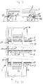
- Fig.5
- einen Längsschnitt des Behälters mit seiner Entleeröffnung,
- Fig.5a
- eine Ansicht der in Schließstellung befindlichen Öffnungsklappen von unten und jeweils eine ihrer ihre Schwenkachse bildenden Schwenklagerungen,
- Fig.6
- eine der Fig.3 entsprechende Darstellung, wobei der Behälter nur eine um eine Schwenkachse verschwenkbare Öffnungsklappe aufweist sowie
- Fig.7
- eine der Fig.6 entsprechende Darstellung, bei welcher die einzige Öffnungsklappe aus ihrer Schließstellung teilweise herausgeschwenkt ist, um bei einer weiteren Verschwenkung ihre etwa vertikale Öffnungsposition zu erreichen.
- Fig.1
- a side view and
- Fig.2
- 3 shows an end view of a bulk goods container according to the invention, designed as a mixer,
- Figure 3
- on an enlarged scale, the formation of the joints between the narrow sides of an opening flap and the mixer housing serving as a container on the one hand in the area of swivel axes and on the other hand in the area in which two opening flaps meet,
- Figure 4
- 3 shows a representation corresponding to FIG. 3, in which the opening flap on the right in this figure is partially open,
- 4a
- in a further enlarged view, a view in the direction of a first narrow side of the opening flap, which runs parallel to the pivot axis, which is arranged obliquely and the counter-bevels of the discharge opening and the circle described by the first narrow side when opening or closing, on which this first narrow side and the Counter slopes are adapted to the discharge opening,
- 4b
- on the scale of FIG. 4a, a second narrow side of the opening flap on the right in FIG. 4 and its opening or closing path or the circle approximately corresponding to this, as well as the second narrow side of the second opening flap, which could also be the counter slope of an emptying opening running there .
- Figure 5
- a longitudinal section of the container with its emptying opening,
- 5a
- 2 shows a view of the opening flaps in the closed position from below and in each case one of their pivot bearings forming their pivot axis,
- Figure 6
- a representation corresponding to Figure 3, wherein the container has only one pivotable about a pivot axis opening flap and
- Figure 7
- a representation corresponding to FIG. 6, in which the only opening flap is partially pivoted out of its closed position in order to reach its approximately vertical opening position upon further pivoting.
Ein im ganzen mit 1 bezeichneter Behälter dient zur Aufnahme und
im Ausführungsbeispiel auch zum Mischen von Schüttgut und ist in
diesem Falle etwa trommelförmig oder zylindrisch ausgebildet. An
seinem unteren Wandungsbereich ist eine Entleeröffnung vorgesehen,
die mit einer Öffnungsklappe 2 (Fig.6 und 7) oder mit zwei
flügelartig zueinander und voneinander weg verschwenkbaren
Öffnungsklappen 2 und 18 (Fig. 1 bis 5a) verschlossen werden kann.
Diese Öffnungsklappe(n) 2 (18) bilden also praktisch einen unteren
Wandbereich des Behälters 1.A container designated as a whole with 1 serves for receiving and
in the exemplary embodiment also for mixing bulk material and is in
in this case approximately drum-shaped or cylindrical. On
an emptying opening is provided in its lower wall area,
the one with an opening flap 2 (Fig. 6 and 7) or with two
wing-like to each other and pivotable away from each
Statt eines solchen etwa zylindrischen Behälters 1 könnte der
Behälter 1 aber auch beliebige andere Formen, beispielsweise auch
die Form eines Standsilos haben.Instead of such an approximately
An dieser Stelle sei schon erwähnt, daß in Fig.6 und 7 eine Anordnung
dargestellt ist, bei welcher der Behälter 1 nur eine einzige
Öffnungsklappe 2 hat.At this point it should be mentioned that in Fig. 6 and 7 an arrangement
is shown, in which the
Die jeweilige Öffnungsklappe 2 ist um eine Schwenkachse 3 schwenkbar
und hat in den Ausführungsbeispielen eine im wesentlichen rechteckige
Form, wobei sie aufgrund der Zylinderform des Behälters 1 zusätzlich
in einer Richtung auch noch eine Krümmung aufweist. Die Schwenkachse
3 wird dabei durch Scharniere 4 gebidet bzw. gelagert.The
In Fig.3, 4 und 4a sowie in Fig.6 und 7 erkennt man, daß die der
Schwenkachse 3 nahe oder parallele erste Schmalseite 5 der
Öffnungsklappe 2 in ihrem Querschnitt schräg ausgebildete ist, also
zwischen sich und einer Oberfläche der Öffnungsklappe 2 einen von
90° abweichenden Winkel einschließt. Die Behälter- oder Entleeröffnung
hat eine dazu derart passende Gegenschräge 6, daß die erste
Schmalseite 5 der Öffnungsklappe 2 und die Gegenschräge 6 des Randes
7 der Entleeröffnung in Gebrauchsstellung zumindest bereichsweise
etwa parallel zueinander verlaufen, also eine möglichst enge Fuge
bilden.In Fig.3, 4 and 4a and in Fig.6 and 7 you can see that the
Vor allem anhand der Figuren 3, 4 und 4a sowie der Figuren 6 und
7 wird deutlich, daß die im Querschnitt schräg angeordnete erste
Schmalseite 5 der Öffnungsklappe 2 mit der Oberfläche der Außenseite
8 dieser Öffnungsklappe 2 einen stumpfen Winkel, also einen Winkel
einschließt, der größer als 90° ist. Insbesondere in den Figuren
4, 7 und noch deutlicher in Fig.4a erkennt man, daß dabei der Verlauf
dieser Schmalseite 5 an den von ihr beim Öffnen oder Schließen
beschriebenen Kreis 9 um die Schwenkachse 3 zumindest angenähert
ist und ferner daß der Querschnitt der Gegenschräge 6 der
Entleeröffnung dazu passend mit der Außenseite 10 des Behälters
1 einen spitzen Winkel einschließt. Dementsprechend schließt die
schräge erste Schmalseite 5 der Öffnungsklappe 2, im Querschnitt
gesehen, mit deren Innenseite 11 einen spitzen Winkel ein, dessen
Kante 12 beim Verschwenken in Schließstellung als Abstreifer
zumindest an der Gegenschräge 6 dient. Vor allem beim Betrachten
der Fig.4a wird ganz deutlich, daß beim Verschließen der Öffnungsklappe
2 deren Schmalseite 5 mit der Kante 12 zuerst an die
Gegenschräge 6 gelangt und dort evtl. befindliches Schüttgut
abstreift und abschabt, wie umgekehrt die Gegenschräge auch an der
Schmalseite 5 befindliches Schüttgut abstreifen kann, so daß in
Schließstellung gem. Fig.3 zwischen der Schmalseite 5 und der
Gegenschräge 6 praktisch kein Schüttgut mehr vorhanden sein kann
und vor allem bei dieser Schließbewegung an dieser Stelle kein
Schüttgut eingeklemmt werden kann, welches die Schließbewegung beoder
verhindern könnte.Especially with reference to Figures 3, 4 and 4a and Figures 6 and
7 it is clear that the first is arranged obliquely in cross section
Vor allem in Fig.4b, aber auch in den Figuren 3, 4, 6 und 7 ist
dargestellt, daß auch die parallel zu der der Schwenkachse 3 nahen
ersten Schmalseite 5 verlaufende zweite Schmalseite 15 der
Öffnungsklappe 2 einen etwa schräg zur Außenseite 8 dieser Klappe
2 verlaufenden, insbesondere an den Kreis 16, der von ihr beim
Verschwenken um die Schwenkachse 3 beschrieben wird, angenäherte
Querschnittsform hat und daß die von der zweiten Schmalseite 15
in Schließstellung beaufschlagte Gegenschräge 17 an der Entleeröffnung
(Fig.6 und 7) oder an einer weiteren Öffnungsklappe 18 (Fig.3
und 4) eine dazu passende, etwaparallel verlaufende Querschnittsform
hat. Somit ergibt sich auch an dieser zweiten Schmalseite 15 der
Öffnungsklappe eine spitzwinkelige Kante 12 mit der Innenseite 11,
die beim Schließen gemäß Fig.4b an der Gegenschräge 17 eine schabende
Wirkung ausübt und somit ein Einklemmen von Schüttgut verhindert.
Die zweite Schmalseite 15 schließt also mit der Außenseite 8 der
Öffnungsklappe 2 ebenfalls einen stumpfen und mit der Innenseite
11 einen spitzen Winkel ein. Dabei dient, wie schon erwähnt, die
zwischen der Schmalseite 15 und der Innenseite 11 befindliche Kante
12 als Abstreifer an der Gegenschräge 17. Befindet sich diese
Gegenschräge 17 an einer weiteren Öffnungsklappe 18, ist lediglich
dafür zu sorgen, daß beim Schließen beider Öffnungsklappen zuerst
die Klappe 18 und dann die Klappe 2 geschlossen werden, damit die
an der zweiten Schmalseite 15 der Öffnungsklappe 2 befindliche
Abstreiferkante 12 wirksam werden kann. Da auch in diesem Falle
die Schmalseite 15 und die Gegenschräge 17 an den Schwenkkreis 16
angepaßt sind, der sich beim Verschwenken der Öffnungsklappe 2 um
die Schwenkachse 3 ergibt, ist wiederum in Schließstellung nur eine
derart enge Fuge zwischen Schmalseite 15 und Gegenschräge 17
vorhanden, das schon dadurch für viele Schüttgüter ein ausreichend
dichter Abschluß entsteht.Especially in Figure 4b, but also in Figures 3, 4, 6 and 7
shown that the parallel to that of the
In den Fig.4a und 4b ist erkennbar, daß der Querschnitt der ersten
Schmalseite 5 und der der zweiten Schmalseite 15 jeweils etwa einer
Tangente an den jeweiligen Schwenkkreis 9 und 16 oder Schwenkzylinder
dieser Schmalseiten um die Schwenkachse 3 der Öffnungsklappe 2
entspricht und die Schmalseiten 5 und 15 also im wesentlichen eben
ausgebildet sind. Dies läßt sich besonders einfach herstellen. Es
wäre aber auch eine leichte Krümmung in Anpassung an die Schwenkkreise
9 und 16 denkbar.In Figures 4a and 4b it can be seen that the cross section of the first
Es sei noch erwähnt, daß selbstverständlich bei einer Anordnung
gem. Fig.3 und 4 mit zwei Öffnungsklappen 2 und 18 diese zweite
Öffnungsklappe 18 im Bereich ihrer Schwenkachse 3 in gleicher Weise
mit einer schräg verlaufenden Schmalseite 5 und einer abstreifenden
Kante 12 versehen ist, die mit einer Gegenschräge 6 zusammenwirkt.It should also be mentioned that of course with an arrangement
gem. 3 and 4 with two opening
Der in den Ausführungsbeispielen dargestellte Schüttgutbehälter
1 hat eine (Fig.6 und 7) oder zwei (Fig.3 und 4) Öffnungsklappen
2 und 18, die gegenüber der Entleeröffnung mittels wenigstens einer
Dichtung 19 abgedichtet sind. Die Dichtung 19 ist als Dichtleiste
ausgebildet und dichtet die Fuge zwischen geschlossener Öffnungsklappe
2 und Gegenschräge 6 ab. Sie ist dazu der Fuge und der
Gegenschräge 6 benachbart an der Außenseite des Behälters 1
angeordnet, könnte aber auch an der Außenseite der Öffnungsklappe
2 und/oder 18 vorgesehen werden.The bulk material container shown in the
Ihre wirksame Dichtfläche 20 verläuft im Querschnitt gesehen im
Bereich des jeweiligen Schwenkkreises 9 und 16 oder Schwenkzylinders,
den die jeweilige Schmalseite 5 und 15 der Öffnungsklappe 2 oder
18 und eine zu diesen Schmalseiten benachbarte Anschlagleiste 21
beschreibt, wobei die Dichtfläche 20 oder die im Ausführungsbeispiel
an der Anschlagleiste 21 befindliche Gegenfläche 22 diesen jeweiligen
Schwenkkreis 9 oder 16 bzw. den entsprechenden Schwenkzylinder
berührt oder unter spitzem Winkel schneidet, was vor allem in Fig.4a
und 4b deutlich gemacht ist. Dadurch wird erreicht, daß die
Gegenfläche 22 beim Schließen der Klappe die entsprechende Dichtung
19 zunächst berührt im weiteren Schwenkverlauf aber mehr und mehr
an der Dichtfläche 20 unter Druck setzt und die Dichtleiste 19 im
Bereich ihrer Dichtfläche 20 verformt, so daß diese sich aufgrund
ihrer Nachgiebigkeit an die Gegenfläche 2 unter Druck anpaßt und
so die gewünschte Dichtwirkung erzielt.Their
Zwar könnte die Dichtung 19 an der Außenseite der Öffnungsklappe
2 sowie 18 vorgesehen sein, jedoch ist sie im Ausführungsbeispiel
an der Außenseite des Behälters 1 angeordnet und ihre Dichtfläche
20 befindet sich in Fortsetzung der Gegenschräge der Entleeröffnung,
was den Vorteil hat, daß die abstreifende Kante 12 der ersten und
der zweiten Schmalseite auch die Dichtfläche 20 selbsttätig beim
Schließen reinigt.Although the
Die Öffnungsklappe 2 und 18 weist in Fortsetzung ihrer Schmalseiten
5 und 15 außenseitig die schon kurz erwähnte, etwa parallel zu den
Schmalseiten verlaufende, mit ihr im Querschnitt einen stumpfen
Winkel bildende Anschlagleiste 21 zum Zusammenwirken mit der Dichtung
19 auf, deren der Dichtung zugewandte, im folgenden als Druckfläche
22 bezeichnete Gegenfläche im Querschnitt gesehen in Gebrauchsstellung
etwas schräg zu der Dichtfläche 20 verläuft und die Dichtung
in Gebrauchsstellung, also in Schließstellung, etwas mit Druck in
Umfangsrichtung des Behälters beaufschlagt und verdrängt.The
Die Dichtfläche 20 der als Dichtleiste ausgebildeten Dichtung 19
verläuft dabei in entspannter, nicht beaufschlagter Situation im
wesentlichen eben und diese Dichtleiste ist - von der Dichtfläche
20 und einem dieser benachbarten Verdrängungsbereich 24 abgesehen -
von einem Stützgehäuse 25 umschlossen, also gut gekammert gehalten.
Man erkennt vor allem in Fig. 4a, in gestrichelter Darstellung aber
auch in Fig.4b, daß das jeweilige Stützgehäuse 25 für die Dichtung
19 zusammen mit dieser quer zur Längserstreckung der Dichtung 19
und somit auch in Querrichtung zu den Schmalseiten 5 und 15
verstellbar und justierbar und insbesondere in Richtung zu der
Öffnungsklappe 2 und 18 hin verstellbar ist, in dem die Halteschrauben
26 für das Stützgehäuse gelöst und dieses dann beispielsweise
in Richtung entsprechend angeordneter Langlochungen verschoben
werden kann.The sealing
In Fig.4 und 7 einerseits sowie vor allem auch in Fig.5 und 5a
andererseits ist angedeutet, daß die quer oder rechtwinklig zu den
Schwenkachsen 2 der Öffnungsklappe 2 und 18 verlaufenden Schmalseiten
27 der Öffnungsklappe im Querschnitt gesehen mit ihren Außen- und
Innenseiten einen rechten Winkel bilden und die Ränder der
Entleeröffnung dazu passend geformt sind und daß im Bereich dieser
etwa rechtwinklig angeordneten Schmalseiten 27 außenseitig an dem
Rand der Entleeröffnung an dem Behälter 1 Dichtungen 19 vorgesehen
sind, die mit relativ zu ihnen geneigten Gegen- oder Druckflächen
22 in dem Sinne zusammenwirken, daß sie beim Schließen der
Öffnungsklappe 2 und/oder 18 durch diese relative Schrägung zunehmend
zusammendrückbar sind, wie dies auch bei den Dichtungen 19 an der
ersten Schmalseite 5 und der zweiten Schmalseite 15 der Fall ist.
Gegebenenfalls könnte dabei die Dichtung auch an der Öffnungsklappe
vorgesehen sein. In Fig. 4 and 7 on the one hand and especially in Fig. 5 and 5a
on the other hand, it is indicated that the transverse or perpendicular to the
Pivot axes 2 of the
In Fig.5 ist im linken Teil die Schließstellung dargestellt, in
welcher die Gegen- oder Druckfläche 22 einer an der Außenseite der
Öffnungsklappe befindlichen Anschlagleiste 21 die Dichtung 19 an
der Dichtfläche in schräger Richtung zusammendrückt, während im
rechten Teil der Fig.5 die Öffnungsklappe mit ihrer Anschlagleiste
21 und deren Gegenfläche 22 schon soweit in Öffnungsstellung
verschwenkt ist, daß die Dichtung 19 und ihre Dichtfläche 20
freigegeben sind.5 shows the closed position in the left part, in
which the counter or
Bei einer rechteckigen Öffnungsklappe 2 ist also an allen vier
Schmalseiten eine effektive Dichtung vorhanden, die beim Schließen
der Öffnungsklappe selbsttätig durch entsprechende abstreifende
Kanten der Öffnungsklappe gereinigt wird und deren Dichtfläche im
Querschnitt gesehen im wesentlichen vertikal oder abwärtsgerichtet
verläuft, so daß schon deshalb praktisch kein Material daran haften
bleiben kann. Sollte dies aber dennoch geschehen, wird die Dichtung
an ihrer Dichtfläche 20 beim Schließen der Öffnungsklappe in der
schon beschriebenen Weise mit deren innenliegenden Kanten abgestreift
und somit selbsttätig gereinigt.With a
Dabei ist an diesen Dichtungen und insbesondere an der Dichtung
19 im Bereich der ersten Schmalseite 5 als besonders vorteilhaft
anzusehen, daß zunächst beim Schließen der Öffnungsklappe die
automatische Reinigung durch die Kante 12 der Schmalseite 5 erfolgt,
wonach dann anschließend die allmähliche zunehmende Zusammendrückung
der Dichtung 19 aufgrund der etwas unterschiealichen Schrägung der
Druckfläche 22 gegenüber der Dichtfläche 20 erfolgt.It is on these seals and in particular on the
Der Schüttgutbehälter insbesondere für Baustoffe oder Baustoffmischungen
hat wenigstens eine um eine etwa horizontale Schwenkachse
3 schwenkbare, in der Regel rechteckige Öffnungsklappe 2 zum
Verschließen einer unteren Entleeröffnung. Die Schwenkachse 3
befindet sich dabei nahe oder parallel einer ersten Schmalseite
5 dieser Öffnungsklappe 2 und diese erste Schmalseite 5 ist über
wenigstens einen Teil ihres Querschnittes schräg angeordnet, so
daß sie mit der Oberfläche der Außenseite 8 dieser Öffnungsklappe
2 einen stumpfen Winkel bildet. Die Behälter- oder Entleeröffnung
hat an dem dazugehörenden Rand eine dazu passende Gegenschräge,
so daß die erste Schmalseite 5 der Öffnungsklappe 2 und diese
Gegenschräge 6 der Entleeröffnung in Gebrauchsstellung zumindest
bereichsweise etwa parallel zueinander verlaufen. Der stumpfe Winkel
an der ersten Schmalseite 5 ist dabei so gewählt, daß der Verlauf
dieser schrägen Schmalseite 5 an den von dieser Schmalseite beim
Öffnen und Schließen beschriebenen Kreis 9 um die Schwenkachse 3
zumindest angenähert ist.The bulk container especially for building materials or building material mixtures
has at least one about an approximately
Claims (11)
- A bulk goods container, especially a container (1) for building materials or building material mixtures, with at least one especially rectangular opening flap (2) which can be swivelled about a swivelling axis (3) to close an emptying opening of the container (1), wherein at least the first narrow side if this opening flap (2), which is adjacent or parallel to the swivelling axis (3), is configured to slope over at least a part of its cross-section and encloses an angle which deviates from 90° between itself and the surface of the opening flap (2), wherein the container or emptying opening has a counter-slope (6) which matches it in such a way that the first narrow side (5) of the opening flap (2) and the counter-slope (6) of the emptying opening extend approximately parallel to one another, at least in part, when in the position of use, wherein the first narrow side (5) of the opening flap (2), disposed obliquely in cross-section, encloses an obtuse angle with the surface of the external side (8) of this opening flap (2) and wherein the course of this narrow side (5) at least approximates the circle (9) described about the swivelling axis (3) of the opening flap when opening and closing, characterised in that the cross-section of the counter-slope (6) of the emptying opening, fitting together with the external side (10) of the container (1), encloses an acute angle, that the opening flap (2) is sealed with regard to the emptying opening by means of at least one seal (19) and that the seal (19), as a sealing strip, is disposed on the external side adjacent to the groove between the closed opening flap (2, 18) and the counter-slope (6, 17), and its effective sealing surface (20), when seen in cross-section, extends in the area of the swivelling circle (9, 16) or swivelling cylinder described by the narrow side (5, 15) of the opening flap (2) and/or a detent bar (21) adjacent thereto, wherein the sealing surface (20) and/or the counter-surface (22) touches this swivelling circle (9, 16) or swivelling cylinder or intersects it at an acute angle.
- A bulk goods container according to claim 1, characterised in that when seen in cross-section, the slanted first narrow side (5) of the opening flap (2) encloses an acute angle with its internal side, the edge (12) of which serves as a scraper, at least on the counter-surface (6) when swivelling into the closed position.
- A bulk goods container according to one of claims 1 to 2, characterised in that the second narrow side (15) of the opening flap (2) which extends parallel to the first narrow side (5) which is adjacent to the swivelling axis (3) also has a cross-sectional shape which extends approximately obliquely to the external side (8) of the flap (2), especially approximating the circle (16) described by it when swivelling about the swivelling axis (3) and that on the emptying opening or on a further opening flap (18), the counter-slope (17) which is contacted by the second narrow side (15) in the closed position has a matching cross-sectional shape extending approximately in parallel.
- A bulk goods container according to one of claims 1 to 3, characterised in that the second narrow side (15) encloses an oblique angle with the external side of the opening flap (2) and an acute angle with the internal side of the opening flap (2) and the edge (12) disposed between the narrow side (15) and the internal side (11) serves as a scraper.
- A bulk goods container according to one of claims 1 to 4, characterised in that the cross-section of the first and/or the second narrow side (5, 15) approximately corresponds to a tangent of the respective swivelling circle (9, 16) or swivelling cylinder of these narrow sides about the swivelling axis (3) of the opening flap (2) and the narrow side(s) is (are) configured to be substantially flat.
- A bulk goods container according to one of the preceding claims, characterised in that the opening flap has a large wall thickness and/or thickness, and that the narrow side(s) has (have) a polygonal cross-section, that is, areas with different degrees of obliqueness, wherein these areas each correspond to tangents of the enveloping circle or the enveloping cylinder which is described by the narrow side(s) when swivelling the opening flap.
- A bulk goods container according to one of claims 1 to 6, characterised in that for polygonal shaping, the narrow side(s) and/or the counter-slope(s) have at least two flat areas disposed at an angle to one another, wherein the angle between them is obtuse.
- A bulk goods container according to claim 1, characterised in that the seal on the outside of the container and its sealing surface (20) is disposed approximately as a continuation of the counter-slope of the emptying opening, and, in continuation of its narrow side (5, 15), the opening flap (2, 18) has, on its external side, a detent strip (21) extending approximately parallel to the narrow side and which forms an obtuse angle therewith, to work together with this seal (19), whose pressure surface (22) which faces the seal extends, when seen in cross-section, approximately obliquely to the sealing surface (20) of the seal in its position of use and somewhat displaces the seal in this position of use.
- A bulk goods container according to claim 1 or 8, characterised in that the seal (19) is configured as a sealing strip whose sealing surface (20) extends in a substantially flat manner when relaxed and not contacted, and that this sealing strip is preferably enclosed by the sealing surface (20) and a displacement area (24) adjacent thereto, partially or completely apart from a supporting housing (25).
- A bulk goods container according to claim 9, characterised in that the supporting housing (25) for the seal (19) is moveable and adjustable together with this, especially in the direction towards the opening flap (2, 18).
- A bulk goods container according to one of claims 1 to 10, characterised in that the narrow sides (27) of the opening flap which extend transverse or at right-angles to the swivelling axis (2) of the opening flap (2, 18), seen in cross-section, form a right-angle with their external and internal sides, and the edges of the emptying opening are formed to as to match them, and that seals (19) are provided in the area of these narrow sides which are approximately disposed at right-angles, preferably externally on the edge of the emptying opening or the opening flap, these seals working together with counter-surfaces (22) which are angled relative thereto, so that they can be increasingly compressed when the opening flap (2, 18) is closed by this relative obliqueness.
Applications Claiming Priority (2)
| Application Number | Priority Date | Filing Date | Title |
|---|---|---|---|
| DE29804378U DE29804378U1 (en) | 1998-03-12 | 1998-03-12 | Bulk goods container with an opening flap that can be swiveled around an axis |
| DE29804378U | 1998-03-12 |
Publications (2)
| Publication Number | Publication Date |
|---|---|
| EP0941947A1 EP0941947A1 (en) | 1999-09-15 |
| EP0941947B1 true EP0941947B1 (en) | 2002-06-12 |
Family
ID=8054001
Family Applications (1)
| Application Number | Title | Priority Date | Filing Date |
|---|---|---|---|
| EP99104227A Expired - Lifetime EP0941947B1 (en) | 1998-03-12 | 1999-03-03 | Bulk material container with hinged opening door pivotable about an axis |
Country Status (2)
| Country | Link |
|---|---|
| EP (1) | EP0941947B1 (en) |
| DE (2) | DE29804378U1 (en) |
Cited By (1)
| Publication number | Priority date | Publication date | Assignee | Title |
|---|---|---|---|---|
| US8225458B1 (en) | 2001-07-13 | 2012-07-24 | Hoffberg Steven M | Intelligent door restraint |
Family Cites Families (4)
| Publication number | Priority date | Publication date | Assignee | Title |
|---|---|---|---|---|
| DE344691C (en) * | ||||
| DE2903951C3 (en) * | 1979-02-02 | 1985-01-03 | Eirich, Hubert | Device for closing an emptying opening in a container bottom |
| DE3337437A1 (en) * | 1983-10-14 | 1985-05-02 | Mathis System-Technik GmbH, 7844 Neuenburg | BATCH MIXER |
| CH689667A5 (en) * | 1994-04-29 | 1999-08-13 | Buehler Ag | Batch mixer. |
-
1998
- 1998-03-12 DE DE29804378U patent/DE29804378U1/en not_active Expired - Lifetime
-
1999
- 1999-03-03 DE DE59901692T patent/DE59901692D1/en not_active Expired - Lifetime
- 1999-03-03 EP EP99104227A patent/EP0941947B1/en not_active Expired - Lifetime
Cited By (3)
| Publication number | Priority date | Publication date | Assignee | Title |
|---|---|---|---|---|
| US8225458B1 (en) | 2001-07-13 | 2012-07-24 | Hoffberg Steven M | Intelligent door restraint |
| US9045927B1 (en) | 2001-07-13 | 2015-06-02 | Steven M. Hoffberg | Intelligent door restraint |
| US9121217B1 (en) | 2001-07-13 | 2015-09-01 | Steven M. Hoffberg | Intelligent door restraint |
Also Published As
| Publication number | Publication date |
|---|---|
| DE29804378U1 (en) | 1998-06-04 |
| EP0941947A1 (en) | 1999-09-15 |
| DE59901692D1 (en) | 2002-07-18 |
Similar Documents
| Publication | Publication Date | Title |
|---|---|---|
| DE102006039868A1 (en) | Frame, preferably a fly screen frame | |
| EP0142003B1 (en) | Batch mixer | |
| DE3921339A1 (en) | PACKING FROM A ONE-PIECE CUTTING PIECE | |
| DE2105020A1 (en) | Mixing device | |
| DE19714465C1 (en) | Elastic extruded seal for window or door | |
| CH691616A5 (en) | Plastic window and method for its production. | |
| EP0941947B1 (en) | Bulk material container with hinged opening door pivotable about an axis | |
| DE202006020221U1 (en) | Frame, preferably a fly screen frame | |
| EP1780369A1 (en) | Flexible extruded seal for windows, doors etc | |
| DE3922995C2 (en) | ||
| DE3915528C1 (en) | Screw conveyor with material moisture reduction - has spiral brush in grate region, matching pitch of conveyor screw | |
| WO2004029395A2 (en) | Device preventing fingers from getting caught in a door leaf of a sectional door or folding door, said door leaf comprising hingedly interconnected sections | |
| DE19809255A1 (en) | Cartridge for holding a viscous or pasty mass | |
| DE4240971C1 (en) | Meat grinding filling chamber - has slide to cover filling opening with chamfered cutting edge to sever sinews and seal the opening | |
| EP0003132B1 (en) | Closure cap for a container | |
| EP1288413B1 (en) | Check device for a tilt- and/or turn-wing of a window or a door | |
| AT390123B (en) | PROFILE STRING GASKET MADE OF ELASTIC MATERIAL FOR WINDOWS, DOORS OR THE LIKE. | |
| EP0416152A1 (en) | Finger guard for overhead doors | |
| DE102007006339B4 (en) | Door for a shredder | |
| DE202005019332U1 (en) | Sealing profile used in e.g. car window, door, has weak sections distributed in 180-degree area, while remaining sections and outer side of sealing profile are provided with reinforcements | |
| AT390300B (en) | ELASTIC SEALING PROFILE FOR WINDOWS OR THE LIKE ROOM LOCKING BODIES | |
| DE60205154T2 (en) | Head for compacting waste materials | |
| EP3342973A1 (en) | Pivoting and/or sliding door assembly | |
| DE2403078C2 (en) | Containers for bulk goods | |
| DE8403073U1 (en) | SWINGARM AND TURN WING |
Legal Events
| Date | Code | Title | Description |
|---|---|---|---|
| PUAI | Public reference made under article 153(3) epc to a published international application that has entered the european phase |
Free format text: ORIGINAL CODE: 0009012 |
|
| AK | Designated contracting states |
Kind code of ref document: A1 Designated state(s): DE FR IT |
|
| AX | Request for extension of the european patent |
Free format text: AL;LT;LV;MK;RO;SI |
|
| 17P | Request for examination filed |
Effective date: 19990821 |
|
| AKX | Designation fees paid |
Free format text: DE FR IT |
|
| RIN1 | Information on inventor provided before grant (corrected) |
Inventor name: ELSAESSER, BERND Inventor name: KNOEPFLE XAVER Inventor name: DILGER UDO |
|
| 17Q | First examination report despatched |
Effective date: 20010313 |
|
| GRAG | Despatch of communication of intention to grant |
Free format text: ORIGINAL CODE: EPIDOS AGRA |
|
| GRAG | Despatch of communication of intention to grant |
Free format text: ORIGINAL CODE: EPIDOS AGRA |
|
| GRAH | Despatch of communication of intention to grant a patent |
Free format text: ORIGINAL CODE: EPIDOS IGRA |
|
| GRAH | Despatch of communication of intention to grant a patent |
Free format text: ORIGINAL CODE: EPIDOS IGRA |
|
| GRAA | (expected) grant |
Free format text: ORIGINAL CODE: 0009210 |
|
| AK | Designated contracting states |
Kind code of ref document: B1 Designated state(s): DE FR IT |
|
| REF | Corresponds to: |
Ref document number: 59901692 Country of ref document: DE Date of ref document: 20020718 |
|
| ET | Fr: translation filed | ||
| PLBE | No opposition filed within time limit |
Free format text: ORIGINAL CODE: 0009261 |
|
| STAA | Information on the status of an ep patent application or granted ep patent |
Free format text: STATUS: NO OPPOSITION FILED WITHIN TIME LIMIT |
|
| 26N | No opposition filed |
Effective date: 20030313 |
|
| REG | Reference to a national code |
Ref country code: FR Ref legal event code: PLFP Year of fee payment: 18 |
|
| REG | Reference to a national code |
Ref country code: FR Ref legal event code: PLFP Year of fee payment: 19 |
|
| PGFP | Annual fee paid to national office [announced via postgrant information from national office to epo] |
Ref country code: FR Payment date: 20170119 Year of fee payment: 19 |
|
| PGFP | Annual fee paid to national office [announced via postgrant information from national office to epo] |
Ref country code: IT Payment date: 20170328 Year of fee payment: 19 |
|
| PGFP | Annual fee paid to national office [announced via postgrant information from national office to epo] |
Ref country code: DE Payment date: 20170411 Year of fee payment: 19 |
|
| REG | Reference to a national code |
Ref country code: DE Ref legal event code: R119 Ref document number: 59901692 Country of ref document: DE |
|
| PG25 | Lapsed in a contracting state [announced via postgrant information from national office to epo] |
Ref country code: DE Free format text: LAPSE BECAUSE OF NON-PAYMENT OF DUE FEES Effective date: 20181002 |
|
| PG25 | Lapsed in a contracting state [announced via postgrant information from national office to epo] |
Ref country code: IT Free format text: LAPSE BECAUSE OF NON-PAYMENT OF DUE FEES Effective date: 20180303 |
|
| PG25 | Lapsed in a contracting state [announced via postgrant information from national office to epo] |
Ref country code: FR Free format text: LAPSE BECAUSE OF NON-PAYMENT OF DUE FEES Effective date: 20180331 |