EP0938197A2 - High capacity chirped-pulse wavelength-division multiplexed communication method and apparatus - Google Patents
High capacity chirped-pulse wavelength-division multiplexed communication method and apparatus Download PDFInfo
- Publication number
- EP0938197A2 EP0938197A2 EP99300951A EP99300951A EP0938197A2 EP 0938197 A2 EP0938197 A2 EP 0938197A2 EP 99300951 A EP99300951 A EP 99300951A EP 99300951 A EP99300951 A EP 99300951A EP 0938197 A2 EP0938197 A2 EP 0938197A2
- Authority
- EP
- European Patent Office
- Prior art keywords
- division multiplexed
- chirped
- capacity
- communications apparatus
- optical
- Prior art date
- Legal status (The legal status is an assumption and is not a legal conclusion. Google has not performed a legal analysis and makes no representation as to the accuracy of the status listed.)
- Withdrawn
Links
Images


Classifications
-
- H—ELECTRICITY
- H04—ELECTRIC COMMUNICATION TECHNIQUE
- H04J—MULTIPLEX COMMUNICATION
- H04J14/00—Optical multiplex systems
- H04J14/02—Wavelength-division multiplex systems
-
- H—ELECTRICITY
- H04—ELECTRIC COMMUNICATION TECHNIQUE
- H04B—TRANSMISSION
- H04B10/00—Transmission systems employing electromagnetic waves other than radio-waves, e.g. infrared, visible or ultraviolet light, or employing corpuscular radiation, e.g. quantum communication
- H04B10/50—Transmitters
- H04B10/501—Structural aspects
- H04B10/503—Laser transmitters
- H04B10/505—Laser transmitters using external modulation
- H04B10/5059—Laser transmitters using external modulation using a feed-forward signal generated by analysing the optical or electrical input
- H04B10/50595—Laser transmitters using external modulation using a feed-forward signal generated by analysing the optical or electrical input to control the modulator DC bias
-
- H—ELECTRICITY
- H04—ELECTRIC COMMUNICATION TECHNIQUE
- H04B—TRANSMISSION
- H04B10/00—Transmission systems employing electromagnetic waves other than radio-waves, e.g. infrared, visible or ultraviolet light, or employing corpuscular radiation, e.g. quantum communication
- H04B10/50—Transmitters
- H04B10/501—Structural aspects
- H04B10/506—Multiwavelength transmitters
-
- H—ELECTRICITY
- H04—ELECTRIC COMMUNICATION TECHNIQUE
- H04B—TRANSMISSION
- H04B10/00—Transmission systems employing electromagnetic waves other than radio-waves, e.g. infrared, visible or ultraviolet light, or employing corpuscular radiation, e.g. quantum communication
- H04B10/50—Transmitters
- H04B10/508—Pulse generation, e.g. generation of solitons
-
- H—ELECTRICITY
- H01—ELECTRIC ELEMENTS
- H01S—DEVICES USING THE PROCESS OF LIGHT AMPLIFICATION BY STIMULATED EMISSION OF RADIATION [LASER] TO AMPLIFY OR GENERATE LIGHT; DEVICES USING STIMULATED EMISSION OF ELECTROMAGNETIC RADIATION IN WAVE RANGES OTHER THAN OPTICAL
- H01S3/00—Lasers, i.e. devices using stimulated emission of electromagnetic radiation in the infrared, visible or ultraviolet wave range
- H01S3/005—Optical devices external to the laser cavity, specially adapted for lasers, e.g. for homogenisation of the beam or for manipulating laser pulses, e.g. pulse shaping
- H01S3/0057—Temporal shaping, e.g. pulse compression, frequency chirping
-
- H—ELECTRICITY
- H01—ELECTRIC ELEMENTS
- H01S—DEVICES USING THE PROCESS OF LIGHT AMPLIFICATION BY STIMULATED EMISSION OF RADIATION [LASER] TO AMPLIFY OR GENERATE LIGHT; DEVICES USING STIMULATED EMISSION OF ELECTROMAGNETIC RADIATION IN WAVE RANGES OTHER THAN OPTICAL
- H01S3/00—Lasers, i.e. devices using stimulated emission of electromagnetic radiation in the infrared, visible or ultraviolet wave range
- H01S3/005—Optical devices external to the laser cavity, specially adapted for lasers, e.g. for homogenisation of the beam or for manipulating laser pulses, e.g. pulse shaping
- H01S3/0085—Modulating the output, i.e. the laser beam is modulated outside the laser cavity
-
- H—ELECTRICITY
- H01—ELECTRIC ELEMENTS
- H01S—DEVICES USING THE PROCESS OF LIGHT AMPLIFICATION BY STIMULATED EMISSION OF RADIATION [LASER] TO AMPLIFY OR GENERATE LIGHT; DEVICES USING STIMULATED EMISSION OF ELECTROMAGNETIC RADIATION IN WAVE RANGES OTHER THAN OPTICAL
- H01S3/00—Lasers, i.e. devices using stimulated emission of electromagnetic radiation in the infrared, visible or ultraviolet wave range
- H01S3/05—Construction or shape of optical resonators; Accommodation of active medium therein; Shape of active medium
- H01S3/06—Construction or shape of active medium
- H01S3/063—Waveguide lasers, i.e. whereby the dimensions of the waveguide are of the order of the light wavelength
- H01S3/067—Fibre lasers
- H01S3/06754—Fibre amplifiers
-
- H—ELECTRICITY
- H01—ELECTRIC ELEMENTS
- H01S—DEVICES USING THE PROCESS OF LIGHT AMPLIFICATION BY STIMULATED EMISSION OF RADIATION [LASER] TO AMPLIFY OR GENERATE LIGHT; DEVICES USING STIMULATED EMISSION OF ELECTROMAGNETIC RADIATION IN WAVE RANGES OTHER THAN OPTICAL
- H01S3/00—Lasers, i.e. devices using stimulated emission of electromagnetic radiation in the infrared, visible or ultraviolet wave range
- H01S3/23—Arrangements of two or more lasers not provided for in groups H01S3/02 - H01S3/22, e.g. tandem arrangements of separate active media
- H01S3/2383—Parallel arrangements
Definitions
- This invention relates generally to the field of optical communications systems and in particular to a high-capacity, chirped-pulse multiple wavelength communications method and apparatus.
- Optical communications devices and methods employing same are a substantial and fast-growing constituent of communications networks.
- Applications of such methods and devices include, but are not limited to, telecommunications systems, cable television, and local area networks (LANs).
- LANs local area networks
- Wavelength division multiplexing has been shown as a promising approach for increasing the capacity of existing fiber optic networks.
- a communications system employing WDM uses plural optical signal channels, each channel being assigned a particular channel wavelength.
- optical signal channels are generated, multiplexed to form an optical signal comprised of the individual optical signal channels, transmitted over a single waveguide, and demultiplexed such that each channel wavelength is individually routed to a designated receiver.
- optical amplifiers such as doped fiber amplifiers, plural channels are directly amplified simultaneously, facilitating the use of WDM systems in long-distance applications.
- laser pulses become chirped as they propagate through a dispersive delay line such as an optical fiber that introduces a time delay between their frequency components.
- Frequency bands that are useful as WDM channels are then selected from the pulses' continuous spectra through the action of a modulator operating at a multiple of the laser repetition rate, i.e., 36.7 MHz.
- a modelocked erbium doped fiber-ring laser is used as the source of sub-picosecond laser pulses with a bandwidth of > 70nm and a repetition rate of 36.7 MHz.
- the spectrum of each pulse is mapped onto the time axis as it propagates through a single mode fiber that has a total dispersion of -340 psec/nm. This propagation stretches out the pulses to a duration of about 24.2 nsec and provides a nearly linear relationship between wavelength and time delay within each pulse.
- a TDM electroabsorption modulator that has a 12-GHz bandwidth is installed at the output of the chirping fiber to define and encode data onto each channel in a time-sequential manner. It uses a TDM multiplexed pattern generator synchronized to the 271 st harmonic, or 9.942 GHz of the laser repetition rate. The short-wavelength absorption edge of the modulator results in the spectral narrowing of the pulses to about 28 nm. To partially restore the original bandwidth and to equalize the transmitted spectrum, the modulator bias is adjusted dynamically using feed-forward equalization as each pulse passes through.
- a single TDM modulator can be used to encode data on all channels. Accordingly, a 271-bit TDM "word" is used for every pulse to encode data onto each of the 271 frequency slots defined by the modulator. When the same word is used for each pulse, a stable optical spectrum is obtained.
- the chirping fiber converts the TDM pattern into a WDM modulation with states "1" and "0" corresponding to high-and low-intensity frequency bands, respectively. Out of 271 possible wavelength slots defined by the modulator, 206 have been identified with sufficient optical power.
- the chirped-pulse WDM provides hundreds of WDM channels from a single source without the need to stabilize the wavelength of each channel. Consequently, there is a continuing need for an efficient and cost-effective WDM methods and apparatus that permit transmitting a large number of spectral channels.
- the present invention is directed to a method and apparatus for providing high-capacity, chirped-pulse wavelength-division multiplexed communications in which a chirped-pulse, wavelength-division multiplexed signal is further optically multiplexed.
- the present invention is directed to an apparatus including: a multifrequency optical source for supplying an optical signal having a plurality of wavelength division multiplexed (WDM) channels; a power splitter for splitting the optical signal from the multifrequency source into a number of signals; a number of time delay lines, for delaying each one of the signals independently; a number of data encoding modulators for modulating each one of the delayed signals; and a power combiner for combining the number of delayed, modulated signals into a single signal such that the multifrequency optical source signal is multiplexed by a desired amount.
- WDM wavelength division multiplexed
- the present invention is directed to a method for operating a high-capacity, chirped-pulse wavelength-division multiplexed communications apparatus whereby an optical signal having a plurality of wavelength division multiplexed channels is generated, split, delayed by a desired amount, modulated and then combined into a single signal such that individual WDM channels are in temporally spaced relation to one another.
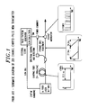
- FIG. 2 shows a schematic of an exemplary optical chirped-pulse wavelength-division multiplexed transmitter in accordance with the present invention.
- light pulses with a bandwidth in excess of 80nm are extracted from a modelocked laser 202 having a repetition rate of 36.7 MHz.
- the spectrum of each pulse is mapped onto the time axis by propagation through 16 km (round trip) of standard, single mode chirping fiber 204 ( D ⁇ 17 ps/km/nm), causing the pulses to be stretched to a duration of approximately 24ns.
- a Faraday rotator mirror 206 inserted substantially halfway along the length of the chirping fiber 204, rotates the polarization of the light by 90 degrees and advantageously eliminates polarization mode dispersion through the chirping fiber.
- the chirped pulses propagate through circulator 207, through polarization controller 208 and into modulator 210.
- PRBS pseudo-random bit sequence
- the data stream is then amplified, by gain-flattened, erbium-doped fiber power amplifier 212 and then input to optical multiplexer 214 used in an experiment for multiplexing pseudorandom data streams.
- the bit rate of the data stream is increased 64 times, to 2.35 Gb/s.
- an illustrative transmission system comprising 71 km of single mode fiber (SMF), an erbium-doped fiber line amplifier, and 9 km of dispersion compensating fiber (DCF).
- SMF single mode fiber
- DCF dispersion compensating fiber
- FIG. 3(a) shows the output of the optical multiplexer 214 when no data is encoded at the input.
- FIG. 3(b) shows the output spectrum of the optical multiplexer 214 when the same 336-bit TDM word "11001100... 1100" is encoded on every pulse. From this figure, 294 wavelength channels can be identified with less than 3 dB channel variation. The total output power integrated over all channels is -15 dBm.
- FIG 4(a) shows how the spectrum narrows to 128 channels when a broadband, gain-flattened erbium-doped fiber amplifier with a 37 nm bandwidth (3 dB) is inserted at the input of the optical multiplexer 214.
- the total output power over this bandwidth is 2.3 dBm.
- FIG 4(b) shows an eye diagram obtained with a recovered clock at the output of the OTDM stage for the channel centered at 1542.93 nm.
- FIG 4(c) and FIG 4(d) show the same spectrum and eye diagram after propagation through illustrative transmission system 216. As those skilled in the art will quickly recognize, a slight change of the spectrum is seen, but no degradation of the eye is apparent.
Landscapes
- Physics & Mathematics (AREA)
- Engineering & Computer Science (AREA)
- Computer Networks & Wireless Communication (AREA)
- Signal Processing (AREA)
- Electromagnetism (AREA)
- Optics & Photonics (AREA)
- Optical Communication System (AREA)
- Lasers (AREA)
Abstract
Description
- This invention relates generally to the field of optical communications systems and in particular to a high-capacity, chirped-pulse multiple wavelength communications method and apparatus.
- Optical communications devices and methods employing same are a substantial and fast-growing constituent of communications networks. Applications of such methods and devices include, but are not limited to, telecommunications systems, cable television, and local area networks (LANs).
- As the demand for such applications increases however, the current capacity of existing waveguiding media is limited. And while the capacity of the media may be expanded, e.g., by deploying more fiber optic cables, the cost of such expansion is prohibitive. Consequently, there has been a great demand for cost-effective methods and apparatus that increase the capacity of existing optical waveguides.
- Wavelength division multiplexing (WDM) has been shown as a promising approach for increasing the capacity of existing fiber optic networks. A communications system employing WDM uses plural optical signal channels, each channel being assigned a particular channel wavelength. In such a WDM system, optical signal channels are generated, multiplexed to form an optical signal comprised of the individual optical signal channels, transmitted over a single waveguide, and demultiplexed such that each channel wavelength is individually routed to a designated receiver. Through the use of optical amplifiers, such as doped fiber amplifiers, plural channels are directly amplified simultaneously, facilitating the use of WDM systems in long-distance applications.
- United States Patent No. 5,631,758 issued to Knox et al. on May 20, 1997 disclosed a Chirped-Pulse Multiple Wavelength Telecommunications System. This patent, which is assigned to the assignee of the present application, is expressly incorporated herein by reference. As described therein, a chirped-pulse-WDM technique defines and encodes data on a large number of channels using a spectrally broadband source and a single modulator.
- With this chirped-pulse WDM technique, laser pulses become chirped as they propagate through a dispersive delay line such as an optical fiber that introduces a time delay between their frequency components. Frequency bands that are useful as WDM channels are then selected from the pulses' continuous spectra through the action of a modulator operating at a multiple of the laser repetition rate, i.e., 36.7 MHz.
- Proof of the effectiveness of the WDM technique was described by L.Boivin, M.C.Nuss, W.H.Knox and J.B.Stark in an article entitled "206-Channel Chirped-Pulse Wavelength Division Multiplexed Transmitter" that appeared in Electronics Letters, Vol.33, No. 10, pp. 827-828, 8th April, 1997 and incorporated herein by reference. As disclosed in this article and shown in schematic form in FIG 1, a single femtosecond laser, a single dispersive optical fiber, and a single time-division-multiplexed electroabsorption modulator (EAM) is used to generate the 206 useful channels.
- The single laser is used because combining and stabilizing a large number of single frequency lasers is prohibitively complicated and expensive. A modelocked erbium doped fiber-ring laser is used as the source of sub-picosecond laser pulses with a bandwidth of > 70nm and a repetition rate of 36.7 MHz. The spectrum of each pulse is mapped onto the time axis as it propagates through a single mode fiber that has a total dispersion of -340 psec/nm. This propagation stretches out the pulses to a duration of about 24.2 nsec and provides a nearly linear relationship between wavelength and time delay within each pulse.
- A TDM electroabsorption modulator that has a 12-GHz bandwidth is installed at the output of the chirping fiber to define and encode data onto each channel in a time-sequential manner. It uses a TDM multiplexed pattern generator synchronized to the 271st harmonic, or 9.942 GHz of the laser repetition rate. The short-wavelength absorption edge of the modulator results in the spectral narrowing of the pulses to about 28 nm. To partially restore the original bandwidth and to equalize the transmitted spectrum, the modulator bias is adjusted dynamically using feed-forward equalization as each pulse passes through.
- Additionally, when the frequency components of the short pulse laser are separated temporarily by propagation in a dispersive medium, a single TDM modulator can be used to encode data on all channels. Accordingly, a 271-bit TDM "word" is used for every pulse to encode data onto each of the 271 frequency slots defined by the modulator. When the same word is used for each pulse, a stable optical spectrum is obtained. The chirping fiber converts the TDM pattern into a WDM modulation with states "1" and "0" corresponding to high-and low-intensity frequency bands, respectively. Out of 271 possible wavelength slots defined by the modulator, 206 have been identified with sufficient optical power.
- As can be readily appreciated, the larger the number of wavelength channels, the lower the speed at which related electronics have to operate thereby decreasing overall system cost. Also, the chirped-pulse WDM provides hundreds of WDM channels from a single source without the need to stabilize the wavelength of each channel. Consequently, there is a continuing need for an efficient and cost-effective WDM methods and apparatus that permit transmitting a large number of spectral channels.
- An advance is made over the prior and in particular we overcome the capacity limitations of the prior art chirped-pulse WDM systems which is limited in capacity to the modulation speed of the TDM modulator. Accordingly the present invention is directed to a method and apparatus for providing high-capacity, chirped-pulse wavelength-division multiplexed communications in which a chirped-pulse, wavelength-division multiplexed signal is further optically multiplexed.
- Viewed from one aspect, the present invention is directed to an apparatus including: a multifrequency optical source for supplying an optical signal having a plurality of wavelength division multiplexed (WDM) channels; a power splitter for splitting the optical signal from the multifrequency source into a number of signals; a number of time delay lines, for delaying each one of the signals independently; a number of data encoding modulators for modulating each one of the delayed signals; and a power combiner for combining the number of delayed, modulated signals into a single signal such that the multifrequency optical source signal is multiplexed by a desired amount.
- Viewed from another aspect, the present invention is directed to a method for operating a high-capacity, chirped-pulse wavelength-division multiplexed communications apparatus whereby an optical signal having a plurality of wavelength division multiplexed channels is generated, split, delayed by a desired amount, modulated and then combined into a single signal such that individual WDM channels are in temporally spaced relation to one another.
- Further features and advantages of the present invention, as well as the structure and operation of various embodiments of the present invention are described in detail below with reference to the accompanying drawing.
- The teachings of the present invention can be readily understood by considering the following detailed description in conjunction with the accompanying drawings, in which:
- FIG. 1 is a schematic of a prior-
art 206 channel optical chirped-pulse wavelength-division multiplexed transmitter; - FIG. 2 is a schematic of an experimental optical chirped-pulse wavelength-division multiplexed transmitter in accordance with the present invention used for optical time-interleaving of pseudorandom data;
- FIG 3(a) is a diagram showing the output of the multiplexer of FIG 2 when no data is encoded at the input;
- FIG 3(b) is a diagram showing the output spectrum of the multiplexer when the same 336-bit TDM word "11001100...1100" is encoded at the input;
- FIG 4(a) is a diagram showing spectrum narrowing when a broadband gain-flattened erbium-doped fiber amplifier with a 37 nm bandwidth (3dB) is inserted at the input of the optical multiplexer;
- FIG 4(b) is a diagram showing an "eye diagram" for a channel centered at 1542.93 nm;
- FIG 4(c) is a diagram showing the spectrum narrowing of FIG 4(a) after propagation through the 71 km transmission line shown as 216 in FIG 2; and
- FIG 4(d) is a diagram showing an "eye diagram" after propagation through the same 71 km transmission line shown as 216 in FIG 2; and
- FIG 5 is a schematic diagram of the optical multiplexer which is the subject of the present invention.
-
- A preferred embodiment of the invention will now be described while referring to the figures, several of which may be simultaneously referred to during the course of the following description.
- With reference now to FIG. 2, there it shows a schematic of an exemplary optical chirped-pulse wavelength-division multiplexed transmitter in accordance with the present invention. Specifically, light pulses with a bandwidth in excess of 80nm are extracted from a modelocked
laser 202 having a repetition rate of 36.7 MHz. The spectrum of each pulse is mapped onto the time axis by propagation through 16 km (round trip) of standard, single mode chirping fiber 204 (D ≅ 17 ps/km/nm), causing the pulses to be stretched to a duration of approximately 24ns. A Faradayrotator mirror 206 inserted substantially halfway along the length of thechirping fiber 204, rotates the polarization of the light by 90 degrees and advantageously eliminates polarization mode dispersion through the chirping fiber. - The chirped pulses propagate through
circulator 207, throughpolarization controller 208 and intomodulator 210. Themodulator 210 is driven with a TDM pattern synchronized to the 336th harmonic (νmod = 12.328 GHz) of the repetition rate of thefiber laser 202. This action defines the channels, encoding a 36.7 Mb/s pseudo-random bit sequence (PRBS) on each channel. - The data stream is then amplified, by gain-flattened, erbium-doped
fiber power amplifier 212 and then input tooptical multiplexer 214 used in an experiment for multiplexing pseudorandom data streams. As is depicted in FIG 2, the bit rate of the data stream is increased 64 times, to 2.35 Gb/s. - Further shown in FIG 2, an illustrative transmission system comprising 71 km of single mode fiber (SMF), an erbium-doped fiber line amplifier, and 9 km of dispersion compensating fiber (DCF).
- As is readily apparent to those skilled in the art, conventional chirped pulse WDM transmitters are limited to an aggregate bit rate equal to the modulator TDM rate because they are TDM encoded at the source. In the present invention, the chirped pulse WDM data streams are time interleaved thereby achieving significantly higher aggregate bit rates than is possible with prior art methods and apparatus. Accordingly, and with reference now to FIG. 5, incoming chirped-pulse signals 501 are amplified and power split M times by
power splitter 502. The split signals are then data encoded in parallel byM modulators 506, after time-interleaving through the use ofdelay lines 504, and then combined into a single fiber bypower combiner 508 as combined, multiplexed chirpedsignal 510. - FIG. 3(a) shows the output of the
optical multiplexer 214 when no data is encoded at the input. FIG. 3(b) shows the output spectrum of theoptical multiplexer 214 when the same 336-bit TDM word "11001100... 1100" is encoded on every pulse. From this figure, 294 wavelength channels can be identified with less than 3 dB channel variation. The total output power integrated over all channels is -15 dBm. - FIG 4(a) shows how the spectrum narrows to 128 channels when a broadband, gain-flattened erbium-doped fiber amplifier with a 37 nm bandwidth (3 dB) is inserted at the input of the
optical multiplexer 214. The total output power over this bandwidth is 2.3 dBm. - FIG 4(b) shows an eye diagram obtained with a recovered clock at the output of the OTDM stage for the channel centered at 1542.93 nm. FIG 4(c) and FIG 4(d) show the same spectrum and eye diagram after propagation through
illustrative transmission system 216. As those skilled in the art will quickly recognize, a slight change of the spectrum is seen, but no degradation of the eye is apparent.
Claims (14)
- A high-capacity, chirped pulse wavelength division multiplexed communications apparatus comprising:a multifrequency optical source for supplying an optical signal having a plurality of wavelength division multiplexed (WDM) channels, substantially all light supplied over a given time interval being within a single wavelength channel;a power splitter having an input port for receiving the optical signal from said multifrequency source, and a plurality of output ports;a plurality of time delay lines, each one of said delay lines being coupled to one of said output ports;a plurality of data encoding modulators, each one of said plurality of data encoding modulators being coupled to one of said delay lines and being operable to sequentially modulate at least some of the wavelength channels present on an output signal received from said power splitter; anda power combiner having a plurality of input ports and an output port, each one of said ports being coupled to one of said data encoding modulators such that optical power input to said power combiner on said plurality of input ports is combined and output said output port.
- The high-capacity, chirped pulse wavelength division multiplexed communications apparatus according to claim 1 further comprising:a plurality of amplifiers, each one of said amplifiers being interposed between and coupled to said splitter output ports and the time delay lines.
- The high-capacity, chirped pulse wavelength division multiplexed communications apparatus according to claim 1 wherein said multifrequency source is a broadband short pulse source with each WDM channel being temporally separated from any other WDM channel by propagation of the broadband short pulse through a dispersive delay line.
- The high-capacity, chirped pulse wavelength division multiplexed communications apparatus according to claim 3 wherein the dispersive delay line comprises a length of dispersive optical fiber.
- The high-capacity, chirped pulse wavelength division multiplexed communications apparatus according to claim 1, wherein said multifrequency source includes an array of substantially single frequency lasers, each emitting light constituting a respective wavelength channel and being operable to supply a pulse occupying a fraction of time such that only a single WDM laser in the array emits over a given time interval.
- The high-capacity, chirped pulse wavelength division multiplexed communications apparatus according to claim I further including at least one optical amplifier coupled to a port of said power splitter.
- The high-capacity, chirped pulse wavelength division multiplexed communications apparatus according to claim 6, wherein said at least one optical amplifier is coupled to an input port of said power splitter.
- The high-capacity, chirped pulse wavelength division multiplexed communications apparatus according to claim 7 wherein said at least one optical optical amplifier is an erbium doped fiber amplifier.
- The high-capacity, chirped pulse wavelength division multiplexed communications apparatus according to claim 1 wherein said optical amplifier is coupled to an output port of said power combiner.
- A method of operating a high-capacity, chirped-pulse wavelength-division multiplexed communications apparatus comprising the steps of:generating an optical signal having a plurality of chirped-pulse wavelength division multiplexed channels;splitting said optical signal into a plurality of signals;delaying each one of said plurality of signals by a different amount of time;modulating each one of said delayed signals; andcombining the modulated signals into a single signal such that individual WDM channels are in temporally spaced relation.
- The method of operating a high-capacity, chirped-pulse wavelength-division multiplexed communications apparatus according to claim 10 further comprising the step of:amplifying the split plurality of signals prior to delay.
- The method of operating a high-capacity, chirped-pulse wavelength-division multiplexed communications apparatus according to claim 11 further comprising the step of:amplifying the generated signal prior to splitting.
- The method of operating a high-capacity, chirped-pulse wavelength-division multiplexed communications apparatus according to claim 11 further comprising the step of:rotating the polarization of the generated signal prior to splitting such that polarization mode dispersion of the signal is substantially eliminated.
- The method of operating a high-capacity, chirped-pulse wavelength-division multiplexed communications apparatus according to claim 10 further comprising the step of:launching the combined signals into an optical medium.
Applications Claiming Priority (2)
| Application Number | Priority Date | Filing Date | Title |
|---|---|---|---|
| US09/027,055 US6141127A (en) | 1998-02-20 | 1998-02-20 | High capacity chirped-pulse wavelength-division multiplexed communication method and apparatus |
| US27055 | 2001-12-20 |
Publications (2)
| Publication Number | Publication Date |
|---|---|
| EP0938197A2 true EP0938197A2 (en) | 1999-08-25 |
| EP0938197A3 EP0938197A3 (en) | 2003-08-20 |
Family
ID=21835418
Family Applications (1)
| Application Number | Title | Priority Date | Filing Date |
|---|---|---|---|
| EP99300951A Withdrawn EP0938197A3 (en) | 1998-02-20 | 1999-02-09 | High capacity chirped-pulse wavelength-division multiplexed communication method and apparatus |
Country Status (3)
| Country | Link |
|---|---|
| US (1) | US6141127A (en) |
| EP (1) | EP0938197A3 (en) |
| JP (1) | JPH11331128A (en) |
Cited By (8)
| Publication number | Priority date | Publication date | Assignee | Title |
|---|---|---|---|---|
| EP1263156A1 (en) * | 2001-05-31 | 2002-12-04 | Fujitsu Limited | Optical pulse addition device |
| GB2383707A (en) * | 2001-11-30 | 2003-07-02 | Marconi Optical Components Ltd | A differential quadrature phase shift key (DQPSK) optical modulator for use in a wavelength division multiplex (WDM) communication system |
| US6992829B1 (en) | 2001-09-19 | 2006-01-31 | Mbda Uk Limited | Apparatus for directing electromagnetic radiation |
| EP1746746A1 (en) * | 2005-07-19 | 2007-01-24 | Alcatel | Optical transmitter with predistortion generator |
| WO2012044374A3 (en) * | 2010-05-27 | 2012-07-12 | Massachusetts Institute Of Technology | High peak power optical amplifier |
| US8531772B2 (en) | 2008-11-04 | 2013-09-10 | Massachusetts Institute Of Technology | External-cavity one-dimensional multi-wavelength beam combining of two-dimensional laser elements |
| US8614853B2 (en) | 2010-03-09 | 2013-12-24 | Massachusetts Institute Of Technology | Two-dimensional wavelength-beam-combining of lasers using first-order grating stack |
| US9620928B2 (en) | 2010-07-16 | 2017-04-11 | Massachusetts Institute Of Technology | Continuous wave or ultrafast lasers |
Families Citing this family (43)
| Publication number | Priority date | Publication date | Assignee | Title |
|---|---|---|---|---|
| US6529305B1 (en) | 1998-11-04 | 2003-03-04 | Corvis Corporation | Optical transmission apparatuses, methods, and systems |
| US6118566A (en) | 1998-11-04 | 2000-09-12 | Corvis Corporation | Optical upconverter apparatuses, methods, and systems |
| US6292598B1 (en) | 1998-11-04 | 2001-09-18 | Corvis Corporation | Optical transmission apparatuses, methods, and systems |
| JP3825573B2 (en) * | 1999-02-17 | 2006-09-27 | 株式会社東芝 | Synchronous circuit and delay circuit |
| FR2799070B1 (en) * | 1999-09-23 | 2002-02-08 | Cit Alcatel | WAVELENGTH MULTIPLEX OPTICAL SIGNAL REGENERATOR |
| US6862380B2 (en) * | 2000-02-04 | 2005-03-01 | At&T Corp. | Transparent optical switch |
| GB2361596B (en) * | 2000-04-18 | 2003-12-17 | Roke Manor Research | Improved data compression apparatus and method therefor |
| US6456685B1 (en) * | 2000-06-29 | 2002-09-24 | Axe, Inc. | Method and apparatus for cutting waveguides to precise differential lengths using time-domain-reflectometry |
| US6628696B2 (en) | 2001-01-19 | 2003-09-30 | Siros Technologies, Inc. | Multi-channel DWDM transmitter based on a vertical cavity surface emitting laser |
| WO2002067482A2 (en) * | 2001-02-16 | 2002-08-29 | Axe, Inc. | Receiver for high-speed optical signals |
| WO2003077423A2 (en) | 2002-03-08 | 2003-09-18 | Quellan, Inc. | High speed analog-to-digital converter using a unique gray code having minimal bit transitions |
| US7058311B1 (en) * | 2002-03-15 | 2006-06-06 | Xtera Communications, Inc. | System and method for dispersion compensation in an optical communication system |
| US7197245B1 (en) | 2002-03-15 | 2007-03-27 | Xtera Communications, Inc. | System and method for managing system margin |
| US6819478B1 (en) | 2002-03-15 | 2004-11-16 | Xtera Communications, Inc. | Fiber optic transmission system with low cost transmitter compensation |
| US6690508B2 (en) | 2002-03-26 | 2004-02-10 | Fujitsu Network Communications, Inc. | Control system and method for an optical amplifier |
| US7142788B2 (en) | 2002-04-16 | 2006-11-28 | Corvis Corporation | Optical communications systems, devices, and methods |
| US7035361B2 (en) | 2002-07-15 | 2006-04-25 | Quellan, Inc. | Adaptive noise filtering and equalization for optimal high speed multilevel signal decoding |
| US7934144B2 (en) | 2002-11-12 | 2011-04-26 | Quellan, Inc. | High-speed analog-to-digital conversion with improved robustness to timing uncertainty |
| US7412170B1 (en) | 2003-05-29 | 2008-08-12 | Opticomp Corporation | Broad temperature WDM transmitters and receivers for coarse wavelength division multiplexed (CWDM) fiber communication systems |
| DE60318631T2 (en) * | 2003-06-04 | 2008-12-24 | Ericsson Ab | COMMUNICATION SYSTEM |
| US7804760B2 (en) | 2003-08-07 | 2010-09-28 | Quellan, Inc. | Method and system for signal emulation |
| GB2421674B (en) | 2003-08-07 | 2006-11-15 | Quellan Inc | Method and system for crosstalk cancellation |
| GB0325785D0 (en) * | 2003-11-05 | 2004-08-04 | Mbda Uk Ltd | Detection of an electromagnetic signal |
| DE602004030032D1 (en) | 2003-11-17 | 2010-12-23 | Quellan Inc | METHOD AND SYSTEM FOR ERASING ANTENNA INTERFERENCE |
| US7616700B2 (en) | 2003-12-22 | 2009-11-10 | Quellan, Inc. | Method and system for slicing a communication signal |
| JP4574187B2 (en) * | 2004-02-20 | 2010-11-04 | 富士通株式会社 | Optical synchronizer |
| US7747174B2 (en) * | 2004-09-08 | 2010-06-29 | Avago Technologies Fiber Ip (Singapore) Pte. Ltd. | Multi-channel fabry-perot laser transmitters and methods of generating multiple modulated optical signals |
| US7522883B2 (en) | 2004-12-14 | 2009-04-21 | Quellan, Inc. | Method and system for reducing signal interference |
| US7725079B2 (en) | 2004-12-14 | 2010-05-25 | Quellan, Inc. | Method and system for automatic control in an interference cancellation device |
| US9252983B2 (en) | 2006-04-26 | 2016-02-02 | Intersil Americas LLC | Method and system for reducing radiated emissions from a communications channel |
| US7734189B2 (en) * | 2006-11-30 | 2010-06-08 | Avago Technologies Fiber Ip (Singapore) Pte. Ltd. | Parallel channel optical communication using modulator array and shared laser |
| JP5295888B2 (en) * | 2009-07-06 | 2013-09-18 | 日本電信電話株式会社 | Optical communication system, optical communication method, and optical transmitter |
| JP5499632B2 (en) * | 2009-10-28 | 2014-05-21 | 富士通株式会社 | Optical transmitter, optical transmission / reception system, optical transmission method, and optical transmission / reception method |
| US8791405B2 (en) * | 2009-12-03 | 2014-07-29 | Samsung Electronics Co., Ltd. | Optical waveguide and coupler apparatus and method of manufacturing the same |
| KR20110097240A (en) * | 2010-02-25 | 2011-08-31 | 삼성전자주식회사 | Optical serializer, optical deserializer, and data processing system having the same |
| WO2013012015A1 (en) * | 2011-07-19 | 2013-01-24 | 日本電信電話株式会社 | Multi-flow optical transceiver, multi-flow optical transponder and multi-flow optical node |
| US20130089330A1 (en) * | 2011-10-06 | 2013-04-11 | Alcatel-Lucent Usa Inc. | Method And Apparatus For Efficient Operation Of A Passive Optical Communications Access Network |
| US9485048B2 (en) * | 2012-06-08 | 2016-11-01 | The Royal Institution For The Advancement Of Learning/Mcgill University | Methods and devices for space-time multi-plane optical networks |
| US20140212141A1 (en) * | 2013-01-25 | 2014-07-31 | Electronics And Telecommunications Research Institute | Light output apparatus and method |
| US10774634B2 (en) * | 2016-10-04 | 2020-09-15 | Halliburton Energy Servies, Inc. | Telemetry system using frequency combs |
| KR102587956B1 (en) * | 2016-11-11 | 2023-10-11 | 삼성전자주식회사 | Beam steering device and system employing the same |
| CN107045207A (en) * | 2017-06-07 | 2017-08-15 | 中国科学院半导体研究所 | Train of pulse produces the structure controlled with time domain pattern |
| US20190052063A1 (en) * | 2017-08-14 | 2019-02-14 | Huawei Technologies Co., Ltd. | Tunable Laser Array Integrated with Separately Tuned Wavelength-Division Multiplexer |
Citations (4)
| Publication number | Priority date | Publication date | Assignee | Title |
|---|---|---|---|---|
| EP0729057A2 (en) * | 1995-02-24 | 1996-08-28 | Nippon Telegraph And Telephone Corporation | Coherent white light source and optical devices therewith |
| US5631758A (en) * | 1995-10-26 | 1997-05-20 | Lucent Technologies Inc. | Chirped-pulse multiple wavelength telecommunications system |
| US5703708A (en) * | 1995-01-23 | 1997-12-30 | Siemens Aktiengesellschaft | Adjustable optical delay line |
| EP0837575A2 (en) * | 1996-08-30 | 1998-04-22 | Lucent Technologies Inc. | Optical communication system employing spectrally sliced optical source |
-
1998
- 1998-02-20 US US09/027,055 patent/US6141127A/en not_active Expired - Lifetime
-
1999
- 1999-02-09 EP EP99300951A patent/EP0938197A3/en not_active Withdrawn
- 1999-02-19 JP JP11040842A patent/JPH11331128A/en active Pending
Patent Citations (4)
| Publication number | Priority date | Publication date | Assignee | Title |
|---|---|---|---|---|
| US5703708A (en) * | 1995-01-23 | 1997-12-30 | Siemens Aktiengesellschaft | Adjustable optical delay line |
| EP0729057A2 (en) * | 1995-02-24 | 1996-08-28 | Nippon Telegraph And Telephone Corporation | Coherent white light source and optical devices therewith |
| US5631758A (en) * | 1995-10-26 | 1997-05-20 | Lucent Technologies Inc. | Chirped-pulse multiple wavelength telecommunications system |
| EP0837575A2 (en) * | 1996-08-30 | 1998-04-22 | Lucent Technologies Inc. | Optical communication system employing spectrally sliced optical source |
Cited By (16)
| Publication number | Priority date | Publication date | Assignee | Title |
|---|---|---|---|---|
| US7136596B2 (en) | 2001-05-31 | 2006-11-14 | Fujitsu Limited | Optical pulse addition device |
| EP1263156A1 (en) * | 2001-05-31 | 2002-12-04 | Fujitsu Limited | Optical pulse addition device |
| DE10245494B4 (en) * | 2001-09-19 | 2011-07-14 | MBDA UK Ltd., Hertfordshire | Multiple pulse generator for electromagnetic radiation |
| US7068424B1 (en) | 2001-09-19 | 2006-06-27 | Mbda Uk Limited | Multiple pulse generation |
| US6992829B1 (en) | 2001-09-19 | 2006-01-31 | Mbda Uk Limited | Apparatus for directing electromagnetic radiation |
| GB2383707B (en) * | 2001-11-30 | 2005-03-30 | Marconi Optical Components Ltd | Photonic encoder |
| US7925169B2 (en) | 2001-11-30 | 2011-04-12 | Oclaro Technology Limited | Photonic encoder |
| GB2383707A (en) * | 2001-11-30 | 2003-07-02 | Marconi Optical Components Ltd | A differential quadrature phase shift key (DQPSK) optical modulator for use in a wavelength division multiplex (WDM) communication system |
| EP1746746A1 (en) * | 2005-07-19 | 2007-01-24 | Alcatel | Optical transmitter with predistortion generator |
| US8531772B2 (en) | 2008-11-04 | 2013-09-10 | Massachusetts Institute Of Technology | External-cavity one-dimensional multi-wavelength beam combining of two-dimensional laser elements |
| US8614853B2 (en) | 2010-03-09 | 2013-12-24 | Massachusetts Institute Of Technology | Two-dimensional wavelength-beam-combining of lasers using first-order grating stack |
| US9575325B2 (en) | 2010-03-09 | 2017-02-21 | Massachusetts Institute Of Technology | Two-dimensional wavelength-beam-combining of lasers using first-order grating stack |
| US8531761B2 (en) | 2010-05-27 | 2013-09-10 | Massachusetts Institute Of Technology | High peak power optical amplifier |
| WO2012044374A3 (en) * | 2010-05-27 | 2012-07-12 | Massachusetts Institute Of Technology | High peak power optical amplifier |
| US9136667B2 (en) | 2010-05-27 | 2015-09-15 | Massachusetts Institute Of Technology | High peak power optical amplifier |
| US9620928B2 (en) | 2010-07-16 | 2017-04-11 | Massachusetts Institute Of Technology | Continuous wave or ultrafast lasers |
Also Published As
| Publication number | Publication date |
|---|---|
| EP0938197A3 (en) | 2003-08-20 |
| US6141127A (en) | 2000-10-31 |
| JPH11331128A (en) | 1999-11-30 |
Similar Documents
| Publication | Publication Date | Title |
|---|---|---|
| US6141127A (en) | High capacity chirped-pulse wavelength-division multiplexed communication method and apparatus | |
| US5912749A (en) | Call admission control in cellular networks | |
| Keiser | A review of WDM technology and applications | |
| US6342961B1 (en) | Method and apparatus for improving spectral efficiency in wavelength division multiplexed transmission systems | |
| US5861965A (en) | Optical communication system employing spectrally sliced optical source | |
| KR101376167B1 (en) | Optical transmission between a central terminal and a plurality of client terminals via an optical network | |
| Willner | Mining the optical bandwidth for a terabit per second | |
| US5886804A (en) | Optical transmission system employing single mode optical transmission fiber | |
| KR20010043970A (en) | Multiwavelength mode-locked dense wavelength division multiplexed optical communication systems | |
| US6072612A (en) | WDM transmitter for optical networks using a loop-back spectrally sliced light emitting device | |
| JP2003510890A (en) | Method and system for reducing FWM loss in NRZWDM systems | |
| Olsson et al. | WDM to OTDM multiplexing using an ultrafast all-optical wavelength converter | |
| Collings et al. | A 1021 channel WDM system | |
| CN113169799A (en) | Optical line terminal and optical fiber access system with enhanced flexibility | |
| JPWO2002035665A1 (en) | Optical transmitter, optical repeater, optical receiver, and optical transmission method | |
| JPH11502944A (en) | Dark pulse generation and transmission | |
| Chraplyvy et al. | Terabit/second transmission experiments | |
| Srivastava et al. | A polarization multiplexing technique to mitigate WDM crosstalk in SOAs | |
| US7660535B2 (en) | Optical transmission apparatus | |
| US6407842B1 (en) | Method and apparatus for transmitting a WDM optical signal having nonuniform channel spacings | |
| Daikoku et al. | 160-Gb/s four WDM quasi-linear transmission over 225-km NZ-DSF with 75-km spacing | |
| Tanaka et al. | 50 GHz spaced 40 Gbit/s× 25WDM transmission over 480 km using bandlimited RZ signals | |
| Boivin et al. | Transmission over 362 km of 110 channels at 2.35 gb/s from a spectrum-sliced femtosecond laser | |
| JP2001094535A (en) | Optical transmission system | |
| Morioka et al. | 100 Gbit/s× 10 channel OTDMNVDM transmission using a single supercontinuum WDM source |
Legal Events
| Date | Code | Title | Description |
|---|---|---|---|
| PUAI | Public reference made under article 153(3) epc to a published international application that has entered the european phase |
Free format text: ORIGINAL CODE: 0009012 |
|
| AK | Designated contracting states |
Kind code of ref document: A2 Designated state(s): AT BE CH CY DE DK ES FI FR GB GR IE IT LI LU MC NL PT SE |
|
| AX | Request for extension of the european patent |
Free format text: AL;LT;LV;MK;RO;SI |
|
| PUAL | Search report despatched |
Free format text: ORIGINAL CODE: 0009013 |
|
| AK | Designated contracting states |
Designated state(s): AT BE CH CY DE DK ES FI FR GB GR IE IT LI LU MC NL PT SE |
|
| AX | Request for extension of the european patent |
Extension state: AL LT LV MK RO SI |
|
| STAA | Information on the status of an ep patent application or granted ep patent |
Free format text: STATUS: THE APPLICATION HAS BEEN WITHDRAWN |
|
| 17P | Request for examination filed |
Effective date: 20040209 |
|
| 18W | Application withdrawn |
Effective date: 20040225 |