EP0937921B1 - Piston ring and method of mounting the piston ring - Google Patents
Piston ring and method of mounting the piston ring Download PDFInfo
- Publication number
- EP0937921B1 EP0937921B1 EP99400047A EP99400047A EP0937921B1 EP 0937921 B1 EP0937921 B1 EP 0937921B1 EP 99400047 A EP99400047 A EP 99400047A EP 99400047 A EP99400047 A EP 99400047A EP 0937921 B1 EP0937921 B1 EP 0937921B1
- Authority
- EP
- European Patent Office
- Prior art keywords
- ring
- piston
- structural body
- piston ring
- inner ring
- Prior art date
- Legal status (The legal status is an assumption and is not a legal conclusion. Google has not performed a legal analysis and makes no representation as to the accuracy of the status listed.)
- Expired - Lifetime
Links
- 238000000034 method Methods 0.000 title claims description 12
- 238000009751 slip forming Methods 0.000 claims description 25
- 239000012260 resinous material Substances 0.000 claims description 20
- 229920001343 polytetrafluoroethylene Polymers 0.000 claims description 16
- 239000004810 polytetrafluoroethylene Substances 0.000 claims description 16
- 239000004642 Polyimide Substances 0.000 claims description 10
- 229920001721 polyimide Polymers 0.000 claims description 10
- -1 polytetrafluoroethylene Polymers 0.000 claims description 9
- OKTJSMMVPCPJKN-UHFFFAOYSA-N Carbon Chemical compound [C] OKTJSMMVPCPJKN-UHFFFAOYSA-N 0.000 claims description 5
- NRTOMJZYCJJWKI-UHFFFAOYSA-N Titanium nitride Chemical compound [Ti]#N NRTOMJZYCJJWKI-UHFFFAOYSA-N 0.000 claims description 5
- 229910052799 carbon Inorganic materials 0.000 claims description 5
- 229910052751 metal Inorganic materials 0.000 claims description 3
- 239000002184 metal Substances 0.000 claims description 3
- 238000010276 construction Methods 0.000 description 6
- 229910000831 Steel Inorganic materials 0.000 description 5
- 239000010959 steel Substances 0.000 description 5
- 238000002485 combustion reaction Methods 0.000 description 3
- 238000005299 abrasion Methods 0.000 description 2
- 230000006866 deterioration Effects 0.000 description 2
- 239000000463 material Substances 0.000 description 2
- 238000007789 sealing Methods 0.000 description 2
- 229910003481 amorphous carbon Inorganic materials 0.000 description 1
- 239000011248 coating agent Substances 0.000 description 1
- 238000000576 coating method Methods 0.000 description 1
- 230000007797 corrosion Effects 0.000 description 1
- 238000005260 corrosion Methods 0.000 description 1
- 230000001419 dependent effect Effects 0.000 description 1
- 229910003460 diamond Inorganic materials 0.000 description 1
- 239000010432 diamond Substances 0.000 description 1
- 239000000446 fuel Substances 0.000 description 1
- 230000003252 repetitive effect Effects 0.000 description 1
- 238000009864 tensile test Methods 0.000 description 1
- 238000004804 winding Methods 0.000 description 1
Images


Classifications
-
- F—MECHANICAL ENGINEERING; LIGHTING; HEATING; WEAPONS; BLASTING
- F02—COMBUSTION ENGINES; HOT-GAS OR COMBUSTION-PRODUCT ENGINE PLANTS
- F02F—CYLINDERS, PISTONS OR CASINGS, FOR COMBUSTION ENGINES; ARRANGEMENTS OF SEALINGS IN COMBUSTION ENGINES
- F02F5/00—Piston rings, e.g. associated with piston crown
-
- F—MECHANICAL ENGINEERING; LIGHTING; HEATING; WEAPONS; BLASTING
- F16—ENGINEERING ELEMENTS AND UNITS; GENERAL MEASURES FOR PRODUCING AND MAINTAINING EFFECTIVE FUNCTIONING OF MACHINES OR INSTALLATIONS; THERMAL INSULATION IN GENERAL
- F16J—PISTONS; CYLINDERS; SEALINGS
- F16J9/00—Piston-rings, e.g. non-metallic piston-rings, seats therefor; Ring sealings of similar construction
- F16J9/28—Piston-rings, e.g. non-metallic piston-rings, seats therefor; Ring sealings of similar construction of non-metals
-
- F—MECHANICAL ENGINEERING; LIGHTING; HEATING; WEAPONS; BLASTING
- F16—ENGINEERING ELEMENTS AND UNITS; GENERAL MEASURES FOR PRODUCING AND MAINTAINING EFFECTIVE FUNCTIONING OF MACHINES OR INSTALLATIONS; THERMAL INSULATION IN GENERAL
- F16J—PISTONS; CYLINDERS; SEALINGS
- F16J9/00—Piston-rings, e.g. non-metallic piston-rings, seats therefor; Ring sealings of similar construction
- F16J9/06—Piston-rings, e.g. non-metallic piston-rings, seats therefor; Ring sealings of similar construction using separate springs or elastic elements expanding the rings; Springs therefor ; Expansion by wedging
- F16J9/061—Piston-rings, e.g. non-metallic piston-rings, seats therefor; Ring sealings of similar construction using separate springs or elastic elements expanding the rings; Springs therefor ; Expansion by wedging using metallic coiled or blade springs
- F16J9/062—Coiled spring along the entire circumference
-
- Y—GENERAL TAGGING OF NEW TECHNOLOGICAL DEVELOPMENTS; GENERAL TAGGING OF CROSS-SECTIONAL TECHNOLOGIES SPANNING OVER SEVERAL SECTIONS OF THE IPC; TECHNICAL SUBJECTS COVERED BY FORMER USPC CROSS-REFERENCE ART COLLECTIONS [XRACs] AND DIGESTS
- Y10—TECHNICAL SUBJECTS COVERED BY FORMER USPC
- Y10T—TECHNICAL SUBJECTS COVERED BY FORMER US CLASSIFICATION
- Y10T29/00—Metal working
- Y10T29/49—Method of mechanical manufacture
- Y10T29/49229—Prime mover or fluid pump making
- Y10T29/49274—Piston ring or piston packing making
Definitions
- the present invention relates to a piston ring structural body for an internal combustion engine and, more particularly, relates to a piston ring structural body wherein an outer ring continuously formed of a resinous material without being provided with an abutment is pressed radially outwards by a ring tensile force applying member via an inner ring continuously formed of a resinous material without being provided with an abutment.
- the present invention also relates to a method of mounting the piston ring structural body.
- Japanese Patent Application Laid-Open No. HEI 9-280373 discloses that a resinous piston ring continuously formed without being provided with an abutment is used to reduce the amount of blow-by gas (gas which leak to a crank case through a gap between a piston ring and a cylinder).
- a piston ring structural body wherein an outer ring continuously formed of polytetrafluoroethylene (PTFE) as a fluororesin without being provided with an abutment is pressed radially outwards by a ring tensile force applying member composed of a metal coil expander via an inner ring also continuously formed of PTFE without being provided with an abutment.
- PTFE polytetrafluoroethylene
- the ring is divided into the inner and outer rings. While the inner ring ensures sealability around a ring groove, the outer ring ensures sealability between a sliding portion thereof and a cylinder wall.
- the piston ring structural body disclosed in the aforementioned publication uses PTFE for both the inner and outer rings.
- PTFE has a low threshold value of PV (the product of a real pressure P and sliding speed V) and cannot provide the sliding portion that slides on the cylinder wall with sufficient durability.
- PTFE has a large coefficient of thermal expansion.
- a first aspect of the present invention provides a piston ring structural body fitted into a ring groove of a piston.
- This piston ring structural body includes an outer ring continuously formed of a first resinous material without being provided with an abutment, an inner ring continuously formed of a second resinous material without being provided with an abutment, and a ring tensile force applying member for pressing the outer ring outwards in a radial direction of the piston via the inner ring.
- the first resinous material has a coefficient of thermal expansion and a breaking point that are lower than those of the second resinous material.
- the sealability around the ring groove is ensured and the coil expander can suitably apply a tensile force to the outer ring.
- the outer ring is unlikely to be deformed even at a high temperature, so that the outer ring smoothly slides on the cylinder wall surface without causing any damage to the sealability between itself and the cylinder wall surface.
- the ring tensile force applying member may be a coil expander, which is a member composed of a metal wire wound like a coil.
- the first resinous material may be polyimide and the second resinous material may be polytetrafluoroethylene.
- the outer ring is made of polyimide and the inner ring is made of polytetrafluoroethylene (PTFE). Because the inner ring is more susceptible to deformation at a high temperature, the sealability around the ring groove is ensured and the coil expander can suitably apply a tensile force to the outer ring. The outer ring is unlikely to be deformed even at a high temperature, so that the outer ring smoothly slides on the cylinder wall surface without causing any damage to the sealability between itself and the cylinder wall surface.
- PTFE polytetrafluoroethylene
- At least a lower face of the outer ring may be coated with titanium nitride, chrome nitride or diamond-like carbon.
- the lower face of the outer ring of the piston ring structural body which has a construction wherein the outer ring continuously formed of polyimide without being provided with an abutment is pressed outwards in the radial direction of the piston by the coil expander via the inner ring continuously formed of PTFE without being provided with an abutment, is reinforced by being coated with titanium nitride (TiN), chrome nitride (CrN) or diamond-like carbon (DLC). Accordingly, the lower face of the outer ring is inhibited from being abraded despite contact with the ring groove, which occurs in accordance with the movement of the piston in the piston-axis direction.
- TiN titanium nitride
- CrN chrome nitride
- DLC diamond-like carbon
- piston ring structural body according to the first aspect of the present invention can be used as a second ring fitted into a ring groove that is located at the second closest position to a top portion of the piston.
- an outside sliding face of the outer ring that is in sliding contact with the cylinder wall may be divided in the top-to-bottom direction, and at least an upper edge of an uppermost sliding face may be provided with a chamfer.
- the sliding face of the outer ring of the piston ring structural body which has a construction wherein the outer ring continuously formed of polyimide without being provided with an abutment 'is pressed outwards in the radial direction of the piston by the coil expander via the inner ring continuously formed of PTFE without being provided with an abutment, slides on the cylinder wall and is divided in the top-to-bottom direction.
- the entire cross-section of the outer ring is prevented from being displaced, and the outer ring is inhibited from changing its posture relative to the cylinder wall.
- the provision of the chamfer at the upper edge portion of the upper sliding face reduces the amount of oil raked upwards by the piston during an upward movement thereof and inhibits oil loss.
- a contact portion of the inner ring that contacts the coil expander may be provided with an upper inclined face extending radially inwards and upwards and a lower inclined face extending radially inwards and downwards.
- angles of inclination of the upper and lower inclined faces with respect to a plane where the coil expander is disposed can be set within a range from 30° to 60°.
- the piston ring structural body which has a construction wherein the outer ring continuously formed of polyimide without being provided with an abutment is pressed outwards in the radial direction of the piston by the coil expander via the inner ring formed of PTFE without being provided with an abutment, ensures that the tensile force of the coil expander is suitably distributed in the top-to-bottom direction and in the outward radial direction.
- the sealability around the ring groove as well as the sealability between the outer ring and the cylinder wall can be satisfactorily achieved.
- a second aspect of the present invention provides a method of mounting a piston ring structural body.
- This method includes first through fourth steps.
- a coil expander is fitted into a piston ring groove.
- a piston is covered from a top side thereof with a ring guide having a truncated cone portion that is enlarged toward a cylindrical portion adapted to an outer circumference of the piston, such that a lower end of the cylindrical portion is located close to a center of a land that is located immediately above the piston ring groove.
- an inner ring continuously formed of a second resinous material without being provided with an abutment is fitted into the piston ring groove, using the truncated cone portion of the ring guide.
- an outer ring continuously formed of a first resinous material without being provided with an abutment is fitted into the piston ring groove, using the truncated cone portion of the ring guide, in a state where the inner ring thus-fitted into the piston ring groove and pressed outwards by the coil expander is pressed radially inwards by an inner ring pressing jig so as to prevent an outermost portion of the inner ring from projecting from the piston ring groove.
- This mounting method makes it possible to fit the piston ring structural body, which has a construction wherein the outer ring continuously formed of polyimide without being provided with an abutment is pressed outwards in the radial direction of the piston by the coil expander via the inner ring continuously formed of PTFE without being provided with an abutment, into the ring groove easily and reliably.
- the inner ring pressing jig may be provided with a pressing portion for pressing the inner ring radially inwards and a fit portion that is fitted into another ring groove to be positioned therein.
- the thus-constructed method of mounting the piston ring structural body ensures that the inner ring pressing jig forces the inner ring into the ring groove easily and reliably, whereby the overall workability is improved.
- Fig. 1 shows a piston ring structural body according to an embodiment of the present invention, used as a second ring of a piston.
- a ring groove 120 is formed in a piston 100, which slides against a cylinder wall 200.
- the ring groove 120 is a second ring groove, which is located at the second closest position to a top portion (not shown) of the piston 100.
- a piston ring structural body which is entirely denoted by reference numeral 10, is fitted into the ring groove 120.
- the piston ring structural body 10 is composed of an outer ring 20, an inner ring 30 and a coil expander 40, which are arranged in that order in a radially outside-to-inside direction. Both the outer ring 20 and the inner ring 30 are continuously formed without being provided with an abutment. It is to be noted in Fig. 1 that arrow UP indicates an upward direction of the piston 100 and that arrow OUT indicates a radially outward direction of the piston 100.
- the outer ring 20 is made of polyimide and has a coefficient of thermal expansion of 3 ⁇ 10 -5 /K or less and a breaking point (a ratio of an elongation of a test piece that has been fracture to the original length thereof in a tensile test) of 10% (10% of the original length) or more.
- Fig. 1 shows that the piston 100 is in the process of moving from a bottom dead center position to a top dead center position during operation of the engine. In this state, a lower face 22 of the outer ring 20 is pressed against a bottom face 122 of the ring groove 120.
- the outer ring 20 moves upwards within the ring groove 120, so that an upper face 21 of the outer ring 20 is pressed against a top face 121 of the ring groove 120.
- a radially outside sliding face of the outer ring 20, which slides on the cylinder wall 200, is provided with a groove 23 continuously extending in the outer circumferential direction.
- the sliding face is thereby divided into upper and lower sliding faces 24, 25.
- the groove 23 of the outer ring 20 is formed at a location higher than the axial thickness center of the outer ring 20 by a predetermined distance (on the side of the combustion chamber when mounting the piston).
- the chamfer 26 formed at the upper end of the upper sliding face 24 is larger than the chamfer 27 formed at the upper end of the lower sliding face 25.
- the areal pressure applied to the upper sliding face 24 by the pressing force of the coil expander is higher than that applied to the lower sliding face 25.
- oil generates a dynamic pressure when flowing onto the sliding face, whereby it becomes possible to prevent the upper sliding face 24 from being abraded excessively.
- the lower sliding face 25 is wider than the upper sliding face 24 in the top-to-bottom direction, so that the outer ring 20 is well maintained in a stable posture. Therefore, it is possible to inhibit a deterioration in sealability, which is ascribed to an inclination of the outer ring 20 within the ring groove 120.
- the outer ring 20 is entirely coated with diamond-like carbon (DLC) (amorphous carbon made up of tetrahedral bond like diamond, having the Vickers hardness ranging from 2000 to 3500 and having high corrosion resistance), which reduces abrasion resulting from sliding movement of the upper and lower sliding faces 24, 25 against the cylinder wall 200 as well as abrasion resulting from repetitive abutment of the upper and lower faces 21, 22 of the outer ring 20 on the top and bottom faces 121, 122 of the ring groove 120 respectively. Consequently, the overall durability is enhanced.
- DLC diamond-like carbon
- TiN titanium nitride
- CrN chrome nitride
- the inner ring 30 is made of PTFE.
- the coefficient of thermal expansion and the breakingpoint of the inner ring 30 are larger than those of polyimide, which is a material of the aforementioned outer ring 20.
- the inner ring 30 has on an inner diameter-side thereof an upper inclined face 33 extending inwards and upwards and a lower inclined face 34 extending inwards and downwards.
- the angles of inclination ⁇ , ⁇ of the respective inclined faces 33, 34 with respect to a ring center plane range from 30° to 60° and, more preferably, ranges from 40° to 50°. If those angles of inclination are above the aforementioned range, the inner ring 30 becomes unlikely to be deformed in a later described height direction, so that the sealing forces acting in piston-axis direction between the inner ring 30 and the top and bottom faces 121, 122 of the ring groove 120 respectively are insufficient.
- the height of the inner ring 30 in a piston-axis direction is set smaller than the height H of the ring groove 120 and substantially equal to the height B out of the outer ring 20.
- the inner ring 30 when the inner ring 30 is fitted into the ring groove 120 during operation of the engine at a high temperature, it expands due to a large coefficient of thermal expansion thereof and becomes susceptible to deformation. In such a state, the inner ring 30 is pressed outwards due to a tensile force of the coil expander 40 via the aforementioned inclined faces. Thus, the height B in of the inner ring 30 in the aforementioned piston-axis direction increases and the upper and lower faces 31, 32 of the inner ring 30 come into close contact with the top and bottom faces 121, 122 of the ring groove 120 respectively. This ensures that the gas tending to flow along a wall surface of the ring groove 120 is reliably sealed.
- the coil expander 40 can effectively apply a tensile force to the outer ring 20 so as to press the outer ring 20 against the cylinder wall 200. Thereby, the sealability between the outer ring 20 and the cylinder wall 200 can be maintained.
- the coil expander 40 has a known structure wherein a steel coil 41, which is made by winding a steel wire of a circular cross-section like a coil, has a core member 42 passing therethrough and is bent into a circular shape along the core member 42.
- the steel coil 41 and the core member 42 are provided with abutment portions respectively.
- the coil expander 40 is disposed to be received between the aforementioned upper and lower inclined faces 33, 34 of the inner ring 30. By being thus received, the coil expander 40 becomes shorter. Accordingly, the coil expander 40 attempts to assume its free length and thereby generates such a force as to stretch out the inner ring 30.
- a first step the coil expander 40 is fitted into the ring groove 120. This step is carried out such that abutment portions of the steel coil 41 and the core member 42 are made to coincide with each other in the circumferential direction and that the coil expander 40 is fitted into the ring groove 120 while simultaneously stretching out those abutment portions.
- the inner ring 30 is fitted into the ring groove. Because the inner diameter of the inner ring 30 is smaller than the outer diameter of the piston 100, it is necessary to fit the inner ring 30 into the ring groove while enlarging the diameter thereof.
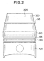
- a ring guide 300 which is a jig for fitting the inner ring 30 into the ring groove 120 while enlarging the inner ring 30, is carried out.
- Fig. 2 shows a state where the ring guide 300 is attached to the piston 100.
- the ring guide 300 is composed of a cylindrical portion 310 and a truncated cone portion 320.
- the cylindrical portion 310 has such an inner diameter that the cylindrical portion 310 can be fitted onto the outer periphery of the piston 100.
- the cylindrical portion 310 has such a depth that when covering the piston 100 from the top portion thereof, the lower end of the cylindrical portion 310 is located at the center of a second land 125, which is located immediately above the second ring groove 120 into which the inner ring 30 is fitted.
- the top portion of the truncated cone portion 320 has such an outer diameter that the inner ring 30 is easily fitted onto the truncated cone portion 320.
- the outer diameter of the lower end portion of the truncated cone portion 320 is equal to that of the cylindrical portion 310.
- the thus-fitted ring guide 300 is used to fit the inner ring 30 into the second ring groove.
- This step is carried out using, for example, a ring-forcing jig 400 as shown in Fig. 3.
- the ring-forcing jig 400 causes three radially movable ring pieces 420 that are suitably supported by springs 410 to reciprocate along a column 430.
- the inner diameter of a circle composed of the three ring pieces 420 is larger than the outer diameter of the top portion of the truncated cone portion 320 of the ring guide 300, which is fitted onto the piston 100 that is suitably secured onto a work bench 440.
- the inner ring 30 When the inner ring 30 is forcibly fitted onto the ring guide 300, the inner ring 30 can be enlarged until the inner diameter thereof becomes equal to the outer diameter of the cylindrical portion 320 of the ring guide 300.
- the ring-forcing jig shown in the drawing is merely an example. Any type of jig can be used as long as it can forcibly fit the inner ring onto the ring guide as described above.
- the outer ring 20 is fitted onto the thus-fitted inner ring 30.
- the thus-fitted inner ring 30 is pressed outwards due to a tensile force of the coil expander 40, so that the inner ring 30 sticks out from the ring groove 120. Therefore, in the fourth step, the inner ring 30 is first forced inwards to ensure that it does not stick out from the ring groove 120, and the fitting operation of the outer ring 20 is then carried out.
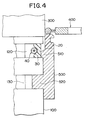
- Fig. 4 is a view from a direction perpendicular to the axis of the piston 100, showing how the inner ring 30 is pressed inwards.
- an inner ring pressing jig 500 is divided into two portions when viewed from the piston-axis direction.
- the inner ring pressing jig 500 has an inner ring pressing portion 510 for pressing the inner ring 30 and a positioning portion 520 for positioning the inner ring pressing portion 510 at a predetermined position.
- the positioning portion 520 is tightly fitted into an oil ring groove 130, which is located below the second ring groove 120 into which the inner ring 30 is fitted.
- the inner ring pressing portion 510 presses the inner ring 30 inwards such that the outermost portion of the inner ring 30 is located inwardly of the outer circumference of the piston 100 when the positioning portion 520 is tightly fitted into the oil ring groove 130.
- the outer ring 20 is pressed downwards using the ring guide 300 and the ring-forcing jig 400.
- the outer ring 20 comes into contact with an upper face 510 of the inner ring pressing jig 500, the inner ring pressing jig 500 is removed. Thereafter, the outer ring 20 is pressed further downwards using the ring-forcing jig 400 until the outer ring 20 is fitted onto the inner ring 30.
- the piston ring structural body 10 can be fitted into the second ring groove 120 of the piston 100 easily and reliably.
- the piston ring structural body 10 has a construction wherein the outer ring 20 continuously formed of polyimide without being provided with an abutment is pressed radially outwards by the steel coil expander 40 via the inner ring 30 continuously formed of PTFE without being provided with an abutment.
- the piston ring structural body is used as a second ring that is fitted into the second ring groove, which is located at the second closest position to the top portion of the piston.
- the piston ring structural body can also be used as a ring other than the second ring, for example, a sealing ring of the piston.
- the inner ring of the aforementioned embodiment is more susceptible to deformation at a high temperature, the sealability around the ring groove is ensured and the coil expander can suitably apply a tensile force to the outer ring.
- the outer ring is unlikely to be deformed even at a high temperature, so that the outer ring smoothly slides on the cylinder wall surface without causing any damage to the sealability between itself and the cylinder wall surface. Accordingly, it is possible to obtain a piston ring structural body that resists well a possible deterioration of sealability, exhibits high durability and inhibits an increase in friction loss by reducing a pressing force applied to the cylinder wall due to a tensile force of the coil expander.
- the aforementioned mounting method makes it possible to fit the piston ring structural body into the piston ring groove easily and reliably.
Description
Claims (12)
- A piston ring structural body (10) fitted into a ring groove (120) of a piston (100), whereby:said piston ring structural body (10) includes an outer ring (20) continuously formed of a first resinous material without being provided with an abutment, an inner ring (30) continuously formed of a second resinous material without being provided with an abutment, and a ring tensile force applying member (40) for pressing said outer ring outwards in a radial direction of the piston via said inner ring; characterized in thatsaid first resinous material has a coefficient of thermal expansion and a breaking point that are lower than those of said second resinous material.
- The piston ring structural body according to claim 1, characterised in that the ring tensile force applying member (40) is a coil expander, which is a member composed of a metal wire wound like a coil.
- The piston ring structural body according to claim 1 or 2, characterised in that said first resinous material is polyimide and said second resinous material is polytetrafluoroethylene.
- The piston ring structural body according to claim 1, 2 or 3, characterised in that at least a lower face of said outer ring (20) is coated with any one of titanium nitride, chrome nitride and diamond-like carbon.
- The piston ring structural body according to one of claims 1 to 4, characterised in that at least an outer sliding face (24, 25) of said outer ring that is in sliding contact with a cylinder wall (200) is coated with one of titanium nitride, chrome nitride and diamond-like carbon.
- The piston ring structural body according to one of claims 1 to 5, characterised in that said piston ring structural body (10) is a second ring fitted into a ring groove that is located at the second closest position to a top portion of the piston.
- The piston ring structural body according to one of claims 1 to 6, characterised in:that an outside sliding face of the outer ring (20) that is in sliding contact with a cylinder wall (200) is divided in a top-to-bottom direction; andthat at least an upper edge of an uppermost sliding face is provided with a chamfer.
- The piston ring structural body according to claim 7,
characterised in that the lower sliding face (25), which is formed by dividing the outer sliding face of said outer ring (20), is provided with a chamfer (27) at an upper edge thereof,that the chamfer (26) of said upper sliding face is larger than the chamfer (27) of said lower sliding face, andthat said upper sliding face (24) is narrower than said lower sliding face (25) in the top-to-bottom direction. - The piston ring structural body according to one of claims 1 to 8, characterised in that a contact portion of the inner ring (30) that contacts the coil expander (40) is provided with an upper inclined face extending radially inwards and upwards and a lower inclined face extending radially inwards and downwards.
- The piston ring structural body according to claim 9, characterised in that angles of inclination of the upper and lower inclined faces with respect to a plane where the coil expander (40) is disposed, are within the range of 30° to 60°.
- A method of mounting a piston ring structural body, including the steps of:fitting a coil expander (40) into a piston ring groove (120);covering a piston (100) from a top side thereof with a ring guide (300) having a truncated cone portion that is enlarged toward a cylindrical portion adapted to an outer circumference of the piston, such that a lower end of the cylindrical portion is located close to a centre of a land (125) that is located immediately above said piston ring groove (120);fitting an inner ring (30) continuously formed of a second resinous material without being provided with an abutment into the piston ring groove (120), using the truncated cone portion of said ring guide; andfitting an outer ring (20) continuously formed of a first resinous material without being provided with an abutment into the piston ring groove (120), using the truncated cone portion of said ring guide, in a state where the inner ring (30) thus fitted into the piston ring groove (120) and pressed outwards by the coil expander (40) is pressed radially inwards by an inner ring pressing jig (500) so as to prevent an outermost portion of the inner ring from projecting from the piston ring groove.
- The method according to claim 11, wherein said inner ring pressing jig (500) defines a pressing portion for pressing the inner ring radially inwards and a fit portion that is fitted into another ring groove to be positioned therein.
Applications Claiming Priority (2)
| Application Number | Priority Date | Filing Date | Title |
|---|---|---|---|
| JP03922698A JP3324980B2 (en) | 1998-02-20 | 1998-02-20 | Assembling method of piston ring structure |
| JP3922698 | 1998-02-20 |
Publications (3)
| Publication Number | Publication Date |
|---|---|
| EP0937921A2 EP0937921A2 (en) | 1999-08-25 |
| EP0937921A3 EP0937921A3 (en) | 2000-03-22 |
| EP0937921B1 true EP0937921B1 (en) | 2003-11-05 |
Family
ID=12547227
Family Applications (1)
| Application Number | Title | Priority Date | Filing Date |
|---|---|---|---|
| EP99400047A Expired - Lifetime EP0937921B1 (en) | 1998-02-20 | 1999-01-08 | Piston ring and method of mounting the piston ring |
Country Status (6)
| Country | Link |
|---|---|
| US (1) | US6283478B1 (en) |
| EP (1) | EP0937921B1 (en) |
| JP (1) | JP3324980B2 (en) |
| KR (1) | KR100304202B1 (en) |
| CN (1) | CN1108443C (en) |
| DE (1) | DE69912490T2 (en) |
Cited By (1)
| Publication number | Priority date | Publication date | Assignee | Title |
|---|---|---|---|---|
| DE102004041235A1 (en) * | 2004-08-26 | 2006-03-02 | Ina-Schaeffler Kg | Wear resistant coating and method of making same |
Families Citing this family (21)
| Publication number | Priority date | Publication date | Assignee | Title |
|---|---|---|---|---|
| KR100447455B1 (en) * | 2001-07-30 | 2004-09-07 | 삼영기계주식회사 | Piston for two cycle engine |
| US20040198464A1 (en) * | 2003-03-04 | 2004-10-07 | Jim Panian | Wireless communication systems for vehicle-based private and conference calling and methods of operating same |
| US20040258547A1 (en) * | 2003-04-02 | 2004-12-23 | Kurt Burger | Pump piston and/or elements sealing the pump piston, in particular a sealing ring of elastomeric material, and a device and method for coating an object of elastomeric material |
| US7156056B2 (en) * | 2004-06-10 | 2007-01-02 | Achates Power, Llc | Two-cycle, opposed-piston internal combustion engine |
| US7360511B2 (en) | 2004-06-10 | 2008-04-22 | Achates Power, Inc. | Opposed piston engine |
| DE102007005061B4 (en) * | 2007-01-26 | 2009-04-09 | Lsm Sondermaschinen Gmbh | Method and device for mounting at least one piston ring on a piston |
| US8251373B2 (en) * | 2009-07-17 | 2012-08-28 | GM Global Technology Operations LLC | Seal performance for hydrogen storage and supply systems |
| US10036471B2 (en) | 2009-11-18 | 2018-07-31 | Achates Power, Inc. | Ported engine constructions with low-tension compression seals |
| JP5557562B2 (en) | 2010-03-10 | 2014-07-23 | Tpr株式会社 | Combination oil ring |
| US20120085313A1 (en) * | 2010-10-12 | 2012-04-12 | Reisser Heinz-Gustav A | Piston-head design for use in an internal combustion engine |
| BRPI1102336B1 (en) * | 2011-05-27 | 2021-01-12 | Mahle Metal Leve S/A | element provided with at least one sliding surface for use in a combustion engine |
| US9206899B2 (en) * | 2013-03-15 | 2015-12-08 | Fisher Controls International Llc | Pistons |
| US9903474B2 (en) * | 2013-03-27 | 2018-02-27 | Kabushiki Kaisha Riken | Seal device |
| DE102014217392A1 (en) * | 2014-09-01 | 2016-03-03 | Trelleborg Sealing Solutions Germany Gmbh | Sealing arrangement with druckaktivierbarem biasing element |
| CN106078612A (en) * | 2016-08-16 | 2016-11-09 | 安庆瑞莱博汽车配件有限公司 | The erecting device that a kind of automobile piston rings is special |
| CN106181876A (en) * | 2016-08-16 | 2016-12-07 | 安庆瑞莱博汽车配件有限公司 | A kind of portable piston ring erecting device |
| CN108687714B (en) * | 2018-07-19 | 2023-10-20 | 侯马经济开发区日祥科技有限公司 | High-efficient piston ring mounting tool |
| CN108747307B (en) * | 2018-07-28 | 2023-10-10 | 蚌埠液力机械有限公司 | Semi-automatic assembly device and assembly method for piston body sealing ring of hydraulic cylinder |
| CN109732527B (en) * | 2019-03-11 | 2024-01-19 | 中铁工程装备集团有限公司 | Strip type sealing installation device |
| CN110052997A (en) * | 2019-05-08 | 2019-07-26 | 成立航空技术有限公司 | A kind of spring fitting device of new structure bolt |
| JP2023161843A (en) * | 2022-04-26 | 2023-11-08 | トヨタ自動車株式会社 | Ring attachment fixture and ring attachment method |
Family Cites Families (12)
| Publication number | Priority date | Publication date | Assignee | Title |
|---|---|---|---|---|
| US3806137A (en) * | 1970-03-04 | 1974-04-23 | Ramsey Corp | Resilient plastic piston ring |
| DE2329504A1 (en) * | 1972-06-22 | 1974-01-31 | Strazdins Atis | SEAL FOR CYLINDER AND PISTON MOVING BACK AND BACK IN CYLINDER |
| JPS57148036A (en) | 1981-03-07 | 1982-09-13 | Nippon Soken Inc | Automatically stopping device of warm-up operation for internal combustion engine |
| DE3325015C1 (en) * | 1983-07-11 | 1984-08-23 | Goetze Ag, 5093 Burscheid | Sealing ring |
| JPS61136060A (en) | 1984-12-03 | 1986-06-23 | Toshiba Mach Co Ltd | Piston ring |
| DK157947C (en) * | 1987-03-20 | 1990-09-10 | Shamban W S Europ | COMBINATION SEAL FOR SEAL BETWEEN TWO MACHINE ELEMENTS |
| JP2553203B2 (en) * | 1988-10-31 | 1996-11-13 | 株式会社東芝 | Cryogenic refrigerator |
| US5303465A (en) * | 1992-04-27 | 1994-04-19 | Honda Giken Kogyo Kabushiki Kaisha | Method of assembling piston ring and method of assembling set oil ring and apparatus for assembling set oil ring |
| CN1068388C (en) * | 1994-07-30 | 2001-07-11 | 株式会社理研 | Sliding material and method for preparing thereof |
| JP3413991B2 (en) * | 1994-10-14 | 2003-06-09 | 日立工機株式会社 | Driving machine piston device |
| JP3244396B2 (en) | 1995-02-20 | 2002-01-07 | トヨタ自動車株式会社 | piston ring |
| JPH09280373A (en) | 1996-04-17 | 1997-10-28 | Toyota Motor Corp | Piston ring |
-
1998
- 1998-02-20 JP JP03922698A patent/JP3324980B2/en not_active Expired - Fee Related
-
1999
- 1999-01-08 EP EP99400047A patent/EP0937921B1/en not_active Expired - Lifetime
- 1999-01-08 DE DE69912490T patent/DE69912490T2/en not_active Expired - Fee Related
- 1999-02-04 US US09/244,849 patent/US6283478B1/en not_active Expired - Fee Related
- 1999-02-11 CN CN99102121A patent/CN1108443C/en not_active Expired - Fee Related
- 1999-02-19 KR KR1019990005584A patent/KR100304202B1/en not_active IP Right Cessation
Cited By (1)
| Publication number | Priority date | Publication date | Assignee | Title |
|---|---|---|---|---|
| DE102004041235A1 (en) * | 2004-08-26 | 2006-03-02 | Ina-Schaeffler Kg | Wear resistant coating and method of making same |
Also Published As
| Publication number | Publication date |
|---|---|
| CN1226633A (en) | 1999-08-25 |
| EP0937921A3 (en) | 2000-03-22 |
| EP0937921A2 (en) | 1999-08-25 |
| US6283478B1 (en) | 2001-09-04 |
| DE69912490T2 (en) | 2004-08-26 |
| KR19990072777A (en) | 1999-09-27 |
| DE69912490D1 (en) | 2003-12-11 |
| JP3324980B2 (en) | 2002-09-17 |
| KR100304202B1 (en) | 2001-09-13 |
| JPH11230343A (en) | 1999-08-27 |
| CN1108443C (en) | 2003-05-14 |
Similar Documents
| Publication | Publication Date | Title |
|---|---|---|
| EP0937921B1 (en) | Piston ring and method of mounting the piston ring | |
| EP0937922B1 (en) | Sealing structure and mounting of piston ring for use in the sealing structure | |
| EP1557594B1 (en) | Oil ring | |
| JP3559417B2 (en) | Tensioning device for tensile means | |
| EP1099069B1 (en) | Unitized oil seal and method of manufacture | |
| US7036823B2 (en) | Side rail and combined oil control ring incorporated with the side rails for reduction of oil consumption | |
| US4045036A (en) | Piston oil control ring | |
| EP0937923B1 (en) | Piston equipped with piston ring | |
| US6454272B1 (en) | Sealing arrangement and a sealing member therefor | |
| JP7254836B2 (en) | Combined oil ring | |
| EP1196704B1 (en) | A sealing arrangement and a sealing member therefor | |
| US5901678A (en) | Guided piston for internal combustion engine | |
| US7188841B1 (en) | Secondary piston seal | |
| JP2006233823A (en) | Piston | |
| JP3244396B2 (en) | piston ring | |
| JP2000337509A (en) | Combination piston ring device | |
| JP3363788B2 (en) | piston ring | |
| WO1998016763A1 (en) | Gap-sealed piston ring | |
| JP5833867B2 (en) | piston | |
| JP2745150B2 (en) | Piston and piston ring assembly | |
| JPH10169778A (en) | Piston ring | |
| JPH094711A (en) | Pressure ring for engine | |
| CA1057327A (en) | Piston oil control ring | |
| JP4455337B2 (en) | Oil ring | |
| JPH08338530A (en) | Oil ring having expander |
Legal Events
| Date | Code | Title | Description |
|---|---|---|---|
| PUAI | Public reference made under article 153(3) epc to a published international application that has entered the european phase |
Free format text: ORIGINAL CODE: 0009012 |
|
| 17P | Request for examination filed |
Effective date: 19990128 |
|
| AK | Designated contracting states |
Kind code of ref document: A2 Designated state(s): DE FR GB |
|
| AX | Request for extension of the european patent |
Free format text: AL;LT;LV;MK;RO;SI |
|
| PUAL | Search report despatched |
Free format text: ORIGINAL CODE: 0009013 |
|
| AK | Designated contracting states |
Kind code of ref document: A3 Designated state(s): AT BE CH CY DE DK ES FI FR GB GR IE IT LI LU MC NL PT SE |
|
| AX | Request for extension of the european patent |
Free format text: AL;LT;LV;MK;RO;SI |
|
| RIC1 | Information provided on ipc code assigned before grant |
Free format text: 7F 16J 9/06 A, 7F 16J 9/28 B, 7B 25B 27/12 B |
|
| AKX | Designation fees paid |
Free format text: DE FR GB |
|
| GRAH | Despatch of communication of intention to grant a patent |
Free format text: ORIGINAL CODE: EPIDOS IGRA |
|
| GRAS | Grant fee paid |
Free format text: ORIGINAL CODE: EPIDOSNIGR3 |
|
| GRAA | (expected) grant |
Free format text: ORIGINAL CODE: 0009210 |
|
| AK | Designated contracting states |
Kind code of ref document: B1 Designated state(s): DE FR GB |
|
| REG | Reference to a national code |
Ref country code: GB Ref legal event code: FG4D |
|
| REF | Corresponds to: |
Ref document number: 69912490 Country of ref document: DE Date of ref document: 20031211 Kind code of ref document: P |
|
| ET | Fr: translation filed | ||
| PLBE | No opposition filed within time limit |
Free format text: ORIGINAL CODE: 0009261 |
|
| STAA | Information on the status of an ep patent application or granted ep patent |
Free format text: STATUS: NO OPPOSITION FILED WITHIN TIME LIMIT |
|
| 26N | No opposition filed |
Effective date: 20040806 |
|
| PGFP | Annual fee paid to national office [announced via postgrant information from national office to epo] |
Ref country code: DE Payment date: 20060105 Year of fee payment: 8 |
|
| PGFP | Annual fee paid to national office [announced via postgrant information from national office to epo] |
Ref country code: FR Payment date: 20060110 Year of fee payment: 8 |
|
| PG25 | Lapsed in a contracting state [announced via postgrant information from national office to epo] |
Ref country code: DE Free format text: LAPSE BECAUSE OF NON-PAYMENT OF DUE FEES Effective date: 20070801 |
|
| GBPC | Gb: european patent ceased through non-payment of renewal fee |
Effective date: 20070108 |
|
| REG | Reference to a national code |
Ref country code: FR Ref legal event code: ST Effective date: 20070930 |
|
| PG25 | Lapsed in a contracting state [announced via postgrant information from national office to epo] |
Ref country code: GB Free format text: LAPSE BECAUSE OF NON-PAYMENT OF DUE FEES Effective date: 20070108 |
|
| PG25 | Lapsed in a contracting state [announced via postgrant information from national office to epo] |
Ref country code: FR Free format text: LAPSE BECAUSE OF NON-PAYMENT OF DUE FEES Effective date: 20070131 |
|
| PGFP | Annual fee paid to national office [announced via postgrant information from national office to epo] |
Ref country code: GB Payment date: 20060104 Year of fee payment: 8 |