EP0937366B1 - Method of combining several signals, and base station - Google Patents
Method of combining several signals, and base station Download PDFInfo
- Publication number
- EP0937366B1 EP0937366B1 EP97911251A EP97911251A EP0937366B1 EP 0937366 B1 EP0937366 B1 EP 0937366B1 EP 97911251 A EP97911251 A EP 97911251A EP 97911251 A EP97911251 A EP 97911251A EP 0937366 B1 EP0937366 B1 EP 0937366B1
- Authority
- EP
- European Patent Office
- Prior art keywords
- signals
- base station
- carrier waves
- antenna
- modulating
- Prior art date
- Legal status (The legal status is an assumption and is not a legal conclusion. Google has not performed a legal analysis and makes no representation as to the accuracy of the status listed.)
- Expired - Lifetime
Links
Images
Classifications
-
- H—ELECTRICITY
- H04—ELECTRIC COMMUNICATION TECHNIQUE
- H04B—TRANSMISSION
- H04B1/00—Details of transmission systems, not covered by a single one of groups H04B3/00 - H04B13/00; Details of transmission systems not characterised by the medium used for transmission
- H04B1/69—Spread spectrum techniques
- H04B1/713—Spread spectrum techniques using frequency hopping
- H04B1/7136—Arrangements for generation of hop frequencies, e.g. using a bank of frequency sources, using continuous tuning or using a transform
-
- H—ELECTRICITY
- H04—ELECTRIC COMMUNICATION TECHNIQUE
- H04B—TRANSMISSION
- H04B1/00—Details of transmission systems, not covered by a single one of groups H04B3/00 - H04B13/00; Details of transmission systems not characterised by the medium used for transmission
- H04B1/69—Spread spectrum techniques
- H04B1/713—Spread spectrum techniques using frequency hopping
Definitions
- the invention relates to a method of combining several signals, the method being used at base stations of a radio network, carrier waves and signals being generated at the base station, the signals being used for modulating the generated carrier waves, the base station comprising an antenna for transmitting the modulated signals to a carrier wave.
- the invention further relates to a base station used for combining several signals in a radio network, the base station comprising an antenna, modulating means for generating and modulating carrier waves, and transmitters for generating signals for modulating the generated carrier waves, the signals being transmitted modulated to a carrier wave using the antenna.
- the base station antenna transmits several signals generated by base station transmitters.
- the signals modulate the carrier wave and the carrier waves are transmitted to the radio path using a radio channel.
- the signal perceived in the receiver is the sum of signals propagated on several routes and reflected off the obstacles, and that are of different phases.
- the sum of several signals of different phases follows the Rayleigh distribution, when the phases are randomly distributed.
- the fading of the signal also depends on the frequency of the signal.
- Frequency hopping means that the transmission frequency used on a connection is changed at regular intervals. Due to frequency hopping, transfer quality can be improved especially in such cases, in which a subscriber terminal moves very slowly or is stationary, which is often the case when e.g. a mobile phone is used.
- the method is useful in scattering the interference caused by a radio connection over several frequencies, the momentary interference at a particular frequency remaining small.
- the frequencies used should be more than four.
- narrowband transmitter combiners are commonly used at base stations.
- the narrowband combiners whose function is to combine several transmitters with one antenna, restrict the number of frequencies used in frequency hopping to the number of actual transceiver units and combiner filters.
- a base station using three transceiver units and three combiner filters enables the use of three frequencies in frequency hopping.
- Narrowband transmitter combiners are large and complex components because they have to be able to be tuned. Wideband combiners that do not require such a tuning have also been generated. Wideband combiners together with frequency hopping synthesizers do not restrict the number of frequencies used. A problem with wideband combiners is, however, that combiner attenuations become extremely large compared with narrowband combiners, when more than two transmitters are combined with the same wideband combiner. Hence, it has not been possible to use wideband combiners at base stations, from which a large traffic capacity is required, but narrowband combiners have had to be used. The implementation of frequency hopping at these base stations has thus been inadequate.
- EP-A-681374 there is depicted a channel selective repeater for digital radio networks such as GSM, DCS 1800 and PCS 1900.
- the repeater is designed to optimise the operation degree which means that a higher output power can be achieved.
- An object of the present invention is to allow several transmitters to be combined into the same antenna in such a manner that frequency hopping is easy to implement.
- a further object of the invention is to implement a base station, in which such an amplifier that is easy to implement is used to amplify the carrier wave.
- the base station of the invention is characterized in that the modulating means are adapted such that two or more of said signals modulate one of said carrier waves, and that the base station comprises means for amplifying the carrier waves modulated by the signals, and means for passively combining in wideband the output signals of said amplifying means to the same antenna in a way to enable the use of frequency hopping.
- the carrier wave is modulated by two different signals and several carrier waves are combined in such a manner that the carrier waves can be transmitted using one antenna.
- the method preferably uses a DDS modulating method, due to which e.g. two modulating signals can be easily implemented.
- the carrier waves are amplified with an amplifier, whose linearity requirements are easy to implement.
- combining the carrier waves to one antenna is carried out in wideband enabling the use of frequency hopping.
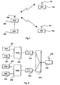
- FIG. 1 shows a cellular radio system, in which the solution of the invention can be used.
- the cellular radio system comprises in each cell at least one base station 200 and a number of subscriber terminals 100.
- the subscriber terminals 100 comprise an antenna 101 and the base station comprises an antenna 206 for transmitting and to receiving signals.
- the base station 200 communicates with the subscriber terminals 100 within its area.
- the connection between the base station 200 and the base station controller 300 is implemented e.g. using a PCM technique.
- the base station 200 and the subscriber terminal 100 operate as transceivers.
- the base station 200 of the invention can preferably be used in e.g. digital GSM and DCS cellular radio systems, in which frequency hopping technique is used.
- the base station 200 and the subscriber terminals 100 transmit signals to one another using a carrier wave.
- a transmitted signal is used for establishing a connection between the base station 200 and the subscriber terminal 100.
- the transmitted signal comprises information.
- the signal is modulated before transmission.
- a carrier wave is modulated with e.g. a digital signal.
- reception the carrier wave is demodulated, whereby a signal comprising information is separated from the carrier wave.
- FIG. 2 a block diagram illustrates the structure of the base station 200 in accordance with one preferred embodiment of the invention.
- the base station 200 of the invention comprises a number of transmitters 201, modulating means 202 and an antenna 206.
- the transmitters 201 are in connection with the modulating means 202.
- the modulating means 202 generate and modulate a carrier wave signal.
- the base station 200 transmits a signal modulated to the carrier wave to the subscriber terminals 100.
- the base station 200 further comprises means 203 for amplifying the signal and means 204 for combining the transmitters 201 with the antenna 206.
- the base station 200 comprises an antenna filter 205 connected between the means 204 and the antenna 206.
- the antenna filter 205 functions as a duplex filter which is needed when the same physical antenna is used as a transmitting and a receiving antenna.
- the transmitters 201 transmit signals to the modulating means 202, the signals modulating the carrier wave generated in the modulating means 202.
- the modulating means 202 use preferably the DDS (Direct Digital Synthesis) method by which it is possible to easily implement various modulation methods.
- DDS Direct Digital Synthesis
- an output frequency is digitally generated from a reference frequency.
- the DDS method is very well adapted for use especially in cellular radio systems using frequency hopping and the spread-spectrum technique.
- the modulating means 202 modulate the carrier wave using a signal generated by two transmitters 201.
- the modulating means 202 preferably modulate two or several signals to their own carrier wave.
- the carrier wave is connected to the means 203 that function as an amplifier.
- the means 203 amplify the carrier wave in such a manner that the carrier wave propagates far enough from the base station 200 to the subscriber terminals 100.
- the means 203 have preferably been implemented as half linear, whereby the linearity requirements of the means 203 are held within reasonable limits compared with e.g. the linearity requirements of a linear amplifier. In addition, it is fairly easy to implement a half linear amplifier, and a good performance is obtained for said amplifier.
- the carrier wave is connected through the antenna filter 205 to the antenna 206. The carrier wave is then transmitted to the subscriber terminals 100 within the coverage area of the base station 200.
- each carrier wave preferably comprises a signal generated by two transmitters 201.
- Several generated carrier waves are combined in the means 204, whereby the signals generated by several transmitters 201 are connected to the same antenna 206.
- the means 204 passively combine the carrier waves modulated by the signals using one antenna 206.
- the means 204 are preferably implemented using a wideband combiner. Said combiner enables the use of frequency hopping in a cellular radio network.
- the transmitter 201 At the base station 200 of the invention several transmitters 201 are connected to one antenna 206.
- the transmitter 201 generates a signal that modulates the carrier wave.
- the carrier wave is modulated by two different signals.
- the modulated carrier wave is amplified, and if several carrier waves are generated, the carrier waves are combined in e.g. a hybrid combiner 204.
- the combiner 204 is arranged to combine several carrier waves for transmission to the radio path through one antenna 206.
Landscapes
- Engineering & Computer Science (AREA)
- Computer Networks & Wireless Communication (AREA)
- Signal Processing (AREA)
- Mobile Radio Communication Systems (AREA)
- Air Bags (AREA)
Abstract
Description
- The invention relates to a method of combining several signals, the method being used at base stations of a radio network, carrier waves and signals being generated at the base station, the signals being used for modulating the generated carrier waves, the base station comprising an antenna for transmitting the modulated signals to a carrier wave.
- The invention further relates to a base station used for combining several signals in a radio network, the base station comprising an antenna, modulating means for generating and modulating carrier waves, and transmitters for generating signals for modulating the generated carrier waves, the signals being transmitted modulated to a carrier wave using the antenna.
- In cellular radio systems, such as GSM/DCS systems, the base station antenna transmits several signals generated by base station transmitters. The signals modulate the carrier wave and the carrier waves are transmitted to the radio path using a radio channel. There are various methods of transmitting signals generated by transmitters to the radio path using only one antenna. It is common to use different combiners for combining several transmitters with the same antenna at the base station.
- Very often a transmitting and a receiving antenna do not have a line of sight, but there are obstacles caused by terrain or buildings. Thus the signal perceived in the receiver is the sum of signals propagated on several routes and reflected off the obstacles, and that are of different phases. The sum of several signals of different phases follows the Rayleigh distribution, when the phases are randomly distributed. The fading of the signal also depends on the frequency of the signal. The frequency selective fading of a signal is one of the reasons for bringing frequency hopping technique into use in digital cellular radio networks. Frequency hopping means that the transmission frequency used on a connection is changed at regular intervals. Due to frequency hopping, transfer quality can be improved especially in such cases, in which a subscriber terminal moves very slowly or is stationary, which is often the case when e.g. a mobile phone is used. In addition to the frequency diversity brought about by frequency hopping, the method is useful in scattering the interference caused by a radio connection over several frequencies, the momentary interference at a particular frequency remaining small.
- In order to gain advantage from frequency hopping in the digital GSM and DCS systems, the frequencies used should be more than four. Currently narrowband transmitter combiners are commonly used at base stations. The narrowband combiners, whose function is to combine several transmitters with one antenna, restrict the number of frequencies used in frequency hopping to the number of actual transceiver units and combiner filters. Thus for example a base station using three transceiver units and three combiner filters enables the use of three frequencies in frequency hopping.
- Narrowband transmitter combiners are large and complex components because they have to be able to be tuned. Wideband combiners that do not require such a tuning have also been generated. Wideband combiners together with frequency hopping synthesizers do not restrict the number of frequencies used. A problem with wideband combiners is, however, that combiner attenuations become extremely large compared with narrowband combiners, when more than two transmitters are combined with the same wideband combiner. Hence, it has not been possible to use wideband combiners at base stations, from which a large traffic capacity is required, but narrowband combiners have had to be used. The implementation of frequency hopping at these base stations has thus been inadequate.
- Alternatively, it has also been possible to combine the modulated carrier waves before the final amplification of the signal. A linear amplifier in particular has been used as the amplifier. A disadvantage of the linear amplifier has, however, been its difficult technical implementation, as the linearity requirements of the amplifier have been high. Furthermore, the performance of linear amplifiers has been poor.
- In
EP-A-681374 - In "Satellite communication systems", Evans B.G. et al, 1987, chapter 14, pages 230-250, there are depicted communication repeaters. Processing repeaters are used to provide enhanced performance characteristics such as increased immunity to interfering signals. The purpose and design features of repeaters are outlined in the book in question.
- An object of the present invention is to allow several transmitters to be combined into the same antenna in such a manner that frequency hopping is easy to implement. A further object of the invention is to implement a base station, in which such an amplifier that is easy to implement is used to amplify the carrier wave.
- This is achieved with the method set forth in the preamble characterized in that two or more signals, each signal being generated by a respective transmitter, modulate one of said carrier waves, and then the carrier waves modulated by the signals are amplified with amplifiers, and the output signals of the amplifiers are passively combined in wideband to the same antenna in a way to enable the use of frequency hopping.
- The base station of the invention is characterized in that the modulating means are adapted such that two or more of said signals modulate one of said carrier waves, and that the base station comprises means for amplifying the carrier waves modulated by the signals, and means for passively combining in wideband the output signals of said amplifying means to the same antenna in a way to enable the use of frequency hopping.
- Great advantages are achieved with the method of the invention. In this method the carrier wave is modulated by two different signals and several carrier waves are combined in such a manner that the carrier waves can be transmitted using one antenna. The method preferably uses a DDS modulating method, due to which e.g. two modulating signals can be easily implemented. Furthermore, the carrier waves are amplified with an amplifier, whose linearity requirements are easy to implement. In addition, combining the carrier waves to one antenna is carried out in wideband enabling the use of frequency hopping.
- The preferred embodiments of the method of the invention are also disclosed in the enclosed dependent claims and the preferred embodiments of the base station of the invention are disclosed in the enclosed dependent claims.
- In the following the invention will be described in greater detail with reference to examples in the accompanying drawings, in which
-
Figure 1 shows a cellular radio system, in which the base station of the invention can be used, and -
Figure 2 shows a block diagram illustrating the structure of the base station of the invention. -
Figure 1 shows a cellular radio system, in which the solution of the invention can be used. The cellular radio system comprises in each cell at least onebase station 200 and a number ofsubscriber terminals 100. Thesubscriber terminals 100 comprise anantenna 101 and the base station comprises anantenna 206 for transmitting and to receiving signals. Thebase station 200 communicates with thesubscriber terminals 100 within its area. There is also a connection from thebase station 200 to abase station controller 300, which controls the operation of thebase station 200 and connects the calls of thesubscriber terminals 100 further to a fixed network or to other parts of the system. The connection between thebase station 200 and thebase station controller 300 is implemented e.g. using a PCM technique. InFigure 1 thebase station 200 and thesubscriber terminal 100 operate as transceivers. Thebase station 200 of the invention can preferably be used in e.g. digital GSM and DCS cellular radio systems, in which frequency hopping technique is used. - In the cellular radio system, shown in
Figure 1 , thebase station 200 and thesubscriber terminals 100 transmit signals to one another using a carrier wave. A transmitted signal is used for establishing a connection between thebase station 200 and thesubscriber terminal 100. The transmitted signal comprises information. The signal is modulated before transmission. In modulation, a carrier wave is modulated with e.g. a digital signal. In reception, the carrier wave is demodulated, whereby a signal comprising information is separated from the carrier wave. - In
Figure 2 a block diagram illustrates the structure of thebase station 200 in accordance with one preferred embodiment of the invention. Thebase station 200 of the invention comprises a number oftransmitters 201, modulating means 202 and anantenna 206. In the solution shown inFigure 2 , thetransmitters 201 are in connection with the modulating means 202. The modulating means 202 generate and modulate a carrier wave signal. Thebase station 200 transmits a signal modulated to the carrier wave to thesubscriber terminals 100. Thebase station 200 further comprisesmeans 203 for amplifying the signal and means 204 for combining thetransmitters 201 with theantenna 206. Furthermore, thebase station 200 comprises anantenna filter 205 connected between themeans 204 and theantenna 206. Theantenna filter 205 functions as a duplex filter which is needed when the same physical antenna is used as a transmitting and a receiving antenna. - In the solution shown in
Figure 2 , there are preferably twotransmitters 201 in connection with the same modulating means 202. Thetransmitters 201 transmit signals to the modulating means 202, the signals modulating the carrier wave generated in the modulating means 202. When modulating the carrier wave, the modulating means 202 use preferably the DDS (Direct Digital Synthesis) method by which it is possible to easily implement various modulation methods. In the DDS method an output frequency is digitally generated from a reference frequency. The DDS method is very well adapted for use especially in cellular radio systems using frequency hopping and the spread-spectrum technique. Thus, in the solution shown inFigure 2 , the modulating means 202 modulate the carrier wave using a signal generated by twotransmitters 201. The modulating means 202 preferably modulate two or several signals to their own carrier wave. - After modulation, the carrier wave is connected to the
means 203 that function as an amplifier. The means 203 amplify the carrier wave in such a manner that the carrier wave propagates far enough from thebase station 200 to thesubscriber terminals 100. The means 203 have preferably been implemented as half linear, whereby the linearity requirements of themeans 203 are held within reasonable limits compared with e.g. the linearity requirements of a linear amplifier. In addition, it is fairly easy to implement a half linear amplifier, and a good performance is obtained for said amplifier. After amplification, the carrier wave is connected through theantenna filter 205 to theantenna 206. The carrier wave is then transmitted to thesubscriber terminals 100 within the coverage area of thebase station 200. - If the
base station 200 comprises more than twotransmitters 201, more carrier waves are generated at thebase station 200. Such a number of carrier waves is generated that each carrier wave preferably comprises a signal generated by twotransmitters 201. Several generated carrier waves are combined in themeans 204, whereby the signals generated byseveral transmitters 201 are connected to thesame antenna 206. The means 204 passively combine the carrier waves modulated by the signals using oneantenna 206. The means 204 are preferably implemented using a wideband combiner. Said combiner enables the use of frequency hopping in a cellular radio network. - At the
base station 200 of the inventionseveral transmitters 201 are connected to oneantenna 206. Thetransmitter 201 generates a signal that modulates the carrier wave. Preferably the carrier wave is modulated by two different signals. The modulated carrier wave is amplified, and if several carrier waves are generated, the carrier waves are combined in e.g. ahybrid combiner 204. Thecombiner 204 is arranged to combine several carrier waves for transmission to the radio path through oneantenna 206. - Even though the invention has been explained in the above with reference to the example in accordance with the accompanying drawings, it is obvious that the invention is not restricted to it but can be modified in various ways within the scope of the inventive idea disclosed in the attached claims.
Claims (4)
- A method of combining several signals, the method being used at a base station (200) of a radio network, carrier waves and signals being generated at the base station, the signals being used for modulating the generated carrier waves, the base station (200) comprising an antenna (206) for transmitting the modulated signals to a carrier wave, characterized in that two or more signals, each signal being generated by a respective transmitter, modulate one of said carrier waves, and then the carrier waves mod u-lated by the signals are amplified with amplifiers, and the output signals of the amplifiers are passively combined in wideband to the same antenna (206) to enable the use of frequency hopping.
- A method as claimed in claim 1, characterized in that a Direct Digital Synthesis method or a method corresponding to the Direct Digital Synthesis method is used in the modulation.
- A base station (200) used for combining several signals in a radio network, the base station (200) comprising an antenna (206), modulating means (202) for generating and modulating carrier waves, and transmitters (201) for generating signals for modulating the generated carrier waves, the signals being transmitted modulated to a carrier wave using the antenna (206), characterized in that the modulating means (202) are adapted such that two or more of said signals modulate one of said carrier waves, and that the base station comprises means (203) for amplifying the carrier waves modulated by the signals, and means (204) for passively combining in wideband the output signals of means (203) to the same antenna (206) to enable the use of frequency hopping.
- A base station (200) as claimed in claim 3, characterized in that the modulating means (202) use a Direct Digital Synthesis method or a method corresponding to the Direct Digital Synthesis method in modulating the carrier wave.
Applications Claiming Priority (3)
| Application Number | Priority Date | Filing Date | Title |
|---|---|---|---|
| FI964362A FI105511B (en) | 1996-10-29 | 1996-10-29 | Procedure for combining multiple signals and base station |
| FI964362 | 1996-10-29 | ||
| PCT/FI1997/000658 WO1998019465A2 (en) | 1996-10-29 | 1997-10-28 | Method of combining several signals, and base station |
Publications (2)
| Publication Number | Publication Date |
|---|---|
| EP0937366A2 EP0937366A2 (en) | 1999-08-25 |
| EP0937366B1 true EP0937366B1 (en) | 2008-04-23 |
Family
ID=8546957
Family Applications (1)
| Application Number | Title | Priority Date | Filing Date |
|---|---|---|---|
| EP97911251A Expired - Lifetime EP0937366B1 (en) | 1996-10-29 | 1997-10-28 | Method of combining several signals, and base station |
Country Status (10)
| Country | Link |
|---|---|
| US (1) | US6317610B1 (en) |
| EP (1) | EP0937366B1 (en) |
| JP (1) | JP2001503220A (en) |
| CN (1) | CN1138430C (en) |
| AT (1) | ATE393547T1 (en) |
| AU (1) | AU727274B2 (en) |
| DE (1) | DE69738651T2 (en) |
| FI (1) | FI105511B (en) |
| NO (1) | NO992043D0 (en) |
| WO (1) | WO1998019465A2 (en) |
Families Citing this family (7)
| Publication number | Priority date | Publication date | Assignee | Title |
|---|---|---|---|---|
| EP1096818A1 (en) * | 1999-10-29 | 2001-05-02 | TELEFONAKTIEBOLAGET LM ERICSSON (publ) | Base station with a first and a second base unit |
| EP1182786B1 (en) * | 2000-08-21 | 2006-11-08 | Lucent Technologies Inc. | Transmission and reception device for base stations |
| FR2832269B1 (en) * | 2001-11-12 | 2004-11-19 | Evolium Sas | METHOD FOR OPTIMIZING THE EFFICIENCY OF AN AMPLIFIER FOR SIMULTANEOUSLY AMPLIFYING MULTIPLE MODULATED CARRIERS |
| US7302237B2 (en) * | 2002-07-23 | 2007-11-27 | Mercury Computer Systems, Inc. | Wideband signal generators, measurement devices, methods of signal generation, and methods of signal analysis |
| DE602004021178D1 (en) * | 2004-06-24 | 2009-07-02 | Verigy Pte Ltd Singapore | Clock synthesis per pin |
| JP5096443B2 (en) * | 2009-12-07 | 2012-12-12 | 株式会社エヌ・ティ・ティ・ドコモ | Wireless communication device |
| CN108512571B (en) * | 2018-02-13 | 2020-05-12 | 北京航空航天大学 | Frequency hopping signal generating device |
Family Cites Families (10)
| Publication number | Priority date | Publication date | Assignee | Title |
|---|---|---|---|---|
| DE502811C (en) | 1927-03-15 | 1930-07-21 | Siemens Schuckertwerke Akt Ges | Device for exciting synchronously rotating machines |
| JPS60150344A (en) * | 1984-01-18 | 1985-08-08 | Nec Corp | Carrier communication system |
| US4941200A (en) * | 1987-08-03 | 1990-07-10 | Orion Industries, Inc. | Booster |
| US5163181A (en) * | 1988-10-21 | 1992-11-10 | Harris Corporation | Multiple rf signal amplification method and apparatus |
| US5214787A (en) | 1990-08-31 | 1993-05-25 | Karkota Jr Frank P | Multiple audio channel broadcast system |
| EP0622910B1 (en) | 1993-04-29 | 2003-06-25 | Ericsson Inc. | Time diversity transmission system for the reduction of adjacent channel interference in mobile telephone systems |
| EP0681374A1 (en) * | 1994-05-02 | 1995-11-08 | MIKOM GmbH | Repeater "On-frequency" with optimised efficiency for digital radio networks like GSM, DCS 1800, PCS 1900 and others |
| SE502811C2 (en) * | 1994-05-11 | 1996-01-22 | Allgon Ab | Repeater |
| US5585850A (en) | 1994-10-31 | 1996-12-17 | Schwaller; John | Adaptive distribution system for transmitting wideband video data over narrowband multichannel wireless communication system |
| US5559788A (en) | 1994-12-29 | 1996-09-24 | Unisys Corporation | Multiple channel quadrature communication system and method |
-
1996
- 1996-10-29 FI FI964362A patent/FI105511B/en active
-
1997
- 1997-10-28 AT AT97911251T patent/ATE393547T1/en not_active IP Right Cessation
- 1997-10-28 WO PCT/FI1997/000658 patent/WO1998019465A2/en active IP Right Grant
- 1997-10-28 DE DE69738651T patent/DE69738651T2/en not_active Expired - Lifetime
- 1997-10-28 EP EP97911251A patent/EP0937366B1/en not_active Expired - Lifetime
- 1997-10-28 US US09/269,218 patent/US6317610B1/en not_active Expired - Lifetime
- 1997-10-28 JP JP10520091A patent/JP2001503220A/en active Pending
- 1997-10-28 CN CNB971992177A patent/CN1138430C/en not_active Expired - Lifetime
- 1997-10-28 AU AU48689/97A patent/AU727274B2/en not_active Ceased
-
1999
- 1999-04-28 NO NO992043A patent/NO992043D0/en not_active Application Discontinuation
Also Published As
| Publication number | Publication date |
|---|---|
| EP0937366A2 (en) | 1999-08-25 |
| FI105511B (en) | 2000-08-31 |
| AU4868997A (en) | 1998-05-22 |
| CN1138430C (en) | 2004-02-11 |
| DE69738651D1 (en) | 2008-06-05 |
| FI964362A0 (en) | 1996-10-29 |
| ATE393547T1 (en) | 2008-05-15 |
| US6317610B1 (en) | 2001-11-13 |
| JP2001503220A (en) | 2001-03-06 |
| NO992043L (en) | 1999-04-28 |
| CN1235741A (en) | 1999-11-17 |
| AU727274B2 (en) | 2000-12-07 |
| WO1998019465A2 (en) | 1998-05-07 |
| NO992043D0 (en) | 1999-04-28 |
| DE69738651T2 (en) | 2009-07-09 |
| WO1998019465A3 (en) | 1998-06-18 |
| FI964362A (en) | 1998-04-30 |
Similar Documents
| Publication | Publication Date | Title |
|---|---|---|
| AU688878B2 (en) | Method for realizing frequency hopping and a base station equipment | |
| US5809398A (en) | Channel selective repeater | |
| JPS6242537B2 (en) | ||
| EP0468688B1 (en) | Method and apparatus for providing wireless communications between remote locations | |
| JPS60140935A (en) | Method and device for connecting to moving subscriber | |
| US5553117A (en) | Vehicular communications system | |
| EP0884863A2 (en) | Distributed antenna for personal communication system | |
| EP0715786B1 (en) | Base station equipment using diversity reception | |
| EP0937366B1 (en) | Method of combining several signals, and base station | |
| JP2713161B2 (en) | Wireless communication system | |
| KR20020005312A (en) | Multi-channel repeater | |
| WO1998004053A2 (en) | Base station with antenna, including an amplifier, located at a distance from the station | |
| JPH06181452A (en) | Radio repeater | |
| KR100383722B1 (en) | Transmiting and receiving apparatus of mobile communicating system having coaxial cables | |
| JP3055613B2 (en) | Communication method of mobile terminal with repeater function | |
| MXPA04009950A (en) | Access method and umts repeater system with spectral exchange between umts wave frequencies. | |
| KR100348651B1 (en) | A service apparatus for different types of mobile phones | |
| KR20040039560A (en) | Portable repeater mounted on antenna of mobile communication terminal | |
| JPH05347580A (en) | Mobile communication system | |
| CS216567B1 (en) | Method of multiple duplex radiocommunication and device for executing the said method | |
| JPS5843636A (en) | Non-linear distortion compensating system of satellite communication | |
| KR19990007620A (en) | Booster circuit for wireless communication relay |
Legal Events
| Date | Code | Title | Description |
|---|---|---|---|
| PUAI | Public reference made under article 153(3) epc to a published international application that has entered the european phase |
Free format text: ORIGINAL CODE: 0009012 |
|
| 17P | Request for examination filed |
Effective date: 19990319 |
|
| AK | Designated contracting states |
Kind code of ref document: A2 Designated state(s): AT BE CH DE DK ES FI FR GB GR IE IT LI LU MC NL PT SE |
|
| RAP1 | Party data changed (applicant data changed or rights of an application transferred) |
Owner name: NOKIA NETWORKS OY |
|
| RAP1 | Party data changed (applicant data changed or rights of an application transferred) |
Owner name: NOKIA CORPORATION |
|
| 17Q | First examination report despatched |
Effective date: 20030904 |
|
| 17Q | First examination report despatched |
Effective date: 20030904 |
|
| GRAP | Despatch of communication of intention to grant a patent |
Free format text: ORIGINAL CODE: EPIDOSNIGR1 |
|
| GRAS | Grant fee paid |
Free format text: ORIGINAL CODE: EPIDOSNIGR3 |
|
| GRAA | (expected) grant |
Free format text: ORIGINAL CODE: 0009210 |
|
| AK | Designated contracting states |
Kind code of ref document: B1 Designated state(s): AT BE CH DE DK ES FI FR GB GR IE IT LI LU MC NL PT SE |
|
| REG | Reference to a national code |
Ref country code: GB Ref legal event code: FG4D |
|
| REG | Reference to a national code |
Ref country code: CH Ref legal event code: EP |
|
| REF | Corresponds to: |
Ref document number: 69738651 Country of ref document: DE Date of ref document: 20080605 Kind code of ref document: P |
|
| REG | Reference to a national code |
Ref country code: IE Ref legal event code: FG4D Free format text: LANGUAGE OF EP DOCUMENT: FRENCH |
|
| NLV1 | Nl: lapsed or annulled due to failure to fulfill the requirements of art. 29p and 29m of the patents act | ||
| PG25 | Lapsed in a contracting state [announced via postgrant information from national office to epo] |
Ref country code: PT Free format text: LAPSE BECAUSE OF FAILURE TO SUBMIT A TRANSLATION OF THE DESCRIPTION OR TO PAY THE FEE WITHIN THE PRESCRIBED TIME-LIMIT Effective date: 20080923 Ref country code: NL Free format text: LAPSE BECAUSE OF FAILURE TO SUBMIT A TRANSLATION OF THE DESCRIPTION OR TO PAY THE FEE WITHIN THE PRESCRIBED TIME-LIMIT Effective date: 20080423 Ref country code: FI Free format text: LAPSE BECAUSE OF FAILURE TO SUBMIT A TRANSLATION OF THE DESCRIPTION OR TO PAY THE FEE WITHIN THE PRESCRIBED TIME-LIMIT Effective date: 20080423 Ref country code: ES Free format text: LAPSE BECAUSE OF FAILURE TO SUBMIT A TRANSLATION OF THE DESCRIPTION OR TO PAY THE FEE WITHIN THE PRESCRIBED TIME-LIMIT Effective date: 20080803 |
|
| PG25 | Lapsed in a contracting state [announced via postgrant information from national office to epo] |
Ref country code: AT Free format text: LAPSE BECAUSE OF FAILURE TO SUBMIT A TRANSLATION OF THE DESCRIPTION OR TO PAY THE FEE WITHIN THE PRESCRIBED TIME-LIMIT Effective date: 20080423 |
|
| ET | Fr: translation filed | ||
| PG25 | Lapsed in a contracting state [announced via postgrant information from national office to epo] |
Ref country code: SE Free format text: LAPSE BECAUSE OF FAILURE TO SUBMIT A TRANSLATION OF THE DESCRIPTION OR TO PAY THE FEE WITHIN THE PRESCRIBED TIME-LIMIT Effective date: 20080723 Ref country code: DK Free format text: LAPSE BECAUSE OF FAILURE TO SUBMIT A TRANSLATION OF THE DESCRIPTION OR TO PAY THE FEE WITHIN THE PRESCRIBED TIME-LIMIT Effective date: 20080423 |
|
| PG25 | Lapsed in a contracting state [announced via postgrant information from national office to epo] |
Ref country code: BE Free format text: LAPSE BECAUSE OF FAILURE TO SUBMIT A TRANSLATION OF THE DESCRIPTION OR TO PAY THE FEE WITHIN THE PRESCRIBED TIME-LIMIT Effective date: 20080423 |
|
| PLBE | No opposition filed within time limit |
Free format text: ORIGINAL CODE: 0009261 |
|
| STAA | Information on the status of an ep patent application or granted ep patent |
Free format text: STATUS: NO OPPOSITION FILED WITHIN TIME LIMIT |
|
| 26N | No opposition filed |
Effective date: 20090126 |
|
| PG25 | Lapsed in a contracting state [announced via postgrant information from national office to epo] |
Ref country code: MC Free format text: LAPSE BECAUSE OF NON-PAYMENT OF DUE FEES Effective date: 20081031 |
|
| REG | Reference to a national code |
Ref country code: CH Ref legal event code: PL |
|
| PG25 | Lapsed in a contracting state [announced via postgrant information from national office to epo] |
Ref country code: IT Free format text: LAPSE BECAUSE OF FAILURE TO SUBMIT A TRANSLATION OF THE DESCRIPTION OR TO PAY THE FEE WITHIN THE PRESCRIBED TIME-LIMIT Effective date: 20080423 |
|
| PG25 | Lapsed in a contracting state [announced via postgrant information from national office to epo] |
Ref country code: LI Free format text: LAPSE BECAUSE OF NON-PAYMENT OF DUE FEES Effective date: 20081031 Ref country code: IE Free format text: LAPSE BECAUSE OF NON-PAYMENT OF DUE FEES Effective date: 20081028 Ref country code: CH Free format text: LAPSE BECAUSE OF NON-PAYMENT OF DUE FEES Effective date: 20081031 |
|
| REG | Reference to a national code |
Ref country code: GB Ref legal event code: 732E Free format text: REGISTERED BETWEEN 20100218 AND 20100224 |
|
| REG | Reference to a national code |
Ref country code: FR Ref legal event code: TP |
|
| PG25 | Lapsed in a contracting state [announced via postgrant information from national office to epo] |
Ref country code: LU Free format text: LAPSE BECAUSE OF NON-PAYMENT OF DUE FEES Effective date: 20081028 |
|
| PG25 | Lapsed in a contracting state [announced via postgrant information from national office to epo] |
Ref country code: GR Free format text: LAPSE BECAUSE OF FAILURE TO SUBMIT A TRANSLATION OF THE DESCRIPTION OR TO PAY THE FEE WITHIN THE PRESCRIBED TIME-LIMIT Effective date: 20080724 |
|
| REG | Reference to a national code |
Ref country code: DE Ref legal event code: R079 Ref document number: 69738651 Country of ref document: DE Free format text: PREVIOUS MAIN CLASS: H04W0088080000 Ipc: H04W0088100000 Effective date: 20110707 Ref country code: DE Ref legal event code: R079 Ref document number: 69738651 Country of ref document: DE Free format text: PREVIOUS MAIN CLASS: H04Q0007300000 Ipc: H04W0088100000 Effective date: 20110707 |
|
| REG | Reference to a national code |
Ref country code: FR Ref legal event code: PLFP Year of fee payment: 20 |
|
| PGFP | Annual fee paid to national office [announced via postgrant information from national office to epo] |
Ref country code: GB Payment date: 20160926 Year of fee payment: 20 |
|
| PGFP | Annual fee paid to national office [announced via postgrant information from national office to epo] |
Ref country code: FR Payment date: 20160926 Year of fee payment: 20 |
|
| PGFP | Annual fee paid to national office [announced via postgrant information from national office to epo] |
Ref country code: DE Payment date: 20161031 Year of fee payment: 20 |
|
| REG | Reference to a national code |
Ref country code: DE Ref legal event code: R071 Ref document number: 69738651 Country of ref document: DE |
|
| REG | Reference to a national code |
Ref country code: GB Ref legal event code: PE20 Expiry date: 20171027 |
|
| PG25 | Lapsed in a contracting state [announced via postgrant information from national office to epo] |
Ref country code: GB Free format text: LAPSE BECAUSE OF EXPIRATION OF PROTECTION Effective date: 20171027 |