EP0934638B1 - Method and apparatus for superframe bit allocation in a discrete multitone (dmt) system - Google Patents
Method and apparatus for superframe bit allocation in a discrete multitone (dmt) system Download PDFInfo
- Publication number
- EP0934638B1 EP0934638B1 EP98921084A EP98921084A EP0934638B1 EP 0934638 B1 EP0934638 B1 EP 0934638B1 EP 98921084 A EP98921084 A EP 98921084A EP 98921084 A EP98921084 A EP 98921084A EP 0934638 B1 EP0934638 B1 EP 0934638B1
- Authority
- EP
- European Patent Office
- Prior art keywords
- bit allocation
- data
- superframe
- transmission
- frames
- Prior art date
- Legal status (The legal status is an assumption and is not a legal conclusion. Google has not performed a legal analysis and makes no representation as to the accuracy of the status listed.)
- Expired - Lifetime
Links
Images


Classifications
-
- H—ELECTRICITY
- H04—ELECTRIC COMMUNICATION TECHNIQUE
- H04J—MULTIPLEX COMMUNICATION
- H04J3/00—Time-division multiplex systems
-
- H—ELECTRICITY
- H04—ELECTRIC COMMUNICATION TECHNIQUE
- H04L—TRANSMISSION OF DIGITAL INFORMATION, e.g. TELEGRAPHIC COMMUNICATION
- H04L5/00—Arrangements affording multiple use of the transmission path
- H04L5/003—Arrangements for allocating sub-channels of the transmission path
- H04L5/0037—Inter-user or inter-terminal allocation
-
- H—ELECTRICITY
- H04—ELECTRIC COMMUNICATION TECHNIQUE
- H04L—TRANSMISSION OF DIGITAL INFORMATION, e.g. TELEGRAPHIC COMMUNICATION
- H04L5/00—Arrangements affording multiple use of the transmission path
- H04L5/003—Arrangements for allocating sub-channels of the transmission path
- H04L5/0044—Arrangements for allocating sub-channels of the transmission path allocation of payload
- H04L5/0046—Determination of how many bits are transmitted on different sub-channels
-
- H—ELECTRICITY
- H04—ELECTRIC COMMUNICATION TECHNIQUE
- H04L—TRANSMISSION OF DIGITAL INFORMATION, e.g. TELEGRAPHIC COMMUNICATION
- H04L5/00—Arrangements affording multiple use of the transmission path
- H04L5/003—Arrangements for allocating sub-channels of the transmission path
- H04L5/0058—Allocation criteria
- H04L5/006—Quality of the received signal, e.g. BER, SNR, water filling
-
- H—ELECTRICITY
- H04—ELECTRIC COMMUNICATION TECHNIQUE
- H04L—TRANSMISSION OF DIGITAL INFORMATION, e.g. TELEGRAPHIC COMMUNICATION
- H04L5/00—Arrangements affording multiple use of the transmission path
- H04L5/003—Arrangements for allocating sub-channels of the transmission path
- H04L5/0058—Allocation criteria
- H04L5/0062—Avoidance of ingress interference, e.g. ham radio channels
-
- H—ELECTRICITY
- H04—ELECTRIC COMMUNICATION TECHNIQUE
- H04L—TRANSMISSION OF DIGITAL INFORMATION, e.g. TELEGRAPHIC COMMUNICATION
- H04L5/00—Arrangements affording multiple use of the transmission path
- H04L5/003—Arrangements for allocating sub-channels of the transmission path
- H04L5/0058—Allocation criteria
- H04L5/0064—Rate requirement of the data, e.g. scalable bandwidth, data priority
-
- H—ELECTRICITY
- H04—ELECTRIC COMMUNICATION TECHNIQUE
- H04L—TRANSMISSION OF DIGITAL INFORMATION, e.g. TELEGRAPHIC COMMUNICATION
- H04L5/00—Arrangements affording multiple use of the transmission path
- H04L5/0001—Arrangements for dividing the transmission path
- H04L5/0003—Two-dimensional division
- H04L5/0005—Time-frequency
- H04L5/0007—Time-frequency the frequencies being orthogonal, e.g. OFDM(A), DMT
Description
- The present invention relates data communications and, more particularly, to data communications using multicarrier modulation.
- Bi-directional digital data transmission systems are presently being developed for high-speed data communication. One standard for high-speed data communications over twisted-pair phone lines that has developed is known as Asymmetric Digital Subscriber Lines (ADSL). Another standard for high-speed data communications over twisted-pair phone lines that is presently proposed is known as Very High Speed Digital Subscriber Lines (VDSL).
- The Alliance For Telecommunications Information Solutions (ATIS), which is a group accredited by the ANSI (American National Standard Institute) Standard Group, has finalized a discrete multi tone based approach for the transmission of digital data over ADSL The standard is intended pnmanly for transmitting video data and fast Internet access over ordinary telephone lines, although it may be used in a variety of other applications as well. The North American Standard is referred to as the ANSI T1.413 ADSL Standard (hereinafter ADSL standard) Transmission rates under the ADSL standard are intended to facilitate the transmission of information at rates of up to 8 million bits per second (Mbits/s) over twisted-pair phone lines. The standardized system defines the use of a discrete multi tone (DMT) system that uses 256 "tones" or "sub-channels" that are each 4 3125 kHz wide in the forward (downstream) direction. In the context of a phone system, the downstream direction is defined as transmissions from the central office (typically owned by the telephone company) to a remote location that may be an end-user (i.e., a residence or business user). In other systems, the number of tones used may be widely varied. However when modulation is performed efficiently using an inverse fast Founer transform (IFFT), typical values for the number of available sub-channels (tones) are integer powers of two, as for example, 128, 256, 512, 1024 or 2048 sub-channels.
- The ADSL standard also defines the use of a reverse signal at a data rate in the range of 16 to 800 Kbit/s. The reverse signal corresponds to transmission in an upstream directions, as for example, from the remote location to the central office. Thus, the term ADSL comes from the fact that the data transmission rate is substantially higher in the downstream direction than in the upstream direction. This is particularly useful in systems that are intended to transmit video programming or video conferencing information to a remote location over telephone lines.
- Because both downstream and upstream signals travel on the same pair of wires (that is, they are duplexed) they must be separated from each other in some way. The method of duplexing used in the ADSL standard is Frequency Division Duplexing (FDD) or echo canceling. In frequency division duplexed systems, the upstream and downstream signals occupy different frequency bands and are separated at the transmitters and receivers by filters. In echo cancel systems, the upstream and downstream signals occupy the same frequency bands and are separated by signal processing.
- ANSI is producing another standard for subscriber line based transmission system, which is referred to as the VDSL standard. The VDSL standard is intended to facilitate transmission rates of at least about 6 Mbit/s and up to about 52 Mbit/s or greater in the downstream direction. To achieve these rates, the transmission distance over twisted-pair phone lines must generally be shorter than the lengths permitted using ADSL. Simultaneously, the Digital, Audio and Video Council (DAVIC) is working on a similar system, which is referred to as Fiber To The Curb (FTTC). The transmission medium from the "curb" to the customer is standard unshielded twisted-pair (UTP) telephone lines.
- A number of modulation schemes have been proposed for use in the VDSL and FTTC standards (hereinafter VDSL/FTTC). For example, some of the possible VDSL/FTTC modulation schemes include multi-carrier transmission schemes such as Discrete Multi-Tone modulation (DMT) or Discrete Wavelet Multi-Tone modulation (DWMT), as well as single carrier transmission schemes such as Quadrature Amplitude Modulation (QAM), Carnerless Amplitude and Phase modulation (CAP), Quadrature Phase Shift Keying (QPSK), or vestigial sideband modulation.
- Most of the proposed VDSL/FTTC modulation schemes utilize frequency division duplexing of the upstream and downstream signals. One particular proposed VDSL/FTTC modulation scheme uses periodic synchronized upstream and downstream communication periods that do not overlap with one another. That is, the upstream and downstream communication periods for all of the wires that share a binder are synchronized. When the synchronized time division duplexed approach is used with DMT it is referred to as synchronized DMT (SDMT). With this arrangement, all the very high speed transmissions within the same binder are synchronized and time division duplexed such that downstream communications are not transmitted at times that overlap with the transmission of upstream communications This is also referred to as a (i.e. "pmg pong") based data transmission scheme. Quiet periods, dunng which no data is transmitted in either direction, separate the upstream and downstream communication periods.
- A common feature of the above-mentioned transmission systems is that twisted-pair phone lines are used as at least a part of the transmission medium that connects a central office (e.g., telephone company) to users (e.g., residence or business). It is difficult to avoid twisted-pair wiring from all parts of the interconnecting transmission medium. Even though fiber optics may be available from a central office to the curb near a user's residence, twisted-pair phone lines are used to bring in the signals from the curb into the user's home or business.
- The twisted-pair phone lines are grouped in a binder. While the twisted-pair phone lines are within the binder, the binder provides reasonably good protection against external electromagnetic interference. However, within the binder, the twisted-pair phone lines induce electromagnetic interference on each other. This type of electromagnetic interference is generally known as crosstalk interference which includes near-end crosstalk (NEXT) interference and far-end crosstalk (FAR) interference As the frequency of transmission increases, the crosstalk interference becomes substantial. As a result, the data signals being transmitted over the twisted-pair phone lines at high speeds can be significantly degraded by the crosstalk interference caused by other twisted-pair phone lines in the binder. As the speed of the data transmission increases, the problem worsens.
- Multicarrier modulation has been receiving a large amount of attention due to the high data transmission rates it offers.
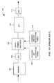
FIG 1A is a block diagram of aconventional transmitter 100 for a multicarrier modulation system. Thetransmitter 100 receives data signals to be transmitted at abuffer 102. The data signals are then supplied from thebuffer 102 to a forward error correction (FEC)unit 104. TheFEC unit 104 compensates for errors that are due to crosstalk noise, impulse noise, channel distortion, etc. The signals output by theFEC unit 104 are supplied to adata symbol encoder 106. Thedata symbol encoder 106 operates to encode the signals for a plurality of frequency tones associated with the multicarrier modulation. In assigning the data, or bits of the data, to each of the frequency tones, thedata symbol encoder 106 utilizes data stored in a transmit bit allocation table 108 and a transmit energy allocation table 110. The transmit bit allocation table 108 includes an integer value for each of the carriers (frequency tones) of the multicarrier modulation The integer value indicates the number of bits that are to be allocated to the particular frequency tone The value stored in the transmit energy allocation table 110 is used to effectively provide fractional number of bits of resolution via different allocation of energy levels to the frequency tones of the multicarrier modulation. In any case, after thedata symbol encoder 106 has encoded the data onto each of the frequency tones, an Inverse Fast Fourier Transform (IFFT)unit 112 modulates the frequency domain data supplied by thedata symbol encoder 106 and produces time domain signals to be transmitted. The time domain signals are then supplied to a digital-to-analog converter (DAC) 114 where the analog signals are converted to digital signals. Thereafter, the digital signals are transmitted over a channel to one or more remote receivers. -
FIG. 1B is a block diagram of aremote receiver 150 for a conventional multicarrier modulation system. Theremote receiver 150 receives analog signals that have been transmitted over a channel by a transmitter. The received analog signals are supplied to an analog-to-digital converter (ADC) 152. The ADC 152 converts the received analog signals to digital signals The digital signals are then supplied to a Fast Fourier Transform (FFT)unit 154 that demodulates the digital signals while converting the digital signals from a time domain to a frequency domain. The demodulated digital signals are then supplied to a frequency domain equalizer (FEQ)unit 156. TheFEQ unit 156 perfonns an equalization on the digital signals so the attenuation and phase are equalized over the various frequency tones. Then, adata symbol decoder 158 receives the equalized digital signals Thedata symbol decoder 158 operates to decode the equalized digital signals to recover the data, or bits of data, transmitted on each of the carriers (frequency tones). In decoding the equalized digital signals, thedata symbol decoder 158 needs access to the bit allocation information and the energy allocation information that were used to transmit the data. Hence, thedata symbol decoder 158 is coupled to a received bit allocation table 162 and a received energy allocation table 160 which respectively store the bit allocation information and the energy allocation information that were used to transmit the data. The data obtained from each of the frequency tones is then forwarded to the forward error correction (FEC)unit 164. TheFEC unit 164 performs error correction of the data to produce corrected data. The corrected data is then stored in abuffer 166. Thereafter, the data may be retrieved from thebuffer 166 and further processed by thereceiver 150. Alternatively, the received energy allocation table 160 could be supplied to and utilized by theFEQ unit 166. - One problem with the conventional design of transmitters and receivers of multicarrier modulation systems such as illustrated in
FIGs. 1 and2 is that only a single bit allocation is provided for transmission or reception of data symbols. In particular, thetransmitter 108 has a single set of bit allocation information stored in the transmit bit allocation table 108 and thereceiver 200 has a corresponding single set of bit allocation information stored in the receive bit allocation table 212. Although the bit allocation table is changeable, the processing time to update or change bit allocations is relatively slow and typically requires some sort of training process. With only a single bit allocation available to the multicarrier modulation system, the multicarrier modulation system is unable to rapidly alter its bit allocations for symbols being transmitted and received In other words, during transmission or reception of data, the bit allocations are fixed, and thus, all symbols being transmitted and received must use the same bit allocations. - Thus, there is a need for improved transmitters and receivers of multicarrier modulation systems that arc able to support multiple bit allocations so that multicarrier modulation systems are able to rapidly after their bit allocation
-
US Patent application 5495483 describes a communication system that utilizes DMT technology to couple a primary site (102) to a plurality of secondary sites (104-108), in which each path between a primary and secondary site communicates according to its site bit loading table. - Broadly speaking, the teachings herein disclose a method and apparatus for supporting multiple bit allocations in a multicarrier modulation system so that all symbols being transmitted or received can make use of different bit allocations. By supporting the multiple bit allocations, the multicarrier modulation system is able to support bit allocation on a superframe basis. The invention also pertains to selection and alignment of superframe formats to improve system performance The the teachings disclosed are also suitable for use in data transmission systems in which transmissions use a frame structure. The invention is also well suited for data transmission systems involving different transmission schemes where multiple bit allocations are helpful to reduce crosstalk interference.
- The invention can be implemented in numerous ways, as set forth in the appended set of claims.
- Other aspects and advantages of the invention will become apparent from the hollowing detailed description, taken in conjunction with the accompanying drawings, illustrating by way of example the principles of the invention.
- The present invention will be readily understood by the following detailed description in conjunction with the accompanying drawings, wherein like reference numerals designate like structural elements, and in which:
-
FIG 1A is a block diagram of a conventional transmitter for a multicarrier modulation system; -
FIG. 1B is a block diagram of a remote receiver for a conventional multicarrier modulation system; -
FIG. 2 is a block diagram of an exemplary telecommunications network suitable for implementing the invention; -
FIG. 3 is a block diagram of an exemplary processing and distribution unit according to an embodiment of the invention; -
FIG. 4A is a diagram illustrating an arrangement of superframe formats according to the invention; -
FIG. 4B illustrates a diagram of a mixed level of service provided by a multicarrier modulation system; -
FIG. 5 is a block diagram of a transmitter for a multicarrier modulation system according to an embodiment of the invention; -
FIG. 6 is a block diagram of a remote receiver for a multicarrier modulation system according to an embodiment of the invention; -
FIG. 7 is a block diagram of a transceiver according to an embodiment of the invention; -
FIG. 8 is a diagram of a superframe bit allocation table according to one embodiment of the invention; -
FIG 9 is a flow diagram of superframe bit allocation process according to one embodiment of the invention, -
FIG. 10A illustrates a flow diagram of a superframe bit allocation process according to another embodiment of the invention; -
FIG 10B illustrates a flow diagram of a superframe bit allocation process according to yet another embodiment of the invention; -
FIG. 11 is the flow diagram of superframe alignment processing according to an embodiment of the invention; -
FIG 12 is a flow diagram of optimized bit allocation processing, -
FIGs. 13A and 13B are diagrams of a superframe structure for ADSL and ISDN, respectively; and -
FIGs. 13C and 13D are diagrams of bit allocations for the superframe structure for ADSL transmissions such that NEXT interference from ISDN transmissions is reduced. - Embodiments of the invention are discussed below with reference to
FIGs. 2-13D . However, those skilled in the art will readily appreciate that the detailed description given herein with respect to these figures is for explanatory purposes as the invention extends beyond these limited embodiments. - The invention is useful for high speed data transmission where crosstalk interference can be a substantial impediment to proper reception of data. In particular, the invention is useful for VDSL and ADSL data transmissions using multicarrier modulation (e.g., DMT), wherein transmission frames for all lines are synchronized but the duration of the direction of transmissions can vary due to differing superframe formats The invention is also well suited for data transmission systems involving different transmission schemes such as ADSL and Integrated Service Digital Network (ISDN) where multiple bit allocations are helpful to reduce crosstalk interference (i.e , NEXT).
-
FIG. 2 is a block diagram of anexemplary telecommunications network 200 suitable for implementing the invention. Thetelecommunications network 200 includes acentral office 202. Thecentral office 202 services a plurality of distribution posts to provide data transmission to and from thecentral office 202 to various remote units In this exemplary embodiment, each of the distribution posts is a processing and distribution unit 204 (node). The processing anddistribution unit 204 is coupled to thecentral office 202 by a high speed, multiplexedtransmission line 206 that may take the form of a fiber optic line Typically, when thetransmission line 206 is a fiber optic line, the processing anddistribution unit 204 is referred to as an optical network unit (ONU). Thecentral office 202 also usually interacts with and couples to other processing, and distribution units (not shown) through high speed, multiplexedtransmission lines distribution unit 204 is discussed below In one embodiment, the processing anddistribution unit 204 includes a modem (central modem). - The processing and
distribution unit 204 services a multiplicity of discrete subscriber lines 212-1 through 212-n. Eachsubscriber line 212 typically services a single end user. The end user has a remote unit suitable for communicating with the processing anddistribution unit 204 at very high data rates More particularly, aremote unit 214 of afirst end user 216 is coupled to the processing anddistribution unit 204 by the subscriber line 212-1, and aremote unit 218 of asecond end user 220 is coupled to the processing, anddistribution unit 204 by the subscriber line 212-n. Theremote units distribution unit 204. In one embodiment, the data communication systems are modems. Theremote units FIG. 2 illustrates only a single remote unit coupled to a respective subscriber line, it should be recognized that a plurality of remote units can be coupled to a single subscriber line Moreover, althoughFIG. 2 illustrates the processing anddistribution unit 204 as being centralized processing, it should be recognized that the processing need not be centralized and could be performed independently for each of the subscriber lines 212. - The subscriber lines 212 serviced by the processing and
distribution unit 204 are bundled in a shieldedbinder 222 as thesubscriber lines 212 leave the processing anddistribution unit 204. The shielding provided by the shieldedbinder 222 generally serves as a good insulator against the emission (egress) and reception (ingress) of electromagnetic interference. However, the last segment of these subscriber lines, commonly referred to as a "drop" branches off from the shieldedbinder 222 and is coupled directly or indirectly to the end user's remote units The "drop" portion of the subscriber line between the respective remote unit and the shieldedbinder 222 is normally an unshielded, twisted-pair wire. In most applications the length of the drop is not more than about 30 meters. - Crosstalk interference, including near-end crosstalk (NEXT) and far-end crosstalk (FEXT) primarily occurs in the shielded
binder 222 where thesubscriber lines 212 are tightly bundled. Hence, when data is transmitted on some of thesubscriber lines 212 while other subscriber lines are receiving data as is common when multiple levels of service are being provided, the crosstalk inference induced becomes a substantial impairment to proper reception of data. Hence, to overcome this problem, data is transmitted using a superframe structure over which bits of data to be transmitted are allocated. Thetelecommunications network 200 is, for example, is particularly well suited for a SDMT transmission system offering different levels of service. One example of a SDMT transmission system is an SDMT VDSL system. - Hence, referring to the SDMT transmission system shown in
FIG. 2 , data transmissions over alllines 212 in the shieldedbinder 222 associated with the processing anddistribution unit 204 are synchronized with a master clock. As such, all active lines emanating from the processing anddistribution unit 204 could be transmitting in the same direction (i.e , downstream or upstream) so as to substantially eliminate NEXT interference. However, often all lines within the shieldedbinder 222 are not using SDMT or even when using SDMT include different levels of service. When different levels of service are used at a particular processing and distribution unit 204 (node), periods of transmission on some of the active lines will overlap with periods of reception on other active lines. Consequently, despite the use of SDMT, NEXT interference is undesirably present when different levels of service are used at a particular processing anddistribution unit 204. -
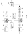
FIG. 3 is a block diagram of a processing anddistribution unit 300 according to an embodiment of the invention. For example, the data processing anddistribution unit 300 is a detailed implementation of the processing anddistribution unit 204 illustrated inFIG. 2 . - The data processing and
distribution unit 300 includes aprocessing unit 302 that receives data and sends data over adata link 304. The data link 304 could, for example, be coupled to a fiber optic cable of a telephone network or a cable network. Theprocessing unit 302 also receives amaster clock 306 for providing synchronization to various processed transmissions and receptions of theprocessing unit 302. The data processing anddistribution unit 300 further includes abus arrangement 308 and a plurality ofanalog cards 310. The output of theprocessing unit 302 is coupled to thebus arrangement 308. Thebus arrangement 308 together with theprocessing unit 302 thus direct output data from theprocessing unit 302 to theappropriate analog cards 310 as well as direct input from theanalog cards 310 to theprocessing unit 302. Theanalog cards 310 provide analog circuitry utilized by the processing anddistribution unit 300 that is typically more efficiently perform with analog components than using digital processing by theprocessing unit 302. For example, the analog circuitry can include filters, transformers, analog-to-digital converters or digital-to-analog converters. Each of theanalog cards 310 are coupled to a different line. Typically, all the lines for a givendata transmission system 300 are bundled into a binder including about fifty (50) lines (LINE-1 through LINE-50) Hence, in such an embodiment, there are fifty (50)analog cards 310 respectively coupled to the fifty (50) lines. In one embodiment, the lines are twisted-pair wires. The processing,unit 302 may be a general-purpose computing device such as a digital signal processor (DSP) or a dedicated special purpose device. Thebus arrangement 308 may take many arrangements and forms. Theanalog cards 310 need not be designed for individual lines, but could instead be a single card or circuitry that supports multiple lines. - In a case where the processing is not centralized , the
processing unit 302 inFIG. 3 can be replaced by modems for each of the lines The processing for each of the lines can then be performed independently for each of the lines. In this case, the modem may be placed on a single card along with the analog circuitry - The NEXT interference problem occurs on the lines proximate to the output of the processing and
distribution unit 300 With respect to the block diagram illustrated inFIG. 3 , the NEXT interference is most prevalent near the outputs of theanalog cards 310 because this is where the lines are closest to one another and have their largest power differential (between transmitted and received signals) In other words, from the output of the processing anddistribution unit 300 the lines travel towards the remote units. Usually, most of the distance is within a shielded binder that would, for example, hold fifty (50) twisted-pair wires, and the remaining distance is over single unshielded twisted-pair wires. Because all these lines (e.g., twisted-pair wires) are held in close proximity in the binder and individually offer little shielding against electromagnetic coupling from other of the lines in the binder, crosstalk interference (namely NEXT interference and FEXT interference) between the lines within the binder is problematic. The invention provides useful techniques to reduce the effects of the undesired crosstalk interference. - Depending on the level of service being provided, data transmission implemented with SDMT can be symmetric or asymmetric with respect to upstream and downstream transmissions With symmetric transmission, DMT symbols tend to be transmitted in alternating directions for equal duration. In other words, the duration in which DMT symbols are transmitted downstream is the same as the duration in which DMT symbols are transmitted upstream. With asymmetric transmission, DMT symbols tend to be transmitted downstream for a longer duration than upstream.
- In VDSL it has been proposed to have a frame superframe structure a fixed number (e.g., 20) frames, with each frame being associated with a DMT symbol. With such a frame superframe, the number of frames being used for downstream transmissions and the number of frames being used for upstream transmissions can vary. As a result, there are several different superframe formats that can occur. Between the upstream and the downstream frames quiet frames are inserted to allow the channel to settle before the direction of transmission is changed
-
FIG. 4A is a diagram illustrating anarrangement 400 of superframe formats according to the invention. Thearrangement 400 illustrates nine (9) different superframe formats, each of which use a twenty (20) frame format. Each of the superframe formats has one or more downstream frames ("D" or "Down"), one or more upstream frames ("U" or "Up"), and a quiet frame ("Q") between the transitions in direction of transmission. InFIG. 4A , each of the superframe formats is described by a descriptive set of numbers. For example, the first superframe format in thearrangement 400 is denoted "17-1-1-1" to indicate that there are 17 downstream frames, 1 quiet frame, 1 upstream frame, and 1 quiet frame. As another example, the last superframe format in thearrangement 400 is denoted "9-1-9-1" to indicate that there are 9 downstream frames, 1 quiet frame, 9 upstream frames, and 1 quiet frame, and is referred to as a symmetric format because the same amount of francs are allocated to upstream and downstream transmissions. - In synchronized DMT (SDMT) if all the lines within a binder at an optical network unit (ONU) must use the same superframe format, then the near-end crosstalk (also known as NEXT interference) is effectively diminished because all of the lines within a binder at the ONU are transmitting at the same time and likewise receiving at the same time. The disadvantage of this transmission scheme is that the mixture of service provided to each of the lines is all the same. Hence, it is very likely that some remote users will be receive too much upstream bandwidth and too little downstream bandwidth and other remote users will be receive too much downstream bandwidth and too little upstream bandwidth. Also, when the lines at a binder of the ONU are not all synchronized to the same superframe format, the NEXT interference becomes a concern.
- One technique to compensate for the NEXT interference is to provide crosstalk cancellers as is described in
U.S. Patent No. 5,887,032 . The use of crosstalk cancellers in this manner operates to compensate for NEXT interference, but does not pertain to superframe format selection, alignment or bit allocation. The crosstalk cancellers also have a significant amount of complexity and tend to be most suitable when there are only a few dominant crosstalkers. - Another technique to compensate for the NEXT interference is provided by the invention. According to the invention, mixed levels of service are able to be provided by allowing lines within a binder to choose the most suitable superframe format in accordance with the level of service desired and the noise or interference present. Furthermore, according to the invention, the impact of NEXT interference (due to mixed levels of service being provided) to lines in the same binder is taken into consideration when aligning one superframe format with one or more other superframe formats and/or when allocating bits to the symbols. Hence, according to the invention, the impact of NEXT interference is significantly reduced.
- In the
arrangement 400 illustrated inFIG. 4A , the multiple superframe formats are aligned with one another so as to minimize or at least reduce the negative impact of interference, namely NEXT interference In particular, thearrangement 400 provides one preferred, predetermined way to align the superframe. However, if less the nine (9) superframe formats are offered to subscribers, or if less of the formats are in use, then more options of other alignments become possible with similar benefits being obtain with respect to the minimization of the impact of NEXT interference. In general, the object is to have the synchronized frames for downstream traffic overlap one another in the various superframe formats, and then to the extent possible minimize the number of frames for upstream traffic of a given superframe format that overlap with frames for downstream traffic of any of the other superframe formats. -
FIG. 4B illustrates a diagram of a mixed level ofservice 450 provided by a multicarrier modulation system. In this example, it is assumed that at an ONU (e.g., processing and distribution unit 204) there are two lines in service. It is also assumed that a first line in service is using afirst superframe format 452, and a second line in service is using asecond superframe format 454. Thefirst superframe format 452 corresponds to the "16-1-2-1" superframe format inFIG. 4A , and thesecond superframe format 454 corresponds to the "9-1-9-1" superframe format inFIG. 4A . - In
FIG. 4B , the first and second superframe formats 452 and 454 are illustrated as being aligned in a particular way so as to minimize NEXT interference between the two lines providing different levels of service. For transmissions going in the same direction between the two lines, far-end crosstalk (FEXT interference) is present. For transmissions going in the opposite direction between the two lines, NEXT interference is present. Usually, the NEXT interference is substantially more severe than the FEXT interference, and thus it is advantageous to minimize the NEXT interference even if additional FEXT interference results. Also note that the NEXT interference is much worse at the ONU side than the remote receiver side where receivers tend to be physically different positions. - For example, in the alignment of the first and second supertrame formats 452 and 454 in
FIG. 4B , the frames A, B, C. H and J of thesecond superframe format 454 which carry upstream transmissions are negatively impacted by NEXT interference from the downstream transmissions according to thefirst superframe format 452 by the ONU. Hence, with the alignment of the first and second superframe formats 452 and 454 illustrated inFIG. 4B , only five (5) of the nine total frames transmitting in the upstream direction suffer from NEXT interference On the other hand, the worse case alignment of the first and second superframe formats 452 and 454 would be that all nine (9) of the upstream frames of thesecond superframe format 454 would be susceptible to NEXT interference from the downstream transmissions of thefirst superframe format 452. Also, if the channel response is reasonably short, then upstream frames D and G would have no NEXT interference and no FEXT interference. The upstream frames E and F of thesecond superframe format 454 would have FEXT interference from thefirst superframe format 452. - Given that whenever a mixture of levels of service are provided, different frames within the superframe format assigned to a line will be subjected to substantially different interference from corresponding frame of other lines in the binder at the ONU side. Accordingly, for each of the lines, the interference across the superframe format may be significantly different at different frames. More particularly, different frequency tones of the frames may be subjected to different levels of interference across the superframe format. As a result, the conventional approach illustrated in
FIGs. 1A and1B of having only a single bit allocation table for transmissions in a given direction is a significant limitation to the performance of the multicarrier modulation system and its ability to support superframes. For example, with respect to the upstream transmissions on the line utilizing thesecond superframe format 454 illustrated inFIG. 4B , several different bit allocations (for the superframe) would be useful to optimizing the upstream transmission performance. For example, it would be advantageous to be able to carry less information (e g., bits of data) on the nine (9) frames carrying upstream transmissions (namely, frames A, B, C, H, and J) that suffer from large amounts of NEXT interference, and to carry more information on those frames that suffer from little or no NEXT interference. Further, it would also be an advantage to carry more data on those frames that suffer from little or no NEXT or FEXT interference, and less data on the frames that suffer from FEXT interference but little or no NEXT interference. -
FIG. 5 is a block diagram of atransmitter 500 for a multicarrier modulation system according to an embodiment of the invention. Thetransmitter 500 is able to support multiple different bit allocations within a superframe as well as different superframe formats. - The
transmitter 500 receives at thebuffer 102 data signals to be transmitted. The data signal are then supplied to theFEC unit 104. TheFEC unit 104 performs error correction on the data signals, and then supplies the data signals to adata symbol encoder 502. Thedata symbol encoder 502 encodes the data signals onto a plurality of frequency tones associated with a symbol (frame). In allocating the bits to the particular frequency tones of the symbol, thedata symbol encoder 502 obtains bit and energy allocation information from a superframe bit allocation table 504 and a superframe energy allocation table 506, respectively. - The
transmitter 500 is capable of supporting a multitude of superframe formats, and as such, thedata symbol encoder 502 must be able to retrieve a variety of different bit allocations for the various frames of the superframe. In other words, the superframe bit allocation table 504 includes, in effect, a bit allocation table for each downstream transmission frame in the superframe format. For example, with respect to the example illustrated inFIG. 4A , the maximum number of frames in the downstream direction is seventeen (17); hence, the superframe bit allocation table 504 would include seventeen different individual bit allocation tables As illustrated inFIG. 5 , these bit allocation tables for each of the frames transmitting in the downstream direction are identified as FR-1, FR-2, FR-3, .., FR-n in the superframe bit allocation table 504 Likewise, the superframe energy allocation table 506 may include individual energy allocation tables for each of the frames transmitting in the downstream transmission direction are identified inFIG 5 as FR-1, FR-2, For-3, ..., FR-n. As a result, each frame for downstream transmissions in the superframe can optimize its bit allocations over the superframe. - After the symbols have been created, they are supplied to the
IFFT unit 112 for modulation and conversion to the time domain. Typically, although not shown, a cyclic prefix is added to the time domain signals. The resulting time domain signals are converted to analog signals by theDAC unit 114. Thetransmitter 500 also includes acontroller 508 that operates to control, among other things, the proper selection of the effectively individualized allocation tables from the superframe bit allocation table 504 and the proper selection of the effectively individualized energy allocation tables from the superframe energy allocation table 506. In this way, thedata symbol encoder 502 utilizes better bit allocations for the particular frames of a superframe format. Thecontroller 508 may also control thetransmitter 500 to transmit data in accordance with a superframe format. - Although the superframe bit allocation table 504 may be arranged so as to provide individual bit allocation tables for each frame of the superframe, the
superframe bit allocation 504 can be one large table having different portions containing bit allocation information for different frames of the superframe. Further, the superframe bit allocation table 504 need not have separate bit allocation information, or bit allocation tables, for each of the frames of the superframe; instead, thesuperframe bit allocation 504 could include bit allocation information, or bit allocation tables, for a group of frames. The superframe energy allocation table 506 is optionally provided in thetransmitter 500 to allow for fractional bits to be encoded on a symbol by thedata symbol encoder 502, but if provided, typically has an arrangement similar to that of the superframe bit allocation table 504. -
FIG. 6 is a block diagram of aremote receiver 600 for a multicarrier modulation system according to an embodiment of the invention. Like thetransmitter 500, theremote receiver 600 is able to support (i) multiple different bit allocations within a superframe and (ii) different superframe formats. - The
remote receiver 600 receives analog signals from a channel and supplies them to theADC unit 152. Typically, although not shown, the cyclic prefix (if transmitted) would be removed and time domain equalization of the digital signals from theADC unit 152 would be performed. The resulting digital signals are then supplied to theFFT unit 154. TheFFT unit 154 produces frequency domain data by demodulating the incoming data signals and converting the signals from the time domain to the frequency domain. The frequency domain data is then equalized by theFEQ unit 156. The equalized frequency domain data is then supplied to adata symbol decoder 602. Thedata symbol decoder 602 operates to receive the equalized frequency domain data and decode the data from each of the frequency tones associated with the frame being received. In decoding the symbols, thedata symbol decoder 602 utilizes energy allocation information from a superframe energy allocation table 604 and bit allocation information from a superframe bit allocation table 606. The energy and bit allocation information stored in the superframe tables 604 and 606 is such that a variety of effectively different bit and energy allocation tables can be used to decode frames in a superframe. The decoding is, however, dependent on the particular allocation used to encode respective frames in the superframe at the transmitter. Alternatively, the supertrame energy allocation table 604 can be supplied to and utilized by theFEQ unit 156. In any case, the decoded data is then supplied to theFEC unit 164 which provides forward error correction. The decoded data is then stored in thebuffer 166 for subsequent use by thereceiver 600 Thereceiver 600 also includes acontroller 608 that operates to control the selection of the appropriate bit allocation information and the appropriate energy allocation information for use with respect to particular frames within the superframe format. Thecontroller 608 may also control thereceiver 600 to receive incoming analog signals in accordance with the particular superframe format that was used by the associated transmitter. -
FIG. 7 is a block diagram of atransceiver 700 according to an embodiment of the invention Thetransceiver 700 has both a transmitter side and a receiver side and is suitable for bi-directional data transmission. The transmitter side transmits data by supplying it to thebuffer 102. The data is then obtained from thebuffer 102 and supplied to theFEC unit 104. Adata symbol encoder 702 then operates to encode the data on to frequency tones of a symbol based on bit allocation information obtained from a superframe transmit bit allocation table 704. The encoded data is then supplied to theIFFT unit 112 which modulates the data and converts the modulated data into time domain data. The time domain data is then converted to analog signals by theDAC 114. The analog signals are then supplied to ahybrid circuit 706 and transmitted over a channel. - The receiver side of the
transceiver 700 receives analog signals that have been transmitted over a channel via thehybrid circuit 706. The received analog signals are then supplied to theADC 202 which converts the received digital signals to digital signals. The digital signals are then supplied to theFFT unit 204 which produces frequency domain signals. The frequency domain signals are then equalized by theFEQ unit 206. The equalized signals are then supplied to adata symbol decoder 708. Thedata symbol decoder 708 operates to decode the equalized signals to recover data that has been transmitted on each of the frequency tones of the symbol being received. The decoding by thedata symbol decoder 708 is performed based on bit allocation information stored in a superframe receive bit allocation table 710. The decoded data is then supplied to theFEC unit 214 and then stored in thebuffer 216. - Generally speaking, the bit allocation information stored in the superframe transmit bit allocation table 704 and the bit allocation information stored in the superframe receive bit allocation table 710 are not the same due to different noise impairments. The superframe transmit bit allocation table 704 would, for example, contain bit allocation information that is to be utilized in coding data to be transmitted in the various downstream frames of a superframe format. On the other hand, the received bit allocation information stored in the superframe receive bit allocation table 710 could, for example, contain bit allocation information to be utilized in decoding the frames of the superframe format that are received from a remote receiver transmitting in the upstream direction.
-
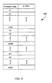
FIG. 8 is a diagram of a superframe bit allocation table 800 according to one embodiment of the invention. The superframe bit allocation table 800 in this embodiment is a single table including bit allocation information for each of the frequency tones of each of the frames for a given direction. For example, if the superframe bit allocation table 800 is for a transmitter, then the bit allocation would be provided for those of the frames that could possibly transmit in the downstream direction. In the case of a data transmission system offering the superframe formats shown inFIG. 4A , the superframe bit allocation table 800 could contain bit allocation information for up to seventeen (17) frames. However, it should be recognized that the size of the superframe bit allocation table could also be made smaller by requiring various of the frames which experience similar channel conditions to share or utilize the same bit allocation information. - The above-described exemplary apparatuses for the invention permit a number of new processing operations that are able to enhance the operation of data transmission systems such as multicarrier modulation systems. These new processing operations form other aspects of the invention and are explained in detail below.
-
FIG. 9 is a flow diagram of superframebit allocation process 900. Initially, the number of bits required to support a requested level of service in a given direction is determined 902. Then, performance information for symbols in the superframe is obtained 904. As an example, the performance information may be signal-to-noise ratio (SNR) information. Next, the determined number of bits required to support the requested level of service are allocated 906 to symbols in the superframe based on the performance information. The resulting allocations are then stored 908. Followingblock 908, the superframebit allocation processing 900 is complete and ends. - In general, the superframe
bit allocation process 900 allocates the bits of data to be transmitted over a superframe. By allocating over a superframe, the superframebit allocation process 900 is able to take differing amounts of interference present on lines (e.g., NEXT interference) within a superframe into consideration. In other words, the interference on lines from frame to frame will vary within the superframe, and theallocation process 900 takes such variations into account in allocating bits. Consequently, those of the subchannels of a given superframe being subjected to large amounts of NEXT interference will receive less bits to transmits, and other subchannels being subjected to small amounts of NEXT interference will receive more bits to transmit. The transmission and reception of data is therefore better optimized by the invention.FIG. 10A illustrates a flow diagram of a superframebit allocation process 1000. In this embodiment, a request for services is given in connection with achieving a maximum acceptable data rate. - The superframe
bit allocation processing 1000 initially identifies 1002 an acceptable performance margin for requested service. The performance margin for the data transmission is typically requested by a requester. An example of an acceptable performance margins is: bit error rate of 10-7 with a 6 dB noise margin. Requested number of bits required to support requested service(s) are identified 1004. Typically, there is more than one acceptable requested service. For example, a network may be requesting service at 26 Mbit/s but if unavailable will accept service at 13 Mbit/s. Signal-to-noise ratio (SNR) information is also obtained 1006 for symbols is the superframe. The SNR information can be obtained by estimating channel response and measuring noise variance on a line. - Next, a number of bits that each tone of each of the symbols in the superframe is able to support is determined 1008 based on the acceptable performance margin and the SNR information. Then, a total number of bits that each of the symbols can support is determined 1010. The total number of bits that each symbol can support can be determined by adding the number of bits each tone within the symbol can support.
- Then, the total numbers for the symbols obtained in
block 1008 are added 1010 to obtain an aggregate total number of bits. To the extent necessary, the aggregate total number of bits is truncated 1014 to an available network data rate, namely to a data rate of one of the requested services. For example, if the aggregate total number of bits indicates a maximum data rate of 20 Mbit/s, then the number of bits to be allocated would be truncated to 13 Mbit/s where the requested services are 26 Mbit/s and 13 Mbit/s. - The determined number (i.e., the truncated number) of bits are then allocated 1014 to the symbols in the superframe. The allocation of the bits to the various frames and tones in the superframe can use various techniques, including those known techniques used to allocate bits in single frames. Eventually, the bits are allocated to the individual frequency tones of the symbols. Thereafter, the allocations for each symbol are stored 1018. As an example, the bit allocations for the superframe can be stored in the superframe bit allocation table. Following
block 1016, the superframebit allocation processing 1000 is complete and ends. -
FIG. 10B illustrates a flow diagram of a superframebit allocation process 1050. A request for service is given in connection with at least a certain performance margin. - The superframe
bit allocation processing 1050 initially performs the same operations as blocks 1002 - 1012 of thebit allocation processing 1000 ofFIG. 10A . Followingblock 1012, adecision block 1052 determines whether the aggregate total number of bits matches the requested number of bits. - When the aggregate total number of bits does not match the requested number of bits, the performance margin is adjusted 1054. The amount of adjustment can be made dependent on the separation of the aggregate total number of bits and the requested number of bits. Next, a
decision block 1056 determines if the performance margin is still acceptable. Here, the performance margin existing after theadjustment 1054 is compared to the acceptable performance margin prevously identified 1002. When the performance margin is determined not be acceptable after theadjustment 1054, then the requested service falls back 1058 to the next acceptable data rate. Followingblock 1058 as well as following thedecision block 1056 when the performance margin is determined to be acceptable after theadjustment 1054, thebit allocation processing 1050 returns to repeatblocks 1008 and subsequent blocks in an iterative fashion. - When the aggregate total number of bits does (eventually) match the requested number of bits, the requested number of bits are allocated 1060 to the symbols. Again, the allocation of the bits to the various frames and tones in the superframe can use various techniques, including those known techniques used to allocate bits in single frames. Thereafter, the allocations for each symbol are stored 1062, As an example, the bit allocations for the superframe can be stored in the superframe bit allocation table. Following
block 1062, the superframebit allocation processing 1050 is complete and ends. The superframebit allocation processing 1050 could also end if thedecision block 1052 is unable to find a match after a predetermined number of iterations. - It should be noted that the allocation of bits to the symbols achieved by
block 1062 can be stored in the superframe bit allocation table in many ways. With a full size superframe bit allocation table, each symbol can be effectively provided with its own bit allocation table that specifies the number of bits placed on each of the frequency tones. However, with a less than full size superframe bit allocation table, groups of symbols share effective bit allocation tables. The symbols can be grouped in a number of ways. One way to group the symbols is to consider those symbols having similar SNR information. Another way to group the symbols is to consider those symbols which are determined to be able to support a nearly equal number of bits. - Applying the superframe
bit allocation processes second superframe format 454 in thearrangement 450 illustrated inFIG. 4B , might operate to perform bit allocations as follows when symbols or frames are grouped. First, symbols A, B, C, H and J could be grouped together and labeled as group X symbols, symbols D and G could be grouped and labeled as group Y symbols, and E and F could be grouped and labeled group Z symbols. Then, starting with a performance margin of, say, 6 dB, bit allocations are separately or jointly determined for the symbol groups X, Y and Z, and the resulting total bits supported by symbols X. Y, Z are BX, BY, and BZ respectively. The total number of bits that this system supports with the given performance margin is then equal to 5BX + 2BY + 2BZ = B1. Next, assume that B is the total number of bits required to support a given payload or service requested. The ratio of B1/B and the ratio of 5BX vs. 2BY vs. 2BZ are used to determine how the bits need to be allocated. This ratio is then able to be used to adjust the performance margin 1054 (FIG. 10A ) or truncate 1014 and/or allocate 1016 the bits (FIG. 10B ). Several iterations may be necessary to achieve accurate and near optimal results. - When a mixture of levels of service are provided by an ONU side, the levels of service being simultaneously provided will often change as new service starts on some lines and existing service stops on other lines. As a result, the particular superframes that are concurrently active is not constant. Also, the interference between these mixed levels of service provided by the different superframe formats is likewise not constant. Hence, it is advantageous to provide techniques for selecting an appropriate superframe format of a line requesting a level of service and then aligning the selected superframe format with the existing superframe formats already in service. Such techniques thus operate to improve the efficiency of data transmission by minimizing the impact of interference between the various lines in service.
-
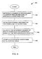
FIG. 11 is the flow diagram ofsuperframe alignment processing 1100. Thesuperframe alignment processing 1100 initially receives 1102 a service request. Then, SNR information is obtained 1104 for all slots in a superframe. Preferably, the slots refer to frequency tones within the superframe. Then, a superframe format is selected 1106 for the service request. Typically, the service request would indicate a transmission rate with some required quality of service for both downstream and upstream levels of service. As an example, the service request for a particular direction might be a bit error rate of less than 10-7 with 6 dB noise margin. An appropriate superframe format can be selected using the information from the service request. For example, if the downstream data rate requested is twice the upstream data rate requested, then the superframe format would likely require twice as many downstream frames as upstream frames. For this example, the superframe format "12-1-6-1" illustrated inFIG. 3 might be appropriate. - Next, an alignment for the selected superframe is selected 1108 At this point, the alignment is not necessarily the final alignment but is one alignment that is possible for the selected superframe. Then, bits are allocated 1110 to slots of the selected superframe for downstream transmissions with the selected alignment. In general, the bit allocation can be performed based on either a performance measure or a data rate. With the performance measure approach, a maximum total data rate is computed and then a suitable data rate for the requested service is determined. With the data rate approach, a performance margin for the superframe is determined and then compared with the performance margin of the requested service
- A performance measure for the selected superframe with the given allocation is then determined 1112 Next, a
decision block 1114 determines whether the performance measure is greater than a predetermined threshold. If the performance measure does not exceed the predetermined threshold, then it is assumed that the alignment of the selected superframe is not the most desirable alignment. In this case, adecision block 1116 determines whether or not there are additional alignments of the selected superframe to be considered. If there are additional alignments to be considered, thesuperframe alignment processing 1110 returns to repeat blocks 1108 and subsequent blocks for a different alignment of the selected superframe. - On the other hand, when there are no more additional alignments to be considered, the best available alignment is chosen 1118 in accordance with their respective performance measures. In other words, of all the alignments considered for the selected superframe, the alignment providing the best performance measure is chosen Following
block 1118. thesuperframe alignment processing 1100 is completed. Also, when thedecision block 1114 determines that the performance measure of a given alignment does exceed a predetermined threshold, then thesuperframe alignment processing 1100 may operate to end early without considering other alignments. The predetermined threshold could, for example, be a performance margin threshold or a data rate threshold. Thedecision block 1114 is optional and it may be preferred to endure the potentially extra processing time and consider all possible alignments before choosing an alignment for the superframe. - The
superframe alignment processing 1100 could also consider fractional alignments in which the frame boundaries in one superframe are offset from frame boundaries of frames in another superframe. In this case, the block 1104 should be positioned betweenblocks 1108 and 1110 so that the SNR information can be reacquired for the fractional alignment. -
FIG. 12 is a flow diagram of optimizedbit allocation processing 1200. The optimizedbit allocation processing 1200 initially receives 1202 a service request. A suitable superframe format is then estimated 1 204 based on the service request. Next, a best alignment is determined 1206 for the estimated superframe format. As an example, the best alignment can be determined 1206 using thesuperframe alignment processing 1100 illustrated inFIG. 11 . After the best alignment is determined 1206, bits are allocated 1208 to slots of the estimated superframe format. Then, a performance measure is determined 1210 for the estimated superframe. The performance measure for the estimated superframe provides a performance indication for the best alignment of the estimated superframe. - Next, a
decision block 1212 determines whether there are additional superframe formats that would be suitable for consideration. If there are additional formats that are suitable for consideration, another suitable superframe format is selected 1214 and then processing returns to repeatblock 1206 and subsequent blocks. - On the other hand, when the
decision block 1212 determines that there are no more additional suitable superframe formats to be considered, the superframe format offering the best performance is then chosen 1216. In other words, using the performance measures for each of the estimated superframes, the particular superframe format offering the best performance is selected. Then, bits are allocated 1218 to slots of the chosen superframe format with its best alignment which was previously determined. Then, the allocations are stored 1220 in a superframe bit allocation table. If the storage capacity of the superframe bit allocation table is limited, then the optimizedbit allocation processing 1200 may operate to group certain symbols having similar performance or interference characteristics, and then to allocate bits to the symbols and then to frequency tones of the symbols. Followingblock 1220 the optimizedbit allocation processing 1200 is complete and ends - A variety of allocation techniques can be adapted for allocation over a superframe according to the invention. As examples, the allocation techniques described in the following documents may be adapted by those skilled in the art: (1)
U.S. Patent 5,400,322 ; (2) Peter S. Chow et al.. A Practical MultiTone Transceiver Loading Algorithm for Data Transmission over Spectrally Shaped Channels, IEEE Transactions on Communications, Vol. 23. No. 2/3/4. February, March/April 1995; and (3) Robert F.H. Fischer at al., A New Loading Algorithm for Discrete Multitone Transmission, IEEE 1996. - Furthermore, the bit allocations once initially established can be updated using a number of techniques. One suitable technique uses bit swapping within a superframe. Bit swapping within a frame is described in
U.S. Patent 5.400,322 . With a superframe structure the bit swapping now can be swapped for bits anywhere within the superframe. Such updating serves to keep the bit allocation for the superframe constant but flexible enough to compensate for noise variances that vary from superframe to superframe. - Although much of the discussion concerns superframe bit allocations for VDSL transmissions, the invention is also applicable to other superframe transmission schemes such as ADSL. Unlike the time domain division (TDD) transmissions in VDSL, ADSL uses frequency domain division (FDD) or echo cancellation to separate upstream transmissions from downstream transmissions. Conventionally, with ADSL, the superframe has a plurality of frames that form a superframe. Each frame is referred to as a symbol For a given transmission direction, the bit allocations for each of the symbols within the superframe are conventionally the same across the superframe for a given transmission direction. However, according to another aspect of the invention, multiple bit allocations for a given transmission direction are provided so that the impact of undesired crosstalk interference can by reduced.
- In the case where transmission schemes are mixed, there can be crosstalk interference (i.e., NEXT) between the transmission schemes. The crosstalk interference) can be particularly severe when the transmission schemes are mixed with a common binder. In one embodiment, ADSL and ISDN transmission schemes are mixed. Here, ISDN is a time domain division (TDD) and ADSL is either frequency domain division (FDD) or echo canceled. In other words, ADSL transmissions are concurrently occurring in both upstream and downstream directions while, at the same time, ISDN periodically alternates between downstream and upstream transmissions.
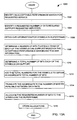
- Initially, with the mixed ADSL and ISDN transmission schemes, ADSL transmissions in accordance with its superframe are synchronized with the superframe of ISDN.
FIGs 13A and 13B are diagrams ofsuperframe structures ADSL superframe 1302 is synchronized to theISDN superframe 1300. - With the synchronization of superframes, crosstalk interference on the ADSL transmissions induced by the ISDN transmissions are particularly problematic when the ADSL transmissions are transmitted in the direction opposite that of the ISDN transmissions. For example, the
ADSL superframe 1302 includes four portions, namely, a firstdownstream portion 1304, a firstupstream portion 1306, a seconddownstream portion 1308, and a secondupstream portion 1310. The firstupstream portion 1306 of theADSL superframe 1302 is subjected to large amounts of crosstalk interference (e.g., NEXT interference) do to the concurrently occurring downstream ISDN transmissions. When the mixed transmission schemes are combined with the same binder, the crosstalk interference can be particularly severe. - Conventionally, the bit allocations assigned to the various tones with each of the symbols in an ADSL superframe are the same for all frames of a superframe, though the bit allocations could differ between upstream and downstream transmissions. As such, transmission systems for ADSL conventionally supported only a single bit allocation for each transmission direction. The bit allocations are also conventionally determined by averaging the signal-to-noise ratio (SNR) over time and then allocating bits to each of the tones based on the SNR values.
- However, in the case of mixed transmission schemes, such as ISDN and ADSL, the crosstalk is not uniformly provided over the superframe. Accordingly, the invention uses multiple bit allocations for each transmission direction so that improved bit allocations are attained. The improved bit allocations takes into consideration the crosstalk interference from the periodic ISDN transmissions so as to provide more robust and efficient ADSL data transmissions.
- In one embodiment, the multiple bit allocations for each transmission direction are provided by different bit allocation tables. For example, in one embodiment, each of the first
downstream portion 1304, the firstupstream portion 1306, the seconddownstream portion 1308 and the secondupstream portion 1310 have a separate bit allocation table -
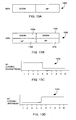
FIGs. 13C and 13D are diagrams of bit allocations for the ADSL superframe These diagrams 1312 and 1314 assume a superframe structure of ten (10) symbols. - In
FIG. 13C , the bit loading is for downstream ADSL transmissions and the bit loading is relatively greater in symbols 1-5 as opposed to symbols 6-10. Here, the symbols 1-5 would use a first downstream bit allocation table and the symbols 6-10 would use a second downstream bit allocation table. The first and second downstream bit allocations can be implemented in a superframe bit allocation table Hence, the bit allocations are noticeable reduced (i.e., less data transmitted per symbol) during the seconddownstream portion 1308 because of the crosstalk interference from ISDN transmissions during the seconddownstream portion 1308 but not during the firstdownstream portion 1304 - In
FIG. 13D , the bit loading is for upstream ADSL transmissions and the bit loading is relatively lower in symbols 1-5 as opposed to symbols 6-10. Here, the symbols 1-5 would use a first upstream bit allocation table and the symbols 6-10 would use a second upstream bit allocation table The first and second upstream bit allocations can be implemented in a superframe bit allocation table Hence, the bit allocations are noticeable reduced (i.e., less data transmitted per symbol) during the firstupstream portion 1306 because of the crosstalk interference from ISDN transmissions during the firstupstream portion 1306 but not during the secondupstream portion 1310. - In the case of mixed transmission schemes (e.g., ISDN and ADSL), by using these multiple bit allocations for each transmission directions, crosstalk interference can be reduced. By reducing crosstalk interference in this manner, the invention enables faster and more reliable data transmission to be achieved.
- The many features and advantages of the present invention are apparent from the written description, and thus, it is intended by the appended claims to cover all such features and advantages of the Invention. Further, since numerous modifications and changes will readily occur to those skilled in the art, it is not desired to limit the invention to the exact construction and operation as illustrated and described. Hence, all suitable modifications and equivalent may be resorted to as falling within the scope of the invention, as defined by the appended claims.
Claims (24)
- A transmitter (500) for a data transmission system using multicarrier modulation on a superframe basis, the superframe comprising a plurality of frames, said transmitter comprising:first and second bit allocation tables (504,800), storing first and second bit allocation information, respectively;a data symbol encoder (502) for encoding bits, associated with digital data to be transmitted, to frequency tones of each of the plurality of frames using a selected one of the first and second bit allocation information;a multicarrier modulation unit (112), said multicarrier modulation unit modulates the encoded bits on the frequency tones to produce modulated signals; anda digital-to-analog converter(114), said digital-to-analog converter converts the modulated signals to analog signals;characterized by:the data symbol encoder encoding at least one frame within the plurality of frames (452,454) for transmissions to a receiver using the first bit allocation information and encoding at least one other frame within the plurality of frames (452,454) for that receiver using the second bit allocation information.
- The transmitter of claim 1, wherein said first and second bit allocation tables are individual bit allocation tables.
- The transmitter of claim 1, wherein said first and second bit allocation tables are arranged as first and second portions of a larger bit allocation table (800).
- The transmitter of any one of claims 1 to 3, further comprising:a buffer (102), having an input for receiving the digital data to be transmitted, and having an output coupled to the data symbol encoder (502); anda controller (508) operatively connected to the first and second bit allocation tables, for controlling retrieval of the selected one of the first and second bit allocation information.
- A transmitter as recited in claim 1, wherein said modulation unit modulates the encoded bits on the frequency tones of a symbol using Discrete Multi Tone, DMT, modulation.
- A transmitter as recited in claim 1, further characterized by bit allocations in the first bit allocation table being greater than those in the second bit allocation table to reduce impact of crosstalk interference from other transmission schemes.
- The transmitter of claim 6, wherein said transmitter transmits data through a binder of transmission wires (212-1), and
wherein the other transmission schemes also transmit and receive data through the binder. - The transmitting apparatus of claim 6 or claim 7, wherein one of the other transmission schemes has a first time period associated with communication of data away from the transmitter and a second time period associated with communication of data toward the transmitter;
wherein transmission of the multiple frames (1304) of the plurality of frames encoded using the first bit allocation information occurs during the first time period. - The transmitting apparatus of claim 8, wherein transmission of the multiple frames (1308) of the plurality of frames encoded using the second bit allocation information occurs during the second time period.
- An apparatus (600) for recovering data transmitted by a transmitter for a data transmission system using multicarrier modulation on a superframe basis, the superframe comprising a plurality of frames, said apparatus comprising:an analog-to-digital converter (152), said analog-to-digital converter arranged to receive transmitted analog signals and produce digital signals therefrom, the transmitted analog signals being time domain signals representing data transmitted;a demodulator (154), said demodulator arranged to receive the digital signals and demodulate the digital signals to produce digital frequency domain data;first and second bit allocation tables (606,800) storing first and second bit allocation information, respectively; anda data symbol decoder (602) for decoding bits associated with the digital frequency domain data from frequency tones of each of the plurality of frames using a selected one of the first and second bit allocation information;characterized by:the data symbol decoder decoding at least one frame of the plurality of frames (452,454) received from the transmitter using the first bit allocation information and decoding at least one other frame of the plurality of frames (452,454) received from that transmitter using the second bit allocation information.
- A data recovering apparatus as claimed in Claim 10, further characterized by bit allocations in the first bit allocation table being greater than those in the second bit allocation table to reduce impact of crosstalk interference from other transmission schemes.
- The data recovering apparatus of claim 11, wherein said apparatus receives data transmitted through a binder of transmission wires (212-1); and wherein
the other transmission schemes also transmit and receive data through the binder. - The data recovering apparatus of claim 11 or claim 12, wherein one of the other transmission schemes has a first time period associated with communication of data toward the data recovering apparatus and a second time period associated with communication of data away from the data recovering apparatus;
wherein reception of the multiple frames (1306) of the plurality of frames encoded using the first bit allocation information occurs during the first time period. - The data recovering apparatus of claim 13, wherein reception of the multiple frames (1310) of the plurality of frames encoded using the second bit allocation information occurs during the second time period.
- The data recovering apparatus of claim 10, wherein said demodulator operates to demodulate the digital signals using Discrete Multi Tone, DMT, demodulation.
- A method of transmitting multicarrier modulation signals on a superframe basis, the superframe comprising a plurality of frames, comprising the steps of:determining a first transmission bit allocation;determining a second transmission bit allocation;storing the first and second transmission bit allocation information;receiving digital data to be transmitted;encoding the bits of the received digital data to frequency tones of each of the plurality of frames using a selected one of the first and second transmission bit allocation information;modulating the encoded bits on the frequency tones to produce modulated signals;transmitting the modulated signals;characterized by:encoding at least one frame within the plurality of frames for transmissions to a receiver using the first transmission bit allocation information and encoding at least one other frame within the plurality of frames for that receiver using the second transmission bit allocation information.
- The method of claim 16, wherein the transmitting step transmits the modulated signals in a downstream direction over a pair of transmission wires in a binder in the presence of interference from concurrent transmission of interfering signals through the binder;
further characterized by the step of transmitting the modulated signals encoded using the first transmission bit allocation information being concurrent with the transmission of interfering signals in the downstream direction;
and by the step of transmitting the modulated signals encoded using the second transmission bit allocation information being concurrent with the transmission of interfering signals in the upstream direction. - The method of claim 17, wherein the interfering signals are the result of ISDN transmissions.
- The method of claim 18, wherein the transmitting step is performed according to an ADSL transmission scheme.
- A method of recovering digital data from multicarrier modulation signals transmitted on a superframe basis, the superframe comprising a plurality of frames, comprising the steps of:determining a first reception bit allocation;determining a second reception bit allocation;storing the first and second reception bit allocation information;receiving the multicarrier modulation signals ;demodulating the received signals at frequency tones of each of the plurality of frames;decoding digital data from the demodulated signals at each of the frequency tones using a selected one of the first and second reception bit allocation information;characterized by:decoding at least one frame within the plurality of frames using the first reception bit allocation information and decoding at least one other frame within the plurality of frames using the second reception bit allocation information.
- The method of claim 20, wherein the receiving step receives the modulated signals in an upstream direction from a pair of transmission wires in a binder in the presence of interference from concurrent transmission of interfering signals through the binder;
further characterized by the step of receiving the modulated signals decoded using the first reception bit allocation information concurrently with the transmission of interfering signals in the upstream direction;
and by the step of receiving the modulated signals decoded using the second reception bit allocation information concurrently with the transmission of interfering signals in the downstream direction. - The method of claim 21, wherein interfering signals are the result of ISDN transmissions.
- The method of claim 22, wherein the receiving step is performed according to an ADSL reception scheme.
- A transceiver including a transmitter (500) according to any of claims 1 to 9 and data recovery apparatus (600) according to any of claims 10 to 15.
Applications Claiming Priority (5)
| Application Number | Priority Date | Filing Date | Title |
|---|---|---|---|
| US08/855,881 US6009122A (en) | 1997-05-12 | 1997-05-12 | Method and apparatus for superframe bit allocation |
| US855881 | 1997-05-12 | ||
| US6267997P | 1997-10-22 | 1997-10-22 | |
| US62679P | 1997-10-22 | ||
| PCT/US1998/009489 WO1998052312A2 (en) | 1997-05-12 | 1998-05-08 | Method and apparatus for superframe bit allocation in a discrete multitone (dmt) system |
Publications (2)
| Publication Number | Publication Date |
|---|---|
| EP0934638A2 EP0934638A2 (en) | 1999-08-11 |
| EP0934638B1 true EP0934638B1 (en) | 2008-10-08 |
Family
ID=26742562
Family Applications (1)
| Application Number | Title | Priority Date | Filing Date |
|---|---|---|---|
| EP98921084A Expired - Lifetime EP0934638B1 (en) | 1997-05-12 | 1998-05-08 | Method and apparatus for superframe bit allocation in a discrete multitone (dmt) system |
Country Status (10)
| Country | Link |
|---|---|
| US (1) | US6408033B1 (en) |
| EP (1) | EP0934638B1 (en) |
| JP (1) | JP3731901B2 (en) |
| KR (1) | KR100564862B1 (en) |
| CN (1) | CN1117459C (en) |
| AU (1) | AU7376898A (en) |
| CA (1) | CA2291062C (en) |
| DE (1) | DE69840092D1 (en) |
| TW (1) | TW432846B (en) |
| WO (1) | WO1998052312A2 (en) |
Families Citing this family (53)
| Publication number | Priority date | Publication date | Assignee | Title |
|---|---|---|---|---|
| US6072779A (en) * | 1997-06-12 | 2000-06-06 | Aware, Inc. | Adaptive allocation for variable bandwidth multicarrier communication |
| US6798735B1 (en) | 1996-06-12 | 2004-09-28 | Aware, Inc. | Adaptive allocation for variable bandwidth multicarrier communication |
| SE9702316L (en) * | 1997-06-18 | 1998-12-19 | Telia Ab | VDSL modems |
| US20030026282A1 (en) | 1998-01-16 | 2003-02-06 | Aware, Inc. | Splitterless multicarrier modem |
| JP3436742B2 (en) * | 1997-10-10 | 2003-08-18 | アウェア, インコーポレイテッド | Splitterless multi-carrier modem |
| JP3480313B2 (en) | 1998-05-26 | 2003-12-15 | 富士通株式会社 | Digital subscriber line transmission method and xDSL device |
| JP3622510B2 (en) * | 1998-06-19 | 2005-02-23 | 富士通株式会社 | Digital subscriber line transmission method, ADSL transceiver, channel analysis system method, and ADSL apparatus |
| US6870888B1 (en) * | 1998-11-25 | 2005-03-22 | Aware, Inc. | Bit allocation among carriers in multicarrier communications |
| EP1028558B1 (en) * | 1999-02-09 | 2002-08-28 | STMicroelectronics N.V. | A method and apparatus for reducing cyclo-stationary cross-talk noise |
| DE69937912T2 (en) * | 1999-05-21 | 2008-12-24 | Fujitsu Ltd., Kawasaki | Digital subscriber line method, apparatus and system using synchronous processing |
| US6501791B1 (en) | 1999-07-21 | 2002-12-31 | Legerity, Inc. | Method and apparatus for allocating tones to a plurality of users in a multi-tone modem communications system |
| US7315815B1 (en) * | 1999-09-22 | 2008-01-01 | Microsoft Corporation | LPC-harmonic vocoder with superframe structure |
| US6970560B1 (en) | 1999-11-11 | 2005-11-29 | Tokyo Electron Limited | Method and apparatus for impairment diagnosis in communication systems |
| US6970415B1 (en) | 1999-11-11 | 2005-11-29 | Tokyo Electron Limited | Method and apparatus for characterization of disturbers in communication systems |
| US6978015B1 (en) | 1999-11-11 | 2005-12-20 | Tokyo Electron Limited | Method and apparatus for cooperative diagnosis of impairments and mitigation of disturbers in communication systems |
| WO2001035614A1 (en) | 1999-11-11 | 2001-05-17 | Voyan Technology | Method and apparatus for the prediction and optimization in impaired communication systems |
| US6870901B1 (en) | 1999-11-11 | 2005-03-22 | Tokyo Electron Limited | Design and architecture of an impairment diagnosis system for use in communications systems |
| US7072387B1 (en) * | 1999-12-15 | 2006-07-04 | Paradyne Corporation | Fractional bit rate encoding in a discrete multi-tone communication system |
| GB2357937B (en) * | 1999-12-23 | 2003-04-02 | Mitel Corp | DMT bit allocation with imperfect teq |
| JP2002006895A (en) * | 2000-06-20 | 2002-01-11 | Fujitsu Ltd | Method and device for bit assignment |
| US6885696B2 (en) * | 2000-07-28 | 2005-04-26 | Nortel Networks Limited | Notifying bit allocation changes in a multicarrier modulation communications system |
| DE10052907C1 (en) * | 2000-10-25 | 2002-06-06 | Fraunhofer Ges Forschung | Device and method for increasing the bandwidth in a line-bound multi-carrier system |
| US6922397B1 (en) * | 2001-01-16 | 2005-07-26 | Broadcom Corporation | Selectable training signals based on stored previous connection information for DMT-based system |
| KR100375350B1 (en) * | 2001-03-26 | 2003-03-08 | 삼성전자주식회사 | Data communication apparatus and method based on the Orthogonal Frequency Division Multiple Access |
| CA2442054C (en) * | 2001-03-27 | 2009-06-23 | Halliburton Energy Services, Inc. | Very high data rate telemetry system for use in a wellbore |
| US7035294B2 (en) * | 2001-06-04 | 2006-04-25 | Calix Networks, Inc. | Backplane bus |
| US7006497B2 (en) * | 2001-06-04 | 2006-02-28 | Calix Networks, Inc. | Traffic merging system |
| FR2826208B1 (en) * | 2001-06-19 | 2003-12-05 | Thales Sa | SYSTEM AND METHOD FOR TRANSMITTING AN AUDIO OR PHONY SIGNAL |
| US7221654B2 (en) * | 2001-11-13 | 2007-05-22 | Nokia Corporation | Apparatus, and associated method, for selecting radio communication system parameters utilizing learning controllers |
| US7103004B2 (en) * | 2001-12-19 | 2006-09-05 | Stmicroelectronics, Inc. | Method and apparatus for application driven adaptive duplexing of digital subscriber loops |
| US7042367B2 (en) | 2002-02-04 | 2006-05-09 | Halliburton Energy Services | Very high data rate telemetry system for use in a wellbore |
| US7151803B1 (en) * | 2002-04-01 | 2006-12-19 | At&T Corp. | Multiuser allocation method for maximizing transmission capacity |
| JP3480466B2 (en) * | 2002-09-17 | 2003-12-22 | 富士通株式会社 | Digital subscriber line transmission method and xDSL device |
| JP3573152B2 (en) * | 2003-02-14 | 2004-10-06 | 富士通株式会社 | Digital subscriber line transmission method and xDSL device |
| JP3480469B2 (en) * | 2003-02-14 | 2003-12-22 | 富士通株式会社 | Digital subscriber line transmission method |
| EP1503534B1 (en) * | 2003-07-28 | 2006-01-04 | Alcatel | Method and device for selecting subcarriers according to quality of service requirements in a multicarrier communications system |
| US8213301B2 (en) * | 2003-11-07 | 2012-07-03 | Sharp Laboratories Of America, Inc. | Systems and methods for network channel characteristic measurement and network management |
| WO2005048511A2 (en) * | 2003-11-07 | 2005-05-26 | Sharp Laboratories Of America, Inc. | Systems and methods for network channel allocation |
| US6995683B2 (en) | 2004-03-12 | 2006-02-07 | Welldynamics, Inc. | System and method for transmitting downhole data to the surface |
| US7668712B2 (en) * | 2004-03-31 | 2010-02-23 | Microsoft Corporation | Audio encoding and decoding with intra frames and adaptive forward error correction |
| KR101272404B1 (en) | 2004-10-15 | 2013-06-07 | 티큐 델타, 엘엘씨 | Dmt symbol repetition in the presence of impulse noise |
| US7831421B2 (en) * | 2005-05-31 | 2010-11-09 | Microsoft Corporation | Robust decoder |
| US7177804B2 (en) * | 2005-05-31 | 2007-02-13 | Microsoft Corporation | Sub-band voice codec with multi-stage codebooks and redundant coding |
| US7707034B2 (en) * | 2005-05-31 | 2010-04-27 | Microsoft Corporation | Audio codec post-filter |
| US7991122B2 (en) | 2005-06-02 | 2011-08-02 | Adaptive Spectrum And Signal Alignment, Inc. | DSL system training |
| CN101461253B (en) * | 2006-06-06 | 2011-05-25 | 自适应谱与信号定位公司 | Vectored dsl system |
| US20140369480A1 (en) | 2013-06-12 | 2014-12-18 | Adaptive Spectrum And Signal Alignment, Inc. | Systems, methods, and apparatuses for implementing a dsl system |
| KR101077007B1 (en) * | 2006-10-24 | 2011-10-27 | 콸콤 인코포레이티드 | Frame structures for wireless communication systems |
| WO2008124794A1 (en) | 2007-04-09 | 2008-10-16 | Conexant Systems, Inc. | Back channel communication |
| TWI466478B (en) * | 2007-09-14 | 2014-12-21 | Koninkl Philips Electronics Nv | Apparatus and method for enabling communications among unsynchronized wireless devices |
| US7746811B2 (en) * | 2007-12-06 | 2010-06-29 | National Semiconductor Corporation | Time shared bi-directional serial signaling system |
| JP6262737B2 (en) * | 2012-09-10 | 2018-01-17 | テレフオンアクチーボラゲット エルエム エリクソン(パブル) | Bandwidth allocation for multi-line TDD systems |
| EP3012979B1 (en) | 2014-10-24 | 2019-03-13 | Lantiq Beteiligungs-GmbH & Co.KG | Communication coexistence of tdd and fdd systems having an overlap spectrum |
Family Cites Families (23)
| Publication number | Priority date | Publication date | Assignee | Title |
|---|---|---|---|---|
| US4958342A (en) | 1987-03-11 | 1990-09-18 | Aristacom International, Inc. | Adaptive digital network interface |
| US5023869A (en) | 1989-03-27 | 1991-06-11 | Alberta Telecommunications Research Centre | Method and apparatus for maximizing the transmission capacity of a multi-channel bidirectional communications link |
| GB2247812B (en) | 1990-09-06 | 1994-08-31 | Motorola Inc | Equalizer for linear modulated signal |
| CA2068847C (en) | 1991-07-01 | 1998-12-29 | Ronald C. Roposh | Method for operating an asynchronous packet bus for transmission of asynchronous and isochronous information |
| US5241544A (en) | 1991-11-01 | 1993-08-31 | Motorola, Inc. | Multi-channel tdm communication system slot phase correction |
| US5355374A (en) | 1992-05-08 | 1994-10-11 | Scientific-Atlanta, Inc. | Communication network with divisible auxilliary channel allocation |
| US5285474A (en) | 1992-06-12 | 1994-02-08 | The Board Of Trustees Of The Leland Stanford, Junior University | Method for equalizing a multicarrier signal in a multicarrier communication system |
| US5603081A (en) | 1993-11-01 | 1997-02-11 | Telefonaktiebolaget Lm Ericsson | Method for communicating in a wireless communication system |
| US5404355A (en) | 1992-10-05 | 1995-04-04 | Ericsson Ge Mobile Communications, Inc. | Method for transmitting broadcast information in a digital control channel |
| US5323391A (en) | 1992-10-26 | 1994-06-21 | Motorola, Inc. | Multi-channel digital transmitter and receiver |
| US5479447A (en) * | 1993-05-03 | 1995-12-26 | The Board Of Trustees Of The Leland Stanford, Junior University | Method and apparatus for adaptive, variable bandwidth, high-speed data transmission of a multicarrier signal over digital subscriber lines |
| US5444697A (en) | 1993-08-11 | 1995-08-22 | The University Of British Columbia | Method and apparatus for frame synchronization in mobile OFDM data communication |
| US5596604A (en) | 1993-08-17 | 1997-01-21 | Amati Communications Corporation | Multicarrier modulation transmission system with variable delay |
| US5400322A (en) | 1993-08-20 | 1995-03-21 | Amati Communications Corp. | Updating of bit allocations in a multicarrier modulation transmission system |
| GB9323337D0 (en) * | 1993-11-11 | 1994-01-05 | Marconi Gec Ltd | High-speed digital subscriber lines |
| US5519731A (en) | 1994-04-14 | 1996-05-21 | Amati Communications Corporation | ADSL compatible discrete multi-tone apparatus for mitigation of T1 noise |
| US5606577A (en) | 1995-01-26 | 1997-02-25 | Motorola Inc. | Method and apparatus for a DMT transmitter having a data for matter coupled directly to a constellation encoder |
| US5495483A (en) * | 1995-01-26 | 1996-02-27 | Motorola, Inc. | Method and apparatus for allocating carrier channels |
| KR0155818B1 (en) * | 1995-04-29 | 1998-11-16 | 김광호 | Power distribution method and apparatus in multi-carrier transmitting system |
| KR100331437B1 (en) * | 1995-06-30 | 2002-08-08 | 삼성전자 주식회사 | Adaptive bit switch apparatus of dmt system and method thereof |
| US5680394A (en) | 1995-07-11 | 1997-10-21 | Amati Communications Corporation | Time division duplexed high speed data transmission system and method |
| US5745837A (en) | 1995-08-25 | 1998-04-28 | Terayon Corporation | Apparatus and method for digital data transmission over a CATV system using an ATM transport protocol and SCDMA |
| JPH10303872A (en) | 1997-04-23 | 1998-11-13 | Takashi Tsutsui | Method for taking crosstalk measure to xdsl by tcm system |
-
1998
- 1998-05-08 EP EP98921084A patent/EP0934638B1/en not_active Expired - Lifetime
- 1998-05-08 CA CA002291062A patent/CA2291062C/en not_active Expired - Lifetime
- 1998-05-08 WO PCT/US1998/009489 patent/WO1998052312A2/en active IP Right Grant
- 1998-05-08 JP JP54934198A patent/JP3731901B2/en not_active Expired - Fee Related
- 1998-05-08 AU AU73768/98A patent/AU7376898A/en not_active Abandoned
- 1998-05-08 DE DE69840092T patent/DE69840092D1/en not_active Expired - Lifetime
- 1998-05-08 CN CN98800629A patent/CN1117459C/en not_active Expired - Lifetime
- 1998-05-08 KR KR1019997000213A patent/KR100564862B1/en not_active IP Right Cessation
- 1998-10-20 US US09/175,590 patent/US6408033B1/en not_active Expired - Lifetime
- 1998-12-09 TW TW087120385A patent/TW432846B/en not_active IP Right Cessation
Also Published As
| Publication number | Publication date |
|---|---|
| JP3731901B2 (en) | 2006-01-05 |
| CN1227022A (en) | 1999-08-25 |
| AU7376898A (en) | 1998-12-08 |
| EP0934638A2 (en) | 1999-08-11 |
| JP2000514991A (en) | 2000-11-07 |
| KR100564862B1 (en) | 2006-03-28 |
| DE69840092D1 (en) | 2008-11-20 |
| US6408033B1 (en) | 2002-06-18 |
| KR20000023749A (en) | 2000-04-25 |
| TW432846B (en) | 2001-05-01 |
| CA2291062C (en) | 2007-05-01 |
| CA2291062A1 (en) | 1998-11-19 |
| CN1117459C (en) | 2003-08-06 |
| WO1998052312A2 (en) | 1998-11-19 |
| WO1998052312A3 (en) | 1999-02-11 |
Similar Documents
| Publication | Publication Date | Title |
|---|---|---|
| EP0934638B1 (en) | Method and apparatus for superframe bit allocation in a discrete multitone (dmt) system | |
| US6009122A (en) | Method and apparatus for superframe bit allocation | |
| US6480475B1 (en) | Method and system for accomodating a wide range of user data rates in a multicarrier data transmission system | |
| EP0981883B1 (en) | Protocol for transceiver initialisation in a discrete multitone (dmt) system | |
| EP0917315B1 (en) | Synchronisation of multicarrier transceivers over time-division duplex channels | |
| JP3679722B2 (en) | Enhanced bit loading for multi-carrier communication channels | |
| EP1197064B9 (en) | Adsl system for transmission of voice and data signals | |
| JP3904583B2 (en) | Time division duplex high-speed data transmission system and method | |
| US20170041245A1 (en) | Method and multi-carrier transceiver with stored application profiles for supporting multiple applications | |
| US20060062288A1 (en) | Short loop ADSL power spectral density management | |
| JP2001500681A (en) | Improvement of multi-carrier transmission system | |
| CA2382522C (en) | Multicarrier system with dynamic switching between active application sets | |
| WO2019055062A1 (en) | Device for transmitting and receiving on a copper wire installed at a customer premise | |
| EP1037426A1 (en) | Data allocation in multicarrier commumication systems | |
| CA2254807C (en) | Method and system for synchronizing time-division-duplexed transceivers | |
| WO2002017584A2 (en) | Bit swapping and dynamic rate adjustment for multicarrier transmission in a digital subscriber line system | |
| JP2001036494A (en) | Communication system, communication equipment and communication method | |
| CA2793007C (en) | Multicarrier system with stored application profiles for supporting multiple applications |
Legal Events
| Date | Code | Title | Description |
|---|---|---|---|
| PUAI | Public reference made under article 153(3) epc to a published international application that has entered the european phase |
Free format text: ORIGINAL CODE: 0009012 |
|
| AK | Designated contracting states |
Kind code of ref document: A2 Designated state(s): DE FI FR GB IT NL SE |
|
| 17P | Request for examination filed |
Effective date: 19990811 |
|
| RAP1 | Party data changed (applicant data changed or rights of an application transferred) |
Owner name: TEXAS INSTRUMENTS INCORPORATED |
|
| 17Q | First examination report despatched |
Effective date: 20050802 |
|
| GRAP | Despatch of communication of intention to grant a patent |
Free format text: ORIGINAL CODE: EPIDOSNIGR1 |
|
| RIC1 | Information provided on ipc code assigned before grant |
Ipc: H04L 27/26 20060101ALI20080403BHEP Ipc: H04L 25/02 20060101AFI20080403BHEP |
|
| GRAS | Grant fee paid |
Free format text: ORIGINAL CODE: EPIDOSNIGR3 |
|
| GRAA | (expected) grant |
Free format text: ORIGINAL CODE: 0009210 |
|
| AK | Designated contracting states |
Kind code of ref document: B1 Designated state(s): DE FI FR GB IT NL SE |
|
| REG | Reference to a national code |
Ref country code: GB Ref legal event code: FG4D |
|
| REF | Corresponds to: |
Ref document number: 69840092 Country of ref document: DE Date of ref document: 20081120 Kind code of ref document: P |
|
| PG25 | Lapsed in a contracting state [announced via postgrant information from national office to epo] |
Ref country code: FI Free format text: LAPSE BECAUSE OF FAILURE TO SUBMIT A TRANSLATION OF THE DESCRIPTION OR TO PAY THE FEE WITHIN THE PRESCRIBED TIME-LIMIT Effective date: 20081008 |
|
| PLBE | No opposition filed within time limit |
Free format text: ORIGINAL CODE: 0009261 |
|
| STAA | Information on the status of an ep patent application or granted ep patent |
Free format text: STATUS: NO OPPOSITION FILED WITHIN TIME LIMIT |
|
| PG25 | Lapsed in a contracting state [announced via postgrant information from national office to epo] |
Ref country code: SE Free format text: LAPSE BECAUSE OF FAILURE TO SUBMIT A TRANSLATION OF THE DESCRIPTION OR TO PAY THE FEE WITHIN THE PRESCRIBED TIME-LIMIT Effective date: 20090108 Ref country code: IT Free format text: LAPSE BECAUSE OF FAILURE TO SUBMIT A TRANSLATION OF THE DESCRIPTION OR TO PAY THE FEE WITHIN THE PRESCRIBED TIME-LIMIT Effective date: 20081008 |
|
| 26N | No opposition filed |
Effective date: 20090709 |
|
| PGFP | Annual fee paid to national office [announced via postgrant information from national office to epo] |
Ref country code: DE Payment date: 20130531 Year of fee payment: 16 |
|
| PGFP | Annual fee paid to national office [announced via postgrant information from national office to epo] |
Ref country code: NL Payment date: 20130514 Year of fee payment: 16 |
|
| REG | Reference to a national code |
Ref country code: DE Ref legal event code: R119 Ref document number: 69840092 Country of ref document: DE |
|
| REG | Reference to a national code |
Ref country code: NL Ref legal event code: V1 Effective date: 20141201 |
|
| REG | Reference to a national code |
Ref country code: DE Ref legal event code: R119 Ref document number: 69840092 Country of ref document: DE Effective date: 20141202 |
|
| PG25 | Lapsed in a contracting state [announced via postgrant information from national office to epo] |
Ref country code: NL Free format text: LAPSE BECAUSE OF NON-PAYMENT OF DUE FEES Effective date: 20141201 |
|
| PG25 | Lapsed in a contracting state [announced via postgrant information from national office to epo] |
Ref country code: DE Free format text: LAPSE BECAUSE OF NON-PAYMENT OF DUE FEES Effective date: 20141202 |
|
| REG | Reference to a national code |
Ref country code: FR Ref legal event code: PLFP Year of fee payment: 19 |
|
| REG | Reference to a national code |
Ref country code: FR Ref legal event code: PLFP Year of fee payment: 20 |
|
| PGFP | Annual fee paid to national office [announced via postgrant information from national office to epo] |
Ref country code: GB Payment date: 20170426 Year of fee payment: 20 Ref country code: FR Payment date: 20170418 Year of fee payment: 20 |
|
| REG | Reference to a national code |
Ref country code: GB Ref legal event code: PE20 Expiry date: 20180507 |
|
| PG25 | Lapsed in a contracting state [announced via postgrant information from national office to epo] |
Ref country code: GB Free format text: LAPSE BECAUSE OF EXPIRATION OF PROTECTION Effective date: 20180507 |