EP0933058A1 - Intelligent suction device capable of automatically adapting the suction force according to the conditions of the surface, particularly for vacuum cleaners and the like - Google Patents
Intelligent suction device capable of automatically adapting the suction force according to the conditions of the surface, particularly for vacuum cleaners and the like Download PDFInfo
- Publication number
- EP0933058A1 EP0933058A1 EP98830041A EP98830041A EP0933058A1 EP 0933058 A1 EP0933058 A1 EP 0933058A1 EP 98830041 A EP98830041 A EP 98830041A EP 98830041 A EP98830041 A EP 98830041A EP 0933058 A1 EP0933058 A1 EP 0933058A1
- Authority
- EP
- European Patent Office
- Prior art keywords
- pressure
- turbine
- speed
- expert system
- motor
- Prior art date
- Legal status (The legal status is an assumption and is not a legal conclusion. Google has not performed a legal analysis and makes no representation as to the accuracy of the status listed.)
- Withdrawn
Links
Images


Classifications
-
- A—HUMAN NECESSITIES
- A47—FURNITURE; DOMESTIC ARTICLES OR APPLIANCES; COFFEE MILLS; SPICE MILLS; SUCTION CLEANERS IN GENERAL
- A47L—DOMESTIC WASHING OR CLEANING; SUCTION CLEANERS IN GENERAL
- A47L9/00—Details or accessories of suction cleaners, e.g. mechanical means for controlling the suction or for effecting pulsating action; Storing devices specially adapted to suction cleaners or parts thereof; Carrying-vehicles specially adapted for suction cleaners
- A47L9/28—Installation of the electric equipment, e.g. adaptation or attachment to the suction cleaner; Controlling suction cleaners by electric means
- A47L9/2836—Installation of the electric equipment, e.g. adaptation or attachment to the suction cleaner; Controlling suction cleaners by electric means characterised by the parts which are controlled
- A47L9/2842—Suction motors or blowers
-
- A—HUMAN NECESSITIES
- A47—FURNITURE; DOMESTIC ARTICLES OR APPLIANCES; COFFEE MILLS; SPICE MILLS; SUCTION CLEANERS IN GENERAL
- A47L—DOMESTIC WASHING OR CLEANING; SUCTION CLEANERS IN GENERAL
- A47L9/00—Details or accessories of suction cleaners, e.g. mechanical means for controlling the suction or for effecting pulsating action; Storing devices specially adapted to suction cleaners or parts thereof; Carrying-vehicles specially adapted for suction cleaners
- A47L9/28—Installation of the electric equipment, e.g. adaptation or attachment to the suction cleaner; Controlling suction cleaners by electric means
- A47L9/2805—Parameters or conditions being sensed
- A47L9/2821—Pressure, vacuum level or airflow
-
- A—HUMAN NECESSITIES
- A47—FURNITURE; DOMESTIC ARTICLES OR APPLIANCES; COFFEE MILLS; SPICE MILLS; SUCTION CLEANERS IN GENERAL
- A47L—DOMESTIC WASHING OR CLEANING; SUCTION CLEANERS IN GENERAL
- A47L9/00—Details or accessories of suction cleaners, e.g. mechanical means for controlling the suction or for effecting pulsating action; Storing devices specially adapted to suction cleaners or parts thereof; Carrying-vehicles specially adapted for suction cleaners
- A47L9/28—Installation of the electric equipment, e.g. adaptation or attachment to the suction cleaner; Controlling suction cleaners by electric means
- A47L9/2805—Parameters or conditions being sensed
- A47L9/2826—Parameters or conditions being sensed the condition of the floor
-
- G—PHYSICS
- G05—CONTROLLING; REGULATING
- G05B—CONTROL OR REGULATING SYSTEMS IN GENERAL; FUNCTIONAL ELEMENTS OF SUCH SYSTEMS; MONITORING OR TESTING ARRANGEMENTS FOR SUCH SYSTEMS OR ELEMENTS
- G05B13/00—Adaptive control systems, i.e. systems automatically adjusting themselves to have a performance which is optimum according to some preassigned criterion
- G05B13/02—Adaptive control systems, i.e. systems automatically adjusting themselves to have a performance which is optimum according to some preassigned criterion electric
- G05B13/0265—Adaptive control systems, i.e. systems automatically adjusting themselves to have a performance which is optimum according to some preassigned criterion electric the criterion being a learning criterion
- G05B13/0275—Adaptive control systems, i.e. systems automatically adjusting themselves to have a performance which is optimum according to some preassigned criterion electric the criterion being a learning criterion using fuzzy logic only
-
- G—PHYSICS
- G05—CONTROLLING; REGULATING
- G05D—SYSTEMS FOR CONTROLLING OR REGULATING NON-ELECTRIC VARIABLES
- G05D16/00—Control of fluid pressure
- G05D16/20—Control of fluid pressure characterised by the use of electric means
- G05D16/2006—Control of fluid pressure characterised by the use of electric means with direct action of electric energy on controlling means
- G05D16/2066—Control of fluid pressure characterised by the use of electric means with direct action of electric energy on controlling means using controlling means acting on the pressure source
-
- Y—GENERAL TAGGING OF NEW TECHNOLOGICAL DEVELOPMENTS; GENERAL TAGGING OF CROSS-SECTIONAL TECHNOLOGIES SPANNING OVER SEVERAL SECTIONS OF THE IPC; TECHNICAL SUBJECTS COVERED BY FORMER USPC CROSS-REFERENCE ART COLLECTIONS [XRACs] AND DIGESTS
- Y10—TECHNICAL SUBJECTS COVERED BY FORMER USPC
- Y10S—TECHNICAL SUBJECTS COVERED BY FORMER USPC CROSS-REFERENCE ART COLLECTIONS [XRACs] AND DIGESTS
- Y10S706/00—Data processing: artificial intelligence
- Y10S706/90—Fuzzy logic
Definitions
- the present invention relates to an intelligent suction device capable of automatically adapting the suction force according to the conditions of the surface, particularly for vacuum cleaners and the like.
- the user uses the maximum speed of the turbine needlessly; in these conditions, besides having a high noise level, the energy consumption is higher than necessary and is also not accompanied by improvements in the resulting cleaning.
- the suction force does not decrease and therefore the turbine of the vacuum cleaner continues to rotate at the rate set by the user, also when for example the suction hose is not in contact with the surface of the floor to be cleaned.
- the aim of the present invention is therefore to provide an intelligent suction device capable of automatically adapting the suction force according to the conditions of the surface to be cleaned.
- an object of the present invention is to provide an intelligent suction device capable of automatically adapting the suction force according to the conditions of the surface to be cleaned, particularly for vacuum cleaners and the like, in which an expert system for the constant and automatic control of the working setting of the device is implemented.
- Another object of the present invention is to provide an intelligent suction device, particularly for vacuum cleaners and the like, in which the energy consumption and the noise level are always optimized.
- Another object of the present invention is to provide an intelligent suction device which can assume a standby condition automatically when it is not used by the user momentarily.
- Another object of the present invention is to provide an intelligent suction device, particularly for vacuum cleaners and the like, in which the suction force is always closely correlated to the type of surface to be cleaned.
- Another object of the present invention is to provide an intelligent suction device, particularly for vacuum cleaners and the like, which is highly reliable and relatively easy to provide at competitive costs.
- an intelligent suction device particularly for vacuum cleaners and the like characterized in that it comprises a fuzzy-logic controller suitable to control the motor of a turbine, whose suction pressure is detected by at least one pressure sensor which feeds back its measurement, in a closed loop, to the controller.
- the device according to the present invention is provided as follows.
- the suction force is determined by the difference in pressure between the internal part of the system (low-pressure part) and the external part (atmospheric-pressure part). Internal suction is produced by means of a turbine which is driven by an electric motor.
- the device according to the invention is thus composed of a controller 1 connected to a turbine 2 which is connected to a pressure sensor that feeds back the detected measurement to the controller 1.
- the controller 1 on the basis of the pressure measurements obtained by the pressure sensor 3, decides the optimum speed to be applied to the motor of the turbine 2 in order to obtain the best working setting.
- the controller 1 then implements an expert system capable of deciding, on the basis of differential pressure measurements, the optimum rotation rate of the turbine 2.
- suction depends highly on the type of floor being cleaned; in particular, suction increases as the porosity of the floor increases.
- the device is made to leave the standby mode when a pressure variation that can be ascribed to the reuse of the vacuum cleaner is detected.
- the controller 1 thus implements two expert systems: the first system is used for the optimum control of the working setting of the vacuum cleaner, while the second system is used to place the system in standby when the vacuum cleaner is being used.
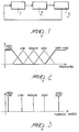
- the input is the pressure and the output is the speed whereto the motor must be brought.
- Figure 2 illustrates an example of fuzzy sets defined for the input pressure.
- the measured pressure value depends on the type of vacuum cleaner being used and in particular on the power of the electric motor. Said power is usually within the range between 0 and 5 psi.
- the output of the fuzzy system is the speed to be imparted to the turbine 2. This value has been characterized by using singletons rather than membership functions.
- Figure 3 illustrates the characterization of the speed of the turbine.
- Figures 2 and 3 describe the pressure and speed of the turbine merely from a qualitative point of view. Quantitatively, the values associated with the fuzzy sets are set as a function of the vacuum cleaner being used (system geometries, motor power).
- the above expert system thus allows to determine the type of floor being cleaned.
- the implemented algorithm is provided as follows.
- step 10 the device is brought to a fixed speed, referenced to as speed "p" in step 11.
- step 12 the pressure is measured and used in step 13 by the fuzzy expert system to obtain, step 14, a speed which is equal to the optimum speed the device must assume.
- the speed set by the fuzzy expert system is maintained until intense pressure variations are detected.
- step 15 intense pressure variations are detected, the algorithm goes from step 15 back to step 11, otherwise it returns to step 14 to maintain the speed at the determined optimum value.
- the second fuzzy expert system implemented in the controller 1 uses the pressure variation measurements to determine the standby mode, which leads to a reduction in the speed of the motor of the vacuum cleaner.
- the fuzzy system operates in an optimum manner when information related to the first derivative and to the second derivative of the pressure are used as input.
- the fuzzy sets related to said two input variables are of the type shown in Figure 5.
- the output variable allows to determine whether the system must continue to work or must be placed in standby mode. In the first case, the optimum speed determined by the first expert system is maintained; in the second case, the speed of the system is instead reduced to a minimum value.
- the motor cannot be switched off, since to bring the system out of standby mode it is necessary to detect a pressure variation, and this is possible only if a minimum flow of air is present.
- time-based hystereses are provided which allow the system to enter the standby condition only if said condition persists for a time T which is set during design.
- step 20 measures the first and second derivatives of the pressure detected by the pressure sensor 3 and then sends said measurements to the fuzzy expert system, designated by the reference numeral 21 in this case, which checks, during the step 22, whether the system is in standby or not.
- step 23 the speed of the turbine of the motor is set to the optimum value, step 23, and the algorithm returns to the step 20 for measuring the derivatives of the pressure.
- a step 24 is instead performed during which the algorithm waits for T seconds; at this point, the algorithm is executed in step 25, which is similar to step 22 and in which the standby mode of the system is checked. In this case too, if the response is negative, the algorithm moves on to a step 26, similar to step 23, and returns to step 20 from there.
- a step 27 is performed during which the speed of the turbine is set equal to a minimum value and the algorithm then returns to step 20.
- the above-described intelligent device can be split into three subsystems:
- the device according to the invention fully achieves the intended aim and objects, since it allows to automatically control the suction force of a vacuum cleaner, thus achieving optimization of the working setting and a consequent reduction in noise and energy consumption.
- This control is provided according to the conditions of the surface being cleaned. Without increasing the complexity and therefore the cost of the device, it is also possible to detect conditions or the non-use of the vacuum cleaner and place the system in standby until later reuse.
Landscapes
- Engineering & Computer Science (AREA)
- Physics & Mathematics (AREA)
- Artificial Intelligence (AREA)
- Mechanical Engineering (AREA)
- Software Systems (AREA)
- Automation & Control Theory (AREA)
- General Physics & Mathematics (AREA)
- Fuzzy Systems (AREA)
- Mathematical Physics (AREA)
- Fluid Mechanics (AREA)
- Health & Medical Sciences (AREA)
- Computer Vision & Pattern Recognition (AREA)
- Evolutionary Computation (AREA)
- Medical Informatics (AREA)
- Electric Vacuum Cleaner (AREA)
Abstract
An intelligent suction device particularly for vacuum
cleaners and the like, characterized in that it comprises a
fuzzy-logic controller (1) which is suitable to control the
motor of a turbine (2), the suction pressure whereof is
detected by at least one pressure sensor (3) which feeds
back its measurement, in a closed loop, to the controller
(1).


Description
The present invention relates to an intelligent
suction device capable of automatically adapting the
suction force according to the conditions of the surface,
particularly for vacuum cleaners and the like.
It is known that in a vacuum cleaner the suction force
is usually adjusted manually by the user according to the
surface that said user intends to clean. This system
generally has a potentiometer which allows to vary the
speed of the motor of the turbine of the vacuum cleaner.
In these systems, the user must therefore vary
manually the working setting of the vacuum cleaner
according to the type of surface to be cleaned.
Usually, the user uses the maximum speed of the
turbine needlessly; in these conditions, besides having a
high noise level, the energy consumption is higher than
necessary and is also not accompanied by improvements in
the resulting cleaning.
Moreover, when the user leaves the vacuum cleaner in
an inactive condition with the motor running, the suction
force does not decrease and therefore the turbine of the
vacuum cleaner continues to rotate at the rate set by the
user, also when for example the suction hose is not in
contact with the surface of the floor to be cleaned.
This entails therefore the drawback that energy
consumption is needlessly high and that the noise level is
highly unpleasant.
The aim of the present invention is therefore to
provide an intelligent suction device capable of
automatically adapting the suction force according to the
conditions of the surface to be cleaned.
Within the scope of this aim, an object of the present
invention is to provide an intelligent suction device
capable of automatically adapting the suction force
according to the conditions of the surface to be cleaned,
particularly for vacuum cleaners and the like, in which an
expert system for the constant and automatic control of the
working setting of the device is implemented.
Another object of the present invention is to provide
an intelligent suction device, particularly for vacuum
cleaners and the like, in which the energy consumption and
the noise level are always optimized.
Another object of the present invention is to provide
an intelligent suction device which can assume a standby
condition automatically when it is not used by the user
momentarily.
Another object of the present invention is to provide
an intelligent suction device, particularly for vacuum
cleaners and the like, in which the suction force is always
closely correlated to the type of surface to be cleaned.
Another object of the present invention is to provide
an intelligent suction device, particularly for vacuum
cleaners and the like, which is highly reliable and
relatively easy to provide at competitive costs.
This aim, these objects and others which will become
apparent hereinafter are achieved by an intelligent suction
device particularly for vacuum cleaners and the like,
characterized in that it comprises a fuzzy-logic controller
suitable to control the motor of a turbine, whose suction
pressure is detected by at least one pressure sensor which
feeds back its measurement, in a closed loop, to the
controller.
Further characteristics and advantages of the
invention will become apparent from the description of an
embodiment of the device according to the invention,
illustrated only by way of non-limitative example in the
accompanying drawings, wherein:
With reference to the above figures, the device
according to the present invention is provided as follows.
In a vacuum cleaner, the suction force is determined
by the difference in pressure between the internal part of
the system (low-pressure part) and the external part
(atmospheric-pressure part). Internal suction is produced
by means of a turbine which is driven by an electric motor.
In order to control the working setting, it is thus
fundamental to be able to measure the difference in
pressure between the inside and the outside of the vacuum
cleaner and to accordingly control the speed of the motor,
so as to adjust the suction force.
The device according to the invention is thus composed
of a controller 1 connected to a turbine 2 which is
connected to a pressure sensor that feeds back the detected
measurement to the controller 1.
The type of control explained above is shown in Figure
1.
The controller 1, on the basis of the pressure
measurements obtained by the pressure sensor 3, decides the
optimum speed to be applied to the motor of the turbine 2
in order to obtain the best working setting.
The controller 1 then implements an expert system
capable of deciding, on the basis of differential pressure
measurements, the optimum rotation rate of the turbine 2.
This result can be obtained because suction depends
highly on the type of floor being cleaned; in particular,
suction increases as the porosity of the floor increases.
For an equal rotation rate of the turbine 2, a carpet
produces a higher suction.
On the basis of this consideration, it is possible to
increase or decrease the speed of the motor automatically
as a function of the type of floor being cleaned.
By using said pressure measurement system, it is
possible to determine whether the vacuum cleaner is being
used or whether it has been left switched on but is not
being used. In these conditions it is in fact very
convenient to lower the motor speed in order to reduce the
noise and the energy consumption of the vacuum cleaner.
This result can be achieved by using the controller 1
used above, implementing a second expert system which is
capable of determining whether to put the device in standby
mode or not by means of pressure variation measurements.
For this second type of control it is important to
measure pressure variations rather than the differential
pressure. The pressure variation is in fact nil or very low
when the system is not used (for example when the suction
hose is in the air or left idle on the floor). By using the
same approach, it is also possible to determine whether the
suction duct is clogged: in these conditions, in fact, the
air flow in the turbine drops to almost zero and so do the
corresponding pressure variations.
The device is made to leave the standby mode when a
pressure variation that can be ascribed to the reuse of the
vacuum cleaner is detected.
All the expert systems implemented for controlling the
turbine of the vacuum cleaner have been provided with fuzzy
systems implemented with a microcontroller of the WARP 3
family. Of course, microcontrollers of another kind may
also be used.
The controller 1 thus implements two expert systems:
the first system is used for the optimum control of the
working setting of the vacuum cleaner, while the second
system is used to place the system in standby when the
vacuum cleaner is being used.
In the first expert system, the input is the pressure
and the output is the speed whereto the motor must be
brought.
Figure 2 illustrates an example of fuzzy sets defined
for the input pressure.
The measured pressure value depends on the type of
vacuum cleaner being used and in particular on the power of
the electric motor. Said power is usually within the range
between 0 and 5 psi.
The output of the fuzzy system is the speed to be
imparted to the turbine 2. This value has been
characterized by using singletons rather than membership
functions.
Figure 3 illustrates the characterization of the speed
of the turbine.
Figures 2 and 3 describe the pressure and speed of the
turbine merely from a qualitative point of view.
Quantitatively, the values associated with the fuzzy sets
are set as a function of the vacuum cleaner being used
(system geometries, motor power).
The rules used to implement the expert system are of
the following kind:
The above expert system thus allows to determine the
type of floor being cleaned. The implemented algorithm is
provided as follows.
At power-on, step 10, the device is brought to a fixed
speed, referenced to as speed "p" in step 11. During the
subsequent step 12, the pressure is measured and used in
step 13 by the fuzzy expert system to obtain, step 14, a
speed which is equal to the optimum speed the device must
assume.
The speed set by the fuzzy expert system is maintained
until intense pressure variations are detected.
If, step 15, intense pressure variations are detected,
the algorithm goes from step 15 back to step 11, otherwise
it returns to step 14 to maintain the speed at the
determined optimum value.
These steps are performed so as to avoid problems in
determining the type of floor. Characterization of the
system is in fact performed in a laboratory by using a
specific rotation rate of the motor (speed = "p").
Together with this speed, pressure values related to
different types of floor (parquet, marble, fitted carpet,
etcetera) are detected.
For this reason it is necessary, during the step for
determining the optimum working setting, to bring the
system to the reference speed (speed = "p"), since
classification of the type of floor is valid only if the
measurement conditions are the same as those used during
the system characterization step.
The second fuzzy expert system implemented in the
controller 1 uses the pressure variation measurements to
determine the standby mode, which leads to a reduction in
the speed of the motor of the vacuum cleaner.
In this case, the fuzzy system operates in an optimum
manner when information related to the first derivative and
to the second derivative of the pressure are used as input.
The fuzzy sets related to said two input variables are
of the type shown in Figure 5.
The output variable allows to determine whether the
system must continue to work or must be placed in standby
mode. In the first case, the optimum speed determined by
the first expert system is maintained; in the second case,
the speed of the system is instead reduced to a minimum
value.
The motor cannot be switched off, since to bring the
system out of standby mode it is necessary to detect a
pressure variation, and this is possible only if a minimum
flow of air is present.
The rules used by this second fuzzy expert system
implemented in the controller 1 are of the following type:
IF first derivative of pressure IS VERY LOW AND second
derivative of pressure IS VERY LOW THEN system state IS
standby
IF first derivative of pressure IS VERY LOW AND second
derivative of pressure IS LOW THEN system state IS standby
IF first derivative of pressure IS LOW AND second
derivative of pressure IS VERY LOW THEN system state IS
standby
IF first derivative of pressure IS HIGH AND second derivative of pressure IS VERY HIGH THEN system state IS working mode.
IF first derivative of pressure IS HIGH AND second derivative of pressure IS VERY HIGH THEN system state IS working mode.
In order to avoid oscillation in determining the state
of the system, time-based hystereses are provided which
allow the system to enter the standby condition only if
said condition persists for a time T which is set during
design.
The algorithm that determines the behavior of the
device in standby conditions is shown in Figure 7, wherein
the step 20 measures the first and second derivatives of
the pressure detected by the pressure sensor 3 and then
sends said measurements to the fuzzy expert system,
designated by the reference numeral 21 in this case, which
checks, during the step 22, whether the system is in
standby or not.
In case of a negative response, the speed of the
turbine of the motor is set to the optimum value, step 23,
and the algorithm returns to the step 20 for measuring the
derivatives of the pressure.
In case of a positive response, a step 24 is instead
performed during which the algorithm waits for T seconds;
at this point, the algorithm is executed in step 25, which
is similar to step 22 and in which the standby mode of the
system is checked. In this case too, if the response is
negative, the algorithm moves on to a step 26, similar to
step 23, and returns to step 20 from there. In case of
positive response, instead, a step 27 is performed during
which the speed of the turbine is set equal to a minimum
value and the algorithm then returns to step 20.
The above-described intelligent device can be split
into three subsystems:
Implementation of the expert systems requires the use
of a microcontroller which, by means of the information
arriving from the pressure sensor 4, which is of the
differential type, is able to determine the optimum working
setting. As mentioned, it is possible to use for example
the microcontroller of the WARP 3 family.
In practice, it has been observed that the device
according to the invention fully achieves the intended aim
and objects, since it allows to automatically control the
suction force of a vacuum cleaner, thus achieving
optimization of the working setting and a consequent
reduction in noise and energy consumption. This control is
provided according to the conditions of the surface being
cleaned. Without increasing the complexity and therefore
the cost of the device, it is also possible to detect
conditions or the non-use of the vacuum cleaner and place
the system in standby until later reuse.
The device thus conceived is susceptible of numerous
modifications and variations, all of which are within the
scope of the inventive concept; all the details may also be
replaced with other technically equivalent elements.
Where technical features mentioned in any claim are
followed by reference signs, those reference signs have
been included for the sole purpose of increasing the
intelligibility of the claims and accordingly such
reference signs do not have any limiting effect on the
interpretation of each element identified by way of example
by such reference signs.
Claims (13)
- An intelligent suction device particularly for vacuum cleaners and the like, characterized in that it comprises a fuzzy-logic controller which is suitable to control the motor of a turbine, the suction pressure whereof is detected by at least one pressure sensor which feeds back its measurement, in a closed loop, to the controller.
- A device according to claim 1, characterized in that said controller comprises a first expert system which is provided in fuzzy logic for the optimum control of the working setting.
- A device according to claim 1, characterized in that said controller comprises a second expert system which is provided in fuzzy logic to control the standby condition of the device.
- A device according to one or more of the preceding claims, characterized in that in said first expert system, the input is the pressure detected by said pressure sensor and the output is a speed level whereto said turbine motor must be brought.
- A device according to one or more of the preceding claims, characterized in that said turbine speed level is characterized by using singletons.
- A device according to one or more of the preceding claims, characterized in that said first expert system detects pressure variations measured by said pressure sensor in order to determine a speed value for the motor of said turbine.
- A device according to one or more of the preceding claims, characterized in that in said second expert system, the input is the first derivative and the second derivative of the pressure value detected by said pressure sensor and the output is the state of the device.
- A device according to one or more of the preceding claims, characterized in that speed control of said turbine is provided by means of a triac.
- A device according to one or more of the preceding claims, characterized in that said pressure sensor is a sensor of the piezoresistive type.
- A method for controlling the suction force, particularly for a vacuum cleaner and the like, wherein the suction is provided by means of a motorized turbine, characterized in that it comprises the steps of:measuring the pressure difference between the part inside the vacuum cleaner and the outside of the vacuum cleaner;controlling the speed of the turbine motor according to said pressure difference.
- A method according to claim 10, characterized in that the step that consists in controlling the speed of said turbine comprises the steps of:bringing the turbine motor to a fixed speed;using the pressure value measured by the pressure sensor by means of a first fuzzy expert system;maintaining a speed value which is determined by said fuzzy expert system until pressure variations are detected.
- A method according to one or more of the preceding claims, characterized in that it comprises the step of determining the state of the device.
- A method according to claim 12, characterized in that said step that consists in determining the state of the device comprises the measurement of derivatives of the pressure detected by said pressure sensor;sending the resulting measurements to a second fuzzy expert system;determining the state of the device on the basis of said pressure derivatives;if the system is in standby mode, waiting for a preset time before confirming the standby state and setting the speed of the turbine motor to a minimum value.
Priority Applications (4)
| Application Number | Priority Date | Filing Date | Title |
|---|---|---|---|
| EP98830041A EP0933058A1 (en) | 1998-01-30 | 1998-01-30 | Intelligent suction device capable of automatically adapting the suction force according to the conditions of the surface, particularly for vacuum cleaners and the like |
| US09/236,786 US6105202A (en) | 1998-01-30 | 1999-01-25 | Intelligent suction device capable of automatically adapting the suction force according to the conditions of the surface, particularly for vacuum cleaners and the like |
| JP11021646A JPH11267076A (en) | 1998-01-30 | 1999-01-29 | Intelligent suction device and method for controlling suction force of suction device |
| US09/514,972 US6255792B1 (en) | 1998-01-30 | 2000-02-29 | Intelligent suction device capable of automatically adapting the suction force according to the conditions of the surface, particularly for vacuum cleaners and the like |
Applications Claiming Priority (1)
| Application Number | Priority Date | Filing Date | Title |
|---|---|---|---|
| EP98830041A EP0933058A1 (en) | 1998-01-30 | 1998-01-30 | Intelligent suction device capable of automatically adapting the suction force according to the conditions of the surface, particularly for vacuum cleaners and the like |
Publications (1)
| Publication Number | Publication Date |
|---|---|
| EP0933058A1 true EP0933058A1 (en) | 1999-08-04 |
Family
ID=8236528
Family Applications (1)
| Application Number | Title | Priority Date | Filing Date |
|---|---|---|---|
| EP98830041A Withdrawn EP0933058A1 (en) | 1998-01-30 | 1998-01-30 | Intelligent suction device capable of automatically adapting the suction force according to the conditions of the surface, particularly for vacuum cleaners and the like |
Country Status (3)
| Country | Link |
|---|---|
| US (2) | US6105202A (en) |
| EP (1) | EP0933058A1 (en) |
| JP (1) | JPH11267076A (en) |
Cited By (1)
| Publication number | Priority date | Publication date | Assignee | Title |
|---|---|---|---|---|
| WO2002091899A1 (en) * | 2001-05-15 | 2002-11-21 | Arçelik A.S. | A control method for a vacuum cleaner |
Families Citing this family (29)
| Publication number | Priority date | Publication date | Assignee | Title |
|---|---|---|---|---|
| US6457205B1 (en) | 2000-05-24 | 2002-10-01 | Fantom Technologies Inc. | Vacuum cleaner having a plurality of power modes |
| WO2003026474A2 (en) * | 2001-09-26 | 2003-04-03 | Friendly Robotics Ltd. | Robotic vacuum cleaner |
| IL145680A0 (en) | 2001-09-26 | 2002-06-30 | Friendly Robotics Ltd | Robotic vacuum cleaner |
| ES2382653T3 (en) * | 2002-05-22 | 2012-06-12 | Panasonic Corporation | Vacuum cleaner and suction nozzle used in it |
| US7712182B2 (en) | 2003-07-25 | 2010-05-11 | Milwaukee Electric Tool Corporation | Air flow-producing device, such as a vacuum cleaner or a blower |
| US7237298B2 (en) * | 2003-09-19 | 2007-07-03 | Royal Appliance Mfg. Co. | Sensors and associated methods for controlling a vacuum cleaner |
| US7629695B2 (en) * | 2004-05-20 | 2009-12-08 | Kabushiki Kaisha Toshiba | Stacked electronic component and manufacturing method thereof |
| US7449830B2 (en) | 2004-08-02 | 2008-11-11 | Lg Display Co., Ltd. | OLEDs having improved luminance stability |
| US7449831B2 (en) * | 2004-08-02 | 2008-11-11 | Lg Display Co., Ltd. | OLEDs having inorganic material containing anode capping layer |
| US8487527B2 (en) * | 2005-05-04 | 2013-07-16 | Lg Display Co., Ltd. | Organic light emitting devices |
| US7777407B2 (en) * | 2005-05-04 | 2010-08-17 | Lg Display Co., Ltd. | Organic light emitting devices comprising a doped triazine electron transport layer |
| US20060265278A1 (en) * | 2005-05-18 | 2006-11-23 | Napster Llc | System and method for censoring randomly generated character strings |
| US7728517B2 (en) | 2005-05-20 | 2010-06-01 | Lg Display Co., Ltd. | Intermediate electrodes for stacked OLEDs |
| US7795806B2 (en) | 2005-05-20 | 2010-09-14 | Lg Display Co., Ltd. | Reduced reflectance display devices containing a thin-layer metal-organic mixed layer (MOML) |
| US7811679B2 (en) * | 2005-05-20 | 2010-10-12 | Lg Display Co., Ltd. | Display devices with light absorbing metal nanoparticle layers |
| US7750561B2 (en) * | 2005-05-20 | 2010-07-06 | Lg Display Co., Ltd. | Stacked OLED structure |
| US7943244B2 (en) * | 2005-05-20 | 2011-05-17 | Lg Display Co., Ltd. | Display device with metal-organic mixed layer anodes |
| US8182611B2 (en) * | 2006-03-30 | 2012-05-22 | Yoo Byung-Sun | Vacuum cleaning apparatus and cleaning method thereof |
| CN100425191C (en) * | 2006-05-24 | 2008-10-15 | 宁波富达电器有限公司 | Air pressure sensing vacuum cleaner |
| DE102007057589B4 (en) * | 2007-11-28 | 2010-09-30 | BSH Bosch und Siemens Hausgeräte GmbH | Air volumetric flow and pusher force control device |
| KR100946719B1 (en) * | 2007-11-28 | 2010-03-12 | 영 춘 정 | Apparatus to control a multi programmable constant air flow with speed controllable brushless motor |
| DE102011006541A1 (en) * | 2011-03-31 | 2012-10-04 | BSH Bosch und Siemens Hausgeräte GmbH | Vacuum cleaner and method for suction pressure-dependent operation of a vacuum cleaner |
| EP2510857A1 (en) * | 2011-04-14 | 2012-10-17 | Koninklijke Philips Electronics N.V. | Vacuum cleaning device |
| DE102011052020A1 (en) | 2011-07-21 | 2013-01-24 | Miele & Cie. Kg | Vacuum cleaner and method for operating a vacuum cleaner |
| JP6052828B2 (en) * | 2015-07-20 | 2016-12-27 | レイコップ・コリア株式会社 | Cleaning efficiency control device for cleaning machine according to type of cleaning object and control method thereof |
| KR20170030197A (en) * | 2015-09-09 | 2017-03-17 | 레이캅코리아 주식회사 | Cleaner that driving power for surface of cleaning object is secured |
| EP3241476A1 (en) * | 2016-05-03 | 2017-11-08 | Koninklijke Philips N.V. | Vacuum cleaner |
| EP3740109A1 (en) | 2018-01-17 | 2020-11-25 | Techtronic Floor Care Technology Limited | System and method for operating a cleaning system based on a surface to be cleaned |
| FR3088395B1 (en) * | 2018-11-08 | 2020-11-20 | Tallano Tech | OPTIMIZED BRAKE PARTICLE SUCTION SYSTEM |
Citations (6)
| Publication number | Priority date | Publication date | Assignee | Title |
|---|---|---|---|---|
| EP0451787A1 (en) * | 1990-04-10 | 1991-10-16 | Matsushita Electric Industrial Co., Ltd. | Vacuum cleaner with fuzzy control |
| EP0479609A2 (en) * | 1990-10-05 | 1992-04-08 | Hitachi, Ltd. | Vacuum cleaner and control method thereof |
| EP0488884A1 (en) * | 1990-11-26 | 1992-06-03 | Matsushita Electric Industrial Co., Ltd. | Vacuum cleaner |
| EP0488883A2 (en) * | 1990-11-26 | 1992-06-03 | Matsushita Electric Industrial Co., Ltd. | Control apparatus of an electrical appliance |
| EP0527567A2 (en) * | 1991-08-01 | 1993-02-17 | Hitachi, Ltd. | A method of controlling a controlled object, and a control system for such a method |
| DE4304263C1 (en) * | 1993-02-12 | 1994-04-21 | Siemens Ag | Suction appts for loading-unloading of bulk material in large scale transportation or for domestic and industrial vacuum cleaner - uses fuzzy-logic control and has dust sensor deflecting loading of air with particles and producing signal proportional to loading |
Family Cites Families (7)
| Publication number | Priority date | Publication date | Assignee | Title |
|---|---|---|---|---|
| FR2541945B1 (en) * | 1983-03-04 | 1987-08-21 | Loubet Eliane | AIR CONDITIONER FOR WORKING CABINS IN POLLUTED ATMOSPHERE |
| JPH074335B2 (en) * | 1990-07-17 | 1995-01-25 | 三菱電機ホーム機器株式会社 | Vacuum cleaner |
| US5255409A (en) * | 1990-07-18 | 1993-10-26 | Sanyo Electric Co., Ltd. | Electric vacuum cleaner having an electric blower driven in accordance with the conditions of floor surfaces |
| JPH0824654B2 (en) * | 1990-09-14 | 1996-03-13 | 松下電器産業株式会社 | Electric vacuum cleaner |
| JPH04309319A (en) * | 1991-04-09 | 1992-10-30 | Matsushita Electric Ind Co Ltd | Cleaner |
| FR2708188A1 (en) * | 1993-07-28 | 1995-02-03 | Philips Laboratoire Electroniq | Vacuum cleaner with means of soil detection and adjustment of the engine power according to the detected soil. |
| ES2125026T3 (en) * | 1994-07-13 | 1999-02-16 | Moulinex Sa | DUST VACUUMS COMPRISING A DIFFUSE LOGIC CONTROL UNIT. |
-
1998
- 1998-01-30 EP EP98830041A patent/EP0933058A1/en not_active Withdrawn
-
1999
- 1999-01-25 US US09/236,786 patent/US6105202A/en not_active Expired - Fee Related
- 1999-01-29 JP JP11021646A patent/JPH11267076A/en not_active Withdrawn
-
2000
- 2000-02-29 US US09/514,972 patent/US6255792B1/en not_active Expired - Lifetime
Patent Citations (6)
| Publication number | Priority date | Publication date | Assignee | Title |
|---|---|---|---|---|
| EP0451787A1 (en) * | 1990-04-10 | 1991-10-16 | Matsushita Electric Industrial Co., Ltd. | Vacuum cleaner with fuzzy control |
| EP0479609A2 (en) * | 1990-10-05 | 1992-04-08 | Hitachi, Ltd. | Vacuum cleaner and control method thereof |
| EP0488884A1 (en) * | 1990-11-26 | 1992-06-03 | Matsushita Electric Industrial Co., Ltd. | Vacuum cleaner |
| EP0488883A2 (en) * | 1990-11-26 | 1992-06-03 | Matsushita Electric Industrial Co., Ltd. | Control apparatus of an electrical appliance |
| EP0527567A2 (en) * | 1991-08-01 | 1993-02-17 | Hitachi, Ltd. | A method of controlling a controlled object, and a control system for such a method |
| DE4304263C1 (en) * | 1993-02-12 | 1994-04-21 | Siemens Ag | Suction appts for loading-unloading of bulk material in large scale transportation or for domestic and industrial vacuum cleaner - uses fuzzy-logic control and has dust sensor deflecting loading of air with particles and producing signal proportional to loading |
Cited By (1)
| Publication number | Priority date | Publication date | Assignee | Title |
|---|---|---|---|---|
| WO2002091899A1 (en) * | 2001-05-15 | 2002-11-21 | Arçelik A.S. | A control method for a vacuum cleaner |
Also Published As
| Publication number | Publication date |
|---|---|
| US6105202A (en) | 2000-08-22 |
| US6255792B1 (en) | 2001-07-03 |
| JPH11267076A (en) | 1999-10-05 |
Similar Documents
| Publication | Publication Date | Title |
|---|---|---|
| EP0933058A1 (en) | Intelligent suction device capable of automatically adapting the suction force according to the conditions of the surface, particularly for vacuum cleaners and the like | |
| KR100443091B1 (en) | A power-controlled vacuum cleaner according to the operation mode of the electric brush | |
| US5722109A (en) | Vacuum cleaner with floor type detection means and motor power control as a function of the detected floor type | |
| KR930000101B1 (en) | Electric vacuum cleaner | |
| US4958406A (en) | Method and apparatus for operating vacuum cleaner | |
| KR0161987B1 (en) | Method for operating a vacuum cleaner | |
| RU2489075C2 (en) | Device for automatic adjustment of vacuum cleaner suction capacity | |
| US7026771B2 (en) | Motor control apparatus and electric appliance using the same | |
| KR100261622B1 (en) | A method of controlling a controlled object, and a control system for such a method | |
| JPH0910153A (en) | Electric vacuum cleaner | |
| JP2002028117A (en) | Vacuum cleaner | |
| EP1389059B1 (en) | A control method for a vacuum cleaner | |
| JPH0759697A (en) | Vacuum cleaner | |
| JP2889687B2 (en) | Electric vacuum cleaner | |
| JP3453845B2 (en) | Electric vacuum cleaner | |
| JP2969729B2 (en) | Electric vacuum cleaner | |
| JPH04144527A (en) | Vacuum cleaner | |
| KR960001807B1 (en) | Control apparatus for a vacuum cleaner and the method thereof | |
| JPH02180236A (en) | Control device of vacuum cleaner | |
| JPH0556898A (en) | Controller for household electric appliance and controller for vacuum cleaner or washing-machine | |
| JP2755866B2 (en) | Electric vacuum cleaner | |
| KR970005516B1 (en) | Method and device for controlling the power source responding to the dust in a vacuum cleaner | |
| JPH04250126A (en) | Vacuum cleaner | |
| JPH0458930A (en) | Vacuum cleaner | |
| KR960007468B1 (en) | Apparatus and method for switching pressure sensor level detector and for detecting operational error for a vacuum cleaner |
Legal Events
| Date | Code | Title | Description |
|---|---|---|---|
| PUAI | Public reference made under article 153(3) epc to a published international application that has entered the european phase |
Free format text: ORIGINAL CODE: 0009012 |
|
| AK | Designated contracting states |
Kind code of ref document: A1 Designated state(s): DE FR GB IT |
|
| AX | Request for extension of the european patent |
Free format text: AL;LT;LV;MK;RO;SI |
|
| 17P | Request for examination filed |
Effective date: 20000126 |
|
| AKX | Designation fees paid |
Free format text: DE FR GB IT |
|
| STAA | Information on the status of an ep patent application or granted ep patent |
Free format text: STATUS: THE APPLICATION HAS BEEN WITHDRAWN |
|
| 18W | Application withdrawn |
Effective date: 20051130 |