EP0927954A2 - Image signal compression coding method and apparatus - Google Patents
Image signal compression coding method and apparatus Download PDFInfo
- Publication number
- EP0927954A2 EP0927954A2 EP19980113007 EP98113007A EP0927954A2 EP 0927954 A2 EP0927954 A2 EP 0927954A2 EP 19980113007 EP19980113007 EP 19980113007 EP 98113007 A EP98113007 A EP 98113007A EP 0927954 A2 EP0927954 A2 EP 0927954A2
- Authority
- EP
- European Patent Office
- Prior art keywords
- field
- data
- image signal
- frames
- compression coding
- Prior art date
- Legal status (The legal status is an assumption and is not a legal conclusion. Google has not performed a legal analysis and makes no representation as to the accuracy of the status listed.)
- Granted
Links
Images


Classifications
-
- H—ELECTRICITY
- H04—ELECTRIC COMMUNICATION TECHNIQUE
- H04N—PICTORIAL COMMUNICATION, e.g. TELEVISION
- H04N19/00—Methods or arrangements for coding, decoding, compressing or decompressing digital video signals
- H04N19/50—Methods or arrangements for coding, decoding, compressing or decompressing digital video signals using predictive coding
- H04N19/503—Methods or arrangements for coding, decoding, compressing or decompressing digital video signals using predictive coding involving temporal prediction
- H04N19/51—Motion estimation or motion compensation
-
- H—ELECTRICITY
- H04—ELECTRIC COMMUNICATION TECHNIQUE
- H04N—PICTORIAL COMMUNICATION, e.g. TELEVISION
- H04N19/00—Methods or arrangements for coding, decoding, compressing or decompressing digital video signals
- H04N19/10—Methods or arrangements for coding, decoding, compressing or decompressing digital video signals using adaptive coding
- H04N19/134—Methods or arrangements for coding, decoding, compressing or decompressing digital video signals using adaptive coding characterised by the element, parameter or criterion affecting or controlling the adaptive coding
- H04N19/146—Data rate or code amount at the encoder output
- H04N19/152—Data rate or code amount at the encoder output by measuring the fullness of the transmission buffer
-
- H—ELECTRICITY
- H04—ELECTRIC COMMUNICATION TECHNIQUE
- H04N—PICTORIAL COMMUNICATION, e.g. TELEVISION
- H04N19/00—Methods or arrangements for coding, decoding, compressing or decompressing digital video signals
- H04N19/10—Methods or arrangements for coding, decoding, compressing or decompressing digital video signals using adaptive coding
- H04N19/102—Methods or arrangements for coding, decoding, compressing or decompressing digital video signals using adaptive coding characterised by the element, parameter or selection affected or controlled by the adaptive coding
- H04N19/103—Selection of coding mode or of prediction mode
- H04N19/105—Selection of the reference unit for prediction within a chosen coding or prediction mode, e.g. adaptive choice of position and number of pixels used for prediction
-
- H—ELECTRICITY
- H04—ELECTRIC COMMUNICATION TECHNIQUE
- H04N—PICTORIAL COMMUNICATION, e.g. TELEVISION
- H04N19/00—Methods or arrangements for coding, decoding, compressing or decompressing digital video signals
- H04N19/10—Methods or arrangements for coding, decoding, compressing or decompressing digital video signals using adaptive coding
- H04N19/102—Methods or arrangements for coding, decoding, compressing or decompressing digital video signals using adaptive coding characterised by the element, parameter or selection affected or controlled by the adaptive coding
- H04N19/124—Quantisation
-
- H—ELECTRICITY
- H04—ELECTRIC COMMUNICATION TECHNIQUE
- H04N—PICTORIAL COMMUNICATION, e.g. TELEVISION
- H04N19/00—Methods or arrangements for coding, decoding, compressing or decompressing digital video signals
- H04N19/10—Methods or arrangements for coding, decoding, compressing or decompressing digital video signals using adaptive coding
- H04N19/134—Methods or arrangements for coding, decoding, compressing or decompressing digital video signals using adaptive coding characterised by the element, parameter or criterion affecting or controlling the adaptive coding
- H04N19/136—Incoming video signal characteristics or properties
- H04N19/137—Motion inside a coding unit, e.g. average field, frame or block difference
-
- H—ELECTRICITY
- H04—ELECTRIC COMMUNICATION TECHNIQUE
- H04N—PICTORIAL COMMUNICATION, e.g. TELEVISION
- H04N19/00—Methods or arrangements for coding, decoding, compressing or decompressing digital video signals
- H04N19/10—Methods or arrangements for coding, decoding, compressing or decompressing digital video signals using adaptive coding
- H04N19/169—Methods or arrangements for coding, decoding, compressing or decompressing digital video signals using adaptive coding characterised by the coding unit, i.e. the structural portion or semantic portion of the video signal being the object or the subject of the adaptive coding
- H04N19/17—Methods or arrangements for coding, decoding, compressing or decompressing digital video signals using adaptive coding characterised by the coding unit, i.e. the structural portion or semantic portion of the video signal being the object or the subject of the adaptive coding the unit being an image region, e.g. an object
- H04N19/172—Methods or arrangements for coding, decoding, compressing or decompressing digital video signals using adaptive coding characterised by the coding unit, i.e. the structural portion or semantic portion of the video signal being the object or the subject of the adaptive coding the unit being an image region, e.g. an object the region being a picture, frame or field
-
- H—ELECTRICITY
- H04—ELECTRIC COMMUNICATION TECHNIQUE
- H04N—PICTORIAL COMMUNICATION, e.g. TELEVISION
- H04N19/00—Methods or arrangements for coding, decoding, compressing or decompressing digital video signals
- H04N19/50—Methods or arrangements for coding, decoding, compressing or decompressing digital video signals using predictive coding
- H04N19/593—Methods or arrangements for coding, decoding, compressing or decompressing digital video signals using predictive coding involving spatial prediction techniques
-
- H—ELECTRICITY
- H04—ELECTRIC COMMUNICATION TECHNIQUE
- H04N—PICTORIAL COMMUNICATION, e.g. TELEVISION
- H04N19/00—Methods or arrangements for coding, decoding, compressing or decompressing digital video signals
- H04N19/60—Methods or arrangements for coding, decoding, compressing or decompressing digital video signals using transform coding
- H04N19/61—Methods or arrangements for coding, decoding, compressing or decompressing digital video signals using transform coding in combination with predictive coding
-
- H—ELECTRICITY
- H04—ELECTRIC COMMUNICATION TECHNIQUE
- H04N—PICTORIAL COMMUNICATION, e.g. TELEVISION
- H04N19/00—Methods or arrangements for coding, decoding, compressing or decompressing digital video signals
- H04N19/70—Methods or arrangements for coding, decoding, compressing or decompressing digital video signals characterised by syntax aspects related to video coding, e.g. related to compression standards
-
- H—ELECTRICITY
- H04—ELECTRIC COMMUNICATION TECHNIQUE
- H04N—PICTORIAL COMMUNICATION, e.g. TELEVISION
- H04N19/00—Methods or arrangements for coding, decoding, compressing or decompressing digital video signals
- H04N19/10—Methods or arrangements for coding, decoding, compressing or decompressing digital video signals using adaptive coding
- H04N19/134—Methods or arrangements for coding, decoding, compressing or decompressing digital video signals using adaptive coding characterised by the element, parameter or criterion affecting or controlling the adaptive coding
- H04N19/146—Data rate or code amount at the encoder output
Definitions
- the present invention relates to a progressive image signal compression coding method and apparatus, and more particularly, to a method and apparatus for compression-coding a frame divided into fields in which each field is processed using data only from itself, and fields in which each field is processed using a differential component between two fields within one frame.
- a conventional image signal compression coding method is performed using frames as basic units, that is, intra (I) frames in which each frame is compression-coded using information only from itself, predicted (P) frames in which a differential component detected from the previous I or P frames temporally preceding the present frame are compression-coded, and bidirectional predicted (B) frames in which a differential component detected from the previous I or P pictures or the following I or P pictures are compression-coded.
- I intra
- P predicted
- B bidirectional predicted
- output data is formed using inter-frame information using frames as basic units.
- the intra-frame data information cannot be utilized.
- an objective of the present invention to provide an image signal compression coding method for coding one field by coding data from only that field, and coding the other field by coding a differential component between two fields within one frame.
- an image signal compression coding method comprising the steps of (a) compression-coding one field of an input progressive image signal composed of frames, using only data from that field, and (b) compression-coding the other field using differential data between the previous field and that field.
- an image signal compression coding apparatus comprising a pre-processor for outputting data of one field of an input progressive image signal composed of frames as it is, and outputting the other field as differential data between that field and the previous field, and a coder for generating coded data by performing compression coding on the output of the pre-processor.
- FIG. 1 is a block diagram of an image signal compression coder adopted by a general digital video recording/playback apparatus.
- DCT discrete cosine transform
- the quantizer 104 quantizes and compresses the DCT coefficients according to a quantization step size adjusted by a fixed bitrate for each frame, output from a bitrate controller 110.
- a variable length coder (VLC)106 variable-length codes the quantized coefficients supplied from the quantizer 104, and the variable-length coded data is temporarily stored in a buffer 108.
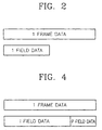
- FIG. 2 shows the amount of output data of the compression coder shown in FIG. 1.
- the bitrates are fixed in units of frames. Thus, when the frame-based processing result is fixed to a predetermined amount, the data of one field is half of one frame.
- FIG. 3 is a block diagram of an image signal compression coder according to the present invention, in which compression coding is performed using a correlation of data between fields within one frame.
- a progressive image signal composed of frames is input in units of fields, and field data is simultaneously applied to a field memory 202 and a first input port of a selector 206.
- a subtractor 204 subtracts the previous field data stored in the field memory 202 from input field data, and applies a differential component to a second input port of the selector 206.
- the selector 206 selects data of one field currently being applied to the first input port, and applies the selected data to the DCT processor 208 to perform compression coding.
- This is the same as the compression coding performed by the compression coder shown in FIG. 1, except that the processing unit is not a frame but a field.
- the selector 206 applies a differential component between two fields within one frame to the DCT processor 208 to perform compression coding only on the differential component.
- the DCT processor 208 DCT-processes the data selected by the selector 206 and applies DCT coefficients of a frequency domain to a quantizer 210.
- the quantizer 210 quantizes and compresses the DCT coefficients according to a quantization step size adjusted by a fixed bitrate for each frame, output from a bitrate controller 216.
- the quantization step size used in the present invention is smaller than that used by the compression coder shown in FIG. 1, when the fixed bitrate for each frame is the same as that of the compression coder shown in FIG. 1.
- a larger amount of coded data can be allocated for one field than in the case of frame-based compression coding.
- variable length coder 212 variable-length codes the quantized coefficients supplied from the quantizer 210, and the variable-length coded data is temporarily stored in a buffer 214.
- a bitrate controller 216 adjusts the quantization step size so that the bitrate of the data stored in the buffer 214 does not exceed the fixed bitrate for each frame.
- the field memory 202, the subtractor 204 and the selector 206 can be designated as a pre-processor.
- the other blocks shown in FIG. 3, including the DCT processor, through the bitrate controller 208 - 216 and so on, can be designated as a coder, which is described here only as an illustrative embodiment, as many other applications are possible.
- the bit amount of the field in which only the data from itself is processed is larger than that of the field in which an inter-field differential component is processed (indicated by P field data).
- FIGS. 5A and 5B show the format of data input to the image signal compression coder according to the present invention.
- FIG. 5A shows the image composed of frames
- FIG. 5B shows the format of input data divided into fields.
- the image signal compression coding method of the present invention if a progressive image signal composed of frames is input in units of fields, the input signal is compression-coded such that one field is compression-coded using only data from itself, and the other field is compression-coded using differential data between the previous field and the present field (without consideration of a motion vector), based on the characteristics of the input progressive image signal composed of frames. In such a manner, the amount of output data of the other field can be considerably reduced so that the amount of output data of one field increases.
- compression coding is performed in units of fields such that one field is compression-coded using data from only that field, and the other field is compression-coded using differential data between two fields within one frame, thereby enabling a high resolution image signal to be processed.
Landscapes
- Engineering & Computer Science (AREA)
- Multimedia (AREA)
- Signal Processing (AREA)
- Compression Or Coding Systems Of Tv Signals (AREA)
Abstract
Description
- The present invention relates to a progressive image signal compression coding method and apparatus, and more particularly, to a method and apparatus for compression-coding a frame divided into fields in which each field is processed using data only from itself, and fields in which each field is processed using a differential component between two fields within one frame.
- A conventional image signal compression coding method is performed using frames as basic units, that is, intra (I) frames in which each frame is compression-coded using information only from itself, predicted (P) frames in which a differential component detected from the previous I or P frames temporally preceding the present frame are compression-coded, and bidirectional predicted (B) frames in which a differential component detected from the previous I or P pictures or the following I or P pictures are compression-coded.
- As described above, in the conventional image signal compression coding method, output data is formed using inter-frame information using frames as basic units. However, although such a compression coding method is useful in forming the output data using the inter-frame data information, the intra-frame data information cannot be utilized.
- To solve the above problem, it is an objective of the present invention to provide an image signal compression coding method for coding one field by coding data from only that field, and coding the other field by coding a differential component between two fields within one frame.
- It is another objective of the present invention to provide an image signal compression coding apparatus for coding one field by coding data from only that field, and coding the other field by coding a differential component between two fields within one frame.
- Accordingly, to achieve the first objective, there is provided an image signal compression coding method comprising the steps of (a) compression-coding one field of an input progressive image signal composed of frames, using only data from that field, and (b) compression-coding the other field using differential data between the previous field and that field.
- To achieve the second objective, there is provided an image signal compression coding apparatus comprising a pre-processor for outputting data of one field of an input progressive image signal composed of frames as it is, and outputting the other field as differential data between that field and the previous field, and a coder for generating coded data by performing compression coding on the output of the pre-processor.
- The above objectives and advantages of the present invention will become more apparent by describing in detail a preferred embodiment thereof with reference to the attached drawings in which:
- FIG. 1 is a block diagram of an image signal compression coder adopted by a general digital video recording/playback apparatus;
- FIG. 2 shows the amount of output data of the image signal compression coder shown in FIG. 1;
- FIG. 3 is a block diagram of an image signal compression coder according to the present invention;
- FIG. 4 shows the amount of output data of the image signal compression coder shown in FIG. 3; and
- FIGS. 5A and 5B show the format of data input to the image signal compression coder shown in FIG. 3.
-
- Hereinbelow, an image signal compression coding method and apparatus according to a preferred embodiment of the present invention will be described with reference to the accompanying drawings.
- When a compression coding method is actually applied to a digital recording/playback apparatus, P frames and B frames using motion vectors between frames are not used often considering convenience of signal processing and trick play, and usually only I frames based on one frame are used. FIG. 1 is a block diagram of an image signal compression coder adopted by a general digital video recording/playback apparatus.
- In FIG. 1, when a progressive image signal composed of frames is applied to a discrete cosine transform (DCT)
processor 102, theDCT processor 102 DCT-processes the progressive image signal in units of DCT blocks (8 pixels × 8 lines) and applies DCT coefficients of a frequency domain to aquantizer 104. - The
quantizer 104 quantizes and compresses the DCT coefficients according to a quantization step size adjusted by a fixed bitrate for each frame, output from abitrate controller 110. A variable length coder (VLC)106 variable-length codes the quantized coefficients supplied from thequantizer 104, and the variable-length coded data is temporarily stored in abuffer 108. - FIG. 2 shows the amount of output data of the compression coder shown in FIG. 1. The bitrates are fixed in units of frames. Thus, when the frame-based processing result is fixed to a predetermined amount, the data of one field is half of one frame.
- Thus, in the conventional compression coder in which inter-frame data information based on a motion vector is used and the general compression coder shown in FIG. 1, intra-frame data information is not used at all.
- FIG. 3 is a block diagram of an image signal compression coder according to the present invention, in which compression coding is performed using a correlation of data between fields within one frame. In FIG. 3, a progressive image signal composed of frames is input in units of fields, and field data is simultaneously applied to a
field memory 202 and a first input port of aselector 206. - A
subtractor 204 subtracts the previous field data stored in thefield memory 202 from input field data, and applies a differential component to a second input port of theselector 206. - According to the field discrimination signal, in the case of a field (e.g., a first field or an odd field) of a frame, the
selector 206 selects data of one field currently being applied to the first input port, and applies the selected data to theDCT processor 208 to perform compression coding. This is the same as the compression coding performed by the compression coder shown in FIG. 1, except that the processing unit is not a frame but a field. - Also, according to the field discrimination signal, in the case of other fields (e.g., a second field or an even field) of a frame, the
selector 206 applies a differential component between two fields within one frame to theDCT processor 208 to perform compression coding only on the differential component. - In other words, the
DCT processor 208 DCT-processes the data selected by theselector 206 and applies DCT coefficients of a frequency domain to aquantizer 210. Thequantizer 210 quantizes and compresses the DCT coefficients according to a quantization step size adjusted by a fixed bitrate for each frame, output from abitrate controller 216. At this time, the quantization step size used in the present invention is smaller than that used by the compression coder shown in FIG. 1, when the fixed bitrate for each frame is the same as that of the compression coder shown in FIG. 1. Thus, in the present invention, a larger amount of coded data can be allocated for one field than in the case of frame-based compression coding. - A
variable length coder 212 variable-length codes the quantized coefficients supplied from thequantizer 210, and the variable-length coded data is temporarily stored in abuffer 214. Abitrate controller 216 adjusts the quantization step size so that the bitrate of the data stored in thebuffer 214 does not exceed the fixed bitrate for each frame. - Here, the
field memory 202, thesubtractor 204 and theselector 206 can be designated as a pre-processor. Also, the other blocks shown in FIG. 3, including the DCT processor, through the bitrate controller 208 - 216 and so on, can be designated as a coder, which is described here only as an illustrative embodiment, as many other applications are possible. - Also, under the condition that the overall amount of output data of one frame compression-coded by the configuration shown in FIG. 3 is the same as that of one frame shown in FIG. 2, according to the present invention, since the data of fields in which only differential components between fields are compression-coded is small, a large quantity of bits processed in another field can be acquired. Thus, more input data can be processed than in the conventional art, giving better picture quality.
- In other words, as shown in FIG. 4, the bit amount of the field in which only the data from itself is processed (indicated by I field data) is larger than that of the field in which an inter-field differential component is processed (indicated by P field data).
- FIGS. 5A and 5B show the format of data input to the image signal compression coder according to the present invention. FIG. 5A shows the image composed of frames, and FIG. 5B shows the format of input data divided into fields.
- According to the image signal compression coding method of the present invention, if a progressive image signal composed of frames is input in units of fields, the input signal is compression-coded such that one field is compression-coded using only data from itself, and the other field is compression-coded using differential data between the previous field and the present field (without consideration of a motion vector), based on the characteristics of the input progressive image signal composed of frames. In such a manner, the amount of output data of the other field can be considerably reduced so that the amount of output data of one field increases.
- As described above, according to the present invention, compression coding is performed in units of fields such that one field is compression-coded using data from only that field, and the other field is compression-coded using differential data between two fields within one frame, thereby enabling a high resolution image signal to be processed.
Claims (7)
- An image signal compression coding method comprising the steps of:(a) compression-coding one field of an input progressive image signal composed of frames, using only data from that field; and(b) compression-coding the other field using differential data between the previous field and that field.
- The image signal compression coding method according to claim 1, further comprising the step of:(c) dividing the progressive image signal composed of frames into units of fields.
- An image signal compression coding method comprising the steps of:(a) supplying delayed field data obtained by delaying one field of an input progressive image signal composed of frames;(b) detecting differential data between the delayed field data and the other field data of the progressive image signal;(c) supplying data alternately selected from the one field data and the differential data, according to a field discrimination signal; and(d) coding selected data using a predetermined compression coding algorithm.
- An image signal compression coding apparatus comprising:a pre-processor for outputting data of one field of an input progressive image signal composed of frames as it is, and outputting the other field as differential data between that field and the previous field; anda coder for generating coded data by performing compression coding on the output of the pre-processor.
- The image signal compression coding apparatus according to claim 4, wherein the pre-processor comprises:a field memory for supplying delayed field data obtained by delaying one field of an input progressive image signal of frames;a detector for detecting differential data between the other field of the input progressive image signal and the delayed field data; anda selector for selectively outputting either the field data or the differential data according to a field discrimination signal.
- The image signal compression coding apparatus according to claim 4, wherein the pre-processor further comprises:a divider for dividing the input progressive image signal composed of frames into units of fields.
- The image signal compression coding apparatus according to claim 5, wherein the coder comprises:a discrete cosine transform (DCT) processor for DCT-processing the selected data and outputting DCT coefficients;a quantizer for quantizing the DCT coefficients according to a quantization step size and outputting quantized data;a variable length coder for variable-length coding the quantized data and outputting variable-length coded data; anda bitrate controller for adjusting the quantization step size so as to control the bitrate of the variable-length coded data to approximate a target bitrate fixed for each frame.
Applications Claiming Priority (2)
| Application Number | Priority Date | Filing Date | Title |
|---|---|---|---|
| KR9776389 | 1997-12-29 | ||
| KR1019970076389A KR100287146B1 (en) | 1997-12-29 | 1997-12-29 | Method and system for compression-coding video signal |
Publications (3)
| Publication Number | Publication Date |
|---|---|
| EP0927954A2 true EP0927954A2 (en) | 1999-07-07 |
| EP0927954A3 EP0927954A3 (en) | 2000-11-15 |
| EP0927954B1 EP0927954B1 (en) | 2006-09-06 |
Family
ID=37055750
Family Applications (1)
| Application Number | Title | Priority Date | Filing Date |
|---|---|---|---|
| EP19980113007 Expired - Lifetime EP0927954B1 (en) | 1997-12-29 | 1998-07-13 | Image signal compression coding method and apparatus |
Country Status (6)
| Country | Link |
|---|---|
| US (1) | US6678327B1 (en) |
| EP (1) | EP0927954B1 (en) |
| JP (1) | JPH11205795A (en) |
| KR (1) | KR100287146B1 (en) |
| CN (1) | CN100334885C (en) |
| DE (1) | DE69835801T2 (en) |
Families Citing this family (3)
| Publication number | Priority date | Publication date | Assignee | Title |
|---|---|---|---|---|
| KR20040047009A (en) * | 2002-11-28 | 2004-06-05 | 엘지전자 주식회사 | Bit rate control method of video telephony system |
| JP3884006B2 (en) * | 2002-12-06 | 2007-02-21 | 日本電信電話株式会社 | Signal compression method, apparatus, program and recording medium thereof, signal search method, apparatus, program and recording medium thereof |
| CN102103630B (en) * | 2010-12-08 | 2013-06-05 | 中国联合网络通信集团有限公司 | Data compression method and device as well as data decompression method and device |
Family Cites Families (15)
| Publication number | Priority date | Publication date | Assignee | Title |
|---|---|---|---|---|
| JPS5279720A (en) | 1975-12-26 | 1977-07-05 | Hitachi Ltd | Static picture coded system |
| JP2506402B2 (en) | 1988-03-31 | 1996-06-12 | 富士写真フイルム株式会社 | Orthogonal transform coding device and orthogonal inverse transform decoding device for video signal |
| JP3044749B2 (en) * | 1990-06-22 | 2000-05-22 | ソニー株式会社 | Video signal encoding device |
| JP2830881B2 (en) | 1991-03-18 | 1998-12-02 | 日本ビクター株式会社 | Predictive encoding method for interlaced image signals |
| JP3187852B2 (en) * | 1991-02-08 | 2001-07-16 | ソニー株式会社 | High efficiency coding method |
| JP3257052B2 (en) | 1991-07-30 | 2002-02-18 | ソニー株式会社 | Highly efficient image signal encoding apparatus and method |
| KR930015851A (en) * | 1991-12-31 | 1993-07-24 | 배순훈 | Image compression transmission device with field and frame selection |
| US6101313A (en) * | 1992-06-29 | 2000-08-08 | Sony Corporation | High efficiency encoding and decoding of picture signals and recording medium containing same |
| JP3210082B2 (en) * | 1992-07-14 | 2001-09-17 | キヤノン株式会社 | Encoding device and method |
| JP3232750B2 (en) | 1993-02-19 | 2001-11-26 | ソニー株式会社 | Digital video signal coding and framing apparatus |
| US5387940A (en) * | 1993-07-07 | 1995-02-07 | Rca Thomson Licensing Corporation | Method and apparatus for providing scaleable compressed video signal |
| JPH0787482A (en) * | 1993-09-17 | 1995-03-31 | Fujitsu Ltd | Method and device for coding and decoding picture data |
| KR100213014B1 (en) * | 1994-03-15 | 1999-08-02 | 윤종용 | Rate control apparatus for high efficient encoding of moving picture signal |
| KR100213015B1 (en) * | 1994-03-31 | 1999-08-02 | 윤종용 | Quantization method and circuit |
| KR100213018B1 (en) * | 1994-07-30 | 1999-08-02 | 윤종용 | Apparatus for encoding moving picture |
-
1997
- 1997-12-29 KR KR1019970076389A patent/KR100287146B1/en not_active IP Right Cessation
-
1998
- 1998-07-13 EP EP19980113007 patent/EP0927954B1/en not_active Expired - Lifetime
- 1998-07-13 DE DE1998635801 patent/DE69835801T2/en not_active Expired - Lifetime
- 1998-08-13 US US09/133,430 patent/US6678327B1/en not_active Expired - Fee Related
- 1998-10-09 JP JP28791898A patent/JPH11205795A/en active Pending
- 1998-12-28 CN CNB981263585A patent/CN100334885C/en not_active Expired - Fee Related
Non-Patent Citations (2)
| Title |
|---|
| DELOGNE P: "PICTURE CODING A TUTORIAL INTRODUCTION" REVUE HF,BE,SOC. BELGE DES ING. DES TELECOMM. & D'ELECTRONIQUE. OPHAIN, vol. 15, no. 3 / 04, 1 January 1991 (1991-01-01), pages 41-74, XP000307852 ISSN: 0035-3248 * |
| JIANZHONG HUANG ET AL: "BLOCK PREDICTIVE TRANSFORM CODING OF STILL IMAGES" PROCEEDINGS OF THE INTERNATIONAL CONFERENCE ON ACOUSTICS, SPEECH AND SIGNAL PROCESSING (ICASSP),US,NEW YORK, IEEE, vol. CONF. 19, 1994, pages V-333-V-336, XP000533739 ISBN: 0-7803-1776-9 * |
Also Published As
| Publication number | Publication date |
|---|---|
| KR19990056394A (en) | 1999-07-15 |
| DE69835801T2 (en) | 2006-12-28 |
| CN1222040A (en) | 1999-07-07 |
| US6678327B1 (en) | 2004-01-13 |
| CN100334885C (en) | 2007-08-29 |
| EP0927954A3 (en) | 2000-11-15 |
| KR100287146B1 (en) | 2001-04-16 |
| DE69835801D1 (en) | 2006-10-19 |
| EP0927954B1 (en) | 2006-09-06 |
| JPH11205795A (en) | 1999-07-30 |
Similar Documents
| Publication | Publication Date | Title |
|---|---|---|
| US9479796B2 (en) | Variable coding resolution in video codec | |
| US9357222B2 (en) | Video device finishing encoding within the desired length of time | |
| US5731850A (en) | Hybrid hierarchial/full-search MPEG encoder motion estimation | |
| US6222881B1 (en) | Using numbers of non-zero quantized transform signals and signal differences to determine when to encode video signals using inter-frame or intra-frame encoding | |
| US6956899B2 (en) | Precise bit control apparatus with look-ahead for MPEG encoding | |
| US5974185A (en) | Methods and apparatus for encoding video data using motion vectors for decoding by regular or downconverting decoders | |
| US6628713B1 (en) | Method and device for data encoding and method for data transmission | |
| JP2001211455A (en) | Image coding method and image coder | |
| US6269123B1 (en) | Video encoder and video encoding method | |
| JP2002515705A (en) | Method and apparatus for reducing video decoder costs | |
| KR20050012782A (en) | A method and system for optimizing image sharpness during coding | |
| US6160847A (en) | Detection mechanism for video channel underflow in MPEG-2 video decoding | |
| KR0152013B1 (en) | Moving estimation device considering variable length coding | |
| US6678327B1 (en) | Image signal compression coding method and apparatus | |
| KR100394014B1 (en) | Apparatus for transcoding video | |
| JPH05183872A (en) | Device and method for moving picture encoding | |
| JP2001069510A (en) | Video motor | |
| JPH10271498A (en) | Compression data conversion method, information quantity conversion method for image compression data, and image recorder adopting the method | |
| JPH10108197A (en) | Image coder, image coding control method, and medium storing image coding control program | |
| JPH0951538A (en) | Encoding method for image signal | |
| JP3202270B2 (en) | Video encoding device | |
| JPH07107464A (en) | Picture encoding device and decoding device | |
| JPH08256337A (en) | Moving image coder | |
| JPH0738894A (en) | Image encoding device | |
| KR100335435B1 (en) | Compression coder and / or decoder of video signal and method thereof |
Legal Events
| Date | Code | Title | Description |
|---|---|---|---|
| PUAI | Public reference made under article 153(3) epc to a published international application that has entered the european phase |
Free format text: ORIGINAL CODE: 0009012 |
|
| 17P | Request for examination filed |
Effective date: 19980713 |
|
| AK | Designated contracting states |
Kind code of ref document: A2 Designated state(s): DE FR GB NL |
|
| AX | Request for extension of the european patent |
Free format text: AL;LT;LV;MK;RO;SI |
|
| PUAL | Search report despatched |
Free format text: ORIGINAL CODE: 0009013 |
|
| AK | Designated contracting states |
Kind code of ref document: A3 Designated state(s): AT BE CH CY DE DK ES FI FR GB GR IE IT LI LU MC NL PT SE |
|
| AX | Request for extension of the european patent |
Free format text: AL;LT;LV;MK;RO;SI |
|
| AKX | Designation fees paid |
Free format text: DE FR GB NL |
|
| 17Q | First examination report despatched |
Effective date: 20040528 |
|
| GRAP | Despatch of communication of intention to grant a patent |
Free format text: ORIGINAL CODE: EPIDOSNIGR1 |
|
| GRAS | Grant fee paid |
Free format text: ORIGINAL CODE: EPIDOSNIGR3 |
|
| GRAA | (expected) grant |
Free format text: ORIGINAL CODE: 0009210 |
|
| AK | Designated contracting states |
Kind code of ref document: B1 Designated state(s): DE FR GB NL |
|
| REG | Reference to a national code |
Ref country code: GB Ref legal event code: FG4D |
|
| REF | Corresponds to: |
Ref document number: 69835801 Country of ref document: DE Date of ref document: 20061019 Kind code of ref document: P |
|
| ET | Fr: translation filed | ||
| PLBE | No opposition filed within time limit |
Free format text: ORIGINAL CODE: 0009261 |
|
| STAA | Information on the status of an ep patent application or granted ep patent |
Free format text: STATUS: NO OPPOSITION FILED WITHIN TIME LIMIT |
|
| 26N | No opposition filed |
Effective date: 20070607 |
|
| PGFP | Annual fee paid to national office [announced via postgrant information from national office to epo] |
Ref country code: FR Payment date: 20110727 Year of fee payment: 14 |
|
| PGFP | Annual fee paid to national office [announced via postgrant information from national office to epo] |
Ref country code: GB Payment date: 20110713 Year of fee payment: 14 Ref country code: DE Payment date: 20110706 Year of fee payment: 14 |
|
| PGFP | Annual fee paid to national office [announced via postgrant information from national office to epo] |
Ref country code: NL Payment date: 20110715 Year of fee payment: 14 |
|
| REG | Reference to a national code |
Ref country code: NL Ref legal event code: V1 Effective date: 20130201 |
|
| GBPC | Gb: european patent ceased through non-payment of renewal fee |
Effective date: 20120713 |
|
| REG | Reference to a national code |
Ref country code: FR Ref legal event code: ST Effective date: 20130329 |
|
| PG25 | Lapsed in a contracting state [announced via postgrant information from national office to epo] |
Ref country code: FR Free format text: LAPSE BECAUSE OF NON-PAYMENT OF DUE FEES Effective date: 20120731 Ref country code: GB Free format text: LAPSE BECAUSE OF NON-PAYMENT OF DUE FEES Effective date: 20120713 Ref country code: DE Free format text: LAPSE BECAUSE OF NON-PAYMENT OF DUE FEES Effective date: 20130201 Ref country code: NL Free format text: LAPSE BECAUSE OF NON-PAYMENT OF DUE FEES Effective date: 20130201 |
|
| REG | Reference to a national code |
Ref country code: DE Ref legal event code: R119 Ref document number: 69835801 Country of ref document: DE Effective date: 20130201 |