EP0927889B1 - Adjustable interventional magnetic resonance imaging magnet - Google Patents
Adjustable interventional magnetic resonance imaging magnet Download PDFInfo
- Publication number
- EP0927889B1 EP0927889B1 EP98310426A EP98310426A EP0927889B1 EP 0927889 B1 EP0927889 B1 EP 0927889B1 EP 98310426 A EP98310426 A EP 98310426A EP 98310426 A EP98310426 A EP 98310426A EP 0927889 B1 EP0927889 B1 EP 0927889B1
- Authority
- EP
- European Patent Office
- Prior art keywords
- magnet assembly
- magnets
- base
- magnetic field
- patient
- Prior art date
- Legal status (The legal status is an assumption and is not a legal conclusion. Google has not performed a legal analysis and makes no representation as to the accuracy of the status listed.)
- Expired - Lifetime
Links
Images


Classifications
-
- G—PHYSICS
- G01—MEASURING; TESTING
- G01R—MEASURING ELECTRIC VARIABLES; MEASURING MAGNETIC VARIABLES
- G01R33/00—Arrangements or instruments for measuring magnetic variables
- G01R33/20—Arrangements or instruments for measuring magnetic variables involving magnetic resonance
- G01R33/28—Details of apparatus provided for in groups G01R33/44 - G01R33/64
- G01R33/38—Systems for generation, homogenisation or stabilisation of the main or gradient magnetic field
- G01R33/3806—Open magnet assemblies for improved access to the sample, e.g. C-type or U-type magnets
-
- G—PHYSICS
- G01—MEASURING; TESTING
- G01R—MEASURING ELECTRIC VARIABLES; MEASURING MAGNETIC VARIABLES
- G01R33/00—Arrangements or instruments for measuring magnetic variables
- G01R33/20—Arrangements or instruments for measuring magnetic variables involving magnetic resonance
- G01R33/28—Details of apparatus provided for in groups G01R33/44 - G01R33/64
- G01R33/38—Systems for generation, homogenisation or stabilisation of the main or gradient magnetic field
- G01R33/383—Systems for generation, homogenisation or stabilisation of the main or gradient magnetic field using permanent magnets
Definitions
- This invention relates to an open architecture superconducting magnet assembly for a magnetic resonance imager (hereinafter called "MRI"), and more particularly to an adjustable, versatile assembly which facilitates interventional procedures.
- MRI magnetic resonance imager
- MRI magnet assemblies Another important application of open MRI magnet assemblies is for interventional procedures wherein the physician or surgeon can access the patient for such procedures while observing the display of a selected internal portion of the patient such as the region being operated on or treated for example, by lasers or by surgical instruments or mechanisms inserted into the patients blood vessels or organs.
- An open architecture magnet assembly with selectively adjustable magnetic field orientation is know from JP-A-63286142 disclosing an assembly being supported on a base and comprising spaced apart permanent magnet pole faces and a u-shaped yoke flux return path.
- the magnets are selectively rotatable about two axes which are substantially parallel to the base to control the orientation and position of the magnetic field relative to said base.
- Documents US-A-4 985 678 and US-A-5490 509 disclose shimming coils positioned on the pole faces .
- Document US-A-4 673 882 discloses a closed magnet assembly having ferromagnetic bars mounted in pole members to correct the magnet field between the pole members. An adjustment of the magnetic field is also achieved by disposing coils around the bars outside the imagine volume.
- an open architecture magnet assembly is provided as defined in claim 1. Additional features are set forth in the dependent claims.
- a closed ferromagnetic path forms a generally C-shaped magnet structure which is selectively rotatable about a plurality of axes parallel to the MRI base in order to selectively control the inclination of the magnetic field from at least the vertical to the horizontal and to optimize the imaging of a patient in the imaging area.
- Motor driven gearing is used to control movement of the magnets.
- the control of current flow through a plurality of shimming coils adjacent to the imaging area provides corrections for magnetic field inhomogeneities at the selected magnetic field inclination and position.
- a visual MRI display at the magnet assembly enables real-time interventional procedures by a physician or surgeon.
- the assembly may be more portable by mounting on a shielded direct current motorized moveable base.
- a portable magnet assembly 10 includes a base 2 supported on wheels 4 driven by direct current electric motors indicated generally as 6.
- Housing 11 on base 2 includes the power source such as rechargeable batteries shown generally within the dotted areas 12 of FIGs 2 and 3.
- a pair of spaced apart permanent magnets 14 and 16 define imaging volume 21 therebetween and establish a strong unified magnetic field in the imaging volume.
- a magnetic flux path between magnets 14 and 16 is provided by arms or members 18 and 20 and flux path member 24 all of which are ferromagnetic material to complete the magnetic path between the magnets.
- a pair of gear drive assemblies or rotatable couplings 26 and 28 are positioned at each end of adjustable magnetic positioning member 29. Rotatable coupling 26 interconnects base 2 and magnetic positioning member 29 while rotatable coupling 28 interconnects the magnetic positioning member and magnetic flux path member 24. Rotatable coupling 26 provides movement of magnetic positioning member 29 in the direction indicated by arrows 48 (see FIG.
- rotatable coupling 28 provides rotation of arms 18 and 20, and magnets 14 and 16, respectively, in the direction shown by arrows 50.
- the combined adjustability made possible through rotatable couplings 26 and 28 facilitates the selective positioning of magnets 14 and 16 about a desired portion, such as the head 46 of a patient 44 on a horizontal patient support 40 (see FIG. 2) which support may be a Trandelinberg mobile table which is moveable along floor 3 on mobile table wheels 43.
- a patient may be examined while in alternate patient support such as wheelchair 42.
- the driving assemblies or rotatable couplings 26 and 28 may conveniently comprise a direct current motor driven gear chain (described in more detail below) powered by rechargeable batteries 12 and controlled by healthcare provider 36 which may be a technician, physician, or a surgeon operating controls shown generally as 34 to position magnet assembly 10 and permanent magnets 14 and 16 in the desired position for the MRI examination of patient 44 whether on a horizontal support or in a wheelchair.
- a visual display or indicator 38 assists healthcare giver 36 to properly position permanent magnets 14 and 16, and in addition to control the rotation and hence the orientation of the magnets such that the orientation or inclination of the magnetic field therebetween can be adjusted over 90 or more degrees.
- the inclination of the magnetic flux lines or field B can be adjusted from the vertical to the horizontal relative to floor 3, or over a greater range, including any selected position therebetween.
- a magnetic shimming assembly comprising a plurality of magnetic members is carried in trays or drawers shown generally as 30 and 32 for movement along with their respective permanent magnets 14 and 16. For each preset position of the magnetic field other predetermined magnetic members may be added to drawer assemblies 30 and 32.
- a suitable magnetic shimming assembly to improve the homogeneity of the magnetic field within imaging volume 21, see United States Patent 5,389,909 entitled "Open Architecture Magnetic Resonance Imaging Passively Shimmed Superconducting Magnet Assembly", assigned to the same Assignee as the present invention.
- Shim members 104 are positioned over or embedded in the face 105 of one or both of magnets 14 and 16 adjacent imaging volume 21.
- Shim members 104 include windings 106 surrounding an iron laminate pin or cylinder 108 which could alternatively utilize a hexagonal or other polygonal cross-section such as the hexagon cross-section 110 of shim member 112 to enable a greater density or closer packing of the shim members on the face 105.
- a dense packing is not shown in FIG. 10 but may be desirable for increased magnetic field homogeneity.
- Windings 106 are each connected to a variable direct current voltage source 116 via bifilar twisted leads 120 to control the superconducting current flow through the bifilar windings and to vary the flow for each preset position of the magnetic field.
- Computer 100 may be programmed to provide the desired bifilar current flow for each of the shim coils at each of the preset positions of the magnetic field.
- the bifilar wound leads cancel undesired magnetic fields and forces that current flow though the leads might otherwise introduce and which could disturb the homogeneity of the magnetic field in imaging volume 21 between magnets 14 and 16.
- the ends of all of the shim coils 106 would be connected to a direct current voltage source such as 116 controlled by computer 100 to provide the proper current for each preset or new position of the magnetic field.
- a direct current voltage source such as 116 controlled by computer 100 to provide the proper current for each preset or new position of the magnetic field.
- multiple coils at scattered locations could be connected to the same voltage source with the shimming current flow there through controlled by computer 100 varying the resistance in series with the voltage source.
- the computer controlled shimming could provide an automatic second fine tuning of magnetic field homogeneity after a patient was positioned between magnets 14 and 16 to further enhance the quality of the imaging.
- FIG. 4 shows a larger non-portable magnet assembly 10 without wheels 4 but with a simplified magnetic adjustment drive.
- base 2 is secured to, or positioned directly on, floor 3 such that patient 44 is moved between permanent magnets 14 and 16 on a horizontal support such as shown in FIGs. 4 and 5, or else seated in a tiltable seat 45.
- Non-ferromagnetic coupling gears 52 and 54 including gear teeth such as those indicated generally as 56 which mesh with gear teeth 58 on base 2 and which also provide part of the magnetic return path between magnets 14 and 16.
- Permanent magnets 14 and 16 may be rotated manually by control 64 on lever arms 66 as shown in simplified form in FIG. 5 or may be rotated by a motor driven gear drive shown generally as 59.
- Magnet assembly 10 thus can be rotated as indicated by arrow 68 around patient 44 who may be positioned within imaging volume in the central region between permanent magnets 14 and 16 as indicated by arrow 21 and raised or lowered by adjustment of patient support 40.
- Dotted lines 72, 73 and 74 in FIGs. 5 and 6 indicate selectively controllable inclination and orientation of the magnetic field between magnets 14 and 16 in imaging volume or region 21, while arrow 76 illustrates movement or adjustment of the magnetic field inclination indicated by arrow 17 (see FIG. 4) from the vertical to a position approximately 45 degrees to vertical to improve imaging of a particular area of patient 44.
- FIG. 7 illustrates the access by a physician or surgeon 36 to patient 44 on patient support 40.
- Patient support 40 extends between the magnets to the imaging region 21 such that patient 44 being imaged is directly accessible to the physician or surgeon 36 for interventional procedures.
- interventional procedures may include surgery, the positioning of surgical devices or sensors within the body such as in a vein or artery, and the implantation of medical devices within patient 44.
- Such procedures are facilitated by providing the surgeon with one or more video displays formatted and integrated by the MRI system as described in more detail below regarding FIG. 8.
- Visual display 38 can be a conventional display from the MRI imaging system while visual display 39, could be, for example, a three-dimensional blood vessel reconstruction provided by the MRI computer. That is, the surgeon can be provided with real time magnetic resonance imaging to facilitate and enable internal procedures in which direct visual observation by the surgeon is inadequate.
- surgeon 36 is seated on adjustable seat 78 on moveable platform 80 of surgeon's station 82 which also includes a surgeon's control panel 84, indicators 86 and controls such as 88 to enable the surgeon to position and adjust permanent magnets 14 and 16 to provide the optimum imaging of patient 44.
- Visual display 39 may be adjustably positioned by adjustment of articulated boom members 41 and 90 about adjustable joints 92 and 94.
- Control panel 96 on visual display 39 enables surgeon 36 to select the particular display desired from the MRI computer 100 (shown in FIG. 8).
- FIG. 8 is a block diagram, partially in pictorial form which better illustrates the electrical interconnection of the components shown in FIGs. 1-7.
- Magnet assembly 10 is connected to computer 100 with its associated display 102.
- Computer 100 also generates the desired display at magnet assembly 10, which if mobile will include wheels 4.
- These displays include visual display 38 which may be the same or essentially the same as that shown by display 102 at computer 100.
- Computer 100 also provides visual display 39 with 3-dimensional blood vessel reconstruction images or other images as selected by control 96 associated with the visual display.
- Display 39 shows a simplified sketch of the type of display which may be selected.
- a further optional display may include a head mounted display 47 which may be worn by surgeon 36 through use of resilient band 43 in the same manner as goggles or eyeglasses, or positioned over the surgeon's eyeglasses This enables surgeon 36 to avoid having to look up or away at a display such as 39 during interventional procedures on patient 44.
- a head mounted display 47 which may be worn by surgeon 36 through use of resilient band 43 in the same manner as goggles or eyeglasses, or positioned over the surgeon's eyeglasses This enables surgeon 36 to avoid having to look up or away at a display such as 39 during interventional procedures on patient 44.
- FIG. 9 is a block diagram showing one form of a rotatable coupling or gear drive assembly such as 26, 28 and 59.
- Direct current motor 104 is controlled by positioning control 34 and connected gear train 106 and driving gear 108 to the driven member which may be part of rotatable coupling 26 at base 2, or part of rotatable coupling 28 at the end of arms 18 and 20, or rotatable coupling 59 which directly rotates magnets 14 and 16.
- the present invention provides a flexible, adjustable magnet assembly for MRI imaging and interventional procedures providing mobility, adjustability, positioning and magnetic field 17 rotational capabilities for permanent magnets 14 and 16 which define imaging volume 21 of magnet assembly 10.
- This enables healthcare worker 16 to position patient 44 in a sitting prone or inclined position while at the same time positioning and orienting magnets 14 and 16 and the resultant magnet field 17 in imaging volume 21 at the desired inclination or orientation to enhance both the imaging of the patient and the accessibility of the patient to the surgeon for interventional procedures.
- a 45 degree orientation may be desirable, for example, for the imaging of knees, while a thirty degree field orientation may be desirable for an MRI guided biopsy of the spine of a prone patient.
- Magnetic field orientations which are intermediate the vertical and horizontal of the main axis of the human body provide better access to the human body for medical interventional procedures.
- Orienting magnetic field inclination 17 transverse to human body 44 but parallel to the plane of floor 3 allows for the structural supports maintaining the gap between the magnet halves to be arranged at different positions.
- the positions of the structural supports will be selected to give the maximum open space in the vertical direction, however, selection of these positions is determined by the need to position human body or patient 44 for the selected medical procedure.
- the flexibility possible with adjustable magnet assembly 10 facilities imaging of people that cannot maintain a lying position increases patient support possibilities including typical weight bearing positions for medical evaluation.
- a vertical access configuration allows patient entry from one side of the system with comparable access for the clinician 36 from the other side (as shown in FIGs. 4 and 7) for direct manipulation of patient 44.
- Different applications are optimized by the transportability and adjustability of the same magnet assembly 10 to the position most appropriate for the imaging of selected application with the shimming system optimizing the quality of the image for the selected position.
Landscapes
- Physics & Mathematics (AREA)
- Condensed Matter Physics & Semiconductors (AREA)
- General Physics & Mathematics (AREA)
- Magnetic Resonance Imaging Apparatus (AREA)
Description
- This invention relates to an open architecture superconducting magnet assembly for a magnetic resonance imager (hereinafter called "MRI"), and more particularly to an adjustable, versatile assembly which facilitates interventional procedures.
- Most MRI equipments utilize solenoidal magnets enclosed in cylindrical structures with a central bore opening for patient access. However, in such an arrangement, the patient is practically enclosed in the warm bore, which can induce claustrophobia in some patients. The desirability of an open architecture in which the patient is not essentially totally enclosed has long been recognized. Unfortunately, an open architecture structure poses a number of technical problems and challenges. Such an arrangement must still be capable of generating the very uniform yet strong magnetic fields required.
- Another important application of open MRI magnet assemblies is for interventional procedures wherein the physician or surgeon can access the patient for such procedures while observing the display of a selected internal portion of the patient such as the region being operated on or treated for example, by lasers or by surgical instruments or mechanisms inserted into the patients blood vessels or organs.
- Such procedures require open space for the surgeon to operate and simultaneous optimum MRI display viewing of the selected region of the patient receiving the operation. These at times conflicting objectives may require an adjustable magnet assembly in which the positioning of the magnets forming the imaging area magnet field is adjustable about a patient supported in various positions and inclinations. The magnet assembly at the same time needs to provide a sufficiently strong and homogenous field in the imaging region, and adjustment of the magnetic field orientation.
- In addition, it is highly desirable that such selective adjustments enable the positioning of the magnet assembly on animals in veterinary applications and patients who may be in a wheel chair, on a table and/or in various inclinations to facilitate maximum surgeon intervention space while at the same time providing enhanced surgeon viewing.
- An open architecture magnet assembly with selectively adjustable magnetic field orientation is know from JP-A-63286142 disclosing an assembly being supported on a base and comprising spaced apart permanent magnet pole faces and a u-shaped yoke flux return path. The magnets are selectively rotatable about two axes which are substantially parallel to the base to control the orientation and position of the magnetic field relative to said base.
- Other open magnets assemblies wherein the magnets can be rotated around an axis are known from US-A-5 436,607, EP-A-0 517 452, US-A-5 008 624.
- Documents US-A-4 985 678 and US-A-5490 509 disclose shimming coils positioned on the pole faces . Document US-A-4 673 882 discloses a closed magnet assembly having ferromagnetic bars mounted in pole members to correct the magnet field between the pole members. An adjustment of the magnetic field is also achieved by disposing coils around the bars outside the imagine volume.
- It is desirable to provide an improved adjustable magnet structure for an open architecture MRI which facilitates healthcare worker access and patient imaging for interventional procedures.
- It is also desirable to provide a moveable portable magnet structure for an open architecture MRI which can be positioned around patients supported in various positions and inclinations.
- It is further desirable to provide a simple shimming arrangement in an open architecture, MRI magnet which facilitates adjustments of magnetic field shimming at a plurality of magnetic field inclinations.
- In accordance with the invention, an open architecture magnet assembly is provided as defined in claim 1. Additional features are set forth in the dependent claims. A closed ferromagnetic path forms a generally C-shaped magnet structure which is selectively rotatable about a plurality of axes parallel to the MRI base in order to selectively control the inclination of the magnetic field from at least the vertical to the horizontal and to optimize the imaging of a patient in the imaging area. Motor driven gearing is used to control movement of the magnets. The control of current flow through a plurality of shimming coils adjacent to the imaging area provides corrections for magnetic field inhomogeneities at the selected magnetic field inclination and position.
- More particularly, a visual MRI display at the magnet assembly enables real-time interventional procedures by a physician or surgeon. The assembly may be more portable by mounting on a shielded direct current motorized moveable base.
- The invention itself, however, both as to organization and method of operation, together with further objects and advantages thereof, may best be understood by reference to the following description in conjunction with the accompanying drawings in which like characters represent like parts throughout the drawings, and in which:
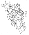
- FIG. 1 shows a versatile moveable and adjustable MRI magnet assembly in accordance with the present invention.
- FIGs. 2 and 3 are simplified drawings, partially in cross section illustrating the adjustability of the magnet assembly shown in FIG. 1 and in which the patient is differently positioned.
- FIG. 4 illustrates a larger magnet assembly with a simplified magnet adjustment mechanism.
- FIGs. 5 and 6 are simplified drawings, partially in cross section, illustrating the magnetic field inclination adjustment possible with the arrangements of FIG. 4 or FIG. 1.
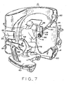
- FIG. 7 illustrates surgeon positioning and viewing of the patient for interventional procedure of the magnet assembly of FIGs. 1-6.
- FIG. 8 is a drawing partially in block diagram form and partially in pictorial form to illustrate the interconnection of the various elements of FIGs. 1-7.
- FIG. 9 is a block diagram illustrating a drive assembly utilized in the magnet positioning adjustments of FIGs. 1-8.
- FIG. 10 is a partial view of a magnet pole face illustrating the shimming arrangement for adjusting magnetic field homogeneity for changing magnetic field positions.
-
- Referring first to FIGs. 1-3, a
portable magnet assembly 10 includes abase 2 supported on wheels 4 driven by direct current electric motors indicated generally as 6. Housing 11 onbase 2 includes the power source such as rechargeable batteries shown generally within thedotted areas 12 of FIGs 2 and 3. - A pair of spaced apart
permanent magnets imaging volume 21 therebetween and establish a strong unified magnetic field in the imaging volume. A magnetic flux path betweenmagnets members flux path member 24 all of which are ferromagnetic material to complete the magnetic path between the magnets. A pair of gear drive assemblies orrotatable couplings magnetic positioning member 29.Rotatable coupling 26interconnects base 2 andmagnetic positioning member 29 whilerotatable coupling 28 interconnects the magnetic positioning member and magneticflux path member 24.Rotatable coupling 26 provides movement ofmagnetic positioning member 29 in the direction indicated by arrows 48 (see FIG. 2) whilerotatable coupling 28 provides rotation ofarms magnets arrows 50. The combined adjustability made possible throughrotatable couplings magnets head 46 of apatient 44 on a horizontal patient support 40 (see FIG. 2) which support may be a Trandelinberg mobile table which is moveable alongfloor 3 onmobile table wheels 43. - A patient may be examined while in alternate patient support such as
wheelchair 42. The driving assemblies orrotatable couplings rechargeable batteries 12 and controlled byhealthcare provider 36 which may be a technician, physician, or a surgeon operating controls shown generally as 34 to positionmagnet assembly 10 andpermanent magnets patient 44 whether on a horizontal support or in a wheelchair. A visual display orindicator 38 assists healthcare giver 36 to properly positionpermanent magnets floor 3, or over a greater range, including any selected position therebetween. - A magnetic shimming assembly comprising a plurality of magnetic members is carried in trays or drawers shown generally as 30 and 32 for movement along with their respective
permanent magnets drawer assemblies imaging volume 21, see United States Patent 5,389,909 entitled "Open Architecture Magnetic Resonance Imaging Passively Shimmed Superconducting Magnet Assembly", assigned to the same Assignee as the present invention. - However, it may be necessary to fine tune or reshim the magnetic field homogeneity of
imaging volume 21 for each of the preset positions of the magnetic field. This may be accomplished rapidly and accurately through use of the shimming arrangement shown in FIG. 10. - Referring to FIG. 10, direct current shim members such as 104 are positioned over or embedded in the
face 105 of one or both ofmagnets adjacent imaging volume 21.Shim members 104 includewindings 106 surrounding an iron laminate pin orcylinder 108 which could alternatively utilize a hexagonal or other polygonal cross-section such as thehexagon cross-section 110 ofshim member 112 to enable a greater density or closer packing of the shim members on theface 105. A dense packing is not shown in FIG. 10 but may be desirable for increased magnetic field homogeneity.Windings 106 are each connected to a variable directcurrent voltage source 116 via bifilar twisted leads 120 to control the superconducting current flow through the bifilar windings and to vary the flow for each preset position of the magnetic field. Computer 100 (see FIG. 8) may be programmed to provide the desired bifilar current flow for each of the shim coils at each of the preset positions of the magnetic field. The bifilar wound leads cancel undesired magnetic fields and forces that current flow though the leads might otherwise introduce and which could disturb the homogeneity of the magnetic field inimaging volume 21 betweenmagnets - Although not shown in FIG. 10, the ends of all of the
shim coils 106 would be connected to a direct current voltage source such as 116 controlled bycomputer 100 to provide the proper current for each preset or new position of the magnetic field. Depending on magnet configuration multiple coils at scattered locations could be connected to the same voltage source with the shimming current flow there through controlled bycomputer 100 varying the resistance in series with the voltage source. The computer controlled shimming could provide an automatic second fine tuning of magnetic field homogeneity after a patient was positioned betweenmagnets - FIG. 4 shows a larger non-portable
magnet assembly 10 without wheels 4 but with a simplified magnetic adjustment drive. Referring to FIGs. 4-6,base 2 is secured to, or positioned directly on,floor 3 such thatpatient 44 is moved betweenpermanent magnets tiltable seat 45.Non-ferromagnetic coupling gears gear teeth 58 onbase 2 and which also provide part of the magnetic return path betweenmagnets Permanent magnets control 64 onlever arms 66 as shown in simplified form in FIG. 5 or may be rotated by a motor driven gear drive shown generally as 59.Magnet assembly 10 thus can be rotated as indicated byarrow 68 aroundpatient 44 who may be positioned within imaging volume in the central region betweenpermanent magnets arrow 21 and raised or lowered by adjustment ofpatient support 40.Dotted lines magnets region 21, whilearrow 76 illustrates movement or adjustment of the magnetic field inclination indicated by arrow 17 (see FIG. 4) from the vertical to a position approximately 45 degrees to vertical to improve imaging of a particular area ofpatient 44. - FIG. 7 illustrates the access by a physician or
surgeon 36 topatient 44 onpatient support 40.Patient support 40 extends between the magnets to theimaging region 21 such thatpatient 44 being imaged is directly accessible to the physician orsurgeon 36 for interventional procedures. Such interventional procedures may include surgery, the positioning of surgical devices or sensors within the body such as in a vein or artery, and the implantation of medical devices withinpatient 44. Such procedures are facilitated by providing the surgeon with one or more video displays formatted and integrated by the MRI system as described in more detail below regarding FIG. 8.Visual display 38 can be a conventional display from the MRI imaging system whilevisual display 39, could be, for example, a three-dimensional blood vessel reconstruction provided by the MRI computer. That is, the surgeon can be provided with real time magnetic resonance imaging to facilitate and enable internal procedures in which direct visual observation by the surgeon is inadequate. - As further shown in FIG. 7,
surgeon 36 is seated onadjustable seat 78 onmoveable platform 80 of surgeon'sstation 82 which also includes a surgeon'scontrol panel 84,indicators 86 and controls such as 88 to enable the surgeon to position and adjustpermanent magnets patient 44.Visual display 39 may be adjustably positioned by adjustment of articulatedboom members adjustable joints 92 and 94.Control panel 96 onvisual display 39 enablessurgeon 36 to select the particular display desired from the MRI computer 100 (shown in FIG. 8). - Referring next to FIG. 8. FIG. 8 is a block diagram, partially in pictorial form which better illustrates the electrical interconnection of the components shown in FIGs. 1-7.
Magnet assembly 10 is connected tocomputer 100 with its associateddisplay 102.Computer 100 also generates the desired display atmagnet assembly 10, which if mobile will include wheels 4. These displays includevisual display 38 which may be the same or essentially the same as that shown bydisplay 102 atcomputer 100.Computer 100 also providesvisual display 39 with 3-dimensional blood vessel reconstruction images or other images as selected bycontrol 96 associated with the visual display.Display 39 shows a simplified sketch of the type of display which may be selected. In addition, a further optional display may include a head mounteddisplay 47 which may be worn bysurgeon 36 through use ofresilient band 43 in the same manner as goggles or eyeglasses, or positioned over the surgeon's eyeglasses This enablessurgeon 36 to avoid having to look up or away at a display such as 39 during interventional procedures onpatient 44. - FIG. 9 is a block diagram showing one form of a rotatable coupling or gear drive assembly such as 26, 28 and 59. Direct
current motor 104 is controlled by positioningcontrol 34 and connectedgear train 106 and drivinggear 108 to the driven member which may be part ofrotatable coupling 26 atbase 2, or part ofrotatable coupling 28 at the end ofarms rotatable coupling 59 which directly rotatesmagnets - It is thus to be seen that the present invention provides a flexible, adjustable magnet assembly for MRI imaging and interventional procedures providing mobility, adjustability, positioning and
magnetic field 17 rotational capabilities forpermanent magnets imaging volume 21 ofmagnet assembly 10. This enableshealthcare worker 16 to positionpatient 44 in a sitting prone or inclined position while at the same time positioning and orientingmagnets resultant magnet field 17 inimaging volume 21 at the desired inclination or orientation to enhance both the imaging of the patient and the accessibility of the patient to the surgeon for interventional procedures. A 45 degree orientation may be desirable, for example, for the imaging of knees, while a thirty degree field orientation may be desirable for an MRI guided biopsy of the spine of a prone patient. Magnetic field orientations which are intermediate the vertical and horizontal of the main axis of the human body provide better access to the human body for medical interventional procedures. - Orienting
magnetic field inclination 17 transverse tohuman body 44 but parallel to the plane offloor 3 allows for the structural supports maintaining the gap between the magnet halves to be arranged at different positions. In general, the positions of the structural supports will be selected to give the maximum open space in the vertical direction, however, selection of these positions is determined by the need to position human body orpatient 44 for the selected medical procedure. The flexibility possible withadjustable magnet assembly 10 facilities imaging of people that cannot maintain a lying position, increases patient support possibilities including typical weight bearing positions for medical evaluation. A vertical access configuration allows patient entry from one side of the system with comparable access for theclinician 36 from the other side (as shown in FIGs. 4 and 7) for direct manipulation ofpatient 44. Different applications are optimized by the transportability and adjustability of thesame magnet assembly 10 to the position most appropriate for the imaging of selected application with the shimming system optimizing the quality of the image for the selected position.
Claims (26)
- An open architecture magnet assembly (10) with selectively adjustable magnetic field orientation for interventional magnetic resonance imaging comprising:a base (2), a pair of magnets (14,16) with respective spaced apart permanent magnet pole faces supported on said base providing a magnetic field and imaging volume (21) in the space between said magnets (14,16);at least one member (24) extending outside said imaging volume to provide a magnetic flux return path for said magnets (14,16);said magnets (14,16) being selectively rotatable about at least one axis which is/are substantially parallel to said base to control the orientation and position of said magnetic field relative to said base to enable optimization of the imaging of a selected region of said patient in said imaging volume; the magnet assembly comprising:means (104) to automatically adjust the magnetic field homogeneity within said imaging volume at a plurality of selected orientations and positions of said magnetic field;said means to adjust said magnetic field homogeneity including a plurality of shimming coils (106) distributed on at least one of said magnets adjacent to said imaging volume, each coil (106) surrounding a respective magnetic core, with automatic current flow provided through the shimming coils at each said selected position and orientation of said magnetic field.
- The magnet assembly of claim 1 wherein said magnets (14,16) are selectively rotatable about a plurality of axes which are substantially parallel to said base, such that said orientation of said magnetic field is adjustable for at least approximately ninety degrees.
- The magnet assembly of claim 2 wherein said approximately ninety degrees extends from approximately the vertical to the horizontal relative to said base.
- The magnet assembly of claim 2 comprising a computer (100) controlling the current for each of said shimming coils (106) with predetermined current flows for preset positions of said magnets.
- The magnet assembly of claim 4 wherein said shimming coils are arranged to receive current through respective bifilar twisted lead pairs.
- The magnet assembly of claim 5 wherein said magnetic cores consist of laminated iron.
- The magnet assembly of claim 6 wherein said laminated cores have a polygonal cross-section.
- The magnet assembly of claim 2 wherein said at least one member (24) consists of ferromagnetic material.
- The magnet assembly of claim 3 wherein said magnets are adjustable about said base to optimize the accessibility of the physician to a patient (44) to be positioned in said imaging volume.
- The magnet assembly of claim 9 comprising patient support means (40) to position said patient (44) in a position selected from the group of positions consisting of seated and lying.
- The magnet assembly of claim 10 wherein the seated position is adjustable and includes a seat including a support portion the angle of which may be adjusted relative to said base.
- The magnet assembly of claim 11 wherein said magnets (14,16) are generally cylindrical in shape with an axial length significantly less than the circumference thereof.
- The magnet assembly of claim 1 wherein said magnets are selectively moveable in two directions.
- The magnet assembly of claim 13 wherein said magnets are connected to said base through at least two selectively rotatable couplings (26, 28).
- The magnet assembly of claim 14 wherein the first of said at least two couplings is secured to said base, and is connected to the second of said at least two couplings through a rigid connecting member, enabling rotations of said magnets (14,16) over approximately ninety degrees about two axes parallel to said base.
- The magnet assembly of claim 15 where each of said couplings is a motor driven gear coupling.
- The magnet assembly of claim 16 wherein said base (3) is moveable for positioning about a patient (44).
- The magnet assembly of claim 17 including wheels (4) on said base and an electric drive for selectively positioning said magnet assembly.
- The magnet assembly of claim 18 including a rechargeable battery mounted on said base and direct current motors positioning said base and for driving said gear couplings.
- The magnet assembly of claim 19 including controls for each of the motors of said magnet assembly.
- The magnet assembly of claim 20 wherein the space between said magnets is selected to enable said magnets to surround a patient on a support selected from a seated position support and a substantially prone position support.
- The magnet assembly of claim 1 wherein said magnet assembly includes at least two motor driven gear assemblies to position said permanent magnets and adjust said magnetic field orientation.
- The magnet assembly (10) of claim 1 including a visual magnetic resonance imager display (38) located proximate to said magnets (14,16) assembly to enable a health care worker to observe said display while engaging in an interventional procedure on a patient (44) positioned between said magnets (14,16).
- The magnet assembly of claim 23 wherein said visual display (39) is adjustably secured to said magnet assembly.
- The magnet assembly of claim 1 comprising a visual magnet resonance imager display (47) which is configured to be worn on the head of a physician for movement therewith to observe said display (38) while engaging in an interventional procedure on a patient (44) positioned between said magnets (14,16).
- The magnet assembly according to any of claims 23-25 further including a computer (100) to provide reconstructed three-dimensional images to said magnetic resonance imager display (38) and to control the current flow through said magnetic shim coils at preselected orientations of said magnetic field.
Applications Claiming Priority (2)
| Application Number | Priority Date | Filing Date | Title |
|---|---|---|---|
| US09/002,465 US6011396A (en) | 1998-01-02 | 1998-01-02 | Adjustable interventional magnetic resonance imaging magnet |
| US2465 | 1998-01-02 |
Publications (3)
| Publication Number | Publication Date |
|---|---|
| EP0927889A2 EP0927889A2 (en) | 1999-07-07 |
| EP0927889A3 EP0927889A3 (en) | 2001-04-18 |
| EP0927889B1 true EP0927889B1 (en) | 2005-12-28 |
Family
ID=21700897
Family Applications (1)
| Application Number | Title | Priority Date | Filing Date |
|---|---|---|---|
| EP98310426A Expired - Lifetime EP0927889B1 (en) | 1998-01-02 | 1998-12-18 | Adjustable interventional magnetic resonance imaging magnet |
Country Status (4)
| Country | Link |
|---|---|
| US (1) | US6011396A (en) |
| EP (1) | EP0927889B1 (en) |
| JP (1) | JP4165949B2 (en) |
| DE (1) | DE69832951T2 (en) |
Cited By (1)
| Publication number | Priority date | Publication date | Assignee | Title |
|---|---|---|---|---|
| US8126245B2 (en) | 2006-06-06 | 2012-02-28 | Esaote, S.P.A. | Apparatus for magnetic resonance imaging of patients with limbs, particularly lower limbs, under natural stress |
Families Citing this family (65)
| Publication number | Priority date | Publication date | Assignee | Title |
|---|---|---|---|---|
| US6023165A (en) * | 1992-09-28 | 2000-02-08 | Fonar Corporation | Nuclear magnetic resonance apparatus and methods of use and facilities for incorporating the same |
| US6411187B1 (en) | 1997-07-23 | 2002-06-25 | Odin Medical Technologies, Ltd. | Adjustable hybrid magnetic apparatus |
| WO1999015914A1 (en) | 1997-09-25 | 1999-04-01 | Odin Technologies Ltd. | Magnetic apparatus for mri |
| US7127802B1 (en) | 1997-11-21 | 2006-10-31 | Fonar Corporation | Method of fabricating a composite plate |
| JP3110011B2 (en) * | 1998-01-28 | 2000-11-20 | ジーイー横河メディカルシステム株式会社 | MRI apparatus and mobile table |
| JP3034841B2 (en) * | 1998-06-05 | 2000-04-17 | ジーイー横河メディカルシステム株式会社 | MRI coil, cradle and MRI device |
| JP3040748B2 (en) * | 1998-06-15 | 2000-05-15 | ジーイー横河メディカルシステム株式会社 | Vertical magnet device and MRI device for MRI |
| IT1305971B1 (en) | 1998-08-31 | 2001-05-21 | Esaote Spa | MACHINE FOR THE DETECTION OF IMAGES IN MAGNETIC-NUCLEAR RESONANCE OF THE TYPE DEDICATED TO THE DETECTION OF IMAGES OF LIMITED |
| IT1304768B1 (en) * | 1998-10-05 | 2001-03-29 | Esaote Spa | TABLE FOR PATIENT HOLDER OR SIMILAR, AND MACHINE, IN PARTICULAR MACHINE FOR DETECTION OF IMAGES IN NUCLEAR MAGNETIC RESONANCE IN |
| AU1582400A (en) * | 1998-12-08 | 2000-06-26 | Odin Medical Technologies Ltd | A device and a system for moving and positioning an open magnetic resonance imaging probe |
| US6591127B1 (en) * | 1999-03-15 | 2003-07-08 | General Electric Company | Integrated multi-modality imaging system and method |
| DE19923947A1 (en) * | 1999-05-25 | 2000-12-07 | Siemens Ag | Magnetic resonance tomography device |
| DE60023822T2 (en) * | 1999-06-14 | 2006-07-27 | Koninklijke Philips Electronics N.V. | DEVICE FOR MAGNETIC RESONANCE IMAGING EQUIPPED WITH CORROSIVE CONNECTING LINES FOR ELECTRICAL EQUIPMENT |
| US6317619B1 (en) * | 1999-07-29 | 2001-11-13 | U.S. Philips Corporation | Apparatus, methods, and devices for magnetic resonance imaging controlled by the position of a moveable RF coil |
| DE19959720B4 (en) * | 1999-12-10 | 2005-02-24 | Siemens Ag | Method for operating a magnetic resonance tomography device |
| DE10114013B4 (en) * | 2001-03-22 | 2005-06-23 | Siemens Ag | magnetic resonance system |
| US6504461B2 (en) * | 2001-03-26 | 2003-01-07 | General Electric Company | Open magnet with recessed field shaping coils |
| US6934574B1 (en) | 2001-06-21 | 2005-08-23 | Fonar Corporation | MRI scanner and method for modular patient handling |
| US6944492B1 (en) * | 2001-10-01 | 2005-09-13 | Fonar Corporation | Patient bed support for an open MRI system |
| US7906966B1 (en) | 2001-10-05 | 2011-03-15 | Fonar Corporation | Quadrature foot coil antenna for magnetic resonance imaging |
| US7701209B1 (en) | 2001-10-05 | 2010-04-20 | Fonar Corporation | Coils for horizontal field magnetic resonance imaging |
| JP3701616B2 (en) * | 2002-03-06 | 2005-10-05 | ジーイー・メディカル・システムズ・グローバル・テクノロジー・カンパニー・エルエルシー | Magnetic resonance imaging device |
| US7123008B1 (en) | 2002-04-19 | 2006-10-17 | Fonar Corporation | Positional magnetic resonance imaging |
| US8036730B1 (en) | 2002-04-19 | 2011-10-11 | Fonar Corporation | Temporal magnetic resonance imaging |
| WO2003094727A1 (en) * | 2002-05-13 | 2003-11-20 | Hitachi Medical Corporation | Magnetic resonance imaging system |
| DE10224192A1 (en) * | 2002-05-31 | 2003-12-18 | Fraunhofer Ges Forschung | Imaging NMR method and NMR device |
| US6984982B2 (en) * | 2002-07-29 | 2006-01-10 | Ge Medical Systems Global Technology Company Llc | Method and system for shimming an MRI magnet assembly |
| JP2006507095A (en) * | 2002-11-25 | 2006-03-02 | フォーナー・コーポレイション | Method, apparatus and facility for MRI dual scanning |
| US7102353B1 (en) | 2002-11-29 | 2006-09-05 | Fonar Corporation | Magnetic resonance imaging apparatus having moving magnets |
| US6954070B2 (en) * | 2003-01-06 | 2005-10-11 | Brk Wireless Company, Inc. | NMR imaging system with conical permanent magnet |
| US8064984B2 (en) * | 2003-03-18 | 2011-11-22 | Esaote S.P.A. | Magnetic resonance imaging apparatus |
| CN100504432C (en) * | 2003-05-23 | 2009-06-24 | 西门子(中国)有限公司 | Magnetostatic field regulating method in magnetic resonance equipment and magnetostatic field generating apparatus thereof |
| EP1495718B1 (en) * | 2003-07-11 | 2006-06-14 | Esaote S.p.A. | Apparatus for magnetic resonance imaging |
| US7030612B1 (en) | 2004-01-13 | 2006-04-18 | Fonar Corporation | Body rest for magnetic resonance imaging |
| US8195273B2 (en) | 2004-02-02 | 2012-06-05 | Esaote S.P.A. | Magnetic resonance imaging apparatus |
| US7378846B1 (en) | 2004-06-29 | 2008-05-27 | Fonar Corporation | Magnetic resonance imaging method and apparatus for scanning a child |
| US8401615B1 (en) | 2004-11-12 | 2013-03-19 | Fonar Corporation | Planar coil flexion fixture for magnetic resonance imaging and use thereof |
| WO2007038626A2 (en) * | 2005-09-28 | 2007-04-05 | President And Fellows Of Harvard College | Hyperpolarized solid materials with long spin relaxation times for use as imaging agents in magnetic resonance imaging |
| WO2007037380A1 (en) * | 2005-09-30 | 2007-04-05 | Hitachi Metals, Ltd. | Magnetic field control method and magnetic field generation device |
| US20080284429A1 (en) * | 2005-12-10 | 2008-11-20 | The President And Fellows Of Harvard College | Situ Hyperpolarization of Imaging Agents |
| JP2009523172A (en) * | 2006-01-11 | 2009-06-18 | プレジデント・アンド・フエローズ・オブ・ハーバード・カレツジ | Ex vivo hyperpolarization of contrast agents |
| JP5003681B2 (en) * | 2006-07-13 | 2012-08-15 | 日立金属株式会社 | Magnetic field control method and magnetic field generator |
| US8401612B1 (en) | 2006-09-11 | 2013-03-19 | Fonar Corporation | Magnetic resonance imaging system and method for detecting chiari malformations |
| EP1906195B1 (en) * | 2006-09-29 | 2008-12-24 | Esaote S.p.A. | MRI apparatus and MRI method using such apparatus |
| US9386939B1 (en) | 2007-05-10 | 2016-07-12 | Fonar Corporation | Magnetic resonance imaging of the spine to detect scoliosis |
| US8073524B2 (en) * | 2007-11-08 | 2011-12-06 | Imris Inc. | Control of magnetic field homogeneity in movable MRI scanning system |
| DE102008009673A1 (en) * | 2008-02-18 | 2009-08-20 | Siemens Aktiengesellschaft | Magnetic resonance system for use in magnet resonance tomography during medical examination of heart and liver of patient, has magnetic unit and patient bed, where magnetic unit is supported over multi-axle robot |
| EP2300841A4 (en) * | 2008-06-20 | 2017-08-30 | The University Of Queensland | Mri apparatus and method with moving field component |
| JP2011525389A (en) | 2008-06-24 | 2011-09-22 | アルバータ ヘルス サービシズ | Magnet assembly and method for determining a magnetic field for an imaging volume |
| TWM350429U (en) * | 2008-09-04 | 2009-02-11 | Earth Chain Entpr Co Ltd | Permanent magnet electric control type indexing device |
| US20100092390A1 (en) * | 2008-10-09 | 2010-04-15 | President And Fellows Of Harvard College | Methods for Making Particles Having Long Spin-Lattice Relaxation Times |
| KR101152537B1 (en) | 2010-10-12 | 2012-06-01 | 가톨릭대학교 산학협력단 | Magnetic resonance imaging system for dental clinic |
| WO2013122984A1 (en) * | 2012-02-13 | 2013-08-22 | The Childrens Hospital Of Philadelphia | Magnetic field apparatus for creating uniform magnetic field for vascular magnetic intervention |
| US11141080B1 (en) | 2013-03-13 | 2021-10-12 | Fonar Corporation | Cervical vertebra angle measurement |
| DE102013205213A1 (en) * | 2013-03-25 | 2014-10-09 | Siemens Aktiengesellschaft | Magnetic resonance device for receiving a limb of a patient |
| CA3043063A1 (en) | 2014-09-05 | 2016-03-10 | Hyperfine Research, Inc. | Low field magnetic resonance imaging methods and apparatus |
| DE202015104743U1 (en) * | 2015-08-18 | 2015-09-15 | Aspect Imaging Ltd. | Systems for inserting a MRI hyperpolarization of a patient with a weak field |
| US10627464B2 (en) | 2016-11-22 | 2020-04-21 | Hyperfine Research, Inc. | Low-field magnetic resonance imaging methods and apparatus |
| US10539637B2 (en) | 2016-11-22 | 2020-01-21 | Hyperfine Research, Inc. | Portable magnetic resonance imaging methods and apparatus |
| DE102017205485A1 (en) * | 2017-03-31 | 2018-10-04 | Bruker Biospin Gmbh | Permanent magnet arrangement for MR apparatus with axially and laterally displaceable, rotatably mounted ring assemblies |
| EP3827746A1 (en) * | 2019-11-27 | 2021-06-02 | Siemens Healthcare GmbH | Workflow for a dedicated magnetic resonance imaging system |
| US11675034B2 (en) * | 2020-05-04 | 2023-06-13 | Siemens Healthcare Gmbh | Magnetic resonance scanner and magnetic resonance imaging system |
| DE102020113242B4 (en) | 2020-05-15 | 2023-07-13 | Otto-Von-Guericke-Universität Magdeburg | medical system |
| CN116368394A (en) * | 2020-09-08 | 2023-06-30 | 海珀菲纳运营有限公司 | System and method for providing operating power to a Magnetic Resonance Imaging (MRI) system |
| CN113476070B (en) * | 2021-07-28 | 2022-04-05 | 北京锐视康科技发展有限公司 | Special PET check out test set of brain |
Family Cites Families (13)
| Publication number | Priority date | Publication date | Assignee | Title |
|---|---|---|---|---|
| US4673882A (en) * | 1984-03-06 | 1987-06-16 | Buford J Philip | Magnetic system for nuclear magnetic resonance diagnostic device |
| JPS62117541A (en) * | 1985-11-18 | 1987-05-29 | 株式会社東芝 | Magnetic resonance imaging apparatus |
| JPS63286142A (en) * | 1987-05-19 | 1988-11-22 | Toshiba Corp | Magnetic resonance imaging apparatus |
| JPH0217038A (en) * | 1988-07-06 | 1990-01-22 | Toshiba Corp | Magnetic resonance imaging apparatus |
| US4985678A (en) * | 1988-10-14 | 1991-01-15 | Picker International, Inc. | Horizontal field iron core magnetic resonance scanner |
| US5184074A (en) * | 1991-02-04 | 1993-02-02 | The Regents Of The University Of California | Real-time mr imaging inside gantry room |
| US5153546A (en) * | 1991-06-03 | 1992-10-06 | General Electric Company | Open MRI magnet |
| JP3742662B2 (en) * | 1992-08-05 | 2006-02-08 | ゼネラル・エレクトリック・カンパニイ | Magnet suitable for open magnetic resonance imaging |
| IL106779A0 (en) * | 1992-09-11 | 1993-12-08 | Magna Lab Inc | Permanent magnetic structure |
| US5490509A (en) * | 1993-03-18 | 1996-02-13 | The Regents Of The University Of California | Method and apparatus for MRI using selectively shaped image volume of homogeneous NMR polarizing field |
| US5423315A (en) * | 1993-11-22 | 1995-06-13 | Picker International, Inc. | Magnetic resonance imaging system with thin cylindrical uniform field volume and moving subjects |
| US5446434A (en) * | 1994-07-27 | 1995-08-29 | General Electric Company | Magnet having pole faces with trapezoidal-shaped shims |
| JPH0994234A (en) * | 1995-09-29 | 1997-04-08 | Olympus Optical Co Ltd | Mri apparatus |
-
1998
- 1998-01-02 US US09/002,465 patent/US6011396A/en not_active Expired - Lifetime
- 1998-12-18 DE DE69832951T patent/DE69832951T2/en not_active Expired - Lifetime
- 1998-12-18 EP EP98310426A patent/EP0927889B1/en not_active Expired - Lifetime
- 1998-12-28 JP JP37320898A patent/JP4165949B2/en not_active Expired - Fee Related
Cited By (1)
| Publication number | Priority date | Publication date | Assignee | Title |
|---|---|---|---|---|
| US8126245B2 (en) | 2006-06-06 | 2012-02-28 | Esaote, S.P.A. | Apparatus for magnetic resonance imaging of patients with limbs, particularly lower limbs, under natural stress |
Also Published As
| Publication number | Publication date |
|---|---|
| EP0927889A2 (en) | 1999-07-07 |
| JP2000201902A (en) | 2000-07-25 |
| JP4165949B2 (en) | 2008-10-15 |
| US6011396A (en) | 2000-01-04 |
| DE69832951D1 (en) | 2006-02-02 |
| EP0927889A3 (en) | 2001-04-18 |
| DE69832951T2 (en) | 2006-09-21 |
Similar Documents
| Publication | Publication Date | Title |
|---|---|---|
| EP0927889B1 (en) | Adjustable interventional magnetic resonance imaging magnet | |
| US6507192B1 (en) | Nuclear magnetic resonance apparatus and methods of use and facilities for incorporating the same | |
| US6437571B1 (en) | MRI apparatus | |
| US6208145B1 (en) | MRI apparatus | |
| Hinks et al. | MR systems for image‐guided therapy | |
| US8055326B1 (en) | Coils for horizontal field magnetic resonance imaging | |
| US6335623B1 (en) | MRI apparatus | |
| KR101650591B1 (en) | Mri compatible robot with calibration phantom and phantom | |
| US20020123681A1 (en) | Device and a system for moving and positioning an open magnetic resonance imaging probe | |
| US5647361A (en) | Magnetic resonance imaging method and apparatus for guiding invasive therapy | |
| US7196519B2 (en) | Stand-up vertical field MRI apparatus | |
| EP0943929A2 (en) | Magnetic resonance apparatus | |
| US20160051187A1 (en) | Magnetic resonance imaging | |
| US7680525B1 (en) | Method for lateral motion magnetic resonance imaging | |
| US7102353B1 (en) | Magnetic resonance imaging apparatus having moving magnets | |
| US7127802B1 (en) | Method of fabricating a composite plate | |
| US10791957B1 (en) | Magnetic resonance imaging | |
| US11852703B2 (en) | Magnetic resonance imaging device with a concave-shaped field generation unit | |
| JPH10295665A (en) | Magnetic resonance imaging device | |
| EP1689286B1 (en) | Stand-up vertical field mri apparatus |
Legal Events
| Date | Code | Title | Description |
|---|---|---|---|
| PUAI | Public reference made under article 153(3) epc to a published international application that has entered the european phase |
Free format text: ORIGINAL CODE: 0009012 |
|
| AK | Designated contracting states |
Kind code of ref document: A2 Designated state(s): DE GB NL |
|
| AX | Request for extension of the european patent |
Free format text: AL;LT;LV;MK;RO;SI |
|
| RIN1 | Information on inventor provided before grant (corrected) |
Inventor name: INOUE, YUJI Inventor name: HAYAKAWA, KAZUHIKO Inventor name: WANG, WANXIAN Inventor name: HOSHINO, KAZUYA Inventor name: COLLICK, BRUCE DAVID Inventor name: ECKELS, PHILLIP WILLIAM |
|
| PUAL | Search report despatched |
Free format text: ORIGINAL CODE: 0009013 |
|
| AK | Designated contracting states |
Kind code of ref document: A3 Designated state(s): AT BE CH CY DE DK ES FI FR GB GR IE IT LI LU MC NL PT SE |
|
| AX | Request for extension of the european patent |
Free format text: AL;LT;LV;MK;RO;SI |
|
| RIC1 | Information provided on ipc code assigned before grant |
Free format text: 7G 01R 33/38 A, 7G 01R 33/3875 B, 7A 61B 5/055 B |
|
| 17P | Request for examination filed |
Effective date: 20011018 |
|
| AKX | Designation fees paid |
Free format text: DE GB NL |
|
| 17Q | First examination report despatched |
Effective date: 20021220 |
|
| GRAP | Despatch of communication of intention to grant a patent |
Free format text: ORIGINAL CODE: EPIDOSNIGR1 |
|
| GRAS | Grant fee paid |
Free format text: ORIGINAL CODE: EPIDOSNIGR3 |
|
| GRAA | (expected) grant |
Free format text: ORIGINAL CODE: 0009210 |
|
| AK | Designated contracting states |
Kind code of ref document: B1 Designated state(s): DE GB NL |
|
| REG | Reference to a national code |
Ref country code: GB Ref legal event code: FG4D |
|
| REF | Corresponds to: |
Ref document number: 69832951 Country of ref document: DE Date of ref document: 20060202 Kind code of ref document: P |
|
| PLBE | No opposition filed within time limit |
Free format text: ORIGINAL CODE: 0009261 |
|
| STAA | Information on the status of an ep patent application or granted ep patent |
Free format text: STATUS: NO OPPOSITION FILED WITHIN TIME LIMIT |
|
| 26N | No opposition filed |
Effective date: 20060929 |
|
| PGFP | Annual fee paid to national office [announced via postgrant information from national office to epo] |
Ref country code: NL Payment date: 20071223 Year of fee payment: 10 |
|
| NLV4 | Nl: lapsed or anulled due to non-payment of the annual fee |
Effective date: 20090701 |
|
| PG25 | Lapsed in a contracting state [announced via postgrant information from national office to epo] |
Ref country code: NL Free format text: LAPSE BECAUSE OF NON-PAYMENT OF DUE FEES Effective date: 20090701 |
|
| PGFP | Annual fee paid to national office [announced via postgrant information from national office to epo] |
Ref country code: GB Payment date: 20101229 Year of fee payment: 13 |
|
| PGFP | Annual fee paid to national office [announced via postgrant information from national office to epo] |
Ref country code: DE Payment date: 20101229 Year of fee payment: 13 |
|
| GBPC | Gb: european patent ceased through non-payment of renewal fee |
Effective date: 20111218 |
|
| REG | Reference to a national code |
Ref country code: DE Ref legal event code: R119 Ref document number: 69832951 Country of ref document: DE Effective date: 20120703 |
|
| PG25 | Lapsed in a contracting state [announced via postgrant information from national office to epo] |
Ref country code: DE Free format text: LAPSE BECAUSE OF NON-PAYMENT OF DUE FEES Effective date: 20120703 Ref country code: GB Free format text: LAPSE BECAUSE OF NON-PAYMENT OF DUE FEES Effective date: 20111218 |