EP0921590A2 - Antenna for communicating with low earth orbit satellite - Google Patents
Antenna for communicating with low earth orbit satellite Download PDFInfo
- Publication number
- EP0921590A2 EP0921590A2 EP98309924A EP98309924A EP0921590A2 EP 0921590 A2 EP0921590 A2 EP 0921590A2 EP 98309924 A EP98309924 A EP 98309924A EP 98309924 A EP98309924 A EP 98309924A EP 0921590 A2 EP0921590 A2 EP 0921590A2
- Authority
- EP
- European Patent Office
- Prior art keywords
- antenna
- reflector
- satellite
- elevation
- earth orbit
- Prior art date
- Legal status (The legal status is an assumption and is not a legal conclusion. Google has not performed a legal analysis and makes no representation as to the accuracy of the status listed.)
- Withdrawn
Links
Images


Classifications
-
- H—ELECTRICITY
- H01—ELECTRIC ELEMENTS
- H01Q—ANTENNAS, i.e. RADIO AERIALS
- H01Q19/00—Combinations of primary active antenna elements and units with secondary devices, e.g. with quasi-optical devices, for giving the antenna a desired directional characteristic
- H01Q19/10—Combinations of primary active antenna elements and units with secondary devices, e.g. with quasi-optical devices, for giving the antenna a desired directional characteristic using reflecting surfaces
- H01Q19/12—Combinations of primary active antenna elements and units with secondary devices, e.g. with quasi-optical devices, for giving the antenna a desired directional characteristic using reflecting surfaces wherein the surfaces are concave
- H01Q19/13—Combinations of primary active antenna elements and units with secondary devices, e.g. with quasi-optical devices, for giving the antenna a desired directional characteristic using reflecting surfaces wherein the surfaces are concave the primary radiating source being a single radiating element, e.g. a dipole, a slot, a waveguide termination
- H01Q19/132—Horn reflector antennas; Off-set feeding
-
- H—ELECTRICITY
- H01—ELECTRIC ELEMENTS
- H01Q—ANTENNAS, i.e. RADIO AERIALS
- H01Q3/00—Arrangements for changing or varying the orientation or the shape of the directional pattern of the waves radiated from an antenna or antenna system
- H01Q3/12—Arrangements for changing or varying the orientation or the shape of the directional pattern of the waves radiated from an antenna or antenna system using mechanical relative movement between primary active elements and secondary devices of antennas or antenna systems
- H01Q3/16—Arrangements for changing or varying the orientation or the shape of the directional pattern of the waves radiated from an antenna or antenna system using mechanical relative movement between primary active elements and secondary devices of antennas or antenna systems for varying relative position of primary active element and a reflecting device
- H01Q3/20—Arrangements for changing or varying the orientation or the shape of the directional pattern of the waves radiated from an antenna or antenna system using mechanical relative movement between primary active elements and secondary devices of antennas or antenna systems for varying relative position of primary active element and a reflecting device wherein the primary active element is fixed and the reflecting device is movable
Definitions
- the present invention relates to an antenna for communicating with a low earth orbit satellite, particularly relates to an antenna for communicating with a low earth orbit satellite used for an earth station in a satellite communication system in which plural low earth orbit (LEO) satellites revolve around the earth for automatically tracking each satellite.
- LEO low earth orbit
- an antenna for tracking a satellite plural techniques are widely known as the antenna of an earth station for a geostationary satellite and a mobile satellite.
- a monopulse tracking method of continuously detecting whether an antenna tracks a satellite in the center of a beam or not and controlling so that a direction of a radiation pattern of an antenna is always equal to the direction of a satellite a step tracking method of shifting an antenna at a fixed interval of time by degrees and adjusting it in a bearing in which a receiving level is maximum and a program tracking method of changing the bearing of an antenna based upon the estimated information of a satellite orbit are known.
- an AZ-EL mount in which the azimuth and the elevation of the mobile antenna are shifted and a XY mount which the mobile antenna is shifted in a direction perpendicular to a satellite orbital direction are widely known.
- the AZ-EL mount is currently the most adopted method, one axis (the azimuth axis) is arranged perpendicularly to the ground and the other axis (the elevation axis) is arranged horizontally.
- the x-axis horizontal with the ground is perpendicular to the y-axis and the y-axis is turned together with the x-axis.
- the XY mount is suitable for tracking a LEO satellite which moves near the zenith at high speed, however, as both axes are located in high positions from the ground, the XY mount has a mechanical defect.
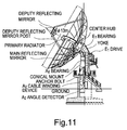
- Fig. 11 shows the constitution of a conventional type antenna of an earth station for tracking a satellite.
- Fig. 11 shows an example of a large-sized antenna of an earth station for tracking a satellite and the main reflector is Cassegrainian antenna 13 m in diameter.
- the antenna tracks a satellite using a driving mechanism according to the AZ-EL mount, and both the azimuth axis and the elevation axis are driven by a jackscrew driving mechanism.
- the driving mechanism is allowed to continuously drive only within a range of ⁇ 10° in the direction of the azimuth axis and a limited driving method that when an antenna is required to be directed at a larger angle in another direction, a set screw is loosened and the antenna is turned slowly is adopted.
- continuous driving between 0° and 90° is enabled.
- a primary feed is attached to the main reflector and is integrally driven with the main reflector.
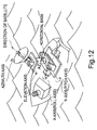
- Fig. 12 shows another conventional type antenna of an earth station for tracking a satellite and a small-sized antenna of an earth station for tracking a satellite in which miniaturization and lightening are realized though an aperture antenna is used as the above large-sized antenna is known.
- Fig. 12 shows a parabolic antenna used for a ship earth station according to International Maritime Satellite Organization (INMARSAT) standard A, and a cross dipole and a reflector board are located in the focus of a reflector with a paraboloid of revolution as a primary feed.
- the reflector and the radiator are integrated.
- the above parabolic antenna is driven using four-axes mounting obtained by combining the above AZ-EL mount and XY mount.
- the antenna to be turned is heavy, a driving system is also large-sized, high-speed tracking is difficult and the area of a radome for housing the antenna is also increased.
- the size of the whole antenna is required to be as small-sized as possible and as light as possible, and miniaturization and lightening are a large problem.
- a radio frequency (RF) sending/receiving section including a feeding system such as a low noise amplifier and a high-frequency power amplifier is required to be mounted near the primary feed so as to stably feed to the primary feed during turning.
- a feeding system such as a low noise amplifier and a high-frequency power amplifier
- the weight of the antenna is also increased by the weight of the RF sending/receiving section.
- the RF sending/receiving section is separated from the reflector and fixed to maintain stable connection independent of displacement by turning of the feeding section, a feeder cable is required to be flexible, a rotary joint and others are required and there is a problem that an antenna for satellite communication is complicated and high-priced.
- An object of the present invention is to provide an antenna for communicating with a low earth orbit satellite used for a small-sized earth station for communicating with plural LEO satellites, which is small-sized and light and can track a LEO satellite at high speed.
- the present invention provides an antenna for use at an earth station for communicating with a low earth orbit satellite, wherein said antenna comprises an offset aperture antenna for mechanically tracking said low earth orbit satellite.
- An antenna for communicating with a low earth orbit satellite is based upon an antenna for communicating with a low earth orbit satellite used on the side of the ground in a satellite communication system using low earth orbit satellite and mechanically tracks the above low earth orbit satellite using an offset aperture antenna.
- the above antenna may mechanically track by fixing a primary feed of the aperture antenna and turning only the reflector of the antenna based upon an azimuth and an elevation axis in a direction of a low earth orbit satellite.
- the present invention provides an antenna for use at an earth station for communicating with a low earth orbit satellite, said antenna comprising:
- a reflector having a predetermined offset paraboloid of revolution an AZ-EL mount connected to the reflector for turning the reflector based upon an azimuth axis and an elevation axis and tracking a low earth orbit satellite, a primary feed for radiating predetermined beams to the reflector, a feeding part for feeding to the primary feed and a radiator supporting part for supporting the primary feed so that the primary feed can be fixed independently of the reflecting feed may be provided.
- the value of the above offset is set so that antenna gain is maximum at a predetermined minimum operational elevation.
- the invention also extends to a method of communicating with a low earth orbit satellite, comprising the step of mechanically tracking the satellite with an offset aperture antenna.
- Fig. 1 is a block diagram showing the constitution of an antenna for communicating with a low earth orbit satellite equivalent to one embodiment of the present invention.
- an antenna for communicating with a low earth orbit satellite 100 is composed of a primary feed (horn) 1 for sending or receiving a signal in Ka band, an offset reflector 2 provided with a predetermined paraboloid of revolution, an AZ-EL mount 3 connected to the reflector 2 for turning an azimuth axis and an elevation axis and tracking a satellite, a feeding part 4 for feeding to the primary feed 1, a radiator supporting part 5 for fixing the primary feed 1, a, RF sending/receiving part 6 composed of a low noise amplifier and a high-frequency power amplifier and an antenna supporting part 7 for fixing the whole antenna.
- This antenna uses an offset parabolic antenna type reflecting antenna and the primary feed 1 is installed in the focal position of the paraboloid of revolution forming the reflector 2.
- the offset quantity of the offset parabolic antenna is selected so that antenna gain is maximum at the minimum operational elevation described later.
- the primary feed 1 has constitution mechanically independent of the reflector 2 with mobile structure, is attached to the radiator supporting part 5 and fixed.
- the, reflector 2 is constituted so that it is turned based upon the azimuth axis and the elevation axis by the AZ-EL mount 3.
- a signal and others from the primary feed 1 are fed to the RF sending/receiving part 6 via the feeding part 4.
- the AZ-EL mount 3, the radiator supporting part 5 and the RF sending/receiving part 6 are mounted on the antenna supporting part 7.
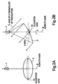
- Figs. 2A and 2B explain the tracking mechanism of this antenna and particularly shows the reflector 2 and the primary feed 1 respectively related to tracking.
- Fig. 2A shows the reflector 2 and the primary feed 1 viewed from a front
- a full line shows the position of the reflector 2 at the minimum operational elevation ⁇ MIN and a dotted line shows the position of the reflector 2 in case an elevation is approximately 90°.
- Fig. 2B shows the reflector 2 and the primary feed 1 respectively viewed from the side.
- an azimuth axis 9 is turned around a straight line connecting the center of the reflecting mirror 2 and the center of the primary feed 1 and the reflector 2 is turned 360° with the azimuth axis 9 in the center.
- a reference number 8 denotes the axis of a paraboloid of revolution.
- Figs. 3A and 3B explain an elevation axis and the elevation axis in these drawings means an axis which is in contact with a line perpendicular on a paraboloid of revolution to a radial straight line passing the parboloid of revolution of the offset reflector 2 from an intersection point (the center) of the axis 8 of the paraboloid of revolution and a paraboloid 9.
- An angle varies between the minimum operational elevation and 90° with the elevation axis in the center.
- the AZ-EL mount 3 drives the reflector 2 so that the reflector is turned around the azimuth axis 9 and the elevation axis 10 to track a satellite.
- the primary feed 1 is always fixed in the focal position of the paraboloid even if the reflector 2 is turned because the primary feed is fixed by the radiator support part 5.
- the satellite communication antenna turns the reflector 2 around the azimuth axis and can track a satellite in the omnibearing.
- the elevation showing directivity can be varied by turning the reflector 2 around the elevation axis and directivity in the direction of the zenith at which the elevation is 90° can be obtained.
- Fig. 4 is an imaginative drawing showing that multiple LEO satellites are arranged on plural orbital planes over the earth to cover the whole world.
- a satellite communication system for covering the whole world is provided by arranging plural LEO satellites over the earth so that any satellite can be seen in any place on the earth.
- a LEO satellite means a satellite on an elliptical orbit including a circular orbit at the altitude of approximately 1500 km over the ground or less and assuming that the orbital period of each satellite is 1000 km at altitude, each satellite turns over the earth in approximately one hour and forty-five minutes.
- the number of satellites to be arranged on the same orbital plane is 20 and ten orbital planes are required to cover the whole world. That is, the total number of required satellites is 200.
- the number of the required satellites is determined based upon the altitude and the minimum operational elevation of satellites and even if satellites are at the same altitude, the number of required satellites is 98 if the operational elevation is 20° and the number of required satellites is 45 if the operational elevation is 10°.
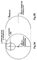
- Fig. 5 is a conceptual drawing showing a wide-band satellite communication system provided using LEO satellites.
- a low-speed channel of approximately 64 kbps using multi-beams in L band (1.5 to 1.6 GHz) is provided to a small-sized user such as a portable terminal and high speed data is provided to a large-sized user such as a ship, an airplane and a small-scale office using multiple spot beams in Ka band (generally called a quasi-millimeter wave band and 20 to 30 GHz) at a small-sized earth station.
- Ka band generally called a quasi-millimeter wave band and 20 to 30 GHz
- the present invention relates to the antenna for communicating with a low earth orbit satellite used at a small-sized earth station mainly for the latter user.
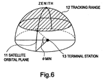
- Fig. 6 shows a satellite tracking range in case a LEO satellite provided with an orbital plane 11 is viewed from a small-sized earth station 13 on the ground.
- the minimum operational elevation ⁇ MIN is determined based upon relationship between the number of LEO satellites and altitude as described above and the satellite tracking range 12 is equivalent to an area shown by an oblique line, that is, the whole area in the omnibearing from the minimum operational elevation ⁇ MIN to the zenith.
- Fig. 7 shows relationship between propagation loss (A) composed of free-space loss based upon an elevation and loss due to attenuation by rainfall and the gain of an offset parabolic antenna (B).
- the minimum operational elevation ⁇ MIN is set to 40°. The quantity of an offset is adjusted so that antenna gain is maximum at the elevation and propagation loss is calculated using a sending frequency 30 GHz in Ka band.
- Fig. 7 shows that as a result, the total propagation loss is the largest at the minimum operational elevation 40° and as an elevation approaches the zenith, the total propagation loss decreases.
- the first embodiment of the present invention using an offset parabolic antenna is described above, however, the present invention is not limited to such an antenna provided with a single reflector.
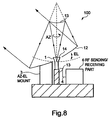
- an offset Cassegrainian antenna provided with plural reflectors shown in Fig. 8 may be also used.
- a reference number 12 denotes a main reflector having a paraboloid of revolution and as described above, a predetermined offset is applied to the main reflector so that the maximum antenna gain is obtained at the minimum operational elevation.
- a reference number 13 denotes a deputy reflector formed by a hyperboloid of revolution sharing the focus of a paraboloid of revolution as one focus. As the other focus of the hyperboloid of revolution is located in the area of the main reflector 12, a circular hole 14 for radiating beams from a primary feed 1 is provided to the main reflector 12.
- the other reference numbers are similar to those shown in Fig. 1, the description is omitted.
- the structure of the antenna is complicated, however, effect that loss in feeding is reduced, connection to a sending/receiving part is facilitated and blocking in a tracking range is prevented is produced because the primary feed 1 feeds from the rear surface of the main reflector 12.
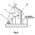
- an offset Cassegrainian antenna provided with plural reflecting mirrors shown in Fig. 9 is used.
- the offset Cassegrainian antenna provided with plural reflectors shown in Fig. 8 is also used, however, this embodiment is different from the second embodiment in that the position of a primary radiator 1 is outside the area of a main reflector 12.
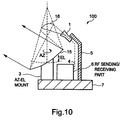
- an offset Gregorian antenna provided with plural reflectors shown in Fig. 10 may be also used.
- a predetermined offset is applied to a main reflector 15 having a paraboloid of revolution so that the maximum antenna gain is obtained at the minimum operational elevation.
- a deputy reflector 16 has an ellipsoid of revolution sharing the focus of the paraboloid of revolution. The center of the phase of a primary feed 1 is located in the other focus of the ellipsoid of revolution.
- loss in feeding is further reduced, the primary feed is fixed and the height of the whole antenna is further reduced, compared with the antenna in the first embodiment.
- the antenna for low earth orbit satellite communication produces the following effect:
- the best characteristics can be obtained at the minimum elevation at which propagation loss and attenuation by rainfall are the largest in a channel to a satellite by optimizing the side lobe characteristic of the antenna and cross-polarized electromagnetic radiation isolation because the offset parabolic antenna, the offset Cassegrainian antenna and others in which the maximum gain is obtained at the minimum operational elevation are used.
- the above effect is remarkable because a LEO satellite uses a millimeter wave band and attenuation by rainfall is large.
- the above antenna uses an offset parabolic antenna-type reflector and a primary feed is installed in the focal position of the paraboloid of revolution forming the reflector.
- the quantity of an offset of the offset parabolic antenna is selected so that antenna gain is maximum at the minimum operational elevation.
- the primary feed is mechanically independent of the mobile reflector and is attached and fixed to a radiator supporting part.
- the reflector is turned based upon an azimuth axis and an elevation axis according to AZ-EL mount.
Landscapes
- Aerials With Secondary Devices (AREA)
- Variable-Direction Aerials And Aerial Arrays (AREA)
Abstract
Description
- The present invention relates to an antenna for communicating with a low earth orbit satellite, particularly relates to an antenna for communicating with a low earth orbit satellite used for an earth station in a satellite communication system in which plural low earth orbit (LEO) satellites revolve around the earth for automatically tracking each satellite.
- Recently, a scheme that high-speed data at approximately a few Mbps to a few tens Mbps is provided to users all over the world using a high-frequency signal in Ka band (20 to 30 GHz) via plural LEO satellites is formed.
- In such a satellite communication system using plural LEO satellites, as each satellite goes off a visual field in relatively short time when viewed from a small-sized earth station, it is required to be tracked in a large range.
- Heretofore, for an antenna for tracking a satellite, plural techniques are widely known as the antenna of an earth station for a geostationary satellite and a mobile satellite.
- For example, for a method of tracking, a monopulse tracking method of continuously detecting whether an antenna tracks a satellite in the center of a beam or not and controlling so that a direction of a radiation pattern of an antenna is always equal to the direction of a satellite, a step tracking method of shifting an antenna at a fixed interval of time by degrees and adjusting it in a bearing in which a receiving level is maximum and a program tracking method of changing the bearing of an antenna based upon the estimated information of a satellite orbit are known.
- For a method of supporting a mobile antenna, an AZ-EL mount in which the azimuth and the elevation of the mobile antenna are shifted and a XY mount which the mobile antenna is shifted in a direction perpendicular to a satellite orbital direction are widely known. The AZ-EL mount is currently the most adopted method, one axis (the azimuth axis) is arranged perpendicularly to the ground and the other axis (the elevation axis) is arranged horizontally. In the XY mount, the x-axis horizontal with the ground is perpendicular to the y-axis and the y-axis is turned together with the x-axis. The XY mount is suitable for tracking a LEO satellite which moves near the zenith at high speed, however, as both axes are located in high positions from the ground, the XY mount has a mechanical defect.
- Next, referring to the drawings, the satellite tracking technique of an antenna of a conventional type concrete earth station for tracking a satellite will be described.
- Fig. 11 shows the constitution of a conventional type antenna of an earth station for tracking a satellite. Fig. 11 shows an example of a large-sized antenna of an earth station for tracking a satellite and the main reflector is
Cassegrainian antenna 13 m in diameter. The antenna tracks a satellite using a driving mechanism according to the AZ-EL mount, and both the azimuth axis and the elevation axis are driven by a jackscrew driving mechanism. To simplify structure, the driving mechanism is allowed to continuously drive only within a range of ±10° in the direction of the azimuth axis and a limited driving method that when an antenna is required to be directed at a larger angle in another direction, a set screw is loosened and the antenna is turned slowly is adopted. For the elevation axis, continuous driving between 0° and 90° is enabled. A primary feed is attached to the main reflector and is integrally driven with the main reflector. - Fig. 12 shows another conventional type antenna of an earth station for tracking a satellite and a small-sized antenna of an earth station for tracking a satellite in which miniaturization and lightening are realized though an aperture antenna is used as the above large-sized antenna is known.
- Fig. 12 shows a parabolic antenna used for a ship earth station according to International Maritime Satellite Organization (INMARSAT) standard A, and a cross dipole and a reflector board are located in the focus of a reflector with a paraboloid of revolution as a primary feed. In the antenna, the reflector and the radiator are integrated. To track a satellite, the above parabolic antenna is driven using four-axes mounting obtained by combining the above AZ-EL mount and XY mount.
- The above technique is described in "Guide to maritime satellite communication" written by Mr. Toshio Sato and published on Jul. 25, 1986 by Institute of Electronics and Communication Engineers of Japan.
- As described above, technique for tracking a satellite used for the conventional type antenna for satellite communication can be effectively applied to a case in which a tracking range is relatively small as a geostationary satellite, however, the above conventional type antenna is not suitable for the above antenna for tracking and communicating with a LEO satellite for the following reasons:
- That is, in the conventional type antenna for satellite communication, as the primary feed and the reflector are integrated and turn an antenna in tracking a satellite, the antenna to be turned is heavy, a driving system is also large-sized, high-speed tracking is difficult and the area of a radome for housing the antenna is also increased. In a satellite communication system using LEO satellites, considering that many small-sized earth stations are installed every home, the size of the whole antenna is required to be as small-sized as possible and as light as possible, and miniaturization and lightening are a large problem.
- Further, as the primary feed and the reflector are integrated and turn an antenna, a radio frequency (RF) sending/receiving section including a feeding system such as a low noise amplifier and a high-frequency power amplifier is required to be mounted near the primary feed so as to stably feed to the primary feed during turning. However, in this case, the weight of the antenna is also increased by the weight of the RF sending/receiving section.
- In this case, it is also conceivable that the RF sending/receiving section is separated from the reflector and fixed to maintain stable connection independent of displacement by turning of the feeding section, a feeder cable is required to be flexible, a rotary joint and others are required and there is a problem that an antenna for satellite communication is complicated and high-priced.
- An object of the present invention is to provide an antenna for communicating with a low earth orbit satellite used for a small-sized earth station for communicating with plural LEO satellites, which is small-sized and light and can track a LEO satellite at high speed.
- In a first aspect, the present invention provides an antenna for use at an earth station for communicating with a low earth orbit satellite, wherein said antenna comprises an offset aperture antenna for mechanically tracking said low earth orbit satellite.
- An antenna for communicating with a low earth orbit satellite according to the present invention is based upon an antenna for communicating with a low earth orbit satellite used on the side of the ground in a satellite communication system using low earth orbit satellite and mechanically tracks the above low earth orbit satellite using an offset aperture antenna. The above antenna may mechanically track by fixing a primary feed of the aperture antenna and turning only the reflector of the antenna based upon an azimuth and an elevation axis in a direction of a low earth orbit satellite.
- In a second aspect, the present invention provides an antenna for use at an earth station for communicating with a low earth orbit satellite, said antenna comprising:
- a reflector having a predetermined paraboloid of revolution;
- an AZ-EL mount connected to said reflector for tracking said low earth orbit satellite by turning said reflector about an azimuth axis and an elevation axis;
- a primary feed for feeding a beam on said reflector; and
- a radiator supporting part for supporting said primary feed so that said primary feed can be fixed independently of said reflector.
-
- By virtue of the above, a reflector having a predetermined offset paraboloid of revolution, an AZ-EL mount connected to the reflector for turning the reflector based upon an azimuth axis and an elevation axis and tracking a low earth orbit satellite, a primary feed for radiating predetermined beams to the reflector, a feeding part for feeding to the primary feed and a radiator supporting part for supporting the primary feed so that the primary feed can be fixed independently of the reflecting feed may be provided.
- The value of the above offset is set so that antenna gain is maximum at a predetermined minimum operational elevation.
- The invention also extends to a method of communicating with a low earth orbit satellite, comprising the step of mechanically tracking the satellite with an offset aperture antenna.
- Preferred features of the present invention will now be described, purely by way of example only, with reference to the accompanying drawings, in which:-
- Fig. 1 is a block diagram showing the constitution of an offset parabolic antenna for communicating with a low earth orbit satellite equivalent to a first embodiment of the present invention,
- Figs. 2A and 2B explain the tracking mechanism of the offset parabolic antenna shown in Fig. 1;
- Figs. 3A and 3B explain the definition of an elevation axis shown in Figs. 2A and 2B;
- Fig. 4 is a schematic drawing showing a LEO satellite;
- Fig. 5 shows as a satellite communication system using a LEO satellite;
- Fig. 6 shows a tracking range according to the present invention;
- Fig. 7 shows relationship among propagation loss between a pair of elevations, antenna gain and the whole propagation loss;
- Fig. 8 is a block diagram showing the constitution of an offset Cassegrainian antenna for communicating with a low earth orbit satellite equivalent to a second embodiment of the present invention;
- Fig. 9 is a block diagram showing the constitution of an offset Cassegrainian antenna for communicating with a low earth orbit satellite equivalent to a third embodiment of the present invention;
- Fig. 10 is a block diagram showing the constitution of an offset Gregorian type antenna for communicating with a low earth orbit satellite equivalent to the third embodiment of the present invention;
- Fig. 11 is an outside drawing showing the antenna tracking technique of a conventional type large-sized earth station; and
- Fig. 12 is a conceptual drawing showing the antenna tracking technique of a conventional type small-sized earth station.
-
- Next, referring to the drawings, a first embodiment of the present invention will be described in detail. Fig. 1 is a block diagram showing the constitution of an antenna for communicating with a low earth orbit satellite equivalent to one embodiment of the present invention.
- As shown in Fig. 1, an antenna for communicating with a low
earth orbit satellite 100 according to the present invention is composed of a primary feed (horn) 1 for sending or receiving a signal in Ka band, anoffset reflector 2 provided with a predetermined paraboloid of revolution, an AZ-EL mount 3 connected to thereflector 2 for turning an azimuth axis and an elevation axis and tracking a satellite, afeeding part 4 for feeding to theprimary feed 1, aradiator supporting part 5 for fixing theprimary feed 1, a, RF sending/receivingpart 6 composed of a low noise amplifier and a high-frequency power amplifier and anantenna supporting part 7 for fixing the whole antenna. - This antenna uses an offset parabolic antenna type reflecting antenna and the
primary feed 1 is installed in the focal position of the paraboloid of revolution forming thereflector 2. The offset quantity of the offset parabolic antenna is selected so that antenna gain is maximum at the minimum operational elevation described later. Theprimary feed 1 has constitution mechanically independent of thereflector 2 with mobile structure, is attached to theradiator supporting part 5 and fixed. - In the meantime, the,
reflector 2 is constituted so that it is turned based upon the azimuth axis and the elevation axis by the AZ-EL mount 3. A signal and others from theprimary feed 1 are fed to the RF sending/receivingpart 6 via thefeeding part 4. The AZ-EL mount 3, theradiator supporting part 5 and the RF sending/receivingpart 6 are mounted on theantenna supporting part 7. - Next, the operation of the
antenna 100 for communicating with a low earth orbit satellite shown in Fig. 1 will be described. - Figs. 2A and 2B explain the tracking mechanism of this antenna and particularly shows the
reflector 2 and theprimary feed 1 respectively related to tracking. Fig. 2A shows thereflector 2 and theprimary feed 1 viewed from a front, a full line shows the position of thereflector 2 at the minimum operational elevation MIN and a dotted line shows the position of thereflector 2 in case an elevation is approximately 90°. Fig. 2B shows thereflector 2 and theprimary feed 1 respectively viewed from the side. As also clear from these drawings, anazimuth axis 9 is turned around a straight line connecting the center of the reflectingmirror 2 and the center of theprimary feed 1 and thereflector 2 is turned 360° with theazimuth axis 9 in the center. Areference number 8 denotes the axis of a paraboloid of revolution. - In the meantime, Figs. 3A and 3B explain an elevation axis and the elevation axis in these drawings means an axis which is in contact with a line perpendicular on a paraboloid of revolution to a radial straight line passing the parboloid of revolution of the offset
reflector 2 from an intersection point (the center) of theaxis 8 of the paraboloid of revolution and aparaboloid 9. An angle varies between the minimum operational elevation and 90° with the elevation axis in the center. - The AZ-
EL mount 3 drives thereflector 2 so that the reflector is turned around theazimuth axis 9 and theelevation axis 10 to track a satellite. - The
primary feed 1 is always fixed in the focal position of the paraboloid even if thereflector 2 is turned because the primary feed is fixed by theradiator support part 5. - As described above, the satellite communication antenna according to the present invention turns the
reflector 2 around the azimuth axis and can track a satellite in the omnibearing. The elevation showing directivity can be varied by turning thereflector 2 around the elevation axis and directivity in the direction of the zenith at which the elevation is 90° can be obtained. - Next, a required range of tracking angles of the above antenna for communicating with a low earth orbit satellite will be described.
- Fig. 4 is an imaginative drawing showing that multiple LEO satellites are arranged on plural orbital planes over the earth to cover the whole world. As shown in Fig. 4, a satellite communication system for covering the whole world is provided by arranging plural LEO satellites over the earth so that any satellite can be seen in any place on the earth.
- A LEO satellite means a satellite on an elliptical orbit including a circular orbit at the altitude of approximately 1500 km over the ground or less and assuming that the orbital period of each satellite is 1000 km at altitude, each satellite turns over the earth in approximately one hour and forty-five minutes.
- Assuming that the altitude of a satellite is 765 km and the minimum operational elevation is 30°, the number of satellites to be arranged on the same orbital plane is 20 and ten orbital planes are required to cover the whole world. That is, the total number of required satellites is 200. The number of the required satellites is determined based upon the altitude and the minimum operational elevation of satellites and even if satellites are at the same altitude, the number of required satellites is 98 if the operational elevation is 20° and the number of required satellites is 45 if the operational elevation is 10°.
- Fig. 5 is a conceptual drawing showing a wide-band satellite communication system provided using LEO satellites. As shown in Fig. 5, in this system, a low-speed channel of approximately 64 kbps using multi-beams in L band (1.5 to 1.6 GHz) is provided to a small-sized user such as a portable terminal and high speed data is provided to a large-sized user such as a ship, an airplane and a small-scale office using multiple spot beams in Ka band (generally called a quasi-millimeter wave band and 20 to 30 GHz) at a small-sized earth station.
- The present invention relates to the antenna for communicating with a low earth orbit satellite used at a small-sized earth station mainly for the latter user.
- Fig. 6 shows a satellite tracking range in case a LEO satellite provided with an
orbital plane 11 is viewed from a small-sized earth station 13 on the ground. As shown in Fig. 6, the minimum operational elevation MIN is determined based upon relationship between the number of LEO satellites and altitude as described above and thesatellite tracking range 12 is equivalent to an area shown by an oblique line, that is, the whole area in the omnibearing from the minimum operational elevation MIN to the zenith. - Next, Fig. 7 shows relationship between propagation loss (A) composed of free-space loss based upon an elevation and loss due to attenuation by rainfall and the gain of an offset parabolic antenna (B). Fig. 7 also shows the sum of propagation loss (A) and the gain of the antenna (B), that is, the total propagation loss (
frequency 30 GHz in Ka band. - Fig. 7 shows that as a result, the total propagation loss is the largest at the minimum
operational elevation 40° and as an elevation approaches the zenith, the total propagation loss decreases. - The reason is that directional gain in the direction of the zenith low because it is off from the ideal condition of an offset parabolic reflector, however, in satellite communication in a microwave band, a millimeter wave band and others, antenna gain is required because a satellite is the farthest, free-space loss is increased, distance passing a rain-fall area is the longest and the quantity of attenuation by rainfall is the most when an elevation is small, while in the direction of the zenith, the above attenuation is the least.
- Therefore, problems can be really decreased by setting a suitable value as the minimum operational elevation even if an elevation is set to a direction of the zenith.
- The first embodiment of the present invention using an offset parabolic antenna is described above, however, the present invention is not limited to such an antenna provided with a single reflector.
- That is, for a second embodiment of the present invention, an offset Cassegrainian antenna provided with plural reflectors shown in Fig. 8 may be also used.
- As shown in Fig. 8, a
reference number 12 denotes a main reflector having a paraboloid of revolution and as described above, a predetermined offset is applied to the main reflector so that the maximum antenna gain is obtained at the minimum operational elevation. Areference number 13 denotes a deputy reflector formed by a hyperboloid of revolution sharing the focus of a paraboloid of revolution as one focus. As the other focus of the hyperboloid of revolution is located in the area of themain reflector 12, acircular hole 14 for radiating beams from aprimary feed 1 is provided to themain reflector 12. As the other reference numbers are similar to those shown in Fig. 1, the description is omitted. - In this embodiment, as the antenna provided with plural reflectors is adopted, the structure of the antenna is complicated, however, effect that loss in feeding is reduced, connection to a sending/receiving part is facilitated and blocking in a tracking range is prevented is produced because the
primary feed 1 feeds from the rear surface of themain reflector 12. - Further, for a third embodiment of the present invention, an offset Cassegrainian antenna provided with plural reflecting mirrors shown in Fig. 9 is used. In this embodiment, the offset Cassegrainian antenna provided with plural reflectors shown in Fig. 8 is also used, however, this embodiment is different from the second embodiment in that the position of a
primary radiator 1 is outside the area of amain reflector 12. - Further, for a fourth embodiment of the present invention, an offset Gregorian antenna provided with plural reflectors shown in Fig. 10 may be also used. In this embodiment, a predetermined offset is applied to a
main reflector 15 having a paraboloid of revolution so that the maximum antenna gain is obtained at the minimum operational elevation. Adeputy reflector 16 has an ellipsoid of revolution sharing the focus of the paraboloid of revolution. The center of the phase of aprimary feed 1 is located in the other focus of the ellipsoid of revolution. - According to the constitution described in the above second to fourth embodiments using the antenna provided with plural reflectors, loss in feeding is further reduced, the primary feed is fixed and the height of the whole antenna is further reduced, compared with the antenna in the first embodiment.
- As described above, the antenna for low earth orbit satellite communication according to the present invention produces the following effect:
- First, the best characteristics can be obtained at the minimum elevation at which propagation loss and attenuation by rainfall are the largest in a channel to a satellite by optimizing the side lobe characteristic of the antenna and cross-polarized electromagnetic radiation isolation because the offset parabolic antenna, the offset Cassegrainian antenna and others in which the maximum gain is obtained at the minimum operational elevation are used. Particularly, the above effect is remarkable because a LEO satellite uses a millimeter wave band and attenuation by rainfall is large.
- Second, as the primary feed is fixed, a flexible part is not required for a feeder and a waveguide, the structure is simplified and the reliability can be enhanced.
- Third, as a part driven for tracking a satellite is only the reflector, drive weight is small, tracking at high speed is enabled and the driving mechanism can be miniaturized and lightened.
- Each feature disclosed in this specification (which term includes the claims) and/or shown in the drawings may be incorporated in the invention independently of other disclosed and/or illustrated features.
- Statements in this specification of the "objects of the invention" relate to preferred embodiments of the invention, but not necessarily to all embodiments of the invention falling within the claims.
- The description of the invention with reference to the drawings is by way of example only.
- The text of the abstract filed herewith is repeated here as part of the specification.
- To provide an antenna for communicating with a low earth orbit (LEO) satellite which is small-sized and light and can track a LEO satellite at high speed at a small-sized earth station using a LEO satellite, the above antenna uses an offset parabolic antenna-type reflector and a primary feed is installed in the focal position of the paraboloid of revolution forming the reflector. The quantity of an offset of the offset parabolic antenna is selected so that antenna gain is maximum at the minimum operational elevation. The primary feed is mechanically independent of the mobile reflector and is attached and fixed to a radiator supporting part. The reflector is turned based upon an azimuth axis and an elevation axis according to AZ-EL mount.
Claims (13)
- An antenna for use at an earth station for communicating with a low earth orbit satellite, wherein said antenna comprises an offset aperture antenna for mechanically tracking said low earth orbit satellite.
- An antenna according to Claim 1, wherein:said aperture antenna comprises means for fixing a primary feed of said aperture antenna and means for turning only a reflector of said aperture antenna about an azimuth axis and an elevation axis in the direction of said low earth orbit satellite to track said satellite.
- An antenna for use at an earth station for communicating with a low earth orbit satellite said antenna comprising:a reflector having a predetermined paraboloid of revolution;an AZ-EL mount connected to said reflector for tracking said low earth orbit satellite by turning said reflector about an azimuth axis and an elevation axis;a primary feed for feeding a beam on said reflector; anda radiator supporting part for supporting said primary feed so that said primary feed can be fixed independently of said reflector.
- An antenna according to Claim 3, wherein:said offset is set so that antenna gain is a maximum at a predetermined minimum operational elevation.
- An antenna according to Claim 4, wherein:said predetermined minimum operational elevation is the limit of tracking in the direction of the elevation of said low earth orbit satellite; andsaid predetermined minimum operational elevation is determined based upon the number of satellites arranged on the same orbital plane as the altitude of said low earth orbit satellite.
- An antenna according to any of Claims 3 to 5, wherein: said antenna is an offset parabolic antenna.
- An antenna according to any of Claims 3 to 5, wherein: said antenna is an offset Cassegrainian antenna.
- An antenna according to any of Claims 3 to 5, wherein: said antenna is an offset Gregorian antenna.
- An antenna according to any of Claims 3 to 5, wherein:said azimuth axis is arranged to turn around a straight line connecting the centre of said reflector and the centre of said primary feed; andsaid elevation axis is arranged to come in contact with a line perpendicular on the paraboloid of revolution to a radial straight line passing the paraboloid of revolution of an offset reflector from an intersection of the axis of the paraboloid of revolution and a paraboloid.
- An antenna according to any of Claims 3 to 9, wherein:a range in which said low earth orbit satellite is tracked ranges from said minimum operational elevation to the zenith in the direction of an elevation and ranges from 0° to 360° in the direction of an azimuth.
- An antenna according to any of Claims 3 to 10, wherein:said antenna is adapted to send/receive a high-frequency signal either in a microwave band or in a millimetre wave band.
- A method of communicating with a low earth orbit satellite, comprising the step of mechanically tracking the satellite with an offset aperture antenna.
- A method according to Claim 12, wherein said step of mechanically tracking the satellite comprises fixing a primary feed of the antenna and turning only a reflector of the antenna about an azimuth axis and an elevation axis in the direction of the satellite.
Applications Claiming Priority (2)
| Application Number | Priority Date | Filing Date | Title |
|---|---|---|---|
| JP33406097 | 1997-12-04 | ||
| JP09334060A JP3109584B2 (en) | 1997-12-04 | 1997-12-04 | Antenna device for low orbit satellite communication |
Publications (2)
| Publication Number | Publication Date |
|---|---|
| EP0921590A2 true EP0921590A2 (en) | 1999-06-09 |
| EP0921590A3 EP0921590A3 (en) | 1999-09-15 |
Family
ID=18273065
Family Applications (1)
| Application Number | Title | Priority Date | Filing Date |
|---|---|---|---|
| EP98309924A Withdrawn EP0921590A3 (en) | 1997-12-04 | 1998-12-03 | Antenna for communicating with low earth orbit satellite |
Country Status (5)
| Country | Link |
|---|---|
| EP (1) | EP0921590A3 (en) |
| JP (1) | JP3109584B2 (en) |
| CN (1) | CN1219004A (en) |
| AU (1) | AU9520798A (en) |
| TW (1) | TW405279B (en) |
Cited By (2)
| Publication number | Priority date | Publication date | Assignee | Title |
|---|---|---|---|---|
| EP1408581A2 (en) * | 2002-10-08 | 2004-04-14 | EMS Technologies Canada, Limited | Steerable offset antenna with fixed feed source |
| US10283860B2 (en) | 2014-02-17 | 2019-05-07 | Nec Corporation | Antenna device and antenna device control method |
Families Citing this family (8)
| Publication number | Priority date | Publication date | Assignee | Title |
|---|---|---|---|---|
| WO2002071538A1 (en) * | 2001-03-02 | 2002-09-12 | Mitsubishi Denki Kabushiki Kaisha | Reflector antenna |
| AU2002354448A1 (en) * | 2001-12-10 | 2003-06-23 | Digital Wave Co., Ltd. | Insect tactile dipole antenna, directional antenna, and area control antenna |
| JP2006261994A (en) * | 2005-03-16 | 2006-09-28 | Toshiba Corp | Antenna device |
| EP2528159A3 (en) * | 2007-03-16 | 2013-02-13 | Mobile SAT Ltd. | A method for communicating through a satellite |
| JP5004846B2 (en) * | 2008-03-26 | 2012-08-22 | 三菱電機株式会社 | Beam scanning reflector antenna |
| EP2584650B1 (en) * | 2011-10-17 | 2017-05-24 | MacDonald, Dettwiler and Associates Corporation | Wide scan steerable antenna with no key-hole |
| CN111900551A (en) * | 2020-06-17 | 2020-11-06 | 深圳捷豹电波科技有限公司 | Millimeter wave parabolic antenna, control method thereof and computer readable storage medium |
| CN116404419A (en) * | 2023-06-07 | 2023-07-07 | 武汉能钠智能装备技术股份有限公司四川省成都市分公司 | Satellite signal broadband outdoor acquisition method and device |
Citations (4)
| Publication number | Priority date | Publication date | Assignee | Title |
|---|---|---|---|---|
| US4312002A (en) * | 1977-09-13 | 1982-01-19 | Marconi Company Limited | Combined radar and infrared scanning antenna |
| US4862185A (en) * | 1988-04-05 | 1989-08-29 | The Boeing Company | Variable wide angle conical scanning antenna |
| WO1990006004A1 (en) * | 1988-11-14 | 1990-05-31 | Crooks Michell Peacock Stewart (Qld) Pty. Limited | Offset parabolic reflector antenna |
| GB2226186A (en) * | 1988-11-15 | 1990-06-20 | Kokusai Denshin Denwa Co Ltd | An offset reflector antenna |
-
1997
- 1997-12-04 JP JP09334060A patent/JP3109584B2/en not_active Expired - Fee Related
-
1998
- 1998-12-02 TW TW87120120A patent/TW405279B/en not_active IP Right Cessation
- 1998-12-03 EP EP98309924A patent/EP0921590A3/en not_active Withdrawn
- 1998-12-03 AU AU95207/98A patent/AU9520798A/en not_active Abandoned
- 1998-12-04 CN CN 98125182 patent/CN1219004A/en active Pending
Patent Citations (4)
| Publication number | Priority date | Publication date | Assignee | Title |
|---|---|---|---|---|
| US4312002A (en) * | 1977-09-13 | 1982-01-19 | Marconi Company Limited | Combined radar and infrared scanning antenna |
| US4862185A (en) * | 1988-04-05 | 1989-08-29 | The Boeing Company | Variable wide angle conical scanning antenna |
| WO1990006004A1 (en) * | 1988-11-14 | 1990-05-31 | Crooks Michell Peacock Stewart (Qld) Pty. Limited | Offset parabolic reflector antenna |
| GB2226186A (en) * | 1988-11-15 | 1990-06-20 | Kokusai Denshin Denwa Co Ltd | An offset reflector antenna |
Cited By (3)
| Publication number | Priority date | Publication date | Assignee | Title |
|---|---|---|---|---|
| EP1408581A2 (en) * | 2002-10-08 | 2004-04-14 | EMS Technologies Canada, Limited | Steerable offset antenna with fixed feed source |
| EP1408581A3 (en) * | 2002-10-08 | 2004-05-26 | EMS Technologies Canada, Limited | Steerable offset antenna with fixed feed source |
| US10283860B2 (en) | 2014-02-17 | 2019-05-07 | Nec Corporation | Antenna device and antenna device control method |
Also Published As
| Publication number | Publication date |
|---|---|
| JPH11168322A (en) | 1999-06-22 |
| CN1219004A (en) | 1999-06-09 |
| JP3109584B2 (en) | 2000-11-20 |
| EP0921590A3 (en) | 1999-09-15 |
| AU9520798A (en) | 1999-06-24 |
| TW405279B (en) | 2000-09-11 |
Similar Documents
| Publication | Publication Date | Title |
|---|---|---|
| US6262689B1 (en) | Antenna for communicating with low earth orbit satellite | |
| US9281561B2 (en) | Multi-band antenna system for satellite communications | |
| US6043788A (en) | Low earth orbit earth station antenna | |
| US6281853B1 (en) | Terminal-antenna device for moving satellite constellation | |
| US8497810B2 (en) | Multi-band antenna system for satellite communications | |
| US6204822B1 (en) | Multibeam satellite communication antenna | |
| US20020167449A1 (en) | Low profile phased array antenna | |
| EP0597318B1 (en) | Multibeam antenna for receiving satellite | |
| EP0921590A2 (en) | Antenna for communicating with low earth orbit satellite | |
| US6747604B2 (en) | Steerable offset antenna with fixed feed source | |
| US6972730B2 (en) | Antenna system | |
| US6243047B1 (en) | Single mirror dual axis beam waveguide antenna system | |
| KR102284920B1 (en) | an Antenna System for receiving multiple satellite signals | |
| US11831346B2 (en) | Adaptable, reconfigurable mobile very small aperture (VSAT) satellite communication terminal using an electronically scanned array (ESA) | |
| US6172649B1 (en) | Antenna with high scanning capacity | |
| WO2023235538A2 (en) | Tracking antenna with stationary reflector | |
| JPH08204440A (en) | Beam power feeding type double reflection mirror antenna and its using method | |
| JPS6012804B2 (en) | Earth station antenna device | |
| JPH01277007A (en) | Antenna system | |
| JPS61220503A (en) | Antenna | |
| AU7242700A (en) | Multibeam satellite communication antenna | |
| JP2002111373A (en) | Sub-reflector mirror offset paraboloidal antenna | |
| JPH04250705A (en) | Multi-beam antenna |
Legal Events
| Date | Code | Title | Description |
|---|---|---|---|
| PUAI | Public reference made under article 153(3) epc to a published international application that has entered the european phase |
Free format text: ORIGINAL CODE: 0009012 |
|
| AK | Designated contracting states |
Kind code of ref document: A2 Designated state(s): GB SE |
|
| AX | Request for extension of the european patent |
Free format text: AL;LT;LV;MK;RO;SI |
|
| PUAL | Search report despatched |
Free format text: ORIGINAL CODE: 0009013 |
|
| AK | Designated contracting states |
Kind code of ref document: A3 Designated state(s): AT BE CH CY DE DK ES FI FR GB GR IE IT LI LU MC NL PT SE |
|
| AX | Request for extension of the european patent |
Free format text: AL;LT;LV;MK;RO;SI |
|
| 17P | Request for examination filed |
Effective date: 19990820 |
|
| AKX | Designation fees paid |
Free format text: GB SE |
|
| REG | Reference to a national code |
Ref country code: DE Ref legal event code: 8566 |
|
| 17Q | First examination report despatched |
Effective date: 20030731 |
|
| STAA | Information on the status of an ep patent application or granted ep patent |
Free format text: STATUS: THE APPLICATION IS DEEMED TO BE WITHDRAWN |
|
| 18D | Application deemed to be withdrawn |
Effective date: 20031211 |