EP0921094A2 - Aerial work platform with removably attachable support structure for auxiliary power plant - Google Patents
Aerial work platform with removably attachable support structure for auxiliary power plant Download PDFInfo
- Publication number
- EP0921094A2 EP0921094A2 EP98119731A EP98119731A EP0921094A2 EP 0921094 A2 EP0921094 A2 EP 0921094A2 EP 98119731 A EP98119731 A EP 98119731A EP 98119731 A EP98119731 A EP 98119731A EP 0921094 A2 EP0921094 A2 EP 0921094A2
- Authority
- EP
- European Patent Office
- Prior art keywords
- work platform
- aerial work
- support structure
- support frame
- battery pack
- Prior art date
- Legal status (The legal status is an assumption and is not a legal conclusion. Google has not performed a legal analysis and makes no representation as to the accuracy of the status listed.)
- Granted
Links
Images


Classifications
-
- B—PERFORMING OPERATIONS; TRANSPORTING
- B66—HOISTING; LIFTING; HAULING
- B66F—HOISTING, LIFTING, HAULING OR PUSHING, NOT OTHERWISE PROVIDED FOR, e.g. DEVICES WHICH APPLY A LIFTING OR PUSHING FORCE DIRECTLY TO THE SURFACE OF A LOAD
- B66F11/00—Lifting devices specially adapted for particular uses not otherwise provided for
- B66F11/04—Lifting devices specially adapted for particular uses not otherwise provided for for movable platforms or cabins, e.g. on vehicles, permitting workmen to place themselves in any desired position for carrying out required operations
- B66F11/044—Working platforms suspended from booms
Definitions
- the present invention relates to aerial work platforms; and more particularly, to an aerial work platform having a removably attachable support structure for auxiliary power plant.
- Aerial work platforms such as disclosed in U.S. Patent 5,584,356 to Goodrich include an electric motor for supplying motive power, and a battery pack for supplying power to the electric motor.
- the batteries When the charge on the battery pack decreases below an operational threshold level, the batteries must be recharged using known battery chargers. During this recharging period, the aerial work platform is unavailable for use.
- aerial work platforms need to be driven some distance to reach a work site.
- driving to the work site can drain the battery pack to such a level that recharging is required.
- One object of the present invention is to provide an aerial work platform which overcomes the problems and disadvantages discussed above.
- An object of the invention is to provide an aerial work platform which can operate for extended periods without an external source of electrical power.
- Another object of the present invention is to provide an aerial work platform having a removably attachable support structure for an auxiliary power plant.
- an aerial work platform comprising: a support frame; wheels rotatably attached to said support frame; an electric motor rotatably driving at least one of said wheels; a boom having a first end pivotably mounted to said support frame; a fluid motor raising and lower said boom with respect to said support frame; a work platform supported by a second end of said boom; a battery pack supplying power to said electric motor; and a first support structure for supporting an auxiliary power plant that supplements power supplied by said battery pack, said first support structure removably attaching to said support frame.
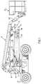
- Figs. 1 and 2 illustrate the aerial work platform according to the present invention in a retracted and extended state, respectively.
- the aerial work platform includes a superstructure support frame 1, having vertically extending plates 2 upon which counterweights, not shown, are adapted to be mounted.
- the support frame is mounted on a turntable 3 carried by a vehicle chassis 4.
- An articulated parallelogram boom assembly 5 is operatively connected between the support frame 1 and a riser 6 connected to the proximate end portion of telescopic boom assembly 7 having a work platform 8 mounted on the distal end thereof.
- the articulated parallelogram boom assembly 5 includes a lower boom assembly having pairs of parallel, laterally spaced compression and tension arms 9 and 10, respectively, extending between the support frame 1 and a floating frame 11.
- the compression and tension arms 9 and 10 are pivotally connected to the support frame as at 12 and 13, and to the floating frame as at 14 and 15.
- the articulated parallelogram boom assembly 5 also includes an upper boom assembly having pairs of parallel, laterally spaced compression and tension arms 16 and 17, respectively, extending between the riser 6 and the floating frame 11.
- the compression and tension arms 16 and 17 are pivotally connected to the riser as at 18 and 19, and to the floating frame 11, as at 20 and 15.
- An extensible hydraulic cylinder 21, positioned on the centerline of the machine, is pivotally connected as at 22 to and between the lower compression arms 9, and as at 23 to and between the upper compression arms 16; whereby, when the cylinder 21 is retracted, the parallelogram assembly 5 is in the folded position, as shown in FIG. 1, and is in the elevated position, as shown in FIG. 2, when the hydraulic cylinder 21 is extended.
- a boom lift cylinder 24 is similarly pivotally connected along the centerline of the machine, above the cylinder 21, between the riser 6, as at 25, and the telescopic boom assembly 7, as at 26.
- the remaining components on the telescopic boom assembly 7 include a master hydraulic cylinder 27 for controlling a slave cylinder 28 on the distal end of the telescopic boom assembly 7 for maintaining the work platform 8 in a horizontal position during the raising and lowering of the parallelogram assembly 5 and the luffing of the telescopic boom assembly 7 with boom lift cylinder 24.
- the cylinder 21 is nested between the pairs of arms 9, 10, 17, and 16; the boom lift cylinder 24 is nested between arms 16 above the cylinder 21; and the master hydraulic cylinder 27 as well as the cylinder inside the telescopic boom assembly 7, for extending and retracting the same, are positioned above the other cylinders on the centerline of the machine.
- Fig. 3 illustrates a top down view of the vehicle chassis 4 for the aerial work platform according to the present invention.
- a first tray 50 connected by hooks 52 in a cantilever fashion to the vehicle chassis 4, supports a battery pack 54.
- the battery pack 54 includes a plurality of batteries connected in series to produce a predetermined voltage. A portion of each member forming the hooks 52 bends away from the first tray 50 to form ears 56.
- Fig. 4 shows a perspective view of the first tray 50.
- the first tray 50 has a bottom 57 with side walls 58 extending therefrom.
- Each side wall 58 has a hook 52 fixed thereto. A portion of the member forming each hook 52 bends away from the side wall 58 to form an ear 56.
- the ears 56 facilitate hooking the first tray 50 on the vehicle chassis 4. For instance, cables can be hooked onto the ears 56, and the first tray 50 with the battery pack 54 thereon lifted by means of the cables to hook the first tray 50 on the vehicle chassis 4 by inserting hooks 52 into slots 53 in the side of chassis 4 (Fig. 1).
- a second tray 60 identical in structure to first tray 50, is connected by hooks 52 in a cantilever fashion to slots 53 in the opposite side of vehicle chassis 4.
- the second tray 60 supports an auxiliary power plant 64 which includes a voltage regulator 66 connected to a power plant 68. As shown, the voltage regulator 66 is connected to the battery pack 54.
- a motor controller 70 is also connected to the battery pack 54 and, in addition, is connected to an electric motor 72.
- the electric motor 72 drives the rear wheels of the aerial work platform.
- the battery pack 54 powers the hydraulic control system (not shown) of the aerial work platform.
- the motor controller 70 regulates the voltage output by the battery pack 54 in accordance with user input received via, for instance, a throttle, and supplies the regulated voltage to the electric motor 72. Because the first tray 50 is removably attachable to the vehicle chassis 4 via hooks 52, the battery pack 54 can be readily hooked and unhooked from the vehicle chassis 4. After hooking the first tray 50 on the vehicle chassis 4, the battery pack 54 is electrically connected to the motor controller 70 via, for instance, cables. The battery pack 54 can also be connected to the auxiliary power plant 64 via, for instance, cables, if such a power plant is provided for the aerial work platform. It should be understood that, according to the invention, the auxiliary power plant may be selectively provided for the aerial work platform.
- the power plant 68 in the auxiliary power plant may be any type of well-known power plant which generates electric power.
- the power plant 68 is a voltage generator driven by a gasoline or diesel powered combustion engine.
- the power plant 68 is a voltage generator driven by a propane engine.
- the power plant 68 is a Kubota ZB600 diesel engine driving an alternator and generator.
- the voltage generated by the power plant 68 is supplied to the voltage regulator 66.
- the voltage regulator 66 may be any well-known voltage regulator.
- the voltage regulator 66 monitors the voltage or charge on the battery pack 54, and when the charge on the battery pack 54 decreases below a predetermined threshold voltage, the voltage regulator 66 supplies the voltage generated by the power plant 68 to the battery pack 54. More specifically, the voltage regulator 66 controls the amount of current flowing to the battery pack 54 based on the difference between the charge on the battery pack 54 and the predetermined threshold voltage.
- the voltage supplied by the voltage regulator 66 includes fluctuations unwanted in a power supply for an electric motor. However, because the voltage output from the voltage regulator 66 charges the battery pack 54, as opposed to serving as a direct power supply for the electric motor 72, the battery pack 54 operates as a filter to remove such fluctuations.
- the auxiliary power plant 64 can be readily hooked and unhooked from the vehicle chassis 4.
- the voltage regulator 66 is electrically connected to the battery pack 54 via, for instance, cables.
- the second tray 60 with the auxiliary power plant 64 thereon can be hooked onto the vehicle chassis 4, and then placed in operation so as to maintain the battery pack 54 charged and operational.
- the auxiliary power plant 64 is also useful when the aerial work platform must be used for an extended period at a location where electric power is not available for recharging the battery pack 54.
- the second tray 60 is easily removed from the vehicle chassis 4, by unhooking the second tray 60 therefrom. Accordingly, the aerial work platform according to the present invention is extremely versatile.
- the battery pack 54 can easily be replaced or exchanged because the first tray 50 supporting the battery pack 54 is also removably attachable to the vehicle chassis 4.
Landscapes
- Engineering & Computer Science (AREA)
- Structural Engineering (AREA)
- Life Sciences & Earth Sciences (AREA)
- Geology (AREA)
- Mechanical Engineering (AREA)
- Forklifts And Lifting Vehicles (AREA)
- Harvesting Machines For Specific Crops (AREA)
Abstract
Description
- The present invention relates to aerial work platforms; and more particularly, to an aerial work platform having a removably attachable support structure for auxiliary power plant.
- Aerial work platforms such as disclosed in U.S. Patent 5,584,356 to Goodrich include an electric motor for supplying motive power, and a battery pack for supplying power to the electric motor. When the charge on the battery pack decreases below an operational threshold level, the batteries must be recharged using known battery chargers. During this recharging period, the aerial work platform is unavailable for use.
- Often, such aerial work platforms need to be driven some distance to reach a work site. Unfortunately, driving to the work site can drain the battery pack to such a level that recharging is required.
- One object of the present invention is to provide an aerial work platform which overcomes the problems and disadvantages discussed above.
- An object of the invention is to provide an aerial work platform which can operate for extended periods without an external source of electrical power.
- Another object of the present invention is to provide an aerial work platform having a removably attachable support structure for an auxiliary power plant.
- These and other objects are achieved by providing an aerial work platform, comprising: a support frame; wheels rotatably attached to said support frame; an electric motor rotatably driving at least one of said wheels; a boom having a first end pivotably mounted to said support frame; a fluid motor raising and lower said boom with respect to said support frame; a work platform supported by a second end of said boom; a battery pack supplying power to said electric motor; and a first support structure for supporting an auxiliary power plant that supplements power supplied by said battery pack, said first support structure removably attaching to said support frame.
- Further scope of applicability of the present invention will become apparent from the detailed description given hereinafter. However, it should be understood that the detailed description and specific examples, while indicating preferred embodiments of the invention, are given by way of illustration only, since various changes and modifications within the spirit and scope of the invention will become apparent to those skilled in the art from this detailed description.
- The present invention will become more fully understood from the detailed description given hereinbelow and the accompanying drawings which are given by way of illustration only, and thus are not limitative of the present invention, and wherein:
- Figs. 1 and 2 illustrate the aerial work platform according to the present invention in a retracted and extended state, respectively;
- Fig. 3 illustrates a top down view of the vehicle chassis for the aerial work platform according to the present invention; and
- Fig. 4 shows a perspective view of the first tray in the aerial work platform according to the present invention.
-
- Figs. 1 and 2 illustrate the aerial work platform according to the present invention in a retracted and extended state, respectively. The aerial work platform includes a superstructure support frame 1, having vertically extending
plates 2 upon which counterweights, not shown, are adapted to be mounted. The support frame is mounted on aturntable 3 carried by a vehicle chassis 4. An articulatedparallelogram boom assembly 5 is operatively connected between the support frame 1 and ariser 6 connected to the proximate end portion oftelescopic boom assembly 7 having a work platform 8 mounted on the distal end thereof. - The articulated
parallelogram boom assembly 5 includes a lower boom assembly having pairs of parallel, laterally spaced compression andtension arms tension arms parallelogram boom assembly 5 also includes an upper boom assembly having pairs of parallel, laterally spaced compression andtension arms riser 6 and the floating frame 11. The compression andtension arms hydraulic cylinder 21, positioned on the centerline of the machine, is pivotally connected as at 22 to and between thelower compression arms 9, and as at 23 to and between theupper compression arms 16; whereby, when thecylinder 21 is retracted, theparallelogram assembly 5 is in the folded position, as shown in FIG. 1, and is in the elevated position, as shown in FIG. 2, when thehydraulic cylinder 21 is extended. - A
boom lift cylinder 24 is similarly pivotally connected along the centerline of the machine, above thecylinder 21, between theriser 6, as at 25, and thetelescopic boom assembly 7, as at 26. The remaining components on thetelescopic boom assembly 7 include a masterhydraulic cylinder 27 for controlling aslave cylinder 28 on the distal end of thetelescopic boom assembly 7 for maintaining the work platform 8 in a horizontal position during the raising and lowering of theparallelogram assembly 5 and the luffing of thetelescopic boom assembly 7 withboom lift cylinder 24. In the folded or retracted position of theparallelogram assembly 5, thecylinder 21 is nested between the pairs ofarms boom lift cylinder 24 is nested betweenarms 16 above thecylinder 21; and the masterhydraulic cylinder 27 as well as the cylinder inside thetelescopic boom assembly 7, for extending and retracting the same, are positioned above the other cylinders on the centerline of the machine. - Fig. 3 illustrates a top down view of the vehicle chassis 4 for the aerial work platform according to the present invention. As shown in Fig. 3, a
first tray 50, connected byhooks 52 in a cantilever fashion to the vehicle chassis 4, supports abattery pack 54. Thebattery pack 54 includes a plurality of batteries connected in series to produce a predetermined voltage. A portion of each member forming thehooks 52 bends away from thefirst tray 50 to formears 56. - Fig. 4 shows a perspective view of the
first tray 50. As shown, thefirst tray 50 has abottom 57 with side walls 58 extending therefrom. Each side wall 58 has ahook 52 fixed thereto. A portion of the member forming eachhook 52 bends away from the side wall 58 to form anear 56. - The
ears 56 facilitate hooking thefirst tray 50 on the vehicle chassis 4. For instance, cables can be hooked onto theears 56, and thefirst tray 50 with thebattery pack 54 thereon lifted by means of the cables to hook thefirst tray 50 on the vehicle chassis 4 by insertinghooks 52 intoslots 53 in the side of chassis 4 (Fig. 1). - Similarly, a
second tray 60, identical in structure tofirst tray 50, is connected byhooks 52 in a cantilever fashion toslots 53 in the opposite side of vehicle chassis 4. Thesecond tray 60 supports anauxiliary power plant 64 which includes avoltage regulator 66 connected to apower plant 68. As shown, thevoltage regulator 66 is connected to thebattery pack 54. - A motor controller 70 is also connected to the
battery pack 54 and, in addition, is connected to anelectric motor 72. Theelectric motor 72 drives the rear wheels of the aerial work platform. Besides supplying power to theelectric motor 72, thebattery pack 54 powers the hydraulic control system (not shown) of the aerial work platform. - In operation, the motor controller 70 regulates the voltage output by the
battery pack 54 in accordance with user input received via, for instance, a throttle, and supplies the regulated voltage to theelectric motor 72. Because thefirst tray 50 is removably attachable to the vehicle chassis 4 viahooks 52, thebattery pack 54 can be readily hooked and unhooked from the vehicle chassis 4. After hooking thefirst tray 50 on the vehicle chassis 4, thebattery pack 54 is electrically connected to the motor controller 70 via, for instance, cables. Thebattery pack 54 can also be connected to theauxiliary power plant 64 via, for instance, cables, if such a power plant is provided for the aerial work platform. It should be understood that, according to the invention, the auxiliary power plant may be selectively provided for the aerial work platform. - The
power plant 68 in the auxiliary power plant may be any type of well-known power plant which generates electric power. For example, in one embodiment thepower plant 68 is a voltage generator driven by a gasoline or diesel powered combustion engine. As another example, thepower plant 68 is a voltage generator driven by a propane engine. In a preferred embodiment, thepower plant 68 is a Kubota ZB600 diesel engine driving an alternator and generator. Although the following details do not form part of the presently claimed invention, in order to reduce the size, noise, and heat characteristics in the above system using the Kubota diesel engine, certain modifications can be made such as mounting the alternator and generator to the engine, changing the exhaust silencing system, and remotely mounting the coolant system, water pump, drive system, and air cleaning system within thesecond tray 60. - The voltage generated by the
power plant 68 is supplied to thevoltage regulator 66. Thevoltage regulator 66 may be any well-known voltage regulator. Thevoltage regulator 66 monitors the voltage or charge on thebattery pack 54, and when the charge on thebattery pack 54 decreases below a predetermined threshold voltage, thevoltage regulator 66 supplies the voltage generated by thepower plant 68 to thebattery pack 54. More specifically, thevoltage regulator 66 controls the amount of current flowing to thebattery pack 54 based on the difference between the charge on thebattery pack 54 and the predetermined threshold voltage. Unlike the voltage output by thebattery pack 54, the voltage supplied by thevoltage regulator 66 includes fluctuations unwanted in a power supply for an electric motor. However, because the voltage output from thevoltage regulator 66 charges thebattery pack 54, as opposed to serving as a direct power supply for theelectric motor 72, thebattery pack 54 operates as a filter to remove such fluctuations. - As with the
first tray 50, because thesecond tray 60 is removably attachable to the vehicle chassis 4 viahooks 52, theauxiliary power plant 64 can be readily hooked and unhooked from the vehicle chassis 4. After hooking thesecond tray 60 on the vehicle chassis 4, thevoltage regulator 66 is electrically connected to thebattery pack 54 via, for instance, cables. - When lengthy aerial work platform operation is required, such as when driving an extended distance to a work site, the
second tray 60 with theauxiliary power plant 64 thereon can be hooked onto the vehicle chassis 4, and then placed in operation so as to maintain thebattery pack 54 charged and operational. Theauxiliary power plant 64 is also useful when the aerial work platform must be used for an extended period at a location where electric power is not available for recharging thebattery pack 54. However, in those environments which prohibit the use of, for example, internal combustion power plants, thesecond tray 60 is easily removed from the vehicle chassis 4, by unhooking thesecond tray 60 therefrom. Accordingly, the aerial work platform according to the present invention is extremely versatile. In a similar manner, thebattery pack 54 can easily be replaced or exchanged because thefirst tray 50 supporting thebattery pack 54 is also removably attachable to the vehicle chassis 4. - The invention being thus described, it will be obvious that the same may be varied in many ways. Such variations are not to be regarded as a departure from the spirit and scope of the invention, and all such modifications as would be obvious to one skilled in the art are intended to be included within the scope of the following claims.
Claims (8)
- An aerial work platform, comprising:a support frame (1, 4);wheels rotatably attached to said support frame (1, 4);an electric motor (72) rotatably driving at least one of said wheels;a boom (5) having a first end pivotably mounted to said support frame (1, 4)0;a fluid motor (21) raising and lower said boom (5) with respect to said support frame (1, 4);a work platform (8) supported by a second end of said boom (5);a battery pack (54) supplying power to said electric motor (72); anda first support structure (60) for supporting an auxiliary power plant that supplements power supplied by said battery pack (54), said first support structure (60) removably attaching to said support frame (1, 4).
- The aerial work platform of claim 1, wherein said battery pack (54) filters said electric power output by said auxiliary power plant.
- The aerial work platform of claim 1, wherein said first support structure (60) is a cantilever support structure which removably attaches to said support frame (1, 4) in a cantilevered manner.
- The aerial work platform of claim 3, wherein said first support structure (60) comprises:a tray (60); andhooks (52) attached to said tray (60).
- The aerial work platform of claim 4, wherein said first support structure (60) further comprises:a pair of projecting members (56) projecting from said tray (60).
- The aerial work platform of claim 1, further comprising:a second support structure (50) supporting said battery pack (54), said second support structure (50) removably attaching to said support frame (1, 4) so that said battery pack (54) removably attaches to said aerial work platform.
- The aerial work platform of claim 6, wherein said second support structure (50) is a cantilever support structure which removably attaches to said support frame (1, 4) in a cantilevered manner.
- The aerial work platform of claim 1, wherein said first support structure (60) is for supporting a combustion-based auxiliary power plant.
Applications Claiming Priority (2)
| Application Number | Priority Date | Filing Date | Title |
|---|---|---|---|
| US08/957,798 US6012544A (en) | 1997-10-24 | 1997-10-24 | Aerial work platform with removably attachable support structure for auxiliary power plant |
| US957798 | 1997-10-24 |
Publications (3)
| Publication Number | Publication Date |
|---|---|
| EP0921094A2 true EP0921094A2 (en) | 1999-06-09 |
| EP0921094A3 EP0921094A3 (en) | 2000-12-20 |
| EP0921094B1 EP0921094B1 (en) | 2005-03-30 |
Family
ID=25500154
Family Applications (1)
| Application Number | Title | Priority Date | Filing Date |
|---|---|---|---|
| EP98119731A Expired - Lifetime EP0921094B1 (en) | 1997-10-24 | 1998-10-20 | Aerial work platform with removably attachable support structure for auxiliary power plant |
Country Status (6)
| Country | Link |
|---|---|
| US (1) | US6012544A (en) |
| EP (1) | EP0921094B1 (en) |
| JP (1) | JPH11217194A (en) |
| AU (1) | AU751548B2 (en) |
| CA (1) | CA2251302C (en) |
| DE (1) | DE69829541D1 (en) |
Cited By (11)
| Publication number | Priority date | Publication date | Assignee | Title |
|---|---|---|---|---|
| EP1090874A1 (en) * | 1999-10-06 | 2001-04-11 | Atecs Mannesmann AG | Mobile crane |
| NL1020371C2 (en) * | 2002-04-11 | 2003-10-14 | Skf Ab | Electric powered forklift. |
| EP1557393A2 (en) * | 2004-01-23 | 2005-07-27 | CTE S.p.A. | Lifting vehicle with telescopic arm |
| ITBO20090469A1 (en) * | 2009-07-22 | 2011-01-23 | Hinowa S P A | AERIAL PLATFORM |
| ITUB20155900A1 (en) * | 2015-11-25 | 2017-05-25 | Magni Telescopic Handlers S R L | SELF PROPELLED AERIAL PLATFORM |
| FR3092101A1 (en) * | 2019-01-29 | 2020-07-31 | Haulotte Group | ELEVATOR PLATFORM SUITABLE FOR ALL TERRAIN OUTDOOR USE |
| WO2020157094A3 (en) * | 2019-01-29 | 2020-12-24 | Haulotte Group | Elevating nacelle suitable for indoor and all-terrain outdoor use |
| FR3102472A1 (en) * | 2019-10-25 | 2021-04-30 | Haulotte Group | LIFT PLATFORM WITH A LOCATION FOR A REMOVABLE GENERATOR |
| EP3055152B1 (en) | 2013-10-11 | 2021-05-05 | Hudson I.P. B.V. | Electric drive of mobile apparatus |
| WO2021178921A1 (en) * | 2020-03-06 | 2021-09-10 | Oshkosh Corporation | Lift device with split battery pack |
| WO2021178881A1 (en) * | 2020-03-06 | 2021-09-10 | Oshkosh Corporation | Battery monitoring system for a lift device |
Families Citing this family (11)
| Publication number | Priority date | Publication date | Assignee | Title |
|---|---|---|---|---|
| US6810993B2 (en) * | 2002-07-29 | 2004-11-02 | Terex-Telelect, Inc. | Articulated aerial device including an upper boom compensation unit |
| US20080251593A1 (en) * | 2007-04-12 | 2008-10-16 | Brandt Richard F | Natural or propane gas feed auxiliary electric generating system for boilers or furnaces |
| DE102010012469A1 (en) | 2010-03-24 | 2011-09-29 | Hermann Paus Maschinenfabrik Gmbh | Mobile working device in the form of an inclined lift |
| CN102351138A (en) * | 2011-09-22 | 2012-02-15 | 北京三兴汽车有限公司 | Simple vehicle-mounted lifting device |
| US11305972B1 (en) * | 2011-11-11 | 2022-04-19 | Vehcile Service Group, Llc | Vehicle lift with locally stored energy source |
| US8979467B1 (en) * | 2013-10-16 | 2015-03-17 | Jeffrey H. Bailey | Crane having a toolless removable battery and progressive function control |
| US9120651B1 (en) * | 2013-10-16 | 2015-09-01 | Jeffrey H. Bailey | Crane having a toolless removable battery and progressive function control |
| IT201600106155A1 (en) * | 2016-10-21 | 2018-04-21 | Magni Telescopic Handlers S R L | CONTROL PANEL FOR MACHINE OPERATOR |
| FR3113047B1 (en) | 2020-07-30 | 2022-10-21 | Haulotte Group | Removable device lockable in a dedicated location of a machine |
| EP4373779A1 (en) * | 2021-07-21 | 2024-05-29 | Haulotte Group | Self-propelling piece of lifting machinery having a main electrical power source and able to accommodate various interchangeable secondary electrical power sources |
| FR3125520B1 (en) * | 2021-07-21 | 2023-12-22 | Haulotte Group | Self-propelled lifting machine having a main source of electrical energy and capable of receiving different interchangeable secondary electrical energy sources |
Citations (4)
| Publication number | Priority date | Publication date | Assignee | Title |
|---|---|---|---|---|
| US4593779A (en) * | 1982-12-21 | 1986-06-10 | Still Gmbh | Combination internal combustion and electrical drive vehicles |
| US5251721A (en) * | 1992-04-21 | 1993-10-12 | Richard Ortenheim | Semi-hybrid electric automobile |
| US5441123A (en) * | 1993-04-01 | 1995-08-15 | Gnb Battery Technologies Inc. | Sealed lead-acid cell tray assembly and motive powered vehicle using such cell tray assembly |
| WO1998033672A2 (en) * | 1997-01-30 | 1998-08-06 | Jlg Industries, Inc. | Hybrid power system for a vehicle |
Family Cites Families (6)
| Publication number | Priority date | Publication date | Assignee | Title |
|---|---|---|---|---|
| US1734645A (en) * | 1928-04-16 | 1929-11-05 | Bruno A Polland | Battery-box holddown |
| US3667563A (en) * | 1969-11-21 | 1972-06-06 | Allis Chalmers Mfg Co | Supporting structure for platform defining fuel and battery compartment |
| JPS4930648B1 (en) * | 1969-12-12 | 1974-08-15 | ||
| DE2522844C3 (en) * | 1975-05-23 | 1979-01-11 | Bayerische Motoren Werke Ag, 8000 Muenchen | Electrically powered vehicles, in particular passenger cars |
| US4019604A (en) * | 1975-06-16 | 1977-04-26 | Fabtek, Inc. | Elevating platform apparatus |
| US5584356A (en) * | 1995-05-31 | 1996-12-17 | Kidde Industries, Inc. | Centerline double riser with single lift cylinder and link for a low profile self propelled aerial work platform |
-
1997
- 1997-10-24 US US08/957,798 patent/US6012544A/en not_active Expired - Lifetime
-
1998
- 1998-10-19 CA CA002251302A patent/CA2251302C/en not_active Expired - Lifetime
- 1998-10-20 EP EP98119731A patent/EP0921094B1/en not_active Expired - Lifetime
- 1998-10-20 DE DE69829541T patent/DE69829541D1/en not_active Expired - Lifetime
- 1998-10-22 AU AU89476/98A patent/AU751548B2/en not_active Expired
- 1998-10-23 JP JP10302123A patent/JPH11217194A/en active Pending
Patent Citations (4)
| Publication number | Priority date | Publication date | Assignee | Title |
|---|---|---|---|---|
| US4593779A (en) * | 1982-12-21 | 1986-06-10 | Still Gmbh | Combination internal combustion and electrical drive vehicles |
| US5251721A (en) * | 1992-04-21 | 1993-10-12 | Richard Ortenheim | Semi-hybrid electric automobile |
| US5441123A (en) * | 1993-04-01 | 1995-08-15 | Gnb Battery Technologies Inc. | Sealed lead-acid cell tray assembly and motive powered vehicle using such cell tray assembly |
| WO1998033672A2 (en) * | 1997-01-30 | 1998-08-06 | Jlg Industries, Inc. | Hybrid power system for a vehicle |
Non-Patent Citations (1)
| Title |
|---|
| SHIMIZU H ET AL: "A SERIES HYBRID CHERRY PICKER" EVS. INTERNATIONAL ELECTRIC VEHICLE SYMPOSIUM,JP,TOKYO, JEVA, vol. SYMP. 13, 13 October 1996 (1996-10-13), pages 24-29, XP000688940 * |
Cited By (26)
| Publication number | Priority date | Publication date | Assignee | Title |
|---|---|---|---|---|
| EP1090874A1 (en) * | 1999-10-06 | 2001-04-11 | Atecs Mannesmann AG | Mobile crane |
| NL1020371C2 (en) * | 2002-04-11 | 2003-10-14 | Skf Ab | Electric powered forklift. |
| WO2003086944A1 (en) * | 2002-04-11 | 2003-10-23 | Ab Skf | Electrically driven fork lift truck |
| EP1557393A2 (en) * | 2004-01-23 | 2005-07-27 | CTE S.p.A. | Lifting vehicle with telescopic arm |
| EP1557393A3 (en) * | 2004-01-23 | 2008-02-13 | CTE S.p.A. | Lifting vehicle with telescopic arm |
| ITBO20090469A1 (en) * | 2009-07-22 | 2011-01-23 | Hinowa S P A | AERIAL PLATFORM |
| EP3055152B1 (en) | 2013-10-11 | 2021-05-05 | Hudson I.P. B.V. | Electric drive of mobile apparatus |
| ITUB20155900A1 (en) * | 2015-11-25 | 2017-05-25 | Magni Telescopic Handlers S R L | SELF PROPELLED AERIAL PLATFORM |
| CN108290727A (en) * | 2015-11-25 | 2018-07-17 | 马格尼自动操作机有限公司 | self-propelled aerial platform |
| KR20180086236A (en) * | 2015-11-25 | 2018-07-30 | 마그니 텔레스코픽 핸들러스 에스.알.엘. | Self propelled aerial platform |
| JP2018535168A (en) * | 2015-11-25 | 2018-11-29 | マーニ テレスコピック ハンドラーズ エス.アール.エルMagni Telescopic Handlers S.R.L. | Self-propelled aerial platform |
| AU2016359090B2 (en) * | 2015-11-25 | 2019-07-18 | Zhejiang Dingli Machinery Co., Ltd. | A self-propelled aerial platform |
| WO2017089879A1 (en) * | 2015-11-25 | 2017-06-01 | Magni Telescopic Handlers S.R.L. | A self-propelled aerial platform |
| CN108290727B (en) * | 2015-11-25 | 2023-08-25 | 马格尼自动操作机有限公司 | self-propelled aerial platform |
| FR3092101A1 (en) * | 2019-01-29 | 2020-07-31 | Haulotte Group | ELEVATOR PLATFORM SUITABLE FOR ALL TERRAIN OUTDOOR USE |
| WO2020157094A3 (en) * | 2019-01-29 | 2020-12-24 | Haulotte Group | Elevating nacelle suitable for indoor and all-terrain outdoor use |
| EP4321472A3 (en) * | 2019-01-29 | 2024-03-06 | Haulotte Group | Aerial work platform with a location for a removable power generator |
| FR3102472A1 (en) * | 2019-10-25 | 2021-04-30 | Haulotte Group | LIFT PLATFORM WITH A LOCATION FOR A REMOVABLE GENERATOR |
| WO2021178921A1 (en) * | 2020-03-06 | 2021-09-10 | Oshkosh Corporation | Lift device with split battery pack |
| WO2021178867A1 (en) * | 2020-03-06 | 2021-09-10 | Oshkosh Corporation | Lift device with deployable operator station |
| WO2021178859A1 (en) * | 2020-03-06 | 2021-09-10 | Oshkosh Corporation | Lift device innovations |
| WO2021178881A1 (en) * | 2020-03-06 | 2021-09-10 | Oshkosh Corporation | Battery monitoring system for a lift device |
| US11230463B2 (en) | 2020-03-06 | 2022-01-25 | Oshkosh Corporation | Lift device with split battery pack |
| US11247885B2 (en) | 2020-03-06 | 2022-02-15 | Oshkosh Corporation | Lift device with deployable operator station |
| US11873200B2 (en) | 2020-03-06 | 2024-01-16 | Oshkosh Corporation | Lift device with split battery pack |
| US11878899B2 (en) | 2020-03-06 | 2024-01-23 | Oshkosh Corporation | Lift device innovations |
Also Published As
| Publication number | Publication date |
|---|---|
| CA2251302C (en) | 2005-01-04 |
| AU751548B2 (en) | 2002-08-22 |
| EP0921094A3 (en) | 2000-12-20 |
| US6012544A (en) | 2000-01-11 |
| CA2251302A1 (en) | 1999-04-24 |
| JPH11217194A (en) | 1999-08-10 |
| DE69829541D1 (en) | 2005-05-04 |
| AU8947698A (en) | 1999-05-13 |
| EP0921094B1 (en) | 2005-03-30 |
Similar Documents
| Publication | Publication Date | Title |
|---|---|---|
| US6012544A (en) | Aerial work platform with removably attachable support structure for auxiliary power plant | |
| US7667341B2 (en) | Power-generating apparatus, such as a generator | |
| US20010052433A1 (en) | Hybrid power supply module | |
| JP2016532599A (en) | Battery replacement system and method | |
| CN208149098U (en) | A kind of charging pile cable fixer | |
| CN102199910A (en) | Road construction machine, particularly road finisher or road finisher feeder | |
| KR20210122685A (en) | mobile work machine | |
| JP3134673U (en) | Pressure oil supply device for vehicle-mounted crane | |
| CN208216772U (en) | A kind of aircraft engine installation cart | |
| EP3348710A1 (en) | Electric line striper with inverter | |
| US20230365387A1 (en) | Rotary telescopic boom lift | |
| EP2072421A1 (en) | System for driving hydraulic components of a vehicle superstructure | |
| CN114873487A (en) | Mobile crane with electric drive | |
| MXPA98008859A (en) | Aerial work platform with a support structure that can be joined removibly for a plant of auxiliary energy | |
| JP4046721B2 (en) | Charging device for work vehicle | |
| JP3801511B2 (en) | Electric drive work vehicle | |
| JP2002262407A (en) | Electric vehicle for construction | |
| EP1557393A3 (en) | Lifting vehicle with telescopic arm | |
| RU17692U1 (en) | MOBILE REPAIR WORKSHOP | |
| AU2022313535A1 (en) | Self-propelling piece of lifting machinery having a main electrical power source and able to accommodate various interchangeable secondary electrical power sources | |
| JP7211609B2 (en) | power system | |
| JP5851754B2 (en) | Work vehicle | |
| CA2621669C (en) | Automated mobile power system | |
| CN207977758U (en) | AGV modularization automatic charge devices | |
| JP2568837Y2 (en) | Power supply equipment for aerial work vehicles |
Legal Events
| Date | Code | Title | Description |
|---|---|---|---|
| PUAI | Public reference made under article 153(3) epc to a published international application that has entered the european phase |
Free format text: ORIGINAL CODE: 0009012 |
|
| AK | Designated contracting states |
Kind code of ref document: A2 Designated state(s): DE FI FR IT NL SE |
|
| AX | Request for extension of the european patent |
Free format text: AL;LT;LV;MK;RO;SI |
|
| PUAL | Search report despatched |
Free format text: ORIGINAL CODE: 0009013 |
|
| AK | Designated contracting states |
Kind code of ref document: A3 Designated state(s): AT BE CH CY DE DK ES FI FR GB GR IE IT LI LU MC NL PT SE |
|
| AX | Request for extension of the european patent |
Free format text: AL;LT;LV;MK;RO;SI |
|
| RIC1 | Information provided on ipc code assigned before grant |
Free format text: 7B 66F 11/04 A, 7B 60K 6/04 B |
|
| 17P | Request for examination filed |
Effective date: 20010522 |
|
| AKX | Designation fees paid |
Free format text: DE FI FR IT NL SE |
|
| 17Q | First examination report despatched |
Effective date: 20031020 |
|
| GRAP | Despatch of communication of intention to grant a patent |
Free format text: ORIGINAL CODE: EPIDOSNIGR1 |
|
| GRAS | Grant fee paid |
Free format text: ORIGINAL CODE: EPIDOSNIGR3 |
|
| GRAA | (expected) grant |
Free format text: ORIGINAL CODE: 0009210 |
|
| AK | Designated contracting states |
Kind code of ref document: B1 Designated state(s): DE FI FR IT NL SE |
|
| PG25 | Lapsed in a contracting state [announced via postgrant information from national office to epo] |
Ref country code: NL Free format text: LAPSE BECAUSE OF FAILURE TO SUBMIT A TRANSLATION OF THE DESCRIPTION OR TO PAY THE FEE WITHIN THE PRESCRIBED TIME-LIMIT Effective date: 20050330 Ref country code: FI Free format text: LAPSE BECAUSE OF FAILURE TO SUBMIT A TRANSLATION OF THE DESCRIPTION OR TO PAY THE FEE WITHIN THE PRESCRIBED TIME-LIMIT Effective date: 20050330 |
|
| REF | Corresponds to: |
Ref document number: 69829541 Country of ref document: DE Date of ref document: 20050504 Kind code of ref document: P |
|
| RAP2 | Party data changed (patent owner data changed or rights of a patent transferred) |
Owner name: JLG INDUSTRIES, INC. |
|
| PG25 | Lapsed in a contracting state [announced via postgrant information from national office to epo] |
Ref country code: DE Free format text: LAPSE BECAUSE OF FAILURE TO SUBMIT A TRANSLATION OF THE DESCRIPTION OR TO PAY THE FEE WITHIN THE PRESCRIBED TIME-LIMIT Effective date: 20050701 |
|
| NLT2 | Nl: modifications (of names), taken from the european patent patent bulletin |
Owner name: JLG INDUSTRIES, INC. |
|
| NLV1 | Nl: lapsed or annulled due to failure to fulfill the requirements of art. 29p and 29m of the patents act | ||
| PLBE | No opposition filed within time limit |
Free format text: ORIGINAL CODE: 0009261 |
|
| STAA | Information on the status of an ep patent application or granted ep patent |
Free format text: STATUS: NO OPPOSITION FILED WITHIN TIME LIMIT |
|
| ET | Fr: translation filed | ||
| 26N | No opposition filed |
Effective date: 20060102 |
|
| PG25 | Lapsed in a contracting state [announced via postgrant information from national office to epo] |
Ref country code: SE Free format text: LAPSE BECAUSE OF FAILURE TO SUBMIT A TRANSLATION OF THE DESCRIPTION OR TO PAY THE FEE WITHIN THE PRESCRIBED TIME-LIMIT Effective date: 20050630 |
|
| REG | Reference to a national code |
Ref country code: FR Ref legal event code: PLFP Year of fee payment: 18 |
|
| REG | Reference to a national code |
Ref country code: FR Ref legal event code: PLFP Year of fee payment: 19 |
|
| REG | Reference to a national code |
Ref country code: FR Ref legal event code: PLFP Year of fee payment: 20 |
|
| PGFP | Annual fee paid to national office [announced via postgrant information from national office to epo] |
Ref country code: FR Payment date: 20171024 Year of fee payment: 20 |
|
| PGFP | Annual fee paid to national office [announced via postgrant information from national office to epo] |
Ref country code: IT Payment date: 20171023 Year of fee payment: 20 |