EP0920946A2 - Part fabricating method and part fabricating apparatus - Google Patents
Part fabricating method and part fabricating apparatus Download PDFInfo
- Publication number
- EP0920946A2 EP0920946A2 EP98309928A EP98309928A EP0920946A2 EP 0920946 A2 EP0920946 A2 EP 0920946A2 EP 98309928 A EP98309928 A EP 98309928A EP 98309928 A EP98309928 A EP 98309928A EP 0920946 A2 EP0920946 A2 EP 0920946A2
- Authority
- EP
- European Patent Office
- Prior art keywords
- machining
- machined
- electrode
- solution
- metal
- Prior art date
- Legal status (The legal status is an assumption and is not a legal conclusion. Google has not performed a legal analysis and makes no representation as to the accuracy of the status listed.)
- Granted
Links
Images


Classifications
-
- B—PERFORMING OPERATIONS; TRANSPORTING
- B23—MACHINE TOOLS; METAL-WORKING NOT OTHERWISE PROVIDED FOR
- B23H—WORKING OF METAL BY THE ACTION OF A HIGH CONCENTRATION OF ELECTRIC CURRENT ON A WORKPIECE USING AN ELECTRODE WHICH TAKES THE PLACE OF A TOOL; SUCH WORKING COMBINED WITH OTHER FORMS OF WORKING OF METAL
- B23H1/00—Electrical discharge machining, i.e. removing metal with a series of rapidly recurring electrical discharges between an electrode and a workpiece in the presence of a fluid dielectric
-
- B—PERFORMING OPERATIONS; TRANSPORTING
- B23—MACHINE TOOLS; METAL-WORKING NOT OTHERWISE PROVIDED FOR
- B23H—WORKING OF METAL BY THE ACTION OF A HIGH CONCENTRATION OF ELECTRIC CURRENT ON A WORKPIECE USING AN ELECTRODE WHICH TAKES THE PLACE OF A TOOL; SUCH WORKING COMBINED WITH OTHER FORMS OF WORKING OF METAL
- B23H9/00—Machining specially adapted for treating particular metal objects or for obtaining special effects or results on metal objects
-
- C—CHEMISTRY; METALLURGY
- C25—ELECTROLYTIC OR ELECTROPHORETIC PROCESSES; APPARATUS THEREFOR
- C25D—PROCESSES FOR THE ELECTROLYTIC OR ELECTROPHORETIC PRODUCTION OF COATINGS; ELECTROFORMING; APPARATUS THEREFOR
- C25D1/00—Electroforming
-
- C—CHEMISTRY; METALLURGY
- C25—ELECTROLYTIC OR ELECTROPHORETIC PROCESSES; APPARATUS THEREFOR
- C25D—PROCESSES FOR THE ELECTROLYTIC OR ELECTROPHORETIC PRODUCTION OF COATINGS; ELECTROFORMING; APPARATUS THEREFOR
- C25D1/00—Electroforming
- C25D1/10—Moulds; Masks; Masterforms
-
- Y—GENERAL TAGGING OF NEW TECHNOLOGICAL DEVELOPMENTS; GENERAL TAGGING OF CROSS-SECTIONAL TECHNOLOGIES SPANNING OVER SEVERAL SECTIONS OF THE IPC; TECHNICAL SUBJECTS COVERED BY FORMER USPC CROSS-REFERENCE ART COLLECTIONS [XRACs] AND DIGESTS
- Y10—TECHNICAL SUBJECTS COVERED BY FORMER USPC
- Y10S—TECHNICAL SUBJECTS COVERED BY FORMER USPC CROSS-REFERENCE ART COLLECTIONS [XRACs] AND DIGESTS
- Y10S204/00—Chemistry: electrical and wave energy
- Y10S204/12—Electrochemical machining
Definitions
- the present invention relates to a part fabricating method and part fabricating apparatus for fabricating parts in the fields of metal industry, electronic industry, machinery industry and so on.
- parts have been fabricated by making a machining electrode having a corresponding tip shape to a desired machining from wherein the machining electrode and the object to be machined are adjusted to a predetermined distance to repeatedly cause pulse-formed electric discharge between the machining electrode and the object to be machined, thus removing unnecessary portions of the object to be machined.
- the present inventions provides a means to mitigate the above-stated problems.
- the present invention is characterised by fabricating a part by: first performing removal machining on an object to be machined to fabricate a part cast mold, then depositing a metal A on a surface of the cast mold to form a metal A layer, depositing a metal B different in kind from the metal inside the cast mold to form a part, and finally selectively removing the metal A to take out the part.
- the removal machining or metal deposition is effected by an electrolytic machining method wherein the object to be machined and a machining electrode are opposite placed in an electrolytic solution to cause electrochemical reaction for machining between a surface to be machined of the object to be machined and a tip of the machining electrode.
- a sharp-edged electrode may be used as the machining electrode.
- machining is made while moving the machining electrode or object to be machined along an arbitrary shape.
- a part fabricating apparatus is characterised by comprising: an object to be machined holding means for holding an object to be machined in an electrolytic solution, a machining electrode for subjecting machining in a surface to be machined of the object to be machined through electrochemical reaction, a spacing changing means for detecting and changing a spacing between the surface to be machined of the object to be machined held by the object to be machined holding means and the machining electrode, a potential/current control unit for controlling a potential/current on the machining electrode, an electrolytic solution changing means for arbitrary changing an electrolytic solution A for effecting removal machining on the surface to be machined to fabricate a cast mold, an electrolytic solution B for depositing a metal A on a surface of the cast mold to form the metal layer A, and an electrolytic solution C for depositing the metal B inside the cast mold to form a part.
- the part fabricating apparatus is provided with the machining electrode, for example, sharp-edged, in order to increase machining accuracy.
- the part fabricating apparatus is provided, as a means to move the machining electrode and the object to be machined along an arbitrary shape in a process of the cast mold fabrication, metal layer formation or part formation, with a shape information memory means for memorising arbitrary shape information and a moving position control means for moving the machining electrode or object to be machined along an arbitrary shaped based on shape information memorised in the shape information memory means.
- the part fabricating apparatus is provided, as a means to use a plurality of machining electrodes, with a machining electrode holding means for holding the plurality of machining electrodes, and a machining electrode changing means for arbitrarily changing between the plurality of machining electrodes held by the machining electrode holding means.
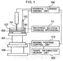
- Fig. 1 shows embodiment 1 where the present invention is utilised to fabricate a part.
- the present embodiment is structured by an object to be machined 103 immersed in a machining solution 102 within a machining solution container 101, a machining electrode 104 arranged oppositely to the object to be machined 103 to electrolytically machine the object to be machined 103, a reference electrode 105 as a reference in electrode potential, a potential/current control unit 106 for controlling the potential and current on the machining electrode 104, an XY-axis stage 107 for moving the object to be machined 103 in X-axis and Y-axis directions (horizontal directions), a z-axis stage installed beneath the machining solution container 101 to move the object to be machined 103 in a z-axis direction (vertical direction), a shape information memory unit 109 for memorising arbitrary shape information, a moving position control unit 110 for controlling the movement of the XY stage 107 and the z stage 108 based on the shape
- the potential/current control unit 106 is provided, for example, with a machining electrode circuit 106A called potentio galvanostat, a micro-computer for controlling the potential on the machining electrode 104 of the machining electrode circuit 106A and the current etc. flowing between the machining electrode 104 and the object to be machined 103, and various operating keys for operation.
- a machining electrode circuit 106A called potentio galvanostat
- a micro-computer for controlling the potential on the machining electrode 104 of the machining electrode circuit 106A and the current etc. flowing between the machining electrode 104 and the object to be machined 103, and various operating keys for operation.
- the machining electrode circuit 106A is structured, for example as shown in Fig. 2, by a variable resistance 202 connected to a plus side of a constant voltage power supply 201, an operational amplifier 203 connected to the variable resistance 202, an opposite electrode (machining electrode) 104 connected to an output section of the operational amplifier 203, an acting pole (object to be machined) 103 oppositely arranged to the opposite electrode (machining electrode) 104 and connected to a minus side of the constant voltage power supply 201, and a reference electrode 105 as a reference to measure the potential on the acting pole (object to be machined) 103.
- the machining electrode 104 is a rod form member sharp-edged at its tip opposite to a surface to be machined and exposed at only one portion of a tip end with other portions coated by an insulator. Also, the material of the rod member uses, for example, carbon, tungsten, platinum or the like.
- the reference electrode 105 is, for example, a glass cylindrical member having a solution passage provided at a tip on a side to be immersed in a machining solution and a silver thin wire provided in a centre of the cylindrical member to reach a glass film, wherein a silver chloride solution is filled in a manner immersing the thin wire.
- the reference electrode 105 is not required to control the potential on the machining electrode 104 and the object to be machined 103, i.e. it is not necessarily required when only performing current control between the machining electrode 104 and the object to be machined 103.
- this machining electrode circuit 106A it is possible to control the current flowing between the opposite electrode (machining electrode) 104 and the acting pole (object to be machined) 103 to a current required for electrolytic machining by varying the resistance value of the variable resistance 202.
- the XY-axis stage 107 and the Z-axis stage 108 are moved in the XY-axis direction and the Z-axis direction by an electrical drive means under the control of the moving position control unit 110.
- the Z-axis stage 108 is first moved in the Z-axis direction by a distance control means to control the space distance between the machining electrode 104 and the object to be machined 103 to a predetermined spacing, and then a predetermined voltage is applied between the machining electrode 104 and the object to be machined 103 to cause a constant current to flow between the machining electrode 104 and the object to be machined 103.
- the XY stage 107 and the Z-stage 108 are driven by the moving position control unit 110 based on shape information memorised by the shape information memory unit 109, in order to move the machining electrode along a shape of a part to be fabricated above the object to be machined.
- the above process is hereinafter referred to as an electrolytic machining process.
- the distance control means for example first controls, through the current/potential control unit 106. the current flowing between the object to be machined 103 and the machining electrode 104 to nearly zero, and then slowly moves the Z-axis stage upward to cause the object to be machined 103 to approach the machining electrode 104 while measuring the potential on the object to be measured. Because if the object to be machined 103 is brought into contact with the machining electrode 104 due to this ascending motion the potential of the object to be machined 103 greatly varies, the position on the Z-axis at this time is determined as the zero spacing position.
- the Z-axis stage 108 is driven under the control of the moving position control unit 110 to control the space distance between the machining electrode 104 and the object to be machined 103 to a desired spacing.
- a method can be considered that the space distance is measured by a laser measuring device.
- the machining solution changing mechanism 111 is structured, for example as shown in Fig. 3, by a machining solution tank (A) 302A containing a machining solution (A) 102A used when fabricating a cast mold by subjecting the object to be machined 103 to a removal process, a machining tank (B) 302B containing a machining solution (B) 102B used upon forming a metal layer, a machining solution tank (C) 302C containing a machining solution (C) 102C used upon forming a part, a machining solution tank (D) 302D containing a machining solution (D) 102D used upon dissolving a metal, a cleaning solution tank 303 containing a cleaning solution 301 used for cleaning the machining solution container 101 during changing the machining solution, a solution feed pump (A) 306A connected to the machining solution tank (A) 302A to feed the machining solution (A) 102A within the machining solution tank (A) 302A to the machining
- the machining solution changing mechanism 111 can supply a required amount of a solution from the tank containing a machining solution or cleaning solution required for machining to the machining solution container 101, and discharge the machining solution from the machining solution container 101.
- the solution feed pump (F) 308 is first driven to discharge the machining solution in the machining solution container 101 to the waste solution tank 304, as shown in Fig. 4. Then the solution feed pump (E) is driven to supply the cleaning solution 301 in the cleaning solution tank 303 to the machining solution container 101, and the solution feed pump (F) 308 is again driven to discharge the cleaning solution 31 in the machining solution container 101 into the waste solution tank 304.
- a solution feed pump which is connected to a machining solution tank containing a required machining solution among the machining solution (A) 102A, machining solution (B) 102B, machining solution (C) 102C and machining solution (D) 102D, is driven to supply the machining solution to the machining solution container 101.
- This process is hereinafter referred to as a machining solution changing process.
- the procedure of a part fabricating method according to the present embodiment will be explained hereinbelow based on Fig. 5 and Fig. 6.
- First the shape information for a part to be fabricated is memorised in the shape information memory unit 109.
- the machining solution (A) 102A as a machining solution for removal process is supplied into the machining solution container 101 by the machining solution changing mechanism 111.
- an object to be machined 103 shown in Fig. 6(a) is subjected to removal process, thus fabricating a cast mold 501 for parts as shown in Fig. 6(b).
- the machining solution in the machining solution container 101 is changed, through the aforesaid machining solution changing process, from the machining solution (A) 102A as a machining solution for removal process to a machining solution (B) 102B as a machining solution for forming a metal layer. Then an additional machining is performed through the aforesaid electrolyte machining to deposit a metal A on a surface of the cast mold 501 as shown in Fig. 6(C), thus forming a metal layer 502.
- the machining solution in the machining solution container 101 is changed. through the aforesaid machining solution changing process, from the machining solution (B) 102B as a machining solution for metal layer formation to a machining solution (C) 102C as a machining solution for electro-forming. Then additional machining is performed, through the electrolyte machining, on an inside of the cast mold 501 to deposit a metal B as shown in Fig. 6(d), thus forming a part 503.
- machining solution in the machining solution container 101 is changed, through the machining solution changing process, from the machining solution (C) 102C as a machining solution for electro-forming to a machining solution (D) 102D as a machining solution for metal layer dissolution to dissolve a metal layer 502 as shown in Fig. 6(e), removing the part 503 formed inside the cast mold 501.
- a method to dissolve the metal layer 502 is considered a method of using a solution for selectively dissolving only the metal A, a method applying a voltage to selectively dissolve only the metal A, or the like.
- the distance between the tip of the machining electrode and a surface to be machined of an object to be machined is controlled to a predetermined spacing by utilising a sharp-edged machining electrode, and thereafter machining is performed such that the machining electrode is moved along the shape of a part to be fabricated above a surface to be machined of the object to be machined, it is possible to fabricate simply a part having a complicated three dimensional form without the necessity of fabricating a machining electrode corresponding to a machining form. Also, because the machining is performed in a state of out of contact between the machining electrode and the object to be machined, there is less consumption of machining electrodes.
- the machining is performed by the electro-forming method utilising an electrochemical reaction, it is possible to perform machining with extremely low energy as compared with the electric discharge machining without changing the hardness and toughness of the object to be machined. Further, since the part fabricating apparatus in the present embodiment is provided with the machining solution changing mechanism, automation of part fabrication is readily realised.
- the machining electrode used was a platinum-iridium alloy wire sharp-edged at its tip to a tip diameter of 1 ⁇ m and coated by resin at other than the tip wherein a chromium substrate was used as an object to be machined.
- a chromium electrolytic etch solution mixed with 62.7 g/l of a sulfamic acid and 37.3 g/l of a boric acid was used as a machining solution for the removal process
- a gold plating solution mixed with 7.4g/l of potassium dicyanoaurarate (I) and 70 g/l of tri-sodium citrate as a machining solution for metal layer formation
- the procedure for fabricating a gear was performed along with a procedure shown in Fig. 5, wherein gear shape information was first memorised in a shape information memory unit 109, the chromium substrate was then subjected to the removal process to fabricate a gear cast mold, gold was then deposited on a surface of the cast mold, nickel was then deposited inside the cast mold to form the part, and finally the gold layer was dissolved to take the part out.
- a gold layer with a thickness of 2 ⁇ m was formed on the surface of the cast mold.
- the gold layer was dissolved by a gold etch solution with the result that a gear having a diameter of 800 ⁇ m and a thickness of 80 ⁇ m could be taken out.
- Embodiment 1 has a structure almost similar to Embodiment 1 as shown in Fig. 7, it is characterised in that the Z-axis stage 108 is arranged on the XY stage 107 and further the work electrode 104 is attached to the Z-axis stage 108 through a machining electrode attaching arm 113.
- the XY stage 107 moves in the XY directions and the Z-axis stage 108 in the Z-axis direction, causing the machining electrode 104 to follow the attaching arm 113 and hence move in the XY-axis directions and Z-axis direction.
- This also provides a similar effect to Embodiment 1.
- Embodiment 1 is structured almost similar to Embodiment 1 as shown in Fig. 8, it is characterised in that a machining electrode changing mechanism 701 is arranged therein which can exchange the machining electrode for use in machining.
- the machining electrode changing mechanism 701 is provided with, for example as shown in Fig. 9, a machining electrode attaching arm 113 attached with machining electrode (104A) and machining electrode (104B) different in tip diameter, and an about-Z-axis rotation mechanism for rotating the machining electrode attaching arm about the Z-axis, so that the machining electrode to be used can be positioned above a surface to be machined of an object to be machined 103 immersed in a machining solution.
- the present embodiment can use a plurality of machining electrodes different in tip diameter, it is possible to select a machining electrode suitable for a shape of a portion to be machined or kind of machining.
- the present invention provides the following effects.
Landscapes
- Engineering & Computer Science (AREA)
- Chemical & Material Sciences (AREA)
- Mechanical Engineering (AREA)
- Chemical Kinetics & Catalysis (AREA)
- Electrochemistry (AREA)
- Materials Engineering (AREA)
- Metallurgy (AREA)
- Organic Chemistry (AREA)
- Physics & Mathematics (AREA)
- Thermal Sciences (AREA)
- Electrical Discharge Machining, Electrochemical Machining, And Combined Machining (AREA)
- Micromachines (AREA)
Abstract
Description
- The present invention relates to a part fabricating method and part fabricating apparatus for fabricating parts in the fields of metal industry, electronic industry, machinery industry and so on.
- In the conventional part fabricating methods, there has been a method utilisation a machining technology or electric discharge technology to remove unwanted portions of objects to be machined into a desired shape thus fabricating parts. In the method utilising a machining technology, parts have been fabricated using a cutting tool wherein any of the cutting tool and object to be machined is rotated to bring the cutting tool and the object to be machined into contact at the same time, thereby removing unwanted portions of the object to be machined into a desired shape. In the method utilising an electronic discharge technology, parts have been fabricated by making a machining electrode having a corresponding tip shape to a desired machining from wherein the machining electrode and the object to be machined are adjusted to a predetermined distance to repeatedly cause pulse-formed electric discharge between the machining electrode and the object to be machined, thus removing unnecessary portions of the object to be machined.
- However, there have been some problems in the conventional part fabrication methods. First, the following points can be listed as the problems encountered in the machining technology.
- (1) Because only removal machining is possible, there may be a case that the efficiency of material utilisation is extremely worsened as a consequence of the part fabricating shape, or a long machining time is required even for a simple shape.
- (2) Because machinable shapes are limited by the kind of machining machine used, the fabrication of parts having complicated shapes requires many kinds of machining machines with increased process steps.
- (3) When the operation includes contacting a cutting tool with an object to be machined, consumption of the cutting tool is unavoidable. Because the consumption of the cutting tool raises a problem of lowering machining accuracy or roughening in the machining surface, the cutting tool must be exchanged as required and full automation for part fabrication is difficult.
- (4) Because removal machining is effected by utilising a physical force caused between a cutting tool and an object to be machined, there is a restriction on the hardness or toughness of the object to be machine. Accordingly, there is a necessity of adjusting the cutting tool kind and machining conditions in compliance with the material of the object to be machined.
- (5) The machining resolution increases with decrease in tip diameter of a cutting tool, whereas there is limitation in cutting tool sharp-edging due to a machining utilising a physical force. Accordingly, there is difficulty in coping with miniaturisation for fabrication parts.
-
- Next, the following points can be listed as problems encountered in the method utilising the electric discharge technology.
- (1) Because the forming shape of an object to be machined is determined by a tip shape of the machining electrode, before performing machining the machined electrode must have been previously made to have a corresponding tip shape to a desired forming shape.
- (2) Because only removal machining is possible similarly, to machining, there may be a case that the efficiency of material utilisation is extremely worsened as a consequence of the part fabricating shape or a long machining time is required even for a simple shape.
- (3) Consumption of the machining electrode is unavoidable similarly, and the machining electrode has to be exchanged as required. In the electric discharge machining, the exchange of the machining electrode, each time, requires fabrication of a machining electrode having a corresponding tip shape to a forming shape, thus worsening machining efficiency.
- (4) Removal chips produced in machining adhere to a surface to be machined, having bad effects upon machining accuracy.
- (5) In order to cause pulse-formed electric discharge required upon removal machining, a great voltage has to be applied, thus increasing energy consumption during machining.
- (6) Because a machining electrode having a corresponding tip form to a desired part shape is utilised to effect removal from a surface to be machined, the direction of machining progression is only in a depth direction of the object to be machined and there is difficulty in fabricating parts having a complicated three-dimensional shape.
-
- The present inventions provides a means to mitigate the above-stated problems.
- In order to mitigate the above-stated problems, the present invention is characterised by fabricating a part by: first performing removal machining on an object to be machined to fabricate a part cast mold, then depositing a metal A on a surface of the cast mold to form a metal A layer, depositing a metal B different in kind from the metal inside the cast mold to form a part, and finally selectively removing the metal A to take out the part.
- Also, in a process of the cast mold fabrication, metal layer formation or part formation, the removal machining or metal deposition is effected by an electrolytic machining method wherein the object to be machined and a machining electrode are opposite placed in an electrolytic solution to cause electrochemical reaction for machining between a surface to be machined of the object to be machined and a tip of the machining electrode. Here, a sharp-edged electrode may be used as the machining electrode.
- Also, in a process of the cast mold fabrication, metal layer formation or part formation, machining is made while moving the machining electrode or object to be machined along an arbitrary shape.
- Also, according to one aspect of the invention a part fabricating apparatus is characterised by comprising: an object to be machined holding means for holding an object to be machined in an electrolytic solution, a machining electrode for subjecting machining in a surface to be machined of the object to be machined through electrochemical reaction, a spacing changing means for detecting and changing a spacing between the surface to be machined of the object to be machined held by the object to be machined holding means and the machining electrode, a potential/current control unit for controlling a potential/current on the machining electrode, an electrolytic solution changing means for arbitrary changing an electrolytic solution A for effecting removal machining on the surface to be machined to fabricate a cast mold, an electrolytic solution B for depositing a metal A on a surface of the cast mold to form the metal layer A, and an electrolytic solution C for depositing the metal B inside the cast mold to form a part.
- The part fabricating apparatus is provided with the machining electrode, for example, sharp-edged, in order to increase machining accuracy.
- Also, the part fabricating apparatus is provided, as a means to move the machining electrode and the object to be machined along an arbitrary shape in a process of the cast mold fabrication, metal layer formation or part formation, with a shape information memory means for memorising arbitrary shape information and a moving position control means for moving the machining electrode or object to be machined along an arbitrary shaped based on shape information memorised in the shape information memory means.
- Also, the part fabricating apparatus is provided, as a means to use a plurality of machining electrodes, with a machining electrode holding means for holding the plurality of machining electrodes, and a machining electrode changing means for arbitrarily changing between the plurality of machining electrodes held by the machining electrode holding means.
- Embodiments of the invention will now be described by way of further example only and with reference to the accompanying drawings, in which:-
- Fig. 1 is a typical diagram showing a first embodiment of a part fabricating apparatus of the present invention;
- Fig. 2 is a circuit diagram showing an example of a constant current circuit used in an embodiment of the present invention;
- Fig. 3 is a typical diagram showing an example of a machining solution changing mechanism according to Fig. 1;
- Fig. 4 is a flowchart showing a procedure for changing machining solutions;
- Fig. 5 is a flowchart showing a part fabricating method according to an embodiment of the present invention:
- Fig. 6A, 6B, 6C, 6D and 6E are process sectional views showing a process for part fabrication according to the present invention;
- Fig. 7 is a typical diagram showing a second embodiment of a part fabricating apparatus of the present invention;
- Fig. 8 is a typical diagram showing a third embodiment of a part fabricating apparatus of the present invention; and
- Fig. 9 is an explanatory view showing an example of a machining electrode changing mechanism used in the part fabricating apparatus of Fig. 8.
-
- Fig. 1 shows
embodiment 1 where the present invention is utilised to fabricate a part. The present embodiment is structured by an object to be machined 103 immersed in amachining solution 102 within amachining solution container 101, amachining electrode 104 arranged oppositely to the object to be machined 103 to electrolytically machine the object to be machined 103, areference electrode 105 as a reference in electrode potential, a potential/current control unit 106 for controlling the potential and current on themachining electrode 104, an XY-axis stage 107 for moving the object to be machined 103 in X-axis and Y-axis directions (horizontal directions), a z-axis stage installed beneath themachining solution container 101 to move the object to be machined 103 in a z-axis direction (vertical direction), a shapeinformation memory unit 109 for memorising arbitrary shape information, a movingposition control unit 110 for controlling the movement of theXY stage 107 and thez stage 108 based on the shape information memorised by the shapeinformation memory unit 109, a machiningsolution changing mechanism 111 connected to themachining solution container 101 to feed amachining solution 102 to and from an inside and outside themachining solution container 101. - The potential/
current control unit 106 is provided, for example, with amachining electrode circuit 106A called potentio galvanostat, a micro-computer for controlling the potential on themachining electrode 104 of themachining electrode circuit 106A and the current etc. flowing between themachining electrode 104 and the object to be machined 103, and various operating keys for operation. - The
machining electrode circuit 106A is structured, for example as shown in Fig. 2, by avariable resistance 202 connected to a plus side of a constantvoltage power supply 201, anoperational amplifier 203 connected to thevariable resistance 202, an opposite electrode (machining electrode) 104 connected to an output section of theoperational amplifier 203, an acting pole (object to be machined) 103 oppositely arranged to the opposite electrode (machining electrode) 104 and connected to a minus side of the constantvoltage power supply 201, and areference electrode 105 as a reference to measure the potential on the acting pole (object to be machined) 103. - The
machining electrode 104 is a rod form member sharp-edged at its tip opposite to a surface to be machined and exposed at only one portion of a tip end with other portions coated by an insulator. Also, the material of the rod member uses, for example, carbon, tungsten, platinum or the like. - Also, the
reference electrode 105 is, for example, a glass cylindrical member having a solution passage provided at a tip on a side to be immersed in a machining solution and a silver thin wire provided in a centre of the cylindrical member to reach a glass film, wherein a silver chloride solution is filled in a manner immersing the thin wire. Thereference electrode 105 is not required to control the potential on themachining electrode 104 and the object to be machined 103, i.e. it is not necessarily required when only performing current control between themachining electrode 104 and the object to be machined 103. - According to this
machining electrode circuit 106A, it is possible to control the current flowing between the opposite electrode (machining electrode) 104 and the acting pole (object to be machined) 103 to a current required for electrolytic machining by varying the resistance value of thevariable resistance 202. - The XY-
axis stage 107 and the Z-axis stage 108 are moved in the XY-axis direction and the Z-axis direction by an electrical drive means under the control of the movingposition control unit 110. - In electrical machining, the Z-
axis stage 108 is first moved in the Z-axis direction by a distance control means to control the space distance between themachining electrode 104 and the object to be machined 103 to a predetermined spacing, and then a predetermined voltage is applied between themachining electrode 104 and the object to be machined 103 to cause a constant current to flow between themachining electrode 104 and the object to be machined 103. At the same time, theXY stage 107 and the Z-stage 108 are driven by the movingposition control unit 110 based on shape information memorised by the shapeinformation memory unit 109, in order to move the machining electrode along a shape of a part to be fabricated above the object to be machined. The above process is hereinafter referred to as an electrolytic machining process. - The distance control means for example first controls, through the current/
potential control unit 106. the current flowing between the object to be machined 103 and themachining electrode 104 to nearly zero, and then slowly moves the Z-axis stage upward to cause the object to be machined 103 to approach themachining electrode 104 while measuring the potential on the object to be measured. Because if the object to be machined 103 is brought into contact with themachining electrode 104 due to this ascending motion the potential of the object to be machined 103 greatly varies, the position on the Z-axis at this time is determined as the zero spacing position. Taking this position as a reference, the Z-axis stage 108 is driven under the control of the movingposition control unit 110 to control the space distance between themachining electrode 104 and the object to be machined 103 to a desired spacing. Besides this method, a method can be considered that the space distance is measured by a laser measuring device. - The machining
solution changing mechanism 111 is structured, for example as shown in Fig. 3, by a machining solution tank (A) 302A containing a machining solution (A) 102A used when fabricating a cast mold by subjecting the object to be machined 103 to a removal process, a machining tank (B) 302B containing a machining solution (B) 102B used upon forming a metal layer, a machining solution tank (C) 302C containing a machining solution (C) 102C used upon forming a part, a machining solution tank (D) 302D containing a machining solution (D) 102D used upon dissolving a metal, acleaning solution tank 303 containing acleaning solution 301 used for cleaning themachining solution container 101 during changing the machining solution, a solution feed pump (A) 306A connected to the machining solution tank (A) 302A to feed the machining solution (A) 102A within the machining solution tank (A) 302A to themachining solution container 101, a solution feed pump (B) 306B connected to the machining solution tank (B) 302B to feed the machining solution (B) 102B within the machining solution tank (B) 302B to themachining solution container 101, a solution feed pump (C) 306C connected to the machining solution tank (C) 302C to feed the machining solution (C) 102C within the machining solution tank (C) 302C to themachining solution container 101, a solution feed pump (D) 306D connected to the machining solution tank (D) 302D to feed the solution within the machining solution tank (D) 302D to themachining solution container 101, a solution feed pump (E) 307 connected to thecleaning solution tank 303 to feed thesolution 301 within thecleaning solution tank 303 to themachining solution container 101, awaste solution tank 304 for reserving awaste solution 305 discharged from themachining solution container 101, and a solution feed pump (F) 308 for feeding a solution to thewaste solution tank 304 upon discharging the solution. - The machining
solution changing mechanism 111 can supply a required amount of a solution from the tank containing a machining solution or cleaning solution required for machining to themachining solution container 101, and discharge the machining solution from themachining solution container 101. - During changing the machining solution. the solution feed pump (F) 308 is first driven to discharge the machining solution in the
machining solution container 101 to thewaste solution tank 304, as shown in Fig. 4. Then the solution feed pump (E) is driven to supply thecleaning solution 301 in thecleaning solution tank 303 to themachining solution container 101, and the solution feed pump (F) 308 is again driven to discharge the cleaning solution 31 in themachining solution container 101 into thewaste solution tank 304. Then a solution feed pump, which is connected to a machining solution tank containing a required machining solution among the machining solution (A) 102A, machining solution (B) 102B, machining solution (C) 102C and machining solution (D) 102D, is driven to supply the machining solution to themachining solution container 101. This process is hereinafter referred to as a machining solution changing process. - The procedure of a part fabricating method according to the present embodiment will be explained hereinbelow based on Fig. 5 and Fig. 6. First the shape information for a part to be fabricated is memorised in the shape
information memory unit 109. Then the machining solution (A) 102A as a machining solution for removal process is supplied into themachining solution container 101 by the machiningsolution changing mechanism 111. Then an object to be machined 103 shown in Fig. 6(a) is subjected to removal process, thus fabricating acast mold 501 for parts as shown in Fig. 6(b). - Then the machining solution in the
machining solution container 101 is changed, through the aforesaid machining solution changing process, from the machining solution (A) 102A as a machining solution for removal process to a machining solution (B) 102B as a machining solution for forming a metal layer. Then an additional machining is performed through the aforesaid electrolyte machining to deposit a metal A on a surface of thecast mold 501 as shown in Fig. 6(C), thus forming ametal layer 502. - Then the machining solution in the
machining solution container 101 is changed. through the aforesaid machining solution changing process, from the machining solution (B) 102B as a machining solution for metal layer formation to a machining solution (C) 102C as a machining solution for electro-forming. Then additional machining is performed, through the electrolyte machining, on an inside of thecast mold 501 to deposit a metal B as shown in Fig. 6(d), thus forming apart 503. - Finally the machining solution in the
machining solution container 101 is changed, through the machining solution changing process, from the machining solution (C) 102C as a machining solution for electro-forming to a machining solution (D) 102D as a machining solution for metal layer dissolution to dissolve ametal layer 502 as shown in Fig. 6(e), removing thepart 503 formed inside thecast mold 501. - Here, as a method to dissolve the
metal layer 502 is considered a method of using a solution for selectively dissolving only the metal A, a method applying a voltage to selectively dissolve only the metal A, or the like. - In the present embodiment, because the distance between the tip of the machining electrode and a surface to be machined of an object to be machined is controlled to a predetermined spacing by utilising a sharp-edged machining electrode, and thereafter machining is performed such that the machining electrode is moved along the shape of a part to be fabricated above a surface to be machined of the object to be machined, it is possible to fabricate simply a part having a complicated three dimensional form without the necessity of fabricating a machining electrode corresponding to a machining form. Also, because the machining is performed in a state of out of contact between the machining electrode and the object to be machined, there is less consumption of machining electrodes. Also, because the machining is performed by the electro-forming method utilising an electrochemical reaction, it is possible to perform machining with extremely low energy as compared with the electric discharge machining without changing the hardness and toughness of the object to be machined. Further, since the part fabricating apparatus in the present embodiment is provided with the machining solution changing mechanism, automation of part fabrication is readily realised.
- In an experimental example of fabricating a gear having a diameter of 800 µm by applying the present embodiment thereto, the machining electrode used was a platinum-iridium alloy wire sharp-edged at its tip to a tip diameter of 1 µm and coated by resin at other than the tip wherein a chromium substrate was used as an object to be machined. Also, a chromium electrolytic etch solution mixed with 62.7 g/l of a sulfamic acid and 37.3 g/l of a boric acid was used as a machining solution for the removal process, a gold plating solution mixed with 7.4g/l of potassium dicyanoaurarate (I) and 70 g/l of tri-sodium citrate as a machining solution for metal layer formation, a nickel plating solution mixed with 350 g/l of nickel sulfamate and 30 g/l of a boric acid as a machining solution for part formation, and a gold etch solution mixed with 25 g/l of iodine and 100 g/l of potassium iodide as a machining solution for metal layer dissolution.
- The procedure for fabricating a gear was performed along with a procedure shown in Fig. 5, wherein gear shape information was first memorised in a shape
information memory unit 109, the chromium substrate was then subjected to the removal process to fabricate a gear cast mold, gold was then deposited on a surface of the cast mold, nickel was then deposited inside the cast mold to form the part, and finally the gold layer was dissolved to take the part out. - In the chrome substrate removal process in cast mold fabrication, the distance between the tip of the machining electrode and the surface of the chromium substrate was controlled to 10 µm, and a current pulse of Ion = 1000 µA, Ton = 0.3 second and Toff = 0.3 second was applied by the potential/current control unit while controlling the XY table to be moved according to the gear shape information. Then this was repeated 20 times, with the result that a gear cast mold with a depth of 100 µm was fabricated.
- In the gold deposition in metal layer formation, the distance between the tip of the machining electrode and the surface of the cast mold was controlled to 10 µm, and a current pulse of Ion = -400 µA, Ton = 0.3 second and Toff = 0.3 second was applied by the potential/current control unit while controlling the XY table to be moved according to the gear shape information. As a result, a gold layer with a thickness of 2 µm was formed on the surface of the cast mold.
- In the nickel deposition in metal layer formation, the distance between the tip of the machining electrode and the surface of the cast mold was controlled to 10 µm, and a current pulse of Ion = -1000 µA, Ton = 0.3 second and Toff = 0.3 second was applied by the potential/current control unit while controlling the XY table to be moved according to the gear shape information. Further the Z-axis stage was driven by the moving distance control unit so that the distance between the tip of the machining electrode and the machining surface becomes 10 µm. This was repeated 16 times with the result that a nickel gear part with a thickness of 80 µm was formed on the surface of the cast mold.
- The gold layer was dissolved by a gold etch solution with the result that a gear having a diameter of 800 µm and a thickness of 80 µm could be taken out.
- Although the present embodiment has a structure almost similar to
Embodiment 1 as shown in Fig. 7, it is characterised in that the Z-axis stage 108 is arranged on theXY stage 107 and further thework electrode 104 is attached to the Z-axis stage 108 through a machiningelectrode attaching arm 113. - In operation of this apparatus, the
XY stage 107 moves in the XY directions and the Z-axis stage 108 in the Z-axis direction, causing themachining electrode 104 to follow the attachingarm 113 and hence move in the XY-axis directions and Z-axis direction. This also provides a similar effect toEmbodiment 1. - Although the embodiment is structured almost similar to
Embodiment 1 as shown in Fig. 8, it is characterised in that a machiningelectrode changing mechanism 701 is arranged therein which can exchange the machining electrode for use in machining. - The machining
electrode changing mechanism 701 is provided with, for example as shown in Fig. 9, a machiningelectrode attaching arm 113 attached with machining electrode (104A) and machining electrode (104B) different in tip diameter, and an about-Z-axis rotation mechanism for rotating the machining electrode attaching arm about the Z-axis, so that the machining electrode to be used can be positioned above a surface to be machined of an object to be machined 103 immersed in a machining solution. - This also provided similar effects to
Embodiment 1. - In addition, because the present embodiment can use a plurality of machining electrodes different in tip diameter, it is possible to select a machining electrode suitable for a shape of a portion to be machined or kind of machining. The smaller the tip diameter of the machining electrode the higher the machining resolution increases, lowering the machining speed. Accordingly, where high resolution is not required, the use of a machining electrode having a somewhat great tip diameter improves machining efficiency. Accordingly, because the present embodiment makes it possible to selectively use a machining electrode having a tip diameter suited for a machining shape and machining resolution required, machining time could be reduced with high machining accuracy being maintained.
- The present invention provides the following effects.
- (1) Because the cast mold is first fabricated to form a part inside the cast mold and thereafter it is taken out, it is possible to utilise one cast mold many times with manufacture efficiency raised when fabricating, for example, a great volume of parts of the same shape.
- (2) Because machining is effected in a non-contact state of the tip of the machining electrode with the surface to be machined of the object to be machined, there is almost no consumption of machining electrodes. Accordingly, it is possible to implement machining for a long time without exchanging the machining electrode, readily realising full automation for part fabrication.
- (3) Because in electrolytic machining electrochemical reactions are utilised that occur between the surface to be machined of an object to be machined and the tip of a machining electrode without involvement of physical force, there is no restriction on the hardness or toughness of an object to be machined. Accordingly, it is possible to perform machining on a material that is difficult to machine by conventional machining operations.
- (4) The increase in machining operation resolution is facilitated by reducing the tip diameter of the machining electrode, making it easy to cope with miniaturisation for parts to be fabricated.
- (5) Because part formation is performed by additional machining, the efficiency of material utilisation is high making it possible to fabricate parts having such a shape that is impossible to fabricate only by a removal process.
- (6) By using a sharp-edged electrode as the machining electrode to machine while moving the machining electrode and an object to be machined according to an arbitrary form, it is possible to fabricate complicated three-dimensional shaped parts through less processing with simplification by the same apparatus. Also, there is no necessity of fabricating a machining electrode having a corresponding tip form to a machining form.
- (7) In the electrolytic machining, the utilisation of electrochemical reactions will not produce chips even during removal machining. There is no adverse effect of chips on machining accuracy.
- (8) The electrochemical reaction utilised for electrolytic machining can be caused by low application voltage, thus being low in energy consumption as compared with electric discharge machining.
- (9) The provision of the solution changing means capable of changing the solution easily realises an automation for part fabrication.
-
Claims (10)
- A part fabricating method comprising the steps of:performing removal machining on an object to be machined to fabricate a part cast mold;depositing a first metal on a surface of the cast mold to form a first metal layer;depositing a second metal different in kind from the first metal inside the cast mold to form a part; andselectively removing the first metal to take out the part.
- A part fabricating method as claimed in claim 1, wherein in the process of fabricating the cast mold, the removal machining is effected by an electrolytic machining method wherein the object to be machined and a machining electrode are placed opposite each other in an electrolytic solution to cause electrochemical reaction for machining between a surface to be machined of the object to be machined and a tip of the machining electrode.
- A part fabricating method as claimed in claim 1, wherein in the process of forming the first metal layer, the deposition of the first metal is effected by an electrolytic machining method wherein an electrochemical reaction is caused between a surface to be machined of the object to be machined and a tip of a machining electrode to deposit the first metal.
- A part fabricating method as claimed in claim 1, wherein in the process of forming the part, the deposition of the second metal is effected by an electrolytic machining method wherein an electrochemical reaction is caused between the first metal layer and a tip of a machining electrode to deposit the second metal.
- A part fabricating method as claimed in claim 1, wherein a sharp-edged electrode is used as the machining electrode.
- A part fabricating method as claimed in claim 1, wherein in the process of fabricating the cast mold, forming the metal layer or forming the part, machining is effected while moving at least one of the machining electrode or the object to be machined according to stored shape information.
- A part fabricating apparatus comprising:an object to be machined holding means for holding an object to be machined in an electrolytic solution;a machining electrode for performing machining in a surface to be machined of the object to be machined through electrochemical reaction;a spacing changing means for detecting and changing a spacing between the surface to be machined of the object to be machined held by the object to be machined holding means and the machining electrode;a potential/current control unit for controlling a potential/current of the machining electrode;a first electrolytic solution for effecting removal machining on the surface to be machined to fabricate a cast mold;a second electrolytic solution for depositing a first metal on a surface of the cast mold to form the first metal layer; andan electronic solution changing means for changing a third electrolytic solution for depositing the second metal inside the cast mold to form a part.
- A part fabricating apparatus as claimed in claim 7, wherein the machining electrode is a sharp-edged electrode.
- A part fabricating apparatus as claimed in claim 7, further comprising:a shape information memory means for memorising shape information; anda moving position control means for moving the machining electrode or object to be machined according to shape based on shape information memorised in the shape information memory means.
- A part fabricating apparatus as claimed in claim 7, further comprising:a plurality of machining electrodes;a machining electrode holding means for holding the plurality of machining electrodes; anda machining electrode changing means for changing between the plurality of machining electrodes held by the machining electrode holding means.
Applications Claiming Priority (2)
| Application Number | Priority Date | Filing Date | Title |
|---|---|---|---|
| JP33290297 | 1997-12-03 | ||
| JP33290297A JP3217999B2 (en) | 1997-12-03 | 1997-12-03 | Component manufacturing method and component manufacturing device |
Publications (3)
| Publication Number | Publication Date |
|---|---|
| EP0920946A2 true EP0920946A2 (en) | 1999-06-09 |
| EP0920946A3 EP0920946A3 (en) | 2002-12-04 |
| EP0920946B1 EP0920946B1 (en) | 2004-05-26 |
Family
ID=18260086
Family Applications (1)
| Application Number | Title | Priority Date | Filing Date |
|---|---|---|---|
| EP98309928A Expired - Lifetime EP0920946B1 (en) | 1997-12-03 | 1998-12-03 | Part fabricating method and part fabricating apparatus |
Country Status (4)
| Country | Link |
|---|---|
| US (2) | US6221228B1 (en) |
| EP (1) | EP0920946B1 (en) |
| JP (1) | JP3217999B2 (en) |
| DE (1) | DE69824125T2 (en) |
Cited By (6)
| Publication number | Priority date | Publication date | Assignee | Title |
|---|---|---|---|---|
| US7097729B2 (en) | 1998-11-19 | 2006-08-29 | C.I.R.T.E.S. (Centre D'ingenierie De Recherche Et De Transfert De L'esstin A Saint-Die) | Method for making mechanical parts by decomposition into layers |
| SG155059A1 (en) * | 2003-06-11 | 2009-09-30 | Ishikawajima Harima Heavy Ind | Repair method for machine component, production method of restored machine component, production method of machine component, gas turbine engine, electric spark machine, repair method for turbine component and production method for restored turbine compo |
| US7607211B2 (en) * | 2000-05-15 | 2009-10-27 | Centre d'Ingéniérie de Recherche et de Transfert de l'Esstin à Saint Die (C.I.R.T.E.S.) | Device for producing plates designed for a fast prototyping process, method for machining and assembling said plates and resulting plates and prototype workpieces |
| US7920937B2 (en) | 2002-10-07 | 2011-04-05 | Cirtes SRC, SA Cooperative d'Ues | Mechanical component having at least one fluid transport circuit and method for designing same in strata |
| CN103894689A (en) * | 2012-12-27 | 2014-07-02 | 财团法人金属工业研究发展中心 | Electric machining method and device and reference position detection method for electric machining |
| CN110842307A (en) * | 2019-11-22 | 2020-02-28 | 合肥工业大学 | Electrochemical machining tool for complex inner wall structure with poor accessibility |
Families Citing this family (10)
| Publication number | Priority date | Publication date | Assignee | Title |
|---|---|---|---|---|
| US6735844B2 (en) * | 2001-01-19 | 2004-05-18 | Honeywell International Inc. | Method for fabricating a plastic optic element injection mold |
| US6948240B2 (en) * | 2001-10-05 | 2005-09-27 | Benq Corporation | Method for shaping an object |
| US20050247569A1 (en) * | 2004-05-07 | 2005-11-10 | Lamphere Michael S | Distributed arc electroerosion |
| US7867374B2 (en) * | 2004-10-01 | 2011-01-11 | Federal-Mogul World Wide, Inc. | Active matrix electrochemical machining apparatus and method |
| DE102007043066A1 (en) * | 2007-09-10 | 2009-03-12 | Robert Bosch Gmbh | Method and device for electrochemical machining |
| JP5423222B2 (en) * | 2009-08-07 | 2014-02-19 | ソニー株式会社 | Position detection apparatus and position detection method |
| CN101880907B (en) * | 2010-07-07 | 2012-04-25 | 厦门大学 | Electrochemical levelling and polishing processing method with nanometer precision and device thereof |
| WO2015006647A1 (en) * | 2013-07-12 | 2015-01-15 | The Regents Of The University Of Michigan | Adapting electroforming techniques for the manufacture of architectural building elements |
| CN107206518B (en) | 2014-11-26 | 2019-05-14 | 康宁股份有限公司 | For manufacturing the device and method of extrusion die |
| CN113510325B (en) * | 2021-07-05 | 2022-08-09 | 河南理工大学 | Tool setting device for jet flow electrolytic machining |
Citations (3)
| Publication number | Priority date | Publication date | Assignee | Title |
|---|---|---|---|---|
| GB1500174A (en) * | 1975-05-23 | 1978-02-08 | Volvo Ab | Method for the production of forming tools for deep drawing moulding extruding and the like |
| US4425197A (en) * | 1981-08-19 | 1984-01-10 | Inoue-Japax Research Incorporated | Method of and apparatus for electrodepositing a metal on a conductive surface |
| US5015338A (en) * | 1988-09-19 | 1991-05-14 | Pioneer Electronic Corp. | Method of manufacturing a stamper for formation of optical information carrying disk |
Family Cites Families (22)
| Publication number | Priority date | Publication date | Assignee | Title |
|---|---|---|---|---|
| US3723695A (en) * | 1971-12-17 | 1973-03-27 | Budd Co | Edm electrode |
| JPS5213436A (en) | 1975-07-24 | 1977-02-01 | Toppan Printing Co Ltd | Production method for metal mesh plate |
| DE2944505C2 (en) * | 1979-11-03 | 1985-09-05 | Aeg-Elotherm Gmbh, 5630 Remscheid | Process for the electrochemical machining of a metal workpiece and device for carrying out this process |
| DE2950998A1 (en) * | 1980-01-09 | 1981-06-25 | Eksperimental'nyj naučno-issledovatel'skij institut metallorežuščich stankov, Moskva | ELECTROCHEMICAL PROCESSING METHOD FOR WORKPIECES AND DEVICE FOR REALIZING THEM |
| JP2670576B2 (en) | 1987-04-21 | 1997-10-29 | 旭化成工業株式会社 | Electrophotographic photoreceptor |
| FR2624791B1 (en) * | 1987-12-21 | 1993-08-13 | Banque De France | PROCESS FOR THE SERIAL MANUFACTURE OF STEEL CUTTER PRINTING ELEMENTS, AND APPARATUS FOR CARRYING OUT SAID METHOD |
| JPH0273987A (en) | 1988-09-09 | 1990-03-13 | Seiko Epson Corp | Method for duplicating stamper |
| US4964945A (en) | 1988-12-09 | 1990-10-23 | Minnesota Mining And Manufacturing Company | Lift off patterning process on a flexible substrate |
| DE3937308C1 (en) * | 1989-11-09 | 1991-03-21 | Kernforschungszentrum Karlsruhe Gmbh, 7500 Karlsruhe, De | |
| KR910018111A (en) * | 1990-04-26 | 1991-11-30 | 시기 모리야 | Electrolytic Processing Method and Electrolytic Processing Equipment |
| JP3041740B2 (en) | 1992-03-31 | 2000-05-15 | セイコーインスツルメンツ株式会社 | Fine processing method |
| JP2952539B2 (en) | 1992-03-30 | 1999-09-27 | セイコーインスツルメンツ株式会社 | Micro processing equipment |
| JP3261471B2 (en) | 1992-07-16 | 2002-03-04 | 九州日立マクセル株式会社 | Manufacturing method of metal mask |
| US5320721A (en) * | 1993-01-19 | 1994-06-14 | Corning Incorporated | Shaped-tube electrolytic polishing process |
| US5441626A (en) * | 1993-04-09 | 1995-08-15 | Toyoda Gosei Co., Ltd. | Partially plated resin products and partial plating process therefor |
| JP2879643B2 (en) | 1994-08-08 | 1999-04-05 | セイコーインスツルメンツ株式会社 | Photolithography mask repair method |
| US5879520A (en) * | 1994-08-26 | 1999-03-09 | Griego; Thomas P. | Rotary electrodeposition apparatus |
| US5750014A (en) * | 1995-02-09 | 1998-05-12 | International Hardcoat, Inc. | Apparatus for selectively coating metal parts |
| JPH08227007A (en) | 1995-02-21 | 1996-09-03 | Olympus Optical Co Ltd | Formation of surface shape of object and production of metal mold |
| US5641391A (en) * | 1995-05-15 | 1997-06-24 | Hunter; Ian W. | Three dimensional microfabrication by localized electrodeposition and etching |
| JP3783030B2 (en) | 1996-05-07 | 2006-06-07 | 九州日立マクセル株式会社 | Manufacturing method of mold for fine hole punching |
| US5976340A (en) * | 1997-10-28 | 1999-11-02 | Lockheed Martin Corporation | Method of fabricating elevated temperature application parts with a serrated surface |
-
1997
- 1997-12-03 JP JP33290297A patent/JP3217999B2/en not_active Expired - Fee Related
-
1998
- 1998-12-02 US US09/204,636 patent/US6221228B1/en not_active Expired - Lifetime
- 1998-12-03 DE DE69824125T patent/DE69824125T2/en not_active Expired - Lifetime
- 1998-12-03 EP EP98309928A patent/EP0920946B1/en not_active Expired - Lifetime
-
2001
- 2001-01-19 US US09/765,549 patent/US6589402B2/en not_active Expired - Lifetime
Patent Citations (3)
| Publication number | Priority date | Publication date | Assignee | Title |
|---|---|---|---|---|
| GB1500174A (en) * | 1975-05-23 | 1978-02-08 | Volvo Ab | Method for the production of forming tools for deep drawing moulding extruding and the like |
| US4425197A (en) * | 1981-08-19 | 1984-01-10 | Inoue-Japax Research Incorporated | Method of and apparatus for electrodepositing a metal on a conductive surface |
| US5015338A (en) * | 1988-09-19 | 1991-05-14 | Pioneer Electronic Corp. | Method of manufacturing a stamper for formation of optical information carrying disk |
Non-Patent Citations (1)
| Title |
|---|
| BOCKING C ET AL: "ELECTROCHEMICAL ROUTES FOR ENGINEERING TOOL PRODUCTION" GEC JOURNAL OF RESEARCH, GEC MARCONI RESEARCH CENTER. GREAT BADDOW CHEMSFORD, GB, vol. 14, no. 2, 1997, pages 66-74, XP000741098 ISSN: 0264-9187 * |
Cited By (8)
| Publication number | Priority date | Publication date | Assignee | Title |
|---|---|---|---|---|
| US7097729B2 (en) | 1998-11-19 | 2006-08-29 | C.I.R.T.E.S. (Centre D'ingenierie De Recherche Et De Transfert De L'esstin A Saint-Die) | Method for making mechanical parts by decomposition into layers |
| US7607211B2 (en) * | 2000-05-15 | 2009-10-27 | Centre d'Ingéniérie de Recherche et de Transfert de l'Esstin à Saint Die (C.I.R.T.E.S.) | Device for producing plates designed for a fast prototyping process, method for machining and assembling said plates and resulting plates and prototype workpieces |
| US7920937B2 (en) | 2002-10-07 | 2011-04-05 | Cirtes SRC, SA Cooperative d'Ues | Mechanical component having at least one fluid transport circuit and method for designing same in strata |
| SG155059A1 (en) * | 2003-06-11 | 2009-09-30 | Ishikawajima Harima Heavy Ind | Repair method for machine component, production method of restored machine component, production method of machine component, gas turbine engine, electric spark machine, repair method for turbine component and production method for restored turbine compo |
| US7723636B2 (en) | 2003-06-11 | 2010-05-25 | Ishikawajima-Harima Heavy Industries Co., Ltd. | Method for repairing machine part, method for forming restored machine part, method for manufacturing machine part, gas turbine engine, electric discharge machine, method for repairing turbine component, and method for forming restored turbine component |
| CN103894689A (en) * | 2012-12-27 | 2014-07-02 | 财团法人金属工业研究发展中心 | Electric machining method and device and reference position detection method for electric machining |
| CN103894689B (en) * | 2012-12-27 | 2016-03-02 | 财团法人金属工业研究发展中心 | Electric processing method and process equipment, and the reference position detection method being applied to electric machining |
| CN110842307A (en) * | 2019-11-22 | 2020-02-28 | 合肥工业大学 | Electrochemical machining tool for complex inner wall structure with poor accessibility |
Also Published As
| Publication number | Publication date |
|---|---|
| DE69824125T2 (en) | 2005-06-23 |
| DE69824125D1 (en) | 2004-07-01 |
| EP0920946B1 (en) | 2004-05-26 |
| JPH11158682A (en) | 1999-06-15 |
| US6221228B1 (en) | 2001-04-24 |
| US20010002001A1 (en) | 2001-05-31 |
| JP3217999B2 (en) | 2001-10-15 |
| US6589402B2 (en) | 2003-07-08 |
| EP0920946A3 (en) | 2002-12-04 |
Similar Documents
| Publication | Publication Date | Title |
|---|---|---|
| EP0920946B1 (en) | Part fabricating method and part fabricating apparatus | |
| CN102019474B (en) | Online preparing system and method for electrochemical grinding micro tool for line electrode | |
| CN100544874C (en) | Electrochemical corrosion processing method with micro fine cylindrical group electrode | |
| EP0699782A1 (en) | High speed electrochemical metal removal technique for planarization of DLM structure using neutral salt electrolytes | |
| Said | Microfabrication by localized electrochemical deposition: experimental investigation and theoretical modelling | |
| Choi et al. | Fabrication of WC micro-shaft by using electrochemical etching | |
| Davydov et al. | Electrochemical local maskless micro/nanoscale deposition, dissolution, and oxidation of metals and semiconductors (a review) | |
| Debnath et al. | Wire electrochemical machining process: overview and recent advances | |
| Vasyliev et al. | Influence of polarization curve slope on the accuracy of local copper electrodeposition from sulphate electrolyte | |
| Rosso et al. | Shape evolution of metals electrodeposited from binary electrolytes | |
| Guo et al. | Electrochemical surface smoothing of spark erosion treated Zr-based bulk metallic glasses in NaCl-ethylene glycol electrolyte | |
| JP4448271B2 (en) | Component manufacturing method and component manufacturing apparatus | |
| US3202595A (en) | Electro-chemical machining process | |
| Kumar et al. | Fabrication of microtool for micromachining: A review | |
| KR100379748B1 (en) | Fabrication Of A Cylindrical Micro Probe by Electrochemical Machining Process | |
| JP3354890B2 (en) | Processing method and processing device | |
| RU2704363C1 (en) | Apparatus for electrochemical production of layered metal nanowires | |
| JP3750268B2 (en) | Manufacturing method of tool electrode for electric discharge machining | |
| Rathod et al. | Electrochemical Micromachining (EMM): Fundamentals and Applications | |
| US20220364252A1 (en) | Methods for manufacturing metallic cutting edge through electrodeposition | |
| Lipiec | Localized electrochemical deposition–preliminary research | |
| Shengyuan et al. | Research on “slice” layer height and width additive manufacturing by maskless localized electrodeposition method | |
| US20240084473A1 (en) | Electrochemical assembly for forming semiconductor features | |
| JP3002981B1 (en) | Processing method and processing device | |
| HABIB | Development of localized electrochemical deposition process for the fabrication of on-machine micro-EDM electrode |
Legal Events
| Date | Code | Title | Description |
|---|---|---|---|
| PUAI | Public reference made under article 153(3) epc to a published international application that has entered the european phase |
Free format text: ORIGINAL CODE: 0009012 |
|
| AK | Designated contracting states |
Kind code of ref document: A2 Designated state(s): AT BE CH CY DE DK ES FI FR GB GR IE IT LI LU MC NL PT SE |
|
| AX | Request for extension of the european patent |
Free format text: AL;LT;LV;MK;RO;SI |
|
| PUAL | Search report despatched |
Free format text: ORIGINAL CODE: 0009013 |
|
| AK | Designated contracting states |
Kind code of ref document: A3 Designated state(s): AT BE CH CY DE DK ES FI FR GB GR IE IT LI LU MC NL PT SE |
|
| AX | Request for extension of the european patent |
Free format text: AL;LT;LV;MK;RO;SI |
|
| RIC1 | Information provided on ipc code assigned before grant |
Free format text: 7B 23H 9/00 A, 7B 23H 1/00 B, 7C 25D 1/20 B, 7B 23P 15/24 B, 7B 29C 33/38 B, 7B 23H 3/00 B, 7B 23H 5/00 B |
|
| 17P | Request for examination filed |
Effective date: 20030429 |
|
| AKX | Designation fees paid |
Designated state(s): DE GB |
|
| GRAP | Despatch of communication of intention to grant a patent |
Free format text: ORIGINAL CODE: EPIDOSNIGR1 |
|
| GRAS | Grant fee paid |
Free format text: ORIGINAL CODE: EPIDOSNIGR3 |
|
| GRAA | (expected) grant |
Free format text: ORIGINAL CODE: 0009210 |
|
| AK | Designated contracting states |
Kind code of ref document: B1 Designated state(s): DE GB |
|
| REG | Reference to a national code |
Ref country code: GB Ref legal event code: FG4D |
|
| REG | Reference to a national code |
Ref country code: IE Ref legal event code: FG4D |
|
| REF | Corresponds to: |
Ref document number: 69824125 Country of ref document: DE Date of ref document: 20040701 Kind code of ref document: P |
|
| PLBE | No opposition filed within time limit |
Free format text: ORIGINAL CODE: 0009261 |
|
| STAA | Information on the status of an ep patent application or granted ep patent |
Free format text: STATUS: NO OPPOSITION FILED WITHIN TIME LIMIT |
|
| 26N | No opposition filed |
Effective date: 20050301 |
|
| PGFP | Annual fee paid to national office [announced via postgrant information from national office to epo] |
Ref country code: GB Payment date: 20141203 Year of fee payment: 17 Ref country code: DE Payment date: 20141125 Year of fee payment: 17 |
|
| REG | Reference to a national code |
Ref country code: DE Ref legal event code: R119 Ref document number: 69824125 Country of ref document: DE |
|
| GBPC | Gb: european patent ceased through non-payment of renewal fee |
Effective date: 20151203 |
|
| PG25 | Lapsed in a contracting state [announced via postgrant information from national office to epo] |
Ref country code: GB Free format text: LAPSE BECAUSE OF NON-PAYMENT OF DUE FEES Effective date: 20151203 Ref country code: DE Free format text: LAPSE BECAUSE OF NON-PAYMENT OF DUE FEES Effective date: 20160701 |