EP0918436B1 - Conversion of decoded interlaced video into progressive scanning system taking account of scanning system before coding - Google Patents
Conversion of decoded interlaced video into progressive scanning system taking account of scanning system before coding Download PDFInfo
- Publication number
- EP0918436B1 EP0918436B1 EP19980121030 EP98121030A EP0918436B1 EP 0918436 B1 EP0918436 B1 EP 0918436B1 EP 19980121030 EP19980121030 EP 19980121030 EP 98121030 A EP98121030 A EP 98121030A EP 0918436 B1 EP0918436 B1 EP 0918436B1
- Authority
- EP
- European Patent Office
- Prior art keywords
- image data
- line
- scanning system
- signal
- output
- Prior art date
- Legal status (The legal status is an assumption and is not a legal conclusion. Google has not performed a legal analysis and makes no representation as to the accuracy of the status listed.)
- Expired - Lifetime
Links
Images


Classifications
-
- H—ELECTRICITY
- H04—ELECTRIC COMMUNICATION TECHNIQUE
- H04N—PICTORIAL COMMUNICATION, e.g. TELEVISION
- H04N7/00—Television systems
- H04N7/01—Conversion of standards, e.g. involving analogue television standards or digital television standards processed at pixel level
- H04N7/0117—Conversion of standards, e.g. involving analogue television standards or digital television standards processed at pixel level involving conversion of the spatial resolution of the incoming video signal
- H04N7/012—Conversion between an interlaced and a progressive signal
-
- H—ELECTRICITY
- H04—ELECTRIC COMMUNICATION TECHNIQUE
- H04N—PICTORIAL COMMUNICATION, e.g. TELEVISION
- H04N19/00—Methods or arrangements for coding, decoding, compressing or decompressing digital video signals
- H04N19/10—Methods or arrangements for coding, decoding, compressing or decompressing digital video signals using adaptive coding
- H04N19/134—Methods or arrangements for coding, decoding, compressing or decompressing digital video signals using adaptive coding characterised by the element, parameter or criterion affecting or controlling the adaptive coding
- H04N19/157—Assigned coding mode, i.e. the coding mode being predefined or preselected to be further used for selection of another element or parameter
- H04N19/16—Assigned coding mode, i.e. the coding mode being predefined or preselected to be further used for selection of another element or parameter for a given display mode, e.g. for interlaced or progressive display mode
-
- H—ELECTRICITY
- H04—ELECTRIC COMMUNICATION TECHNIQUE
- H04N—PICTORIAL COMMUNICATION, e.g. TELEVISION
- H04N19/00—Methods or arrangements for coding, decoding, compressing or decompressing digital video signals
- H04N19/44—Decoders specially adapted therefor, e.g. video decoders which are asymmetric with respect to the encoder
-
- H—ELECTRICITY
- H04—ELECTRIC COMMUNICATION TECHNIQUE
- H04N—PICTORIAL COMMUNICATION, e.g. TELEVISION
- H04N19/00—Methods or arrangements for coding, decoding, compressing or decompressing digital video signals
- H04N19/85—Methods or arrangements for coding, decoding, compressing or decompressing digital video signals using pre-processing or post-processing specially adapted for video compression
Definitions
- the present invention relates to a scanning system converting apparatus and a method for the same, and more particularly to the technique in which a scanning system is converted from an interlace scanning system into a progressive scanning system when an image data which is coded by a coding system such as the MPEG2 (Moving Picture Expert Group 2) is decoded.
- a coding system such as the MPEG2 (Moving Picture Expert Group 2)
- image data which can be coded in accordance with MPEG2 there are image data which are coded by an interlace scanning system which is used in monitors such as an NTSC TV monitor and image data which are coded by a progressive scanning system which is used in monitors such as a monitor of a personal computer.
- image data coded in accordance with the MPEG2 are received through a communication line, decoded image data must be outputted to the NTSC TV monitor in the interlace scanning system.
- the image data is outputted in the interlace scanning system and, at the same time, is outputted to a monitor of the progressive scanning system such as the monitor of the personal computer.
- a scanning system converting apparatus it is necessary for a scanning system converting apparatus to convert the scanning system of the image data outputted from the interlace scanning system into the progressive scanning system.
- the sampling position of the image data is shifted between a previous field and the current field in a vertical direction, as shown in relation of frame period and vertical axis of Fig. 1 .
- there is a method of calculating a difference between a signal interpolated from the upper line and the lower line and a signal in the previous field as shown in Fig. 1 .
- this method there is a case where the signal which is obtained by the interpolation greatly differs from an actual signal in the region with a high vertical resolution.
- JP-A-9-182111 a video signal processing method is described in Japanese Laid Open Patent Application ( JP-A-9-182111 ).
- an interlace component signal of 270 MHz in a (4: 2: 2) signal format is inputted to the video processing circuit from an input terminal 1, and converted into a 10-bit signal of 27 MHz in parallel in the processing circuit.
- first and second blocks of a progressive component signal are inputted from the input terminals 1 and 2.
- An interpolating operation is performed to the color components of the first and second signal blocks so as to generate a serial signal of 360 MHz in a (4: 2: 2: 4) signal format.
- the serial signal is converted into a 10-bit parallel signal of 36 MHz.
- these component signals are re-converted into the signal formats in the input.
- a video display system is described in Japanese Laid Open Patent Application ( JP-A-8-251504 , also published under EP-A-0714203 ).
- a video signal is received in a switch 106.
- a user can select, by the switch 106, at least one of auxiliary channel by which a main channel image and a special function image can be viewed, when he does not want to view the main channel image for the special function image.
- a main video channel data is converted in scanning system from an interlace scanning system into a progressive scanning system by a scanning system converter 216.
- a logic unit 212 processes an auxiliary channel data to format into a selected special function. The data is inputted into the scanning converter 216 and the special function image is displayed at a proper position to the main channel image.
- the TV signal transmission apparatus is composed of a first motion detecting section for detecting a motion in a frame of an image data of a progressive scanning system and a second motion detecting section for detecting a motion between frames of an image data of an interlace scanning system.
- a fixed value is added to a transmission signal so that the motion can be detected based on the fixed value.
- an automatic scanning format converter with seamless switching is disclosed. More specifically, an apparatus which converts different scanning formats of different sources and can switch seamless between different formats, e.g. interlace and progressive format is disclosed. Therefore, different conversion paths, namely a P-I conversion path and an I-P conversion path are provided. In the P-I and I-P conversion paths different signal processing delays occur which are compensated by a frame memory (delay) network. This allows seamless switching between, for example, a television commercial in the progressive scan format and a television main program material in interlace scan format.
- US-A-5 444 491 discloses a television receiver for receiving and decoding a transmitted television signal.
- the television signal comprises image frames encoded in different transmission formats, which may include progressive scanning formats. These formats are selected from a set of transmission formats and differ from each other in non-program-content characteristics, such as spatial-resolution and frame-rate.
- the television receiver comprises means for receiving this format identification information and means for decoding the encoded image frames using the format identification information.
- the television receiver additionally may include transmission format means for using the decoded identification information to transform the format, e.g. an interlaced format, of the received image frames from transmission format to the display format, e.g. progressive format.
- JP-A-09 182 032 , EP-A-0 757 482 , EP-A-0 710 018 an US-A-5 365 273 disclose further alternatives of scanning format conversion.
- an object of the present invention is to provide a scanning system converting apparatus and a method for the same, in which the image quality of an image after conversion is not degraded, compared with the image quality of an original image, when a scanning system of an image data is converted from an interlace scanning system into a progressive scanning system.
- a scanning system converting system for a display unit of a progressive scanning system according to claim 1.
- the coded image data is desirably obtained by coding the first image data based on a MPEG2, and a decoder desirably decodes the coded image data based on the MPEG2.
- original image data may be obtained by coding an image data based on a MPEG2, and a decoding step may include decoding the coded image data based on the MPEG2.
- Fig. 3 is a block diagram which shows the structure of the scanning system converting apparatus according to the first embodiment of this embodiment.
- the image output system is composed of an MPEG2 decoder 1, an NTSC encoder 2, a scanning system converting circuit 3, a transfer control section 4 and a graphic system 5.
- the scanning system converting circuit 3 is composed of a field memory 3a, an average value interpolating section 3b, a line memory 3c, a motion detecting section 3d, a field correlation determining section 3e, a timing signal generating section 3f, a switch 3g, FIFO memories 3h and 3i and a switch 3j.
- the MPEG2 decoder 1 decodes an MPEG2 coded image data which has been coded in accordance with the MPEG2 and which is supplied through a communication line. Then, the MPEG2 decoder 1 outputs the decoded image data in the field frequency of the NTSC video signal of the (2:1) interlace scanning system. Also, the MPEG2 decoder 1 outputs a sync signal of the NTSC video signal.
- the MPEG2 coded image data which is supplied to the MPEG2 decoder 1 is obtained by coding an image data of the interlace scanning system or an image data of the progressive scanning system. Therefore, in order to distinguish the scanning system of the image data, a signal, Progressive_sequence, is provided in a sequence extension of a sequence header in the MPEG2 coded image data. This signal is "1" when the image data of the progressive scanning system is coded into the MPEG2 coded image data, and is "0" when the image data of the interlace scanning system is coded.
- the image data of the progressive scanning system includes the image data of a movie film.
- the frame rate of the image data is 24 Hz and is different from 30 Hz of NTSC.
- a signal, repeat_first_field is provided in the picture coding extension of the image header. When this signal is "1", the frame is repeatedly outputted so that the frame rate can be converted.
- the MPEG2 decoder 1 can recognize a field having correlation in accordance with these two kinds of signals, and generates and supplies a 2-bit field correlation signal to the field correlation determining section 3e.
- the field correlation signal has the following meaning to each value. That is,
- the NTSC encoder 2 generates an NTSC video signal based on the decoded image data and the sync signal which are outputted from the MPEG2 decoder 1.
- the generated NTSC video signal is supplied to an NTSC TV monitor (not shown) so that a corresponding image is displayed on the NTSC TV monitor.
- the scanning system converting circuit 3 converts the decoded image data which is outputted in the interlace scanning system from the MPEG2 decoder 1, into the progressive scanning system and supplies it to the transfer control section 4.
- the structure of the scanning system converting circuit 3 will be described in detail.
- the field memory 3a delays the decoded image data which is outputted from the MPEG2 decoder 1 and whose original image data is of the interlace scanning system, for one field timing and outputs to the motion detecting section 3d and the switch 3g.
- the line memory 3c delays the decoded image data which is outputted from MPEG2 decoder 1, for one line timing of the NTSC interlace scanning system and outputs to the average value interpolating section 3b.
- 1 line is composed of 720 pixels
- 1 field is composed of 240 lines
- 1 frame is composed of 2 fields, i.e., 480 lines.
- the average value interpolating section 3b calculates an average value of a twice previous field of the image data which is outputted from the MPEG2 decoder 1 and a current field of the image data which is outputted from the line memory 3c for every pixel, and outputs the average value to the motion detecting section 3d and the switch 3g.
- the motion detecting section 3d operates in accordance with an instruction from the field correlation determining section 3e.
- the motion detecting section 3d issues an instruction to the switch 3g such that the switch 3g selects the image data outputted from the field memory 3a.
- the motion detecting section 3d determines whether a difference between the image data which is outputted from the field memory 3a and the image data which is outputted from the average value interpolating section 3b is equal to or larger than a predetermined value.
- the motion detecting section 3d issues an instruction to the switch 3g such that the switch 3g selects the image data outputted from the average value interpolating section 3b, when the difference is equal to or larger than the predetermined value, and such that the switch 3g selects the image data outputted from the field memory 3a when the difference is smaller than the predetermined value.
- the field correlation determining section 3e determines the field correlation signal outputted from the MPEG2 decoder 1.
- the field correlation determining section 3e issues an instruction to the motion detecting section 3d such that the switch 3g always outputs the image data which is outputted from the field memory 3a, when the field correlation is effective (when the field correlation signal is "01", "10" or "11").
- the field correlation determining section 3e issues an instruction to the timing signal generating section 3f such that the transfer control section 4 transfers, to the graphic system 5, only an effective portion of the image data which has been converted into the progressive scanning system, e.g., only the effective portion of the first one of fields of the frame of the image data.
- the field correlation determining section 3e When the field correlation is invalid (when the field correlation signal is "00"), the field correlation determining section 3e does not issue any instruction to the motion detecting section 3d. Also, the field correlation determining section 3e issues an instruction to the timing signal generating section 3f such that the timing signal generating section 3f outputs an instruction to the transfer control section 4 so that the transfer control section 4 transfers all of the image data which has been converted into the progressive scanning system, to the graphic system. That is, the instruction is effective for the effective portion of each field of the frame of the image data.
- the timing signal generating section 3f sends a timing signal to the switch 3j in accordance with the determining result by the field correlation determining section 3e and the sync signal which is outputted from the MPEG2 decoder 1 such that the switch 3j is always switched for every line.
- the switch 3j alternately selects and outputs one of the image data which is outputted from the FIFO memory 3h and the image data which is outputted from the FIFO memory 3i based on this timing signal. Also, the timing signal generating section 3f sends to the transfer control section 4a a timing signal (hereinafter, to be referred to as an effective signal) indicating that the image data which is outputted from the switch 3j is effective, when the timing signal is in the high level.
- an effective signal a timing signal
- the switch 3g selects and outputs one of the image data which is outputted from the field memory 3a and the image data which is outputted from the average value interpolating section 3b for every line or every pixel in accordance with the instruction from the motion detecting section 3d.
- Each of the FIFO memories 3h and 3i is composed of the First-In First-Out memory which has a memory capacity of at least one line.
- One of the output signal of the field memory 3a and the output signal of the average value interpolating section 3b which is selectively outputted by the switching of the switch 3g is written in the FIFO memory 3h.
- the decoded image data which is outputted from the MPEG2 decoder 1 is written in the FIFO memory 3i.
- the transfer control section 4 has a buffer memory which stores the image data outputted from the switch 3j temporarily. Also, the transfer control section 4 supplies the effective portion of the image data which has been stored in the buffer memory to the graphic system 5 at the frame rate of 60 frames per one second, based on the signal which indicates the effective portion which is supplied from the timing signal generating section 3f.
- the graphic system 5 has a frame memory for storing the effective portion of the image data which has been transferred from the transfer control section 4. Also, the graphic system 5 displays an image on the monitor in the progressive scanning system. In this case, the graphic system displays the image data which is transferred from the transfer control section 4. However, when no image data is transferred from the transfer control section 4, the graphic system 5 displays the previous field or frame of the image data.
- scanning system converting circuit 3 In the scanning system converting apparatus of this embodiment, an operation in the case where the decoded image data is converted by the scanning system converting circuit 3 will be described.
- the operation of scanning system converting circuit 3 is different depending upon whether the MPEG2 coded image data is obtained by coding the image data of the progressive scanning system or by coding from the image data of the interlace scanning system.
- an operation in each case will be described.
- the MPEG2 decoder 1 receives the MPEG2 coded image data having Progressive_Sequence of "1". Therefore, the MPEG2 decoder 1 decodes the received MPEG2 coded image data to sequentially output as the image data of the interlace scanning system. At the same time, the MPEG2 decoder 1 supplies a sync signal to the timing signal generating section 3f, and supplies, to the field correlation determining section 3e, the field correlation signal which takes either of "01", "10” or "11” value in accordance with the field.
- An instruction is sent from the field correlation determining section 3e to the motion detecting section 3d in response to such a value of the field correlation signal with such that the switch 3g selects the image data outputted from the field memory 3a.
- the operation of the motion detecting section 3d is stopped and the switch 3g is switched to always output the image data which has been outputted from the field memory 3a.
- the image data which is outputted from the field memory 3a is delayed for one field time from the image data which has been outputted from the MPEG2 decoder 1. That is, when the image data for the first field of one frame is outputted from the field memory 3a and is written in the FIFO memory 3h, the image data for the following field is outputted from the MPEG2 decoder 1 and is written in the FIFO memory 3i.
- the timing signal to switch the switch 3j is supplied from the timing signal generating section 3f based on the sync signal which has been supplied from the MPEG2 decoder 1.
- the switch 3j is switched in response to the timing signal such that the image data outputted from the FIFO memory 3h and the image data outputted from the FIFO memory 3i are alternately outputted for every line.
- the image data which is outputted from the switch 3j is the image data of the progressive scanning system having no skip of any line.
- the image data of this progressive scanning system is supplied to the transfer control section 4 and is temporarily stored in a buffer memory of the transfer control section 4.
- the field correlation determining section 3e when it is determined that the field correlation signal value is "10", an instruction is sent to the timing signal generating section 3f so as to send an effective indication signal with the high level to the transfer control section 4. As shown in Figs. 4A and 4B , based on this instruction, the effective indication signal with the high level is sent from the timing signal generating section 3f to the transfer control section 4.
- the transfer control section 4 transfers the effective portion of the image data which is stored newly in the buffer memory to the graphic system 5. Thus, the image data which has been transferred from the transfer control section 4 is displayed on the monitor of the graphic system 5.
- the field correlation determining section 3e when it is determined that the field correlation signal value is "01" or "11", an instruction is not sent to the timing signal generating section 3f. Therefore, as shown in Figs. 4A and 4B , the effective indication signal which is sent from the timing signal generating section 3f to the transfer control section 4 becomes the low level, so that the transfer control section 4 does not transfer image data to the graphic system 5. As a result, in the graphic system 5, the image data which has been transferred last is displayed, i.e., the same image is repetitively displayed.
- Fig. 5 The timings from the decoding of the MPEG2 coded image data to the display which are described above are shown in Fig. 5 , taking as an example the case that the image data before coding is the movie film which has the frame rate of 24 Hz.
- image data of the progressive scanning system is obtained from one field of the movie film with the frame rate of 24 Hz through the scanning system conversion.
- the image data is supplied to the graphic system 5 with the frame rate 75 Hz. Therefore, the same image data is repetitively displayed to eliminate the frame rate difference.
- the MPEG2 decoder 1 receives the MPEG2 coded image data with Progressive_Sequence of "1". At that time, the MPEG2 decoder 1 decodes the received MPEG2 coded image data to sequentially output in the interlace scanning system. Also, the MPEG2 decoder 1 supplies the sync signal to the timing signal generating section 3f, and supplies the field correlation signal of the value of "00" to the field correlation determining section 3e.
- the image data which has been outputted from the MPEG2 decoder 1 is delayed for one line time and outputted to the average value interpolating section 3b.
- An average of the image data which is outputted from the line memory 3c and the image data which is outputted from the MPEG2 decoder 1 is calculated by the average value interpolating section 3b, and a signal is generated which interpolates the line which is skipped in the interlace scanning system.
- the motion detecting section 3d compares the image data which is outputted from the field memory 3a and the image data which is outputted from the average value interpolating section 3b, in response to the instruction. As to the comparing result, when it is determined that a difference between both of the image data is smaller than a predetermined value, that is, when it is determined that there is no movement between images, the motion detecting section 3d outputs an instruction to the switch 3g.
- the switch 3g is switched in response to the instruction from the motion detecting section 3d in such a manner that the image data outputted from the field memory 3a is selected.
- the motion detecting section 3d outputs an instruction to the switch 3g.
- the switch 3g is switched in response to the instruction from the motion detecting section 3d in such a manner that the average of the image data outputted from the average value interpolating section 3b is selected.
- the selected image data is written in the FIFO memory 3h.
- the writing of the image data which is outputted from the MPEG2 decoder 1 in the FIFO memory 3i, the generation of the timing signal by the timing signal generating section 3f, the switching by the switch 3j, the writing of the image data which is outputted from the switch 3j into the buffer memory of the transfer control section 4 are the same as those in the case that the image data before coding is the image data of the progressive scanning system.
- an instruction is sent to the timing signal generating section 3f such that the effective indication signal with the high level is sent to the transfer control section 4.
- the effective indication signal with the high level is sent from the timing signal generating section 3f to the transfer control section 4.
- the transfer control section 4 transfers to the graphic system 5, the effective portion of the image data which is stored newly in the buffer memory therein. Then, the image data which is transferred from the transfer control section 4 is displayed on the monitor of the graphic system 5.
- Fig. 7 The timings from the decoding of the MPEG2 coded image data to the display on the graphic system which are described above are shown in Fig. 7 , taking as an example the case that the image data before coding is the NTSC video signal which has the frame rate of 30 Hz.
- the image data before coding is the NTSC video signal which has the frame rate of 30 Hz.
- each field of each frame of the image data of the progressive scanning system after the scanning system conversion is transferred to the graphic system 5.
- the same image are repetitively displayed sometimes to cancel the difference.
- the image data which is outputted from the switch 3j and which is converted into the progressive scanning system is substantively the same as the image data before coding, so that the image quality is not degraded.
- the image data of the progressive scanning system which is outputted from the switch 3j is the same as the image data before coding in the frame rate, and a data amount of the image data which is transferred from the transfer control section 4 is a few.
- the image data which is outputted from the MPEG2 decoder 1 is of the NTSC interlace scanning system, the image data is possible to be displayed on the NTSC TV monitor and on the monitor of the graphic system through the scanning system converting circuit 3 and the transfer control section 4.
- the MPEG2 decoder 1 outputs the image data of the NTSC 2:1 interlace scanning system.
- n:1 (n is an integer equal to or more than 3) interlace scanning system.
- a plurality of field memories which have the delayed field times different from each other are provided and the FIFO memories which correspond to the plurality of field memories are provided.
- the average value interpolating section 3b is sufficient to calculate an average weighted in accordance with the vertical distance determined in order of the fields.
- the decoded data and the field correlation signal are outputted onto the different signal lines from the MPEG2 decoder 1.
- they may be outputted on the identical signal line in a time division multiplexing manner.
- the image data which is coded in accordance with MPEG2 is described as the example.
- the present invention is not limited to this.
- the present invention is possible to be applied to all cases in which when the image data of the interlace scanning system or of the progressive scanning system has been coded by a coding system other than MPEG2 and is decoded and outputted in the interlace scanning system, the image data is converted into the progressive scanning system.
- the image data after the scan conversion is substantively the same as the image data before coding so that the image quality is not degraded.
Description
- The present invention relates to a scanning system converting apparatus and a method for the same, and more particularly to the technique in which a scanning system is converted from an interlace scanning system into a progressive scanning system when an image data which is coded by a coding system such as the MPEG2 (Moving Picture Expert Group 2) is decoded.
- As image data which can be coded in accordance with MPEG2, there are image data which are coded by an interlace scanning system which is used in monitors such as an NTSC TV monitor and image data which are coded by a progressive scanning system which is used in monitors such as a monitor of a personal computer. When image data coded in accordance with the MPEG2 are received through a communication line, decoded image data must be outputted to the NTSC TV monitor in the interlace scanning system.
- However, it is often requested that the image data is outputted in the interlace scanning system and, at the same time, is outputted to a monitor of the progressive scanning system such as the monitor of the personal computer. In such a case, it is necessary for a scanning system converting apparatus to convert the scanning system of the image data outputted from the interlace scanning system into the progressive scanning system.
- However, conventionally, when the image data of a progressive scanning system originally is coded in accordance with the MPEG2, there is a problem in that the image quality is degraded, when the scanning system of the decoded image data is converted into the progressive scanning system by the scanning system converting apparatus, compared with the image quality before coding.
- In the image signal of the interlace scanning system, the sampling position of the image data is shifted between a previous field and the current field in a vertical direction, as shown in relation of frame period and vertical axis of
Fig. 1 . Thus, it is necessary to determine whether or not there is a change in the images between the fields, when the scanning system of the image data is converted from the interlace scanning system into the progressive scanning system. For this determination, there is a method of calculating a difference between a signal interpolated from the upper line and the lower line and a signal in the previous field, as shown inFig. 1 . However, in this method, there is a case where the signal which is obtained by the interpolation greatly differs from an actual signal in the region with a high vertical resolution. - Also, as shown in
Fig. 2 , there is a method of determining a signal difference between the frames. However, when the image changes at a frequency which is higher than 30 Hz, the change can not be detected. Therefore, the image data whose scanning system is to be converted into the progressive scanning system is not identical with the image data before coding with any of the above methods. - Also, in a case contrary to the above, that is, when the image data of the interlace scanning system is coded in accordance with the MPEG2, the decoded image data is outputted in accordance with the progressive scanning system, and further the scanning system of the decoded image data is converted from the progressive scanning system into the interlace scanning system, there is a problem in that the image quality is degraded compared with the image quality before coding, as described above.
- In addition, a video signal processing method is described in Japanese Laid Open Patent Application (
JP-A-9-182111 input terminals 1 and 2. An interpolating operation is performed to the color components of the first and second signal blocks so as to generate a serial signal of 360 MHz in a (4: 2: 2: 4) signal format. Then, the serial signal is converted into a 10-bit parallel signal of 36 MHz. Finally, these component signals are re-converted into the signal formats in the input. - Also, a video display system is described in Japanese Laid Open Patent Application (
JP-A-8-251504 EP-A-0714203 ). In this reference, a video signal is received in a switch 106. A user can select, by the switch 106, at least one of auxiliary channel by which a main channel image and a special function image can be viewed, when he does not want to view the main channel image for the special function image. A main video channel data is converted in scanning system from an interlace scanning system into a progressive scanning system by a scanning system converter 216. A logic unit 212 processes an auxiliary channel data to format into a selected special function. The data is inputted into the scanning converter 216 and the special function image is displayed at a proper position to the main channel image. - Also, a TV signal transmission apparatus is described in Japanese Laid Open Patent Application (
JP-A-4-O79685 - In
EP-A-0 743 788 an automatic scanning format converter with seamless switching is disclosed. More specifically, an apparatus which converts different scanning formats of different sources and can switch seamless between different formats, e.g. interlace and progressive format is disclosed. Therefore, different conversion paths, namely a P-I conversion path and an I-P conversion path are provided. In the P-I and I-P conversion paths different signal processing delays occur which are compensated by a frame memory (delay) network. This allows seamless switching between, for example, a television commercial in the progressive scan format and a television main program material in interlace scan format. -
US-A-5 444 491 discloses a television receiver for receiving and decoding a transmitted television signal. The television signal comprises image frames encoded in different transmission formats, which may include progressive scanning formats. These formats are selected from a set of transmission formats and differ from each other in non-program-content characteristics, such as spatial-resolution and frame-rate. With the image frames additionally format identification information is transmitted. The television receiver comprises means for receiving this format identification information and means for decoding the encoded image frames using the format identification information. The television receiver additionally may include transmission format means for using the decoded identification information to transform the format, e.g. an interlaced format, of the received image frames from transmission format to the display format, e.g. progressive format. -
JP-A-09 182 032 EP-A-0 757 482 ,EP-A-0 710 018 anUS-A-5 365 273 disclose further alternatives of scanning format conversion. - The present invention is accomplished to solve the above problems in the conventional examples. Therefore, an object of the present invention is to provide a scanning system converting apparatus and a method for the same, in which the image quality of an image after conversion is not degraded, compared with the image quality of an original image, when a scanning system of an image data is converted from an interlace scanning system into a progressive scanning system.
- In order to achieve an aspect of the present invention, there is provided a scanning system converting system for a display unit of a progressive scanning system according to claim 1.
- In the scanning system converting system, the coded image data is desirably obtained by coding the first image data based on a MPEG2, and a decoder desirably decodes the coded image data based on the MPEG2.
- In order to achieve another aspect of the present invention, there is provided a method of converting a scanning system of an image data signal into a progressive scanning system according to
claim 3. - In this method, original image data may be obtained by coding an image data based on a MPEG2, and a decoding step may include decoding the coded image data based on the MPEG2.
- Other aspects of the invention are set forth in the dependent claims, the drawings and the following description.
-
-
Fig. 1 is a diagram to explain a method of determining a change of image data between fields in a conventional example; -
Fig. 2 is a diagram to explain another method of determining a change of image data between fields in another conventional example; -
Fig. 3 is a block diagram illustrating the structure of a scanning system converting apparatus according to a first embodiment of the present invention; -
Fig. 4A is a timing chart illustrating an effective signal which is sent from a timing signal generating section to a transfer control section, when an original image data is of a progressive scanning system; -
Fig. 4B is a diagram illustrating fields of the image data of the progressive scanning system which is outputted from a transfer control section, when the original image data is of the progressive scanning system; -
Fig. 5 is a diagram to explain the timing when an MPEG2 coded image data is derived from the image data of a movie film. -
Fig. 6A is a timing chart illustrating the effective signal which is sent from the timing signal generating section to the transfer control section, when the original image data is of an interlace scanning system; -
Fig. 6B is a diagram illustrating fields of the image data of an interlace scanning system which is outputted from a transfer control section when the original image data is of an interlace scanning system; -
Fig. 7 is a diagram to explain the timing when the MPEG2 coded image data is derived from the video signal of the NTSC system; -
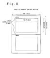
Fig. 8 is a diagram when a decoded data and a correlation signal are transferred in a time division multiplexing manner in the scanning system converting apparatus according to a second embodiment of the present invention; -
Fig. 9 is a block diagram illustrating the structure of the scanning system converting apparatus according to the second embodiment of the present invention; and -
Fig. 10 is a diagram illustrating the relation of frame period and vertical axis in the image data of the interlace scanning system. - Description of the Preferred Embodiments Next, the scanning system converting apparatus of the present invention will be described with reference to the attached drawings.
-
Fig. 3 is a block diagram which shows the structure of the scanning system converting apparatus according to the first embodiment of this embodiment. As illustrated, the image output system is composed of an MPEG2 decoder 1, anNTSC encoder 2, a scanningsystem converting circuit 3, atransfer control section 4 and agraphic system 5. The scanningsystem converting circuit 3 is composed of afield memory 3a, an averagevalue interpolating section 3b, aline memory 3c, amotion detecting section 3d, a fieldcorrelation determining section 3e, a timingsignal generating section 3f, aswitch 3g,FIFO memories switch 3j. - The MPEG2 decoder 1 decodes an MPEG2 coded image data which has been coded in accordance with the MPEG2 and which is supplied through a communication line. Then, the MPEG2 decoder 1 outputs the decoded image data in the field frequency of the NTSC video signal of the (2:1) interlace scanning system. Also, the MPEG2 decoder 1 outputs a sync signal of the NTSC video signal.
- The MPEG2 coded image data which is supplied to the MPEG2 decoder 1 is obtained by coding an image data of the interlace scanning system or an image data of the progressive scanning system. Therefore, in order to distinguish the scanning system of the image data, a signal, Progressive_sequence, is provided in a sequence extension of a sequence header in the MPEG2 coded image data. This signal is "1" when the image data of the progressive scanning system is coded into the MPEG2 coded image data, and is "0" when the image data of the interlace scanning system is coded.
- Also, the image data of the progressive scanning system includes the image data of a movie film. The frame rate of the image data is 24 Hz and is different from 30 Hz of NTSC. For the purpose of the conversion of the frame rate, in the MPEG2 coded image data, a signal, repeat_first_field, is provided in the picture coding extension of the image header. When this signal is "1", the frame is repeatedly outputted so that the frame rate can be converted.
- The MPEG2 decoder 1 can recognize a field having correlation in accordance with these two kinds of signals, and generates and supplies a 2-bit field correlation signal to the field
correlation determining section 3e. The field correlation signal has the following meaning to each value. That is, - "00": indicates that the data is obtained by decoding the MPEG2 coded image data which has been obtained by coding an image data of the interlace scanning system and the field correlation is invalid;
- "01": indicates that the field is the first field of one frame of the image data obtained by decoding the MPEG2 coded image data which has been obtained by coding an image data of progressive scanning system and that the field correlation is effective;
- "10": indicates that the field is the next field of one frame of the image data obtained by decoding the MPEG2 coded image data which has been obtained by coding an image data of progressive scanning system and that the field correlation is effective; and
- "11": indicates that the field is repeated based on a signal repeat_first_field and that the field correlation is effective.
- The
NTSC encoder 2 generates an NTSC video signal based on the decoded image data and the sync signal which are outputted from the MPEG2 decoder 1. The generated NTSC video signal is supplied to an NTSC TV monitor (not shown) so that a corresponding image is displayed on the NTSC TV monitor. - The scanning
system converting circuit 3 converts the decoded image data which is outputted in the interlace scanning system from the MPEG2 decoder 1, into the progressive scanning system and supplies it to thetransfer control section 4. Hereinafter, the structure of the scanningsystem converting circuit 3 will be described in detail. - The
field memory 3a delays the decoded image data which is outputted from the MPEG2 decoder 1 and whose original image data is of the interlace scanning system, for one field timing and outputs to themotion detecting section 3d and theswitch 3g. - The
line memory 3c delays the decoded image data which is outputted from MPEG2 decoder 1, for one line timing of the NTSC interlace scanning system and outputs to the averagevalue interpolating section 3b. It should be noted that in the effective image data in this embodiment, 1 line is composed of 720 pixels, 1 field is composed of 240 lines and 1 frame is composed of 2 fields, i.e., 480 lines. - The average
value interpolating section 3b calculates an average value of a twice previous field of the image data which is outputted from the MPEG2 decoder 1 and a current field of the image data which is outputted from theline memory 3c for every pixel, and outputs the average value to themotion detecting section 3d and theswitch 3g. - The
motion detecting section 3d operates in accordance with an instruction from the fieldcorrelation determining section 3e. When the fieldcorrelation determining section 3e determines that the field correlation is effective, i.e., that the original image data is of the progressive scanning system, themotion detecting section 3d issues an instruction to theswitch 3g such that theswitch 3g selects the image data outputted from thefield memory 3a. When the fieldcorrelation determining section 3e determines that the field correlation is invalid, i.e., that the original image data is of the interlace scanning system, themotion detecting section 3d determines whether a difference between the image data which is outputted from thefield memory 3a and the image data which is outputted from the averagevalue interpolating section 3b is equal to or larger than a predetermined value. Themotion detecting section 3d issues an instruction to theswitch 3g such that theswitch 3g selects the image data outputted from the averagevalue interpolating section 3b, when the difference is equal to or larger than the predetermined value, and such that theswitch 3g selects the image data outputted from thefield memory 3a when the difference is smaller than the predetermined value. - The field
correlation determining section 3e determines the field correlation signal outputted from the MPEG2 decoder 1. The fieldcorrelation determining section 3e issues an instruction to themotion detecting section 3d such that theswitch 3g always outputs the image data which is outputted from thefield memory 3a, when the field correlation is effective (when the field correlation signal is "01", "10" or "11"). Also, the fieldcorrelation determining section 3e issues an instruction to the timingsignal generating section 3f such that thetransfer control section 4 transfers, to thegraphic system 5, only an effective portion of the image data which has been converted into the progressive scanning system, e.g., only the effective portion of the first one of fields of the frame of the image data. When the field correlation is invalid (when the field correlation signal is "00"), the fieldcorrelation determining section 3e does not issue any instruction to themotion detecting section 3d. Also, the fieldcorrelation determining section 3e issues an instruction to the timingsignal generating section 3f such that the timingsignal generating section 3f outputs an instruction to thetransfer control section 4 so that thetransfer control section 4 transfers all of the image data which has been converted into the progressive scanning system, to the graphic system. That is, the instruction is effective for the effective portion of each field of the frame of the image data. - The timing
signal generating section 3f sends a timing signal to theswitch 3j in accordance with the determining result by the fieldcorrelation determining section 3e and the sync signal which is outputted from the MPEG2 decoder 1 such that theswitch 3j is always switched for every line. - The
switch 3j alternately selects and outputs one of the image data which is outputted from theFIFO memory 3h and the image data which is outputted from theFIFO memory 3i based on this timing signal. Also, the timingsignal generating section 3f sends to the transfer control section 4a a timing signal (hereinafter, to be referred to as an effective signal) indicating that the image data which is outputted from theswitch 3j is effective, when the timing signal is in the high level. - The
switch 3g selects and outputs one of the image data which is outputted from thefield memory 3a and the image data which is outputted from the averagevalue interpolating section 3b for every line or every pixel in accordance with the instruction from themotion detecting section 3d. - Each of the
FIFO memories field memory 3a and the output signal of the averagevalue interpolating section 3b which is selectively outputted by the switching of theswitch 3g is written in theFIFO memory 3h. The decoded image data which is outputted from the MPEG2 decoder 1 is written in theFIFO memory 3i. - The
transfer control section 4 has a buffer memory which stores the image data outputted from theswitch 3j temporarily. Also, thetransfer control section 4 supplies the effective portion of the image data which has been stored in the buffer memory to thegraphic system 5 at the frame rate of 60 frames per one second, based on the signal which indicates the effective portion which is supplied from the timingsignal generating section 3f. - The
graphic system 5 has a frame memory for storing the effective portion of the image data which has been transferred from thetransfer control section 4. Also, thegraphic system 5 displays an image on the monitor in the progressive scanning system. In this case, the graphic system displays the image data which is transferred from thetransfer control section 4. However, when no image data is transferred from thetransfer control section 4, thegraphic system 5 displays the previous field or frame of the image data. - Next, an operation of the scanning system converting apparatus in the first embodiment of the present will be described.
- In the scanning system converting apparatus of this embodiment, an operation in the case where the decoded image data is converted by the scanning
system converting circuit 3 will be described. The operation of scanningsystem converting circuit 3 is different depending upon whether the MPEG2 coded image data is obtained by coding the image data of the progressive scanning system or by coding from the image data of the interlace scanning system. Hereinafter, an operation in each case will be described. - The MPEG2 decoder 1 receives the MPEG2 coded image data having Progressive_Sequence of "1". Therefore, the MPEG2 decoder 1 decodes the received MPEG2 coded image data to sequentially output as the image data of the interlace scanning system. At the same time, the MPEG2 decoder 1 supplies a sync signal to the timing
signal generating section 3f, and supplies, to the fieldcorrelation determining section 3e, the field correlation signal which takes either of "01", "10" or "11" value in accordance with the field. - An instruction is sent from the field
correlation determining section 3e to themotion detecting section 3d in response to such a value of the field correlation signal with such that theswitch 3g selects the image data outputted from thefield memory 3a. By this, the operation of themotion detecting section 3d is stopped and theswitch 3g is switched to always output the image data which has been outputted from thefield memory 3a. - Paying attention to the image data which has been outputted from the MPEG2 decoder 1, the image data which is outputted from the
field memory 3a is delayed for one field time from the image data which has been outputted from the MPEG2 decoder 1. That is, when the image data for the first field of one frame is outputted from thefield memory 3a and is written in theFIFO memory 3h, the image data for the following field is outputted from the MPEG2 decoder 1 and is written in theFIFO memory 3i. - On the other hand, the timing signal to switch the
switch 3j is supplied from the timingsignal generating section 3f based on the sync signal which has been supplied from the MPEG2 decoder 1. In response to this timing signal, theswitch 3j is switched in response to the timing signal such that the image data outputted from theFIFO memory 3h and the image data outputted from theFIFO memory 3i are alternately outputted for every line. By this, the image data which is outputted from theswitch 3j is the image data of the progressive scanning system having no skip of any line. The image data of this progressive scanning system is supplied to thetransfer control section 4 and is temporarily stored in a buffer memory of thetransfer control section 4. - Also, in the field
correlation determining section 3e, when it is determined that the field correlation signal value is "10", an instruction is sent to the timingsignal generating section 3f so as to send an effective indication signal with the high level to thetransfer control section 4. As shown inFigs. 4A and 4B , based on this instruction, the effective indication signal with the high level is sent from the timingsignal generating section 3f to thetransfer control section 4. Thetransfer control section 4 transfers the effective portion of the image data which is stored newly in the buffer memory to thegraphic system 5. Thus, the image data which has been transferred from thetransfer control section 4 is displayed on the monitor of thegraphic system 5. - On the other hand, in the field
correlation determining section 3e, when it is determined that the field correlation signal value is "01" or "11", an instruction is not sent to the timingsignal generating section 3f. Therefore, as shown inFigs. 4A and 4B , the effective indication signal which is sent from the timingsignal generating section 3f to thetransfer control section 4 becomes the low level, so that thetransfer control section 4 does not transfer image data to thegraphic system 5. As a result, in thegraphic system 5, the image data which has been transferred last is displayed, i.e., the same image is repetitively displayed. - The timings from the decoding of the MPEG2 coded image data to the display which are described above are shown in
Fig. 5 , taking as an example the case that the image data before coding is the movie film which has the frame rate of 24 Hz. In this example, image data of the progressive scanning system is obtained from one field of the movie film with the frame rate of 24 Hz through the scanning system conversion. The image data is supplied to thegraphic system 5 with the frame rate 75 Hz. Therefore, the same image data is repetitively displayed to eliminate the frame rate difference. - The MPEG2 decoder 1 receives the MPEG2 coded image data with Progressive_Sequence of "1". At that time, the MPEG2 decoder 1 decodes the received MPEG2 coded image data to sequentially output in the interlace scanning system. Also, the MPEG2 decoder 1 supplies the sync signal to the timing
signal generating section 3f, and supplies the field correlation signal of the value of "00" to the fieldcorrelation determining section 3e. - From the
line memory 3c, the image data which has been outputted from the MPEG2 decoder 1 is delayed for one line time and outputted to the averagevalue interpolating section 3b. An average of the image data which is outputted from theline memory 3c and the image data which is outputted from the MPEG2 decoder 1 is calculated by the averagevalue interpolating section 3b, and a signal is generated which interpolates the line which is skipped in the interlace scanning system. - On the other hand, since the field correlation signal is "00" in this case, an instruction is sent from the field
correlation determining section 3e to themotion detecting section 3d. At this time, themotion detecting section 3d compares the image data which is outputted from thefield memory 3a and the image data which is outputted from the averagevalue interpolating section 3b, in response to the instruction. As to the comparing result, when it is determined that a difference between both of the image data is smaller than a predetermined value, that is, when it is determined that there is no movement between images, themotion detecting section 3d outputs an instruction to theswitch 3g. As a result, theswitch 3g is switched in response to the instruction from themotion detecting section 3d in such a manner that the image data outputted from thefield memory 3a is selected. When it is determined that the difference between both of the image data is larger than the predetermined value, that is, when it is determined that there is movement in the image, themotion detecting section 3d outputs an instruction to theswitch 3g. Theswitch 3g is switched in response to the instruction from themotion detecting section 3d in such a manner that the average of the image data outputted from the averagevalue interpolating section 3b is selected. Thus, the selected image data is written in theFIFO memory 3h. - In this case, the writing of the image data which is outputted from the MPEG2 decoder 1 in the
FIFO memory 3i, the generation of the timing signal by the timingsignal generating section 3f, the switching by theswitch 3j, the writing of the image data which is outputted from theswitch 3j into the buffer memory of thetransfer control section 4 are the same as those in the case that the image data before coding is the image data of the progressive scanning system. - Also, when it is determined in the field
correlation determining section 3e that the field correlation signal value is "00", an instruction is sent to the timingsignal generating section 3f such that the effective indication signal with the high level is sent to thetransfer control section 4. As shown inFigs. 6A and 6B , based on this instruction, the effective indication signal with the high level is sent from the timingsignal generating section 3f to thetransfer control section 4. Thetransfer control section 4 transfers to thegraphic system 5, the effective portion of the image data which is stored newly in the buffer memory therein. Then, the image data which is transferred from thetransfer control section 4 is displayed on the monitor of thegraphic system 5. - The timings from the decoding of the MPEG2 coded image data to the display on the graphic system which are described above are shown in
Fig. 7 , taking as an example the case that the image data before coding is the NTSC video signal which has the frame rate of 30 Hz. In this example, each field of each frame of the image data of the progressive scanning system after the scanning system conversion is transferred to thegraphic system 5. However, for the difference between the frame rates, the same image are repetitively displayed sometimes to cancel the difference. - As described above, in the scanning system converting apparatus of this embodiment, when the MPEG2 coded image data is obtained by coding the image data of the progressive scanning system, any interpolation signal is never used for the purpose of the conversion into the progressive scanning system. Therefore, the image data which is outputted from the
switch 3j and which is converted into the progressive scanning system is substantively the same as the image data before coding, so that the image quality is not degraded. Moreover, the image data of the progressive scanning system which is outputted from theswitch 3j is the same as the image data before coding in the frame rate, and a data amount of the image data which is transferred from thetransfer control section 4 is a few. - Also, because the image data which is outputted from the MPEG2 decoder 1 is of the NTSC interlace scanning system, the image data is possible to be displayed on the NTSC TV monitor and on the monitor of the graphic system through the scanning
system converting circuit 3 and thetransfer control section 4. - Also, when the image data before coding is of the interlace scanning system, any problem never occurs in the conversion into the progressive scanning system, because the interpolation signal can be used.
- In above-mentioned embodiment, the MPEG2 decoder 1 outputs the image data of the NTSC 2:1 interlace scanning system. However, it is possible to output the image data in another interlace scanning system, e.g., n:1 (n is an integer equal to or more than 3) interlace scanning system. In this case, it is sufficient that a plurality of field memories which have the delayed field times different from each other are provided and the FIFO memories which correspond to the plurality of field memories are provided. Also, the average
value interpolating section 3b is sufficient to calculate an average weighted in accordance with the vertical distance determined in order of the fields. - In the above-mentioned embodiment, the decoded data and the field correlation signal are outputted onto the different signal lines from the MPEG2 decoder 1. However, as shown in the schematic diagram of
Fig. 10 and the block diagram ofFig. 9 , they may be outputted on the identical signal line in a time division multiplexing manner. - In above-mentioned embodiment, the image data which is coded in accordance with MPEG2 is described as the example. However, the present invention is not limited to this. The present invention is possible to be applied to all cases in which when the image data of the interlace scanning system or of the progressive scanning system has been coded by a coding system other than MPEG2 and is decoded and outputted in the interlace scanning system, the image data is converted into the progressive scanning system.
- As described above, according to the present invention, when the image data before coding is of the image of the progressive scanning system, the image data after the scan conversion is substantively the same as the image data before coding so that the image quality is not degraded.
Claims (6)
- A scanning system converting system for a display unit of a progressive scanning system comprising:a) decoding means (1) for decoding coded first image data into decoded first image data in an interlace scanning system and for outputting control data, wherein said coded first image data is obtained by coding image data of an interlace or a progressive scanning system, and said control data indicates whether the scanning system of said coded first image data is the progressive scanning system or the interlace scanning system and whether fields of said first image data are correlated;b) control means (3e, 3f) for generating an effective indication signal and first and second control signals based on said control data supplied from said decoder; andc) field memory means (3a) for storing a current field of said decoded first image data outputted from said decoding means (1) and for outputting with a delay of one field time a previous field of said decoded image data for every line as first line image data;d) first line memory means (3c) for storing a current line of a current field of said decoded first image data outputted from said decoding means (1) for every line and for outputting the stored previous line of said current field for every line as second line image data;e) interpolating means (3b) for generating interpolated image data for every line from said current line of said current field and said second line image data outputted from said first line memory means (3c) to output third line image data;f) first switching means (3g) for selecting one of said first line image data and said third line image data in response to a first switching signal to output the selected image data as fourth line image data;g) detecting means (3d) for detecting a difference between said first line image data and said third line image data to output said first switching signal to said first switching means (3g) in response to said first control signal and based on the detecting result, wherein, when said first image data is of a progressive scanning system, said first switching signal causes said first switching means (3g) in response to said first control signal to select said first line image data, and wherein, when said first image data is of an interlace scanning system, said first switching signal causes said first switching means (3g) based on the detecting result in response to said first control signal to select said first line image data when said difference is smaller than a predetermined value, and otherwise to select said third line image data;h) second line memory means (3h) for storing said fourth line image data and for outputting the stored previous line of said fourth line image data as fifth line image data;i) third line memory means (3i) for storing said current line of said current field outputted from said decoding means (1) for every line and for outputting the stored previous line of said current field as sixth line image data;andj) second switching means (3j) for alternatingly selecting one of said fifth line image data and said sixth line image data in response to said second control signal as a second switching signal to output the selected image data as said output image data;k) transfer means (4), comprising a buffer for intermediately storing said output image data, for transferring said output image data from said buffer to said display unit in response to an active state of said effective indication signal; andl) wherein said control means (3e, 3f) outputs said effective indication signal such that said effective indication signal is active when said first image data is of the interlace scanning system, and such that said effective indication signal is active only for the first one of the fields of a frame of said output image data being received by said buffer from said second switching means when said first image data is of the progressive scanning system.
- A scanning system converting system according to claim 1, wherein said coded image data is obtained by coding said first image data based on a MPEG2, and said decoding means (1) decodes said coded image data based on the MPEG2.
- A method of converting a scanning system (3) of an image data signal into a progressive scanning system of a display unit, comprising the steps of:a) decoding coded first image data into decoded first image data in an interlace scanning system and outputting control data, wherein said coded first image data is obtained by coding image data of an interlace or a progressive scanning system, and said control data indicates whether the scanning system of said coded first image data is the progressive scanning system or the interlace scanning system and whether fields of said first image data are correlated;b) generating an effective indication signal and first and second control signals based on said control data;c) storing a current field of said decoded first image data and outputting with a delay of one field time a previous field of said decoded image data for every line as first line image data;d) storing a current line of a current field of said decoded first image data outputted for every line and outputting the stored previous line of said current field for every line as second line image data;e) generating interpolated image data for every line from said current line of said current field and said second line image data (3c) to output third line image data;f) selecting (3g) one of said first line image data and said third line image data in response to a first switching signal to output the selected image data as fourth line image data;g) detecting (3d) a difference between said first line image data and said third line image data to output said first switching signal in response to said first control signal and based on the detecting result, wherein, when said first image data is of a progressive scanning system, said first switching signal causes in response to said first control signal selecting said first line image data, and wherein, when said first image data is of an interlace scanning system, said first switching signal causes based on the detecting result in response to said first control signal selecting said first line image data when said difference is smaller than a predetermined value, and otherwise selecting said third line image data;h) storing said fourth line image data and outputting the stored previous line of said fourth line image data as fifth line image data;i) storing said current line of said current field outputted from said decoding for every line and outputting the stored previous line of said current field as sixth line image data; andj) alternatingly selecting one of said fifth line image data and said sixth line image data in response to said second control signal as a second switching signal to output the selected image data as said output image data;k) intermediately storing said output image data, and transferring said intermediately stored output image data to said display unit in response to an active state of said effective indication signal; andl) wherein said generating of said effective indication signal is such that said effective indication signal is active when said first image data is of the interlace scanning system, and such that said effective indication signal is active only for the first one of the fields of a frame of said output image data being received for said intermediately storing when said first image data is of the progressive scanning system.
- A method according to claim 3, wherein said original image data is obtained by coding an image data based on a MPEG2, and said decoding step includes decoding said coded image data based on the MPEG2.
- A method according to claim 3, further comprising the step of selectively inhibiting said output of said sixth line image data when said original image data is of the progressive scanning system.
- A method according to claim 5, wherein said selectively inhibiting step includes selectively inhibiting said output of said sixth line image data such that said sixth line image data for one of fields of the frame is outputted and such that said fifth line image data for the other fields of the frame is not outputted.
Applications Claiming Priority (3)
| Application Number | Priority Date | Filing Date | Title |
|---|---|---|---|
| JP32159797A JP3360586B2 (en) | 1997-11-21 | 1997-11-21 | Scan conversion apparatus and method |
| JP32159797 | 1997-11-21 | ||
| JP321597/97 | 1997-11-21 |
Publications (3)
| Publication Number | Publication Date |
|---|---|
| EP0918436A2 EP0918436A2 (en) | 1999-05-26 |
| EP0918436A3 EP0918436A3 (en) | 2000-04-12 |
| EP0918436B1 true EP0918436B1 (en) | 2012-01-11 |
Family
ID=18134326
Family Applications (1)
| Application Number | Title | Priority Date | Filing Date |
|---|---|---|---|
| EP19980121030 Expired - Lifetime EP0918436B1 (en) | 1997-11-21 | 1998-11-05 | Conversion of decoded interlaced video into progressive scanning system taking account of scanning system before coding |
Country Status (3)
| Country | Link |
|---|---|
| US (1) | US6072531A (en) |
| EP (1) | EP0918436B1 (en) |
| JP (1) | JP3360586B2 (en) |
Families Citing this family (28)
| Publication number | Priority date | Publication date | Assignee | Title |
|---|---|---|---|---|
| WO1999004569A1 (en) * | 1997-07-15 | 1999-01-28 | Matsushita Electric Industrial Co., Ltd. | Progressive image signal transmitter, progressive image signal receiver and, medium |
| KR100297776B1 (en) * | 1998-06-23 | 2001-10-26 | 윤종용 | 3D signal processing device using motion information in video signal decoding |
| JP4158232B2 (en) * | 1998-07-23 | 2008-10-01 | ソニー株式会社 | Image information conversion device and image display device |
| US6407775B1 (en) * | 1999-04-16 | 2002-06-18 | Avid Technology, Inc. | Image resizer and frame rate converter with pulldown controller |
| EP1243141B1 (en) * | 1999-12-14 | 2011-10-19 | Scientific-Atlanta, LLC | System and method for adaptive decoding of a video signal with coordinated resource allocation |
| US6940911B2 (en) * | 2000-03-14 | 2005-09-06 | Victor Company Of Japan, Ltd. | Variable picture rate coding/decoding method and apparatus |
| US6414719B1 (en) * | 2000-05-26 | 2002-07-02 | Sarnoff Corporation | Motion adaptive median filter for interlace to progressive scan conversion |
| US7098957B2 (en) * | 2000-12-20 | 2006-08-29 | Samsung Electronics Co., Ltd. | Method and apparatus for detecting repetitive motion in an interlaced video sequence apparatus for processing interlaced video signals |
| US7110612B1 (en) | 2001-10-11 | 2006-09-19 | Pixelworks, Inc. | Weighted absolute difference based noise reduction method and apparatus |
| JP3596521B2 (en) * | 2001-12-13 | 2004-12-02 | ソニー株式会社 | Image signal processing apparatus and method |
| JP3596520B2 (en) * | 2001-12-13 | 2004-12-02 | ソニー株式会社 | Image signal processing apparatus and method |
| US7274857B2 (en) | 2001-12-31 | 2007-09-25 | Scientific-Atlanta, Inc. | Trick modes for compressed video streams |
| JP2003228920A (en) * | 2002-01-31 | 2003-08-15 | Toshiba Corp | Information storage medium for storing program array information, information recording device, and information reproducing device |
| US7154556B1 (en) * | 2002-03-21 | 2006-12-26 | Pixelworks, Inc. | Weighted absolute difference based deinterlace method and apparatus |
| KR100971859B1 (en) | 2002-09-23 | 2010-07-22 | 실리콘 이미지, 인크.(델라웨어주 법인) | Detection and repair of mpeg-2 chroma upconversion artifacts |
| KR100563866B1 (en) * | 2003-05-19 | 2006-03-23 | 매크로영상기술(주) | Apparatus and method for deinterlace of video signal |
| TWI222831B (en) * | 2003-07-09 | 2004-10-21 | Mediatek Inc | Video playback system to generate both progressive and interlace video signals |
| US7966642B2 (en) * | 2003-09-15 | 2011-06-21 | Nair Ajith N | Resource-adaptive management of video storage |
| GB2411305A (en) * | 2004-02-19 | 2005-08-24 | Tandberg Television Ltd | Selecting between a de-interlaced signal and a delayed progressive signal dependent on the type of input signal detected |
| US8600217B2 (en) * | 2004-07-14 | 2013-12-03 | Arturo A. Rodriguez | System and method for improving quality of displayed picture during trick modes |
| US7542095B2 (en) * | 2005-01-20 | 2009-06-02 | Samsung Electronics Co., Ltd. | Method and system of noise-adaptive motion detection in an interlaced video sequence |
| US20090033791A1 (en) * | 2007-07-31 | 2009-02-05 | Scientific-Atlanta, Inc. | Video processing systems and methods |
| JP4751413B2 (en) * | 2008-04-08 | 2011-08-17 | 株式会社東芝 | Information processing apparatus and determination mode setting method for decoder |
| US8300696B2 (en) | 2008-07-25 | 2012-10-30 | Cisco Technology, Inc. | Transcoding for systems operating under plural video coding specifications |
| JP5238850B2 (en) * | 2011-05-18 | 2013-07-17 | 株式会社東芝 | Information processing apparatus and moving picture stream decoding method |
| EP3301922B1 (en) | 2011-06-15 | 2023-08-02 | Panasonic Intellectual Property Corporation of America | Video encoding device and video encoding method |
| CN103609116A (en) | 2011-06-17 | 2014-02-26 | 松下电器产业株式会社 | Video decoding device and video decoding method |
| US9998750B2 (en) | 2013-03-15 | 2018-06-12 | Cisco Technology, Inc. | Systems and methods for guided conversion of video from a first to a second compression format |
Citations (4)
| Publication number | Priority date | Publication date | Assignee | Title |
|---|---|---|---|---|
| US5365273A (en) * | 1992-04-24 | 1994-11-15 | Deutsche Thomson-Brandt Gmbh | Method and device for film-mode detection |
| EP0710018A2 (en) * | 1994-10-31 | 1996-05-01 | Victor Company Of Japan, Ltd. | Scanning line interpolating apparatus with a motion vector detector |
| EP0757482A2 (en) * | 1995-07-31 | 1997-02-05 | Hewlett-Packard Company | An edge-based interlaced to progressive video conversion system |
| JPH09182032A (en) * | 1995-12-22 | 1997-07-11 | Hitachi Ltd | Video signal processor |
Family Cites Families (10)
| Publication number | Priority date | Publication date | Assignee | Title |
|---|---|---|---|---|
| JPH0479685A (en) * | 1990-07-23 | 1992-03-13 | Toshiba Corp | Tv signal transmitter |
| JP3531186B2 (en) * | 1992-09-18 | 2004-05-24 | ソニー株式会社 | Video signal encoding method and apparatus |
| US5444491A (en) * | 1993-02-26 | 1995-08-22 | Massachusetts Institute Of Technology | Television system with multiple transmission formats |
| JP3617088B2 (en) * | 1994-10-20 | 2005-02-02 | 株式会社日立製作所 | Television receiver |
| KR960020415A (en) * | 1994-11-23 | 1996-06-17 | 윌리엄 이. 힐러 | Special features for digital television |
| KR960028124A (en) * | 1994-12-30 | 1996-07-22 | 이몬 제이. 월 | Method and apparatus for identifying video fields generated by film sources |
| US5610661A (en) * | 1995-05-19 | 1997-03-11 | Thomson Multimedia S.A. | Automatic image scanning format converter with seamless switching |
| JP2861902B2 (en) * | 1995-12-27 | 1999-02-24 | 日本電気株式会社 | Video signal processing method and apparatus |
| US5754248A (en) * | 1996-04-15 | 1998-05-19 | Faroudja; Yves C. | Universal video disc record and playback employing motion signals for high quality playback of non-film sources |
| JP3698189B2 (en) * | 1997-11-12 | 2005-09-21 | 株式会社岡村製作所 | Seismic isolation device for furniture on casters |
-
1997
- 1997-11-21 JP JP32159797A patent/JP3360586B2/en not_active Expired - Fee Related
-
1998
- 1998-11-04 US US09/185,710 patent/US6072531A/en not_active Expired - Lifetime
- 1998-11-05 EP EP19980121030 patent/EP0918436B1/en not_active Expired - Lifetime
Patent Citations (4)
| Publication number | Priority date | Publication date | Assignee | Title |
|---|---|---|---|---|
| US5365273A (en) * | 1992-04-24 | 1994-11-15 | Deutsche Thomson-Brandt Gmbh | Method and device for film-mode detection |
| EP0710018A2 (en) * | 1994-10-31 | 1996-05-01 | Victor Company Of Japan, Ltd. | Scanning line interpolating apparatus with a motion vector detector |
| EP0757482A2 (en) * | 1995-07-31 | 1997-02-05 | Hewlett-Packard Company | An edge-based interlaced to progressive video conversion system |
| JPH09182032A (en) * | 1995-12-22 | 1997-07-11 | Hitachi Ltd | Video signal processor |
Also Published As
| Publication number | Publication date |
|---|---|
| JP3360586B2 (en) | 2002-12-24 |
| EP0918436A3 (en) | 2000-04-12 |
| JPH11155132A (en) | 1999-06-08 |
| US6072531A (en) | 2000-06-06 |
| EP0918436A2 (en) | 1999-05-26 |
Similar Documents
| Publication | Publication Date | Title |
|---|---|---|
| EP0918436B1 (en) | Conversion of decoded interlaced video into progressive scanning system taking account of scanning system before coding | |
| CN100469101C (en) | Adaptive display controller | |
| EP0743788B1 (en) | Automatic image scanning format converter with seamless switching | |
| KR100426890B1 (en) | A video scan format converter suitable for high-definition television systems | |
| EP1011267B1 (en) | Receiver for simultaneously displaying signals having different display formats and/or different frame rates and method thereof | |
| EP0637889A2 (en) | Device for converting image frame format | |
| JPH0795852B2 (en) | Coding device for television signals | |
| KR20060047630A (en) | Block mode adaptive motion compensation | |
| EP0933942B1 (en) | Progressive image signal transmitter, progressive image signal receiver and, medium | |
| JPH0422075B2 (en) | ||
| JP2000500318A (en) | Adaptive image delay device | |
| US7295245B2 (en) | Method and apparatus for converting frame rate using time shifting and motion compensation | |
| JPS61118085A (en) | Coding system and device for picture signal | |
| US5801777A (en) | Device and method for decoding digital video data | |
| US7092444B2 (en) | Image signal decoder for determining interframe motion | |
| US7239353B2 (en) | Image format conversion apparatus and method | |
| EP1592246A1 (en) | Film mode determination in video image still areas | |
| US7012648B2 (en) | Image conversion method and image conversion apparatus | |
| US20040017510A1 (en) | Video signal processing apparatus | |
| WO2000011612A1 (en) | Methods and apparatus for reducing the amount of buffer memory required for decoding mpeg data and for performing scan conversion | |
| EP1592249B1 (en) | Reverse film mode extrapolation | |
| KR100385975B1 (en) | Apparatus for converting video format and method thereof | |
| KR100311009B1 (en) | Apparatus and method for converting video format using common format | |
| US6542197B1 (en) | Three-dimensional signal processor using motion information upon decoding image signal | |
| US20040263688A1 (en) | Television receiver and control method thereof |
Legal Events
| Date | Code | Title | Description |
|---|---|---|---|
| PUAI | Public reference made under article 153(3) epc to a published international application that has entered the european phase |
Free format text: ORIGINAL CODE: 0009012 |
|
| AK | Designated contracting states |
Kind code of ref document: A2 Designated state(s): DE GB NL |
|
| AX | Request for extension of the european patent |
Free format text: AL;LT;LV;MK;RO;SI |
|
| PUAL | Search report despatched |
Free format text: ORIGINAL CODE: 0009013 |
|
| AK | Designated contracting states |
Kind code of ref document: A3 Designated state(s): AT BE CH CY DE DK ES FI FR GB GR IE IT LI LU MC NL PT SE |
|
| AX | Request for extension of the european patent |
Free format text: AL;LT;LV;MK;RO;SI |
|
| 17P | Request for examination filed |
Effective date: 20000302 |
|
| AKX | Designation fees paid |
Free format text: DE GB NL |
|
| 17Q | First examination report despatched |
Effective date: 20040903 |
|
| RAP1 | Party data changed (applicant data changed or rights of an application transferred) |
Owner name: ACER INCORPORATED |
|
| REG | Reference to a national code |
Ref country code: DE Ref legal event code: R079 Ref document number: 69842561 Country of ref document: DE Free format text: PREVIOUS MAIN CLASS: H04N0005440000 Ipc: H04N0007010000 |
|
| RIC1 | Information provided on ipc code assigned before grant |
Ipc: H04N 7/01 20060101AFI20110418BHEP |
|
| RTI1 | Title (correction) |
Free format text: CONVERSION OF DECODED INTERLACED VIDEO INTO PROGRESSIVE SCANNING SYSTEM TAKING ACCOUNT OF SCANNING SYSTEM BEFORE CODING |
|
| GRAP | Despatch of communication of intention to grant a patent |
Free format text: ORIGINAL CODE: EPIDOSNIGR1 |
|
| RIN1 | Information on inventor provided before grant (corrected) |
Inventor name: SHIBANO, MOTOYOSHI |
|
| GRAS | Grant fee paid |
Free format text: ORIGINAL CODE: EPIDOSNIGR3 |
|
| GRAA | (expected) grant |
Free format text: ORIGINAL CODE: 0009210 |
|
| AK | Designated contracting states |
Kind code of ref document: B1 Designated state(s): DE GB NL |
|
| REG | Reference to a national code |
Ref country code: GB Ref legal event code: FG4D |
|
| REG | Reference to a national code |
Ref country code: DE Ref legal event code: R096 Ref document number: 69842561 Country of ref document: DE Effective date: 20120315 |
|
| REG | Reference to a national code |
Ref country code: NL Ref legal event code: T3 |
|
| PLBE | No opposition filed within time limit |
Free format text: ORIGINAL CODE: 0009261 |
|
| STAA | Information on the status of an ep patent application or granted ep patent |
Free format text: STATUS: NO OPPOSITION FILED WITHIN TIME LIMIT |
|
| 26N | No opposition filed |
Effective date: 20121012 |
|
| REG | Reference to a national code |
Ref country code: DE Ref legal event code: R097 Ref document number: 69842561 Country of ref document: DE Effective date: 20121012 |
|
| PGFP | Annual fee paid to national office [announced via postgrant information from national office to epo] |
Ref country code: DE Payment date: 20171031 Year of fee payment: 20 |
|
| PGFP | Annual fee paid to national office [announced via postgrant information from national office to epo] |
Ref country code: NL Payment date: 20171016 Year of fee payment: 20 Ref country code: GB Payment date: 20171101 Year of fee payment: 20 |
|
| REG | Reference to a national code |
Ref country code: DE Ref legal event code: R071 Ref document number: 69842561 Country of ref document: DE |
|
| REG | Reference to a national code |
Ref country code: NL Ref legal event code: MK Effective date: 20181104 |
|
| REG | Reference to a national code |
Ref country code: GB Ref legal event code: PE20 Expiry date: 20181104 |
|
| PG25 | Lapsed in a contracting state [announced via postgrant information from national office to epo] |
Ref country code: GB Free format text: LAPSE BECAUSE OF EXPIRATION OF PROTECTION Effective date: 20181104 |