EP0918302B1 - Coherence detector - Google Patents
Coherence detector Download PDFInfo
- Publication number
- EP0918302B1 EP0918302B1 EP98122061A EP98122061A EP0918302B1 EP 0918302 B1 EP0918302 B1 EP 0918302B1 EP 98122061 A EP98122061 A EP 98122061A EP 98122061 A EP98122061 A EP 98122061A EP 0918302 B1 EP0918302 B1 EP 0918302B1
- Authority
- EP
- European Patent Office
- Prior art keywords
- disparity
- image
- image data
- supplied
- values
- Prior art date
- Legal status (The legal status is an assumption and is not a legal conclusion. Google has not performed a legal analysis and makes no representation as to the accuracy of the status listed.)
- Expired - Lifetime
Links
Images


Classifications
-
- G—PHYSICS
- G06—COMPUTING; CALCULATING OR COUNTING
- G06T—IMAGE DATA PROCESSING OR GENERATION, IN GENERAL
- G06T7/00—Image analysis
- G06T7/50—Depth or shape recovery
- G06T7/55—Depth or shape recovery from multiple images
- G06T7/593—Depth or shape recovery from multiple images from stereo images
-
- G—PHYSICS
- G06—COMPUTING; CALCULATING OR COUNTING
- G06T—IMAGE DATA PROCESSING OR GENERATION, IN GENERAL
- G06T2200/00—Indexing scheme for image data processing or generation, in general
- G06T2200/28—Indexing scheme for image data processing or generation, in general involving image processing hardware
-
- G—PHYSICS
- G06—COMPUTING; CALCULATING OR COUNTING
- G06T—IMAGE DATA PROCESSING OR GENERATION, IN GENERAL
- G06T2207/00—Indexing scheme for image analysis or image enhancement
- G06T2207/10—Image acquisition modality
- G06T2207/10004—Still image; Photographic image
- G06T2207/10012—Stereo images
-
- H—ELECTRICITY
- H04—ELECTRIC COMMUNICATION TECHNIQUE
- H04N—PICTORIAL COMMUNICATION, e.g. TELEVISION
- H04N13/00—Stereoscopic video systems; Multi-view video systems; Details thereof
- H04N13/20—Image signal generators
- H04N13/204—Image signal generators using stereoscopic image cameras
- H04N13/239—Image signal generators using stereoscopic image cameras using two 2D image sensors having a relative position equal to or related to the interocular distance
-
- H—ELECTRICITY
- H04—ELECTRIC COMMUNICATION TECHNIQUE
- H04N—PICTORIAL COMMUNICATION, e.g. TELEVISION
- H04N13/00—Stereoscopic video systems; Multi-view video systems; Details thereof
- H04N2013/0074—Stereoscopic image analysis
- H04N2013/0081—Depth or disparity estimation from stereoscopic image signals
Definitions
- the present invention relates to a coherence detector for use in an image processing device, especially in a stereoscopic device Image processing.
- the optical detection of the three-dimensional environment wins has become increasingly important for some time.
- the robots used must have two-dimensional coordinates also depth information regarding a (to be processed) Object are available, for example to be able to control a robot accordingly.
- Previously known implementations for determining depth information can be divided into different groups, which are based on different procedures.
- Triangulation methods use one or more lines, either from a laser or a projection unit are mapped to the object in question. With a or several cameras, the object is then under a slightly different from the projection direction, another point of view. Based on the known Geometric relationships then take place using trigonometric calculations to determine the three-dimensional Structure of the object.
- the respective The object to be illuminated is to be illuminated. This does under Laboratory conditions are not a problem, but will be in practice almost impossible when in situations such as traffic or under difficult existing with telescopes or microscopes real-world measurements. Furthermore, lasers used as line light projectors to observe special accident prevention regulations, so with such test setups no danger for human eye exists.
- runtime methods evaluate the runtime of light, Microwaves or a sound signal as a measurement signal out to draw conclusions about the spatial environment and the To draw depth information.
- a spatial direction targeted and made a distance measurement.
- Runtime procedures require a complex Signal processing and are also of the properties of the surrounding medium depending on the propagation properties of the measurement signal concerned.
- Depth of field methods are also used, the however can only be applied if the object size and opening a lens in a particular one Are related to each other, such as in microscopy. In doing so, only the narrow area of the focal plane sharp on an image sensor displayed. The areas in front and behind are more or less unfocused.
- the one contained in the focal plane Image information can be processed using conventional image processing techniques be evaluated. A corresponding evaluation then returns a contour of the object. By multiple Moving the focal plane and subsequent evaluation then a contour map of the object can be created, however, which is correspondingly complex.
- the phenomenon of spatial vision which is briefly described below in Relation to humans is generally based on the perception of the visible environment by means of the two human eyes, the due to the eye relief two perceived images (right eye or image, left Eye or image) from slightly different angles be perceived. Because the visual axes of the eyes are something converge, their visual axes meet at one Point of the environment under consideration, being from a fixation this point is spoken through the eyes. The picture this point falls on a visual pit of the retina. Each neighboring point in the visual field will then open up a location of the retina that projects somewhat from the center from the sharpest vision. Generally is this distance is different in both eyes, with the Distance as a function of the spatial depth of the considered Point in the visual field varies relative to the fixation point. These distance deviations are called binocular disparities referred to below as "disparities" are designated.
- the real problem with stereo viewing is besides that Evaluation of the given trigonometric conditions in figuring out which pixel the real one World or of the object seen in the first of the stereoscopic Images occurs, which pixel in the second corresponds to the stereoscopic images.
- disparities For spatial vision or 3D stereo perception it then becomes necessary from the disparities to the three-dimensional Close the structure of the perceived image.
- from identified disparities can refer to the depth information contained in the perceived image getting closed.
- Stereo processes endeavor to match corresponding pixels between a first (left) and a second (right) Find stereo image, then from the relative shift such pixels with a known camera position the distance of the points can be calculated.
- stereo methods distinguish between so-called feature-based Stereo method, intensity based stereo method and phase-based stereo process.
- the correspondence search is carried out certain characteristics (e.g. edges or intensity maxima) extracted from the image data for more stable than the raw image intensities are kept.
- characteristics e.g. edges or intensity maxima
- Such Procedures are stable if there are few stable features (such as object edges) are extracted. You are too fast because images are only processed at the locations on which characteristics were recorded. this leads to a noticeable data reduction.
- Intensity-based stereo processes work directly with the supplied by the stereo cameras or image recorders Image brightness. Therefore, they are related to each other to use very stable algorithms of appropriate brightness, which require a corresponding amount of computing time. Under The intensity-based process can be further differentiated are between correlation based methods and Dynamic programming method.
- the former strive to have a small image area of the left Picture in the right picture. This is usually done Procedure to maximize correlation or Minimizing the difference used. If the image sections large enough, you can achieve them Process stable and dense disparity cards, one Real time processing using special complex Hardware is conceivable.
- the raw disparity cards included typically, however, only shifts in the area of accuracy of a picture element (pixel) so that the resolution is limited. Only by using interpolation methods or else iterative methods can increase the accuracy of the Disparities improved to sub-pixel accurate disparities become.
- Such correlation-based methods are, for example in the publication DE 34 25 946 A1 and the article "A stereovision system for a planetary rover: calibration, correlation, registration, and fusion "by Z. Zhang, in: Machine Vision and Applications, No. 10, 1997, pp.27-34.
- intensity-based Procedure a dense disparity map (a disparity value for almost every pixel), the minimization the measure of error as in the method of minimizing the Difference, however, is time consuming and therefore not for Real-time applications is suitable. Reducing the required Computing time can be increased by using hierarchical Procedures can be reduced, but only through use complicated and not parallelizable algorithmic Structures for which a hardware solution is at least extreme becomes complex and therefore costly.
- Phase-based stereo processes are also an issue current investigations. These procedures extract from a local Fourier phase (usually through Filtering using Gabor functions), and then try either, these Fourier phase images (for the right or left picture) (e.g. described by Weng) in agreement or by using Fourier's shift theorem to calculate the local shift (e.g. described by Sanger, Fleet & Jepson).
- the extraction effectively corresponds to the local Fourier phase a local contrast compensation, which makes many through Variations in brightness caused errors in other stereo processes be reduced.
- These phase-based stereo processes work with sub-pixel accuracy and are also for real-time applications implementable. However, for generation hierarchical procedures are used are usually special for avoiding errors Catch exceptional situations (see Fleet). This makes the algorithms used complicated and one Hardware implementation complex and costly.
- this object is achieved as defined in claim 1,
- the object is further achieved by an image processing device with shifting devices for mutual Shift of these respectively supplied image data a first picture and one to this under another Angle taken second image, the Image data in parallel on the shifting devices be tapped and in pairs a subsequent disparity detection device be fed; being the Disparity detection device for each of the supplied Image data pairs using a respective disparity element a spatial depth information for each Determining the disparity value representing the image data pair, and the determined disparity values of a coherence detection device feeds, where the output disparity value determined for each shift of the image data and the associated spatial depth information represents.
- the feeds Image signals are processed at the speed as they are supplied by image recorders. So that is Image data processing for obtaining depth information possible with little effort and in real time.
- This high processing speed (real time) of the system is a significant advantage over the state of the Technology.
- a frame rate of, for example, 25 frames per second fed to the system by the image sensor and are processed by it in real time is the system or the method implemented with it the arrangements known from the prior art or Procedure at least by a speed factor of 100 think.
- the volume of the object to be measured is opposite known systems no longer limited.
- the measuring range of the image processing device according to the invention only by limiting the imaging used Optics determined, and all optical attachments such as microscopes, telephoto or wide-angle lenses can in Connection with the image sensors can be used, provided they are adapted to them.
- the device according to the invention also does not apply pretreatment of the test object itself, for example covering the test object with light powder for removal of reflections and highlights on the object surface before measuring and removing the powder after Measurement. By saving such operations the device according to the invention works in time and cost-effective.
- the device according to the invention is not limited to the area of visible light, but for example, the evaluation can also be carried out for image signals Infrared range.
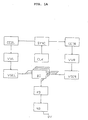
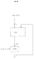
- FIG. 1A shows the stereoscopic image processing device according to the invention for capturing three-dimensional Diagram objects in real time as a block diagram.
- the image processing device has a sensor head which comprises two image recorders, one image pickup CCDL for the (first) left image and an image sensor CCDR for the (second) right picture.
- One of these pictures will thereby for the subsequent processing as a reference image Are defined. That is, determined disparity results to create a disparity map the image data of the reference image be assigned.
- the image recorders can be, for example Acting camera pair with CCD imagers in one predetermined known distance d from each other are and therefore slightly different images of the same Take object (see. Fig. 1B and Fig. 6).
- the image recorders can record moving images and these feed the device for subsequent real time processing.
- SYNC will be the recordings of the image pickup devices CCDL, CCDR synchronized in time, so that left and right picture taken synchronously to each other become.
- a disparity detector DD Device and one as a disparity coherence detector KD designated facility (both below are described in detail) may be actual Disparities or shifts are determined and then through trigonometric calculations taking into account the known distance d between the image recorders CCDL, CCDR calculates the spatial distance of the respective object are thus obtained the depth information sought become.
- the depth information calculated in this way from two stereo moving images can be practically instantaneous in real time as a video signal output and as a third dimension (e.g. third image) is shown as a grayscale image or color image become.
- the real-time processing of the system is particularly important through the serial processing the through the Image sensor CCDL, CCDR conditionally delivered image data.
- a clock generator CLK Connected to the image sensor synchronization device SYNC is a clock generator CLK, the clock signals for Control and synchronization of other system components generated.
- the recorded image signals are used by the image recorders CCDL, CCDR assigned to these preprocessing devices VVL, VVR supplied.
- VVL preprocessing facilities
- VVR there is a brightness compensation of the two stereo images before subsequent processing.
- This brightness preprocessing is advantageous because slightly different image recording angle of the image sensor CCDL, CCDR so-called highlights and reflections on (reflective) surfaces of the recorded objects can occur in the subsequent processing the image data to record the disparities to errors can lead, so that the disparity values become unstable could.
- color images can be in the frame the preprocessing by the preprocessing facilities a breakdown of the respective (first and second) Color image data in respective color image components (e.g. in the primary colors red, green, blue (RGB) or in Luminance and the two color difference components). It is also possible to use the first and second To subject image data to different preprocessing.
- first and second To subject image data can be used to different preprocessing.
- the image data are preprocessing devices VVL, VVR of the first and second (or left and right) picture respectively Devices VSEL, VSER for mutual displacement the left and right image data in relation to each other fed. More precisely, this means that two displacement devices each VSEL, VSER form a displacement unit, whereby each with a shift current of image data "Right" and "Left” per shifting unit.
- a displacement unit is for to provide any kind of image data. That is, in the case of one Preprocessing by splitting into the primary colors R, G and B three displacement units can be provided, and one for each primary color.
- the disparities of image data shifted relative to one another in this way are then for respective image data pairs by the disparity detector DD determined and a respective set received Disparity values for the image data pairs are determined by the Disparity coherence detector KD evaluated.
- This coherence detection with regard to the disparities obtained is based on the selection or determination of that of obtained disparity values, which are approximately identical to at least one other of the disparity values obtained is.
- the disparity value becomes that actual or true disparity value determined in approximately identical to at least one other disparity value (i.e. in a predetermined interval around this) or identical to at least one other disparity value is.
- Fig. 5 illustrates this principle using data from, for example seven disparity elements of a disparity detector.
- disparity coherence detector KD determines whether actual disparity values are then from this to a facility NB for post-processing image data output.
- This device NB prepares the disparity values so that this via an output connector DV one optionally connectable output device such as Example of a display device (not shown) can be and from this as a gray value or Color image can be reproduced.
- the disparity values are carried out as part of the image data postprocessing also eliminating edge effects that occur as well as a virtual limit.
- An external control unit is not shown in the figure itself to configure the system by a Workstation computer with a suitable interface to the system can be implemented.
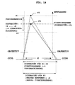
- FIG. 1B schematically shows the principle of a stereoscopic Image capture.
- CCDL CCDR they are all in one
- the distance d is the distance between the optical axes of the lenses defined as vertical running dash-dotted lines are drawn.
- the Point P2 is further in the direction of the optical axis removed as the point P1.
- the point P1 lies in one reference plane defined as the fixation plane for which a (relative) disparity of zero is assumed. Different expressed, is the determined disparity at the fixation level based.
- a suitable advance e.g. y1, or y2
- the first and second image data can thus be the fixation plane determined and the basic measuring range can be determined.
- the fixation level in an interval of disparity values [-x ..., 0, ..., + x] surrounds the so-called fusion area.
- the fusion range corresponds to a "depth of field".
- the (relative) disparity values in the fusion area are due to the shifting devices VSEL, VSER additional contingent shift of the image data determined. The greater the additional shift is evaluated, the larger the Fusion area and thus the "depth of field" around the Fixation level.
- the additionally achievable shift stands both in connection with the number n of displacement elements of the displacement devices described below, as well as the way of controlling them.
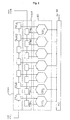
- the image data shifting device VSEL for image data of the (first) left image
- the image data shifter VSER for Image data of the (second) right image, which together form one Form shift unit
- the disparity detector DD as a disparity determining device.
- the components 2 does not refer to a specific implementation fixed in analog or digital technology and their description is initially general, independent from the actual form of realization.
- VVL, VVR output image data are the image data shifters VSEL, VSER fed. This supply takes place as mentioned above, with a pre-shift according to the desired basic measuring range. In the shown There is only one case to simplify the illustration Shift unit for one type of image data, for example shown for one of the primary colors R, G, B.
- the picture elements are shifted against each other.
- the evaluation of the picture elements with regard to the existing disparity is then carried out in pairs. More precisely, the disparity is evaluated in pairs based on the shifted image data for pairs ( ⁇ X L1 , ⁇ X Rn ), ( ⁇ X L2, ⁇ X Rn-1 ), ..., ( ⁇ X Ln-1, ⁇ X R2 ), ( ⁇ X Ln , ⁇ X R1 ).
- the amount ⁇ X of the shift can be set to a value corresponding to the length of a picture element.
- this shift can, however, also be set to a value that is smaller than the length of a picture element, for example half the length of a picture element (pixel).
- this requires a higher number of elements of the disparity detector described below if the fusion area is to remain constant.
- VSEL In the case of shifting devices implemented as an analog circuit VSEL, VSER each consist of a chain or cascade of delay elements (delay elements) with appropriate signal taps.
- the shift amount in the x-direction then corresponds to the runtime and can be picture element by picture or selected in fractions of picture elements his.
- VSER In the case of shifting devices implemented as digital circuits VSEL, VSER consists of the respective unit shift registers connected in series, to which a corresponding Clock signal from the clock generator CLK (if necessary. via an intermediate frequency divider (not shown) is to be fed. But then it is necessary the analog image data using an analog / digital converter convert into digital image data. On such analog / digital converter can be before or after respective preprocessing device VVL, VVR in the signal curve be provided depending on whether the preprocessing still analog or digital.
- the shifting elements ⁇ X Li , ⁇ X Ri of the respective shifting device for shifting by picture elements are carried out in accordance with the clock with which the digital image data are supplied.
- the already digitized data must be fed to a special filter. For example, a shift corresponding to half a picture element is achieved by averaging two successive picture elements by means of a corresponding filter and taking the value obtained as the signal value of the picture element at the position shifted by half a picture element. Such filtering then essentially corresponds to dithering of neighboring picture elements.
- the control can be used for both displacement devices VSEL, VSER take place simultaneously, or alternatively in phase opposition take place, depending on which additional shift range ("Depth of field”) is desired.
- controls are shifts by -7, -5, -3, ..., +5 as well as -6, -4-, -2, ...., +6 possible. Because of the larger additional shift is included an extended depth of field is to be expected.
- the evaluation can be gradient-based, tensor-based, energy-based or according to Reichard's diffraction detection model.
- These evaluation principles are adequately described in the specialist literature (e.g. Barron, Fleet & Jepson, Adelson & Berger DJ Fleet and AD Jepson, Stability of Phase Information, IEEE Trans. Patt. Anal. Mach. Intel. 15, 1253- 1268, 1993 JL Barron, DJ Fleet and SS Beauchemin, Performance of Optical Flow Techniques, Int. J. Comp. Vis. 12, 43-77, 1994 EH Adelson and JR Bergen, Spatiotemporal Energy Models for the Perception of Motion, J. Opt. Soc. Am. A 2, 284-299, 1985. 15) and it will not be discussed in detail here.
- the disparity values output by the disparity elements EST i (1 i i n n) are subsequently fed to the coherence detector KD, which determines the actual disparity value from the supplied values.
- the coherence detector KD determines the actual disparity value from the supplied values.
- all outputs of the respective disparity detectors are fed to a subsequent coherence detector KD.
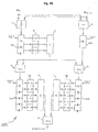
- 3A now shows in detail a functional circuit diagram of a disparity element EST i , in which the evaluation is based on the gradient-based approach.
- Image data ⁇ X Li , ⁇ X Rn + 1-i (1 i i n n) are supplied to the respective disparity element EST i . These are then fed to a unit performing a pixel-by-pixel (pixel-by-pixel) addition (reference symbol "+”), then to a multiplication unit designated by the reference symbol "1/2", which carries out a multiplication of the added pixel values by a factor of 1/2, so that averaging takes place with respect to the pair of image data supplied in each case.
- the image data processed in this way then pass through a derivative filter DIFF.
- a simple derivative filter DIFF can have filter coefficients, for example, as are given in Table 1 below.
- the data values output by this filter are subjected, on the one hand, to pixel-by-pixel squaring in a unit denoted by the reference symbol “x 2 ”, the values obtained in this way then being fed to an averaging filter AVE.
- the data output by the filter DIFF are fed to a multiplication unit (reference symbol "*"), where they are multiplied pixel by pixel by the difference of the data ⁇ X Li , ⁇ X Rn + 1-i obtained pixel by pixel by means of a subtraction unit (reference symbol "-").
- the values obtained in this way which are available at the output of the multiplication unit, are likewise fed to a further averaging filter AVE.
- filter coefficients can be selected, such as those found in B. are shown in the following Table 2.
- the data values obtained at the outputs of both averaging filters are finally fed to a division unit (reference symbol “+”), which outputs the respectively determined disparity value at its output as the output signal of the respective disparity element EST i .
- the disparity values determined in this way which are output at the outputs of the disparity elements EST i , are then fed to the disparity coherence detector KD.
- FIG. 3B shows a block diagram for the hardware implementation of an individual disparity element EST i , which was described functionally above with reference to FIG. 3A.
- a disparity element EST consists of shift registers SR1 to SR4 clocked from the clock generator CLK and clocked for the synchronization of the entire circuit for temporary storage of individual picture elements, as well as arithmetic logic circuits (mean value generator 1: " ⁇ / 2", subtractor 2: “-”, Multiplication devices 4, 5: MUL, summers 3, 6, 7: " ⁇ ", division device 8: DIV).
- the filter designated DIFF in FIG. 3A is now implemented by the shift register SR1, a coefficient multiplication part K (K1, K2, K3) and the summer 3.
- FIG. 4A shows a block diagram for a coherence detector or disparity coherence detector KD according to a first Embodiment, a coherence detector as an example KD is shown with only four inputs.
- a coherence detector as an example KD is shown with only four inputs.
- the circuit shown in FIG. 2 would have to be corresponding expanded to seven inputs or generally to n inputs become. If several (z) displacement units with respectively assigned disparity detectors DD with n EST each Elements would be provided, the switching would be to z * n inputs to expand.
- the data values of the ascertained disparities supplied by the (not shown) EST elements EST i and applied to the inputs E1 to E4 are fed to a sorting device S1, which outputs the data values sorted at the outputs A to D according to the size of the values. In the case shown, output A has the smallest value, output D has the largest value.
- sorting devices can be implemented with logic gates consisting of comparators (comparators) and multiplexers and are not explained in detail here.
- Each of the outputs A to D is fed to a multiplexer MUX1, while two of the outputs are each fed to a subtractor ("-") in order to determine the differences BA, CB and DC of the corresponding values.
- the differences are fed to a further sorting device S2 which, in accordance with the first device S1, outputs the values of the differences sorted at the output at the output.
- a further sorting device S2 which, in accordance with the first device S1, outputs the values of the differences sorted at the output at the output.
- only the smallest result (at the " ⁇ " output) is to be processed further, which represents the pair of values of the disparities that are "most adjacent" to one another, that is to say have the smallest deviation from one another.
- This variant represents the simpler variant in terms of circuitry, because this would also be ascertainable from the internal decision states of the sorter S2.
- the result obtained by the device checking for equality in turn serves to control the multiplexer MUX1 in order to supply the two output signals of the sorter S1 belonging to the difference to an averager (reference symbol " ⁇ / 2"), which adds the two values for determining the mean value and then by two divided.
- This mean value then represents the result KE, that is to say the coherence value of the large number of disparity values determined.
- a variant of the circuit described above exists therein, the differences determined with a threshold to compare, with only the candidates or values to be processed below the certain Threshold, or within a threshold certain window value range (e.g. according to the Fusion area).
- a downstream rear derailleur finds the largest cluster of neighboring candidates. Both variants are possible and can be related to the respective one Use case the better results deliver.
- FIG. 4B shows an embodiment variant of the previously described Coherence detector KD, in which the coherence detector in addition to output signals of the EST elements, further data is supplied become.
- This can be used in particular if receive the image data interlaced or "interlaced" and all the image information of one Full screen e.g. composed of two fields. Then are the disparity values for image data one Field determined and the corresponding coherence value of Disparities determined for pixels of a field. For a respective field becomes the KE values for the pixels of the field in a memory device MEM (with a storage capacity for one field), and read out during the next field period and the coherence detector KD on an additionally to be provided Input connector supplied.
- MEM memory device
- the internal structure of the coherence detector KD is essentially identical to that in Connection described with Fig. 4A, with the difference that he can process an additional (the feedback) signal must be able to do what different variants are possible are.
- the feedback coherence disparity value are already fed to the sorter S1 and be taken into account there, or later at influence the averaging. In the latter case it would be it to the averager (reference symbol " ⁇ / 2").
- the circuit shown in FIG. 4A is then corresponding in each case to modify.
- the present n disparity values by means of the coherence detector selected in each case KD according to the first or second embodiment in Processed or compared in real time, and that disparity value output as the actual disparity value, which is almost identical to as many others as possible supplied disparity values. More precisely, that means that as many disparity values as possible in an interval of z. B. about 0.2 to 0.4 around the disparity value in question should lie around so that this disparity value in question is the actual disparity value. The easiest it is when there are multiple disparity values for a particular picture element have the same value. This case corresponds in the graphic representation according to FIG. 5 an intersection of at least two of the n disparity values for a particular one Pixel.
- the line-by-line analysis of the n disparity values for each picture element of a relevant line then provides, for example, a course of the actual Disparity for a relevant line of the image as in the right part of Fig. 5 is shown, from the total a disparity map of the analyzed image lines determined or represented in the form of a third image can be (upper picture on the right in Fig. 5).
- disparity elements EST can guarantee the accuracy or reliability of the true disparity determined by the coherence detector be increased because there are more disparity values, which are evaluated for their coherence.
- each disparity element EST calculates the disparity in the entire measuring range, i.e. completely parallel. therefore the many known from the prior art are omitted Realizations necessary iterative approximation of rough ones towards fine measuring ranges, around the actual disparity value to investigate.
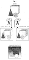
- FIG. 6 shows a further example of image recorders CCDL, CCDR captured images "left image” (a) and "right picture” (b) of objects arranged in space.
- Both pictures have a first and a second object in front of another (third) object, which is in the background the spatial scene shown can be seen.
- Sensor system for processing stereoscopic images in A disparity card (c) is then obtained in real time as a gray scale image (or as a color image) on a screen can be represented.
- an object in the foreground is highlighted, an object in the middle depth range a light to dark gray value corresponding to the depth shown, and the object in the background as the object with the greatest depth is approximate in the disparity map reproduced in black.
- the one in the given example 6 described form of representation for the depth information is not mandatory, however. As well objects in the foreground may appear dark, and objects in the background are bright.
- the data can display the disparity card can also be used for control purposes by this data is used, for example, to control robots during assembly processes and a target-actual comparison with predefined 3-D manufacturing data and the depth information determined from the disparities.
- Unmanned vehicles can reach and / or fall below a predetermined minimum depth value for prevention of collisions through appropriate controls to be evaded, this principle also when implementing passive and / or active distance warning and anti-collision systems can be used in motor vehicles is.
- Show other possible uses for the system in medical technology for example in three-dimensional Scanning body contours for the classification of Dysplasias.
Description
Die vorliegende Erfindung betrifft einem Kohärenzdetektor zur Verwendung in einer Bildverarbeitungsvorrichtung, insbesondere in einer Vorrichtung zur stereoskopischen Bildverarbeitung.The present invention relates to a coherence detector for use in an image processing device, especially in a stereoscopic device Image processing.
Aus Henkel R D : "Fast stereovision by coherence detection", 7th Intern. Conf. Computer Analysis of Images and Patterns, CAIP 97, pp. 297-304, 1997, Springer Verlay, ISBN 3-540-63460-6 ist bekannt wie ein repräsentativer Disparitätswert mittels Kohärenzdetektion basierend auf einer Menge von potentiellen Kandidaten ermittelt wird, indem nahe beeinander liegende Eingangssignalwerte ( di ≈ dj) ausgewählt werden und anschließend ein Mittelwert der ausgewählten Signalwerte ausgegeben wird (d ≈ < di > i ε C ).From Henkel RD: "Fast stereovision by coherence detection", 7 th intern. Conf. Computer Analysis of Images and Patterns, CAIP 97, pp. 297-304, 1997, Springer Verlay, ISBN 3-540-63460-6 it is known how a representative disparity value is determined by means of coherence detection based on a set of potential candidates, by selecting closely adjacent input signal values (d i ≈ d j ) and an average of the selected signal values is then output (d ≈ <d i > i ε C).
Die optische Erfassung der dreidimensionalen Umgebung gewinnt seit geraumer Zeit zunehmend an Bedeutung. Insbesondere bei automatisierten Fertigungsabläufen und den dabei eingesetzten Robotern müssen neben zweidimensionalen Koordinaten auch Tiefeninformationen hinsichtlich eines (zu bearbeitenden) Objektes zur Verfügung stehen, um beispielsweise einen Roboter entsprechend steuern zu können.The optical detection of the three-dimensional environment wins has become increasingly important for some time. In particular with automated production processes and the same The robots used must have two-dimensional coordinates also depth information regarding a (to be processed) Object are available, for example to be able to control a robot accordingly.
Im Rahmen der "Ident Vision" Messe 1996 in Stuttgart (DE) wurde zum Beispiel ein Ganzkörperscanner vorgestellt, der mittels einer Vielzahl von Lasern und Kameras die räumliche Kontur eines Objekts erfassen kann. Jedoch ist dieses System für Echtzeit-Anwendungen ungeeignet.As part of the "Ident Vision" fair 1996 in Stuttgart (DE) For example, a full-body scanner was presented, the using a variety of lasers and cameras the spatial Can capture the contour of an object. However, this system is unsuitable for real-time applications.
Bislang bekannte Realisierungen zur Ermittlung von Tiefeninformationen kann man in verschiedene Gruppen unterteilen, die auf jeweils verschiedenen Verfahren beruhen.Previously known implementations for determining depth information can be divided into different groups, which are based on different procedures.
Triangulationsverfahren verwenden eine oder mehrere Linien, die entweder von einem Laser oder einer Projektionseinheit auf das betreffende Objekt abgebildet werden. Mit einer oder mehreren Kameras wird das Objekt anschließend unter einem von der Projektionsrichtung geringfügig abweichenden, anderen Blickwinkel aufgenommen. Beruhend auf den vorbekannten geometrischen Verhältnissen erfolgt dann mittels trigonometrischer Berechnungen die Ermittlung der dreidimensionalen Struktur des Objektes.Triangulation methods use one or more lines, either from a laser or a projection unit are mapped to the object in question. With a or several cameras, the object is then under a slightly different from the projection direction, another point of view. Based on the known Geometric relationships then take place using trigonometric calculations to determine the three-dimensional Structure of the object.
Nachteilig bei diesen Verfahren ist jedoch, daß unter Umständen für jede projizierte Linie ein Bild auszuwerten ist, was äußerst zeitaufwendig ist, so daß ein derartiges System nicht echtzeittauglich ist.A disadvantage of these methods, however, is that under certain circumstances evaluate an image for each projected line is what is extremely time consuming, so such System is not real-time capable.
Darüber hinaus ist es insbesondere nachteilig, daß das jeweilige Meßobjekt zu beleuchten ist. Dies stellt zwar unter Laborbedingungen kein Problem dar, wird aber in der Praxis fast unmöglich, wenn in Situationen wie im Straßenverkehr oder unter bei Teleskopen oder Mikroskopen vorliegenden erschwerten realen Situationen Messungen durchzuführen sind. Ferner sind bei als Linienlichtprojektoren verwendeten Lasern spezielle Unfallverhütungsvorschriften zu beachten, damit bei derartigen Meßaufbauten keine Gefahr für das menschliche Auge besteht.In addition, it is particularly disadvantageous that the respective The object to be illuminated is to be illuminated. This does under Laboratory conditions are not a problem, but will be in practice almost impossible when in situations such as traffic or under difficult existing with telescopes or microscopes real-world measurements. Furthermore, lasers used as line light projectors to observe special accident prevention regulations, so with such test setups no danger for human eye exists.
Bei einem speziellen Triangulationsverfahren wird ein Farbfächer auf das betreffende Objekt projiziert. Die von einer Kamera aufgenommenen Farbwerte können dann eindeutig einem Objektpunkt zugeordnet werden, wobei die Verschiebung einzelner Farbpunkte wiederum als Tiefeninformation auswertbar ist. Obwohl dieses Verfahren in Echtzeit arbeitet, bringt dieses Verfahren die einschränkende Forderung mit sich, daß das Objekt und der Hintergrund weiß sein müssen, so daß das Verfahren nicht universell einsetzbar ist. In a special triangulation process, a color fan is created projected onto the object in question. The one Color values recorded by the camera can then be clearly assigned to one Object point can be assigned, the shift individual Color points in turn can be evaluated as depth information is. Although this method works in real time, it brings this procedure involves the restrictive requirement that the object and the background must be white so that the The method is not universally applicable.
Dagegen werten Laufzeitverfahren die Laufzeit von Licht, Mikrowellen oder eines Schallsignals als einem Meßsignal aus, um Rückschlüsse auf die räumliche Umgebung und die Tiefeninformation zu ziehen. Dabei wird jeweils eine Raumrichtung angepeilt und eine Abstandsmessung vorgenommen. Beispielsweise beruhen das Prinzip eines Radargerätes oder eines medizinischen Ultraschallgerätes auf derartigen Laufzeitverfahren. Laufzeitverfahren erfordern jedoch eine aufwendige Signalverarbeitung und sind zudem von den Eigenschaften des umgebenden Mediums abhängig, das die Ausbreitungseigenschaften des betreffenden Meßsignals beeinflußt.In contrast, runtime methods evaluate the runtime of light, Microwaves or a sound signal as a measurement signal out to draw conclusions about the spatial environment and the To draw depth information. Each time there is a spatial direction targeted and made a distance measurement. For example, the principle of a radar device or a medical ultrasound device on such runtime methods. Runtime procedures, however, require a complex Signal processing and are also of the properties of the surrounding medium depending on the propagation properties of the measurement signal concerned.
Weiterhin kommen Schärfentiefeverfahren zum Einsatz, die jedoch nur dann angewendet werden können, wenn die Objektgröße und die Öffnung eines Objektivs in einem bestimmten Verhältnis zueinander stehen, wie beispielsweise in der Mikroskopie. Dabei wird durch das optische System nur der schmale Bereich der Fokalebene scharf auf einen Bildsensor abgebildet. Die Bereiche davor und dahinter sind mehr oder weniger unfokussiert. Die in der Fokalebene enthaltene Bildinformation kann mit herkömmlichen Bildverarbeitungsverfahren ausgewertet werden. Eine entsprechende Auswertung liefert dann eine Höhenlinie des Objekts. Durch mehrfaches Verschieben der Fokalebene und anschließender Auswertung kann dann eine Höhenlinienkarte des Objekts erstellt werden, was jedoch entsprechend aufwendig ist.Depth of field methods are also used, the however can only be applied if the object size and opening a lens in a particular one Are related to each other, such as in microscopy. In doing so, only the narrow area of the focal plane sharp on an image sensor displayed. The areas in front and behind are more or less unfocused. The one contained in the focal plane Image information can be processed using conventional image processing techniques be evaluated. A corresponding evaluation then returns a contour of the object. By multiple Moving the focal plane and subsequent evaluation then a contour map of the object can be created, however, which is correspondingly complex.
Ein weiterer Ansatz, der erst seit wenigen Jahren verfolgt wird, beruht in der Auswertung stereoskopischer Bilder zum Gewinnen von Tiefeninformationen, ähnlich dem räumlichen Sehen beim Menschen, dessen Nachbildung durch derartige Verfahren angestrebt ist.Another approach that has only been pursued for a few years is based on the evaluation of stereoscopic images for Obtaining depth information similar to the spatial one Seeing in humans, their replication through such Process is sought.
Das Phänomen des räumlichen Sehens, das nachfolgend kurz in Bezug auf den Menschen allgemein erläutert ist, beruht auf der Wahrnehmung der sichtbaren Umwelt mittels der beiden menschlichen Augen, wobei aufgrund des Augenabstandes die beiden wahrgenommenen Bilder (rechtes Auge bzw. Bild, linkes Auge bzw. Bild) unter leicht unterschiedlichen Blickwinkeln wahrgenommen werden. Da die Sehachsen der Augen etwas konvergieren, treffen sich ihre Sehachsen an einem Punkt der betrachteten Umwelt, wobei von einer Fixierung dieses Punktes durch die Augen gesprochen wird. Das Bild dieses Punktes fällt jeweils auf eine Sehgrube der Netzhaut. Jeder benachbarte Punkt im Gesichtsfeld wird dann auf eine Stelle der Netzhaut projiziert, die etwas vom Zentrum des schärfsten Sehens entfernt liegt. Im allgemeinen ist dieser Abstand in beiden Augen unterschiedlich, wobei der Abstand als Funktion der räumlichen Tiefe des betrachteten Punktes im Gesichtsfeld relativ zum Fixationspunkt variiert. Diese Abstandsabweichungen werden als binokulare Disparitäten bezeichnet, die nachfolgend kurz als "Disparitäten" bezeichnet sind.The phenomenon of spatial vision, which is briefly described below in Relation to humans is generally based on the perception of the visible environment by means of the two human eyes, the due to the eye relief two perceived images (right eye or image, left Eye or image) from slightly different angles be perceived. Because the visual axes of the eyes are something converge, their visual axes meet at one Point of the environment under consideration, being from a fixation this point is spoken through the eyes. The picture this point falls on a visual pit of the retina. Each neighboring point in the visual field will then open up a location of the retina that projects somewhat from the center from the sharpest vision. Generally is this distance is different in both eyes, with the Distance as a function of the spatial depth of the considered Point in the visual field varies relative to the fixation point. These distance deviations are called binocular disparities referred to below as "disparities" are designated.
Beim Stereosehen besteht das eigentliche Problem, neben der Auswertung der jeweils gegebenen trigonometrischen Gegebenheiten darin herauszufinden, welcher Bildpunkt der realen Welt bzw. des gesehenen Objekts, der im ersten der stereoskopischen Bilder auftritt, welchem Bildpunkt im zweiten der stereoskopischen Bilder entspricht. Anders ausgedrückt, gilt es in Bezug auf das menschliche Auge herauszufinden, welcher Bildpunkt auf der linken Netzhaut welchem Bildpunkt auf der rechten Netzhaut entspricht.The real problem with stereo viewing is besides that Evaluation of the given trigonometric conditions in figuring out which pixel the real one World or of the object seen in the first of the stereoscopic Images occurs, which pixel in the second corresponds to the stereoscopic images. Expressed differently, it is important to find out in relation to the human eye which pixel on the left retina which pixel on the right retina.
Für das räumliche Sehen bzw. die 3D-Stereowahrnehmung ist es dann erforderlich, aus den Disparitäten auf die dreidimensionale Struktur des wahrgenommenen Bildes zurück zuschließen. Anders ausgedrückt, aus ermittelten Disparitäten kann auf die in dem wahrgenommenen Bild enthaltenen Tiefeninformationen geschlossen werden.For spatial vision or 3D stereo perception it then becomes necessary from the disparities to the three-dimensional Close the structure of the perceived image. In other words, from identified disparities can refer to the depth information contained in the perceived image getting closed.
Bislang verfügbare Stereoverfahren sind jedoch auf leistungsfähige Arbeitsplatzrechner (PC's bzw. sogenannte "Workstations") angewiesen, wobei zur Ermittlung der gewünschten Tiefeninformationen aus einem einzigen Stereobildpaar, beispielsweise unter Verwendung eines handelsüblichen Arbeitsplatzrechners (mit einer Taktfrequenz von etwa 90 MHz), eine Zeit im Bereich von etwa 3 bis 5 Minuten erforderlich ist.However, stereo methods currently available are based on powerful ones Workstation computers (PCs or so-called "Workstations") instructed to determine the desired Depth information from a single stereo image pair, for example using a commercially available Workstation computer (with a clock frequency of about 90 MHz), a time in the range of about 3 to 5 minutes is required.
Versucht man jedoch, derartige Verfahren in spezielle Rechenwerke auszulagern, übersteigt der Entwicklungs- und Hardwareaufwand sehr schnell wirtschaftlich vertretbare Grenzen. Die Markteinführung derartiger Systeme scheiterte bislang also entweder an einer zu geringen Verarbeitungsgeschwindigkeit oder einem zu hohen Systempreis.However, attempts are made to use such methods in special arithmetic units outsource, the development and Hardware expenditure very quickly economically justifiable Limits. The market launch of such systems failed So far either because the processing speed is too slow or a system price that is too high.
Stereoverfahren sind bestrebt, einander entsprechende Bildpunkte zwischen einem ersten (linken) und zweiten (rechten) Stereobild zu finden, wobei dann aus der relativen Verschiebung solcher Bildpunkte bei bekannter Kameraposition die Entfernung der Punkte berechnet werden kann. Stereo processes endeavor to match corresponding pixels between a first (left) and a second (right) Find stereo image, then from the relative shift such pixels with a known camera position the distance of the points can be calculated.
Unter den vorstehend angesprochenen herkömmlichen rechnerimplementierbaren Stereoverfahren kann man im wesentlichen unterscheiden zwischen sogenannten merkmalsbasierten Stereoverfahren, intensitätsbasierten Stereoverfahren und phasenbasierten Stereoverfahren.Among the conventional computer implementable mentioned above One can essentially use stereo methods distinguish between so-called feature-based Stereo method, intensity based stereo method and phase-based stereo process.
Bei merkmalsbasierten Stereoverfahren werden vor der Korrespondenz-Suche bestimmte Merkmale (z.B. Kanten oder Intensitätsmaxima) aus den Bilddaten extrahiert, die für stabiler als die rohen Bildintensitäten gehalten werden. Derartige Verfahren sind stabil, falls nur wenige stabile Merkmale (etwa Objektkanten) extrahiert werden. Sie sind auch schnell, da Bilder nur an den Orten weiterverarbeitet werden müssen, an denen Merkmale erfaßt wurden. Dies führt zu einer merklichen Datenreduktion.In the case of feature-based stereo procedures, the correspondence search is carried out certain characteristics (e.g. edges or intensity maxima) extracted from the image data for more stable than the raw image intensities are kept. such Procedures are stable if there are few stable features (such as object edges) are extracted. You are too fast because images are only processed at the locations on which characteristics were recorded. this leads to a noticeable data reduction.
Jedoch können dadurch Disparitäten nur an den Stellen berechnet werden, an denen die gewählten Merkmale erfaßt wurden. An allen weiteren Stellen des Bildes muß interpoliert werden, was zusätzlich zeitaufwendige Rechenvorgänge notwendig macht. Je dichter die Merkmale liegen, desto schwieriger wird es, diese einander zuzuordnen. Die endgültige Zuordnung kann nur anhand komplizierter einzusetzender Verfahren getroffen werden, was zu einer verminderten Verarbeitungsgeschwindigkeit führt.However, disparities can only be calculated at those points on which the selected characteristics were recorded. All other parts of the picture must be interpolated become what additionally time-consuming computing operations are necessary makes. The denser the characteristics, the more difficult it will be related to each other. The final Allocation can only be done using complicated procedures be taken, resulting in reduced processing speed leads.
Die Druckschrift WO 94/18797 A1 beschreibt beispielsweise ein derartiges merkmalsbasiertes verfahren sowie eine entsprechende Vorrichtung. The publication WO 94/18797 A1 describes, for example such a feature-based method and a corresponding one Contraption.
Intensitätsbasierte Stereoverfahren arbeiten direkt mit den seitens der Stereokameras bzw. der Bildaufnehmer gelieferten Bildhelligkeiten. Daher sind zur Zuordnung einander entsprechender Helligkeiten sehr stabile Algorithmen einzusetzen, die entsprechend viel Rechenzeit erfordern. Unter den intensitätsbasierten Verfahren kann weiter unterschieden werden zwischen korrelationsbasierten Verfahren und Verfahren mittels dynamischer Programmierung.Intensity-based stereo processes work directly with the supplied by the stereo cameras or image recorders Image brightness. Therefore, they are related to each other to use very stable algorithms of appropriate brightness, which require a corresponding amount of computing time. Under The intensity-based process can be further differentiated are between correlation based methods and Dynamic programming method.
Erstere sind bestrebt, einen kleinen Bildbereich des linken Bildes in dem rechten Bild wiederzufinden. Dazu werden üblicherweise Verfahren zur Maximierung der Korrelation oder Minimierung der Differenz eingesetzt. Falls die Bildausschnitte groß genug gewählt sind, erzielt man mit diesen Verfahren stabile und dichte Disparitätskarten, wobei eine Echtzeitverarbeitung unter Einsatz spezieller aufwendiger Hardware denkbar ist. Die rohen Disparitätskarten enthalten typischerweise jedoch nur Verschiebungen im Bereich der Genauigkeit eines Bildelements (Pixel), so daß die Auflösung begrenzt ist. Nur durch Einsatz von Interpolationsverfahren oder aber iterativen Verfahren kann die Genauigkeit der Disparitäten jedoch auf subpixelgenaue Disparitäten verbessert werden.The former strive to have a small image area of the left Picture in the right picture. This is usually done Procedure to maximize correlation or Minimizing the difference used. If the image sections large enough, you can achieve them Process stable and dense disparity cards, one Real time processing using special complex Hardware is conceivable. The raw disparity cards included typically, however, only shifts in the area of accuracy of a picture element (pixel) so that the resolution is limited. Only by using interpolation methods or else iterative methods can increase the accuracy of the Disparities improved to sub-pixel accurate disparities become.
Derartige korrelationsbasierte Verfahren sind zum Beispiel in der Druckschrift DE 34 25 946 A1 sowie dem Artikel "A stereovision system for a planetary rover: calibration, correlation, registration, and fusion" von Z. Zhang, in: Machine Vision and Applications, Nr. 10, 1997, S.27-34 beschrieben. Such correlation-based methods are, for example in the publication DE 34 25 946 A1 and the article "A stereovision system for a planetary rover: calibration, correlation, registration, and fusion "by Z. Zhang, in: Machine Vision and Applications, No. 10, 1997, pp.27-34.
Bei Verfahren mittels dynamischer Programmierung wird versucht, lokal die Differenz zu minimieren, wobei diese lokale Minimierung dann anhand geeigneter Verfahren auf das gesamte Bild ausgedehnt wird. Typischerweise berechnen auch diese Verfahren Disparitäten nur auf ein Bildelement genau, was für zahlreiche Anwendungen jedoch zu ungenau ist.In the case of methods using dynamic programming, an attempt is made to locally to minimize the difference, this being local Then minimization to the whole using suitable processes Image is expanded. Typically also calculate these procedures disparities to just one pixel, which is too imprecise for numerous applications.
Zusammenfassend ist festzustellen, daß intensitätsbasierte Verfahren zwar eine dichte Disparitätskarte (einen Disparitätswert für fast jeden Bildpunkt) liefern, die Minimierung des Fehlermaßes wie bei dem Verfahren der Minimierung der Differenz jedoch zeitaufwendig ist und daher nicht für Echtzeitanwendungen geeignet ist. Die Reduzierung der erforderlichen Rechenzeit kann durch Einsatz hierarchischer Verfahren reduziert werden, dies jedoch nur durch Einsatz komplizierter und nicht parallelisierbarer algorithmischer Strukturen, für die eine Hardwarelösung zumindest äußerst aufwendig und somit kostenintensiv wird.In summary it can be said that intensity-based Procedure a dense disparity map (a disparity value for almost every pixel), the minimization the measure of error as in the method of minimizing the Difference, however, is time consuming and therefore not for Real-time applications is suitable. Reducing the required Computing time can be increased by using hierarchical Procedures can be reduced, but only through use complicated and not parallelizable algorithmic Structures for which a hardware solution is at least extreme becomes complex and therefore costly.
Des weiteren sind phasenbasierte Stereoverfahren Gegenstand aktueller Untersuchungen. Diese Verfahren extrahieren aus den rohen Bilddaten eine lokale Fourier-Phase (meist durch Filterung mittels Gabor-Funktionen), und versuchen dann, entweder, diese Fourier-Phasenbilder (für das rechte bzw. linke Bild) (so z. B. beschrieben von Weng) in Übereinstimmung zu bringen, oder über die Anwendung des Fourier'schen-Verschiebungstheorems die lokale Verschiebung zu berechenen (so z. B. beschrieben von Sanger, Fleet & Jepson). Die Extraktion der lokalen Fourier-Phase entspricht dabei effektiv einem lokalen Kontrast-Ausgleich, wodurch viele durch Helligkeitsschwankungen verursachte Fehler anderer Stereoverfahren reduziert werden. Diese phasenbasierten Stereoverfahren arbeiten subpixel-genau und sind auch für Echtzeitanwendungen implementierbar. Jedoch müssen zur Erzeugung dichter Disparitätskarten hierarchische Verfahren eingesetzt werden, die zur Fehlervermeidung meist spezielle Ausnahmesituationen abfangen müssen (vgl. Fleet). Dies macht die verwendeten Algorithmen kompliziert und eine Hardwarerealisierung aufwendig und kostenintensiv.Phase-based stereo processes are also an issue current investigations. These procedures extract from a local Fourier phase (usually through Filtering using Gabor functions), and then try either, these Fourier phase images (for the right or left picture) (e.g. described by Weng) in agreement or by using Fourier's shift theorem to calculate the local shift (e.g. described by Sanger, Fleet & Jepson). The extraction effectively corresponds to the local Fourier phase a local contrast compensation, which makes many through Variations in brightness caused errors in other stereo processes be reduced. These phase-based stereo processes work with sub-pixel accuracy and are also for real-time applications implementable. However, for generation hierarchical procedures are used are usually special for avoiding errors Catch exceptional situations (see Fleet). This makes the algorithms used complicated and one Hardware implementation complex and costly.
Es ist folglich Aufgabe der vorliegenden Erfindung, einen Kohärenzdetektor für eine Bildverarbeitungsvorrichtung anzugeben, mit der stereoskopische Bilder in Echtzeit verarbeitet werden können, und die mit einfachen Mitteln und geringem Aufwand zu realisieren ist.It is therefore an object of the present invention to provide a coherence detector for Specify image processing device with the stereoscopic Images can be processed in real time, and to implement them with simple means and little effort is.
Erfindungsgemäß wird diese Aufgabe wie in Anspruch 1 definiert gelöst,
Ferner wird die Aufgabe gelöst durch eine Bildverarbeitungsvorrichtung
mit Verschiebe-Einrichtungen zur gegenseitigen
Verschiebung von diesen jeweils zugeführten Bilddaten
eines ersten Bildes und eines zu diesem unter einem anderen
Aufnahmewinkel aufgenommenen zweiten Bildes, wobei die
Bilddaten an den Verschiebe-Einrichtungen jeweils parallel
abgegriffen werden und paarweise einer nachfolgenden Disparitäts-Detektionseinrichtung
zugeführt werden; wobei die
Disparitäts-Detektionseinrichtung für jedes der zugeführten
Bilddatenpaare mittels eines jeweiligen Disparitäts-Elementes
einen räumliche Tiefeninformationen für das jeweilige
Bilddatenpaar darstellenden Disparitätswert ermittelt,
und die ermittelten Disparitätswerte einer Kohärenz-Detektionseinrichtung
zuführt, wobei der ausgegebene Disparitätswert
auf jede Verschiebung der Bilddaten hin ermittelt
wird und die zugehörige räumliche Tiefeninformation
darstellt.According to the invention, this object is achieved as defined in
Durch diesen erfindungsgemäßen Aufbau können die zugeführten Bildsignale mit der Geschwindigkeit verarbeitet werden, wie sie von Bildaufnehmern geliefert werden. Somit ist die Bilddatenverarbeitung zur Gewinnung von Tiefeninformationen mit geringem Aufwand und in Echtzeit möglich.By means of this construction according to the invention, the feeds Image signals are processed at the speed as they are supplied by image recorders. So that is Image data processing for obtaining depth information possible with little effort and in real time.
Diese hohe Verarbeitungsgeschwindigkeit (Echtzeit) des Systems ist ein wesentlicher Vorteil gegenüber dem Stand der Technik. Mit einer Bildrate von beispielsweise 25 Bildern pro Sekunde, die dem System seitens der Bildaufnehmer zugeführt werden und von diesem in Echtzeit verarbeitet werden, ist das System bzw. das mit diesem implementierte Verfahren den aus dem Stand der Technik bekannten Anordnungen bzw. Verfahren zumindest um einen Geschwindigkeitsfaktor von 100 überlegen.This high processing speed (real time) of the system is a significant advantage over the state of the Technology. With a frame rate of, for example, 25 frames per second fed to the system by the image sensor and are processed by it in real time, is the system or the method implemented with it the arrangements known from the prior art or Procedure at least by a speed factor of 100 think.
Weiterhin ist das zu messende Volumen des Meßobjekts gegenüber bekannten Systemen nicht mehr begrenzt. Insbesondere ist der Meßbereich der erfindungsgemäßen Bildverarbeitungsvorrichtung nur durch die Begrenzung der verwendeten abbildenden Optik bestimmt, und alle optischen Vorsatzgeräte wie Mikroskope, Tele- oder Weitwinkelobjektive können in Verbindung mit den Bildaufnehmern eingesetzt werden, sofern sie an diese angepaßt sind. Insbesondere ist es mit dem erfindungsgemäßen System möglich, ein Meßobjekt ohne Markierungshilfen auszuwerten, die bei Systemen gemäß dem Stand der Technik häufig erforderlich sind.Furthermore, the volume of the object to be measured is opposite known systems no longer limited. In particular is the measuring range of the image processing device according to the invention only by limiting the imaging used Optics determined, and all optical attachments such as microscopes, telephoto or wide-angle lenses can in Connection with the image sensors can be used, provided they are adapted to them. In particular, it is with the invention System possible, a test object without marking aids evaluate that in systems according to the state of technology are often required.
Durch die Möglichkeit, ein Meßobjekt ohne Markierungshilfen auszuwerten entfällt weiterhin die Notwendigkeit eine dafür notwendige Projektionseinheit vorzusehen. Folglich wird die erfindungsgemäße Vorrichtung kompakter und leichter, wobei sich die Handhabung erleichtert und sich vielseitigere Einsatzmöglichkeiten ergeben.The possibility of a measurement object without marking aids to evaluate there is still no need for one to provide the necessary projection unit. Hence the Device according to the invention more compact and lighter, wherein handling is easier and more versatile uses result.
Zudem entfällt bei der erfindungsgemäßen Vorrichtung auch eine Vorbehandlung des Meßobjekts selbst, beispielsweise ein Abdecken des Meßobjekts mit hellem Puder zur Beseitigung von Spiegelungen und Glanzlichtern auf der Objektoberfläche vor der Messung und Beseitigung des Puders nach erfolgter Messung. Durch die Einsparung derartiger Arbeitsgänge arbeitet die erfindungsgemäße Vorrichtung zeit- und kostengünstiger. In addition, the device according to the invention also does not apply pretreatment of the test object itself, for example covering the test object with light powder for removal of reflections and highlights on the object surface before measuring and removing the powder after Measurement. By saving such operations the device according to the invention works in time and cost-effective.
Zudem ist es mit der erfindungsgemäßen Vorrichtung vorteilhafterweise möglich, beliebige Bildsignalquellen anzuschließen. Das heißt, die erfindungsgemäße Vorrichtung ist nicht auf den Bereich sichtbaren Lichts beschränkt, sondern die Auswertung kann beispielsweise auch für Bildsignale im Infrarotbereich erfolgen.It is also advantageous with the device according to the invention possible to connect any image signal sources. That is, the device according to the invention is not limited to the area of visible light, but for example, the evaluation can also be carried out for image signals Infrared range.
Mit den erfindungsgemäßen Kohärenzdetektoren ist es insbesondere möglich, aus einer Vielzahl von Eingangssignalen diejenigen Signale in Echtzeit zu ermitteln, deren Werte einander am ähnlichsten sind, und diesen "ähnlichsten" Wert dann weiter zu verarbeiten.It is in particular with the coherence detectors according to the invention possible from a variety of input signals determine those signals in real time, their values are most similar to each other, and this "most similar" value then continue to process.
Vorteilhafte Weiterbildungen der Erfindung sind in den Unteransprüchen angegeben.Advantageous developments of the invention are in the subclaims specified.
Die vorliegende Erfindung ist nachstehend anhand von Ausführungsbeispielen
mit Bezug auf die beigefügte Zeichnung
näher beschrieben. Dabei zeigen:
Fig. 1A stellt die erfindungsgemäße stereoskopische Bildverarbeitungsvorrichtung zur Erfassung dreidimensionaler Objekte in Echtzeit schematisch als Blockschaltbild dar.1A shows the stereoscopic image processing device according to the invention for capturing three-dimensional Diagram objects in real time as a block diagram.
Die Bildverarbeitungsvorrichtung weist einen Sensorkopf auf, der zwei Bildaufnehmer umfaßt, einen Bildaufnehmer CCDL für das (erste) linke Bild und einen Bildaufnehmer CCDR für das (zweite) rechte Bild. Eines dieser Bilder wird dabei für die nachfolgende Verarbeitung als Referenzbild definiert. Das heißt, daß ermittelte Disparitätsergebnisse zur Erstellung einer Disparitätskarte den Bilddaten des Referenzbildes zugeordnet werden.The image processing device has a sensor head which comprises two image recorders, one image pickup CCDL for the (first) left image and an image sensor CCDR for the (second) right picture. One of these pictures will thereby for the subsequent processing as a reference image Are defined. That is, determined disparity results to create a disparity map the image data of the reference image be assigned.
Bei den Bildaufnehmern kann es sich beispielsweise um ein Kamerapaar mit CCD-Bildaufnehmern handeln, die in einem vorbestimmten bekannten Abstand d voneinander angeordnet sind und daher leicht unterschiedliche Bilder des selben Objektes aufnehmen (vgl. Fig. 1B und Fig. 6). Insbesondere können die Bildaufnehmer Bewegtbilder aufnehmen und diese der Vorrichtung zur nachfolgenden Echtzeitverarbeitung zuführen. Mittels einer Bildaufnehmer-Synchronisationseinrichtung SYNC werden die Aufnahmen der Bildaufnehmereinrichtungen CCDL, CCDR zeitlich synchronisiert, so daß das linke und das rechte Bild synchron zueinander aufgenommen werden.The image recorders can be, for example Acting camera pair with CCD imagers in one predetermined known distance d from each other are and therefore slightly different images of the same Take object (see. Fig. 1B and Fig. 6). In particular the image recorders can record moving images and these feed the device for subsequent real time processing. By means of an image sensor synchronization device SYNC will be the recordings of the image pickup devices CCDL, CCDR synchronized in time, so that left and right picture taken synchronously to each other become.
Je nach Entfernung des Objekts von den Bildaufnehmern bzw. Kameras weisen die aufgenommenen Bildpunkte leichte - als Disparitäten bezeichnete - Verschiebungen auf. Das heißt, daß das selbe Objekt an verschiedenen Stellen im ersten bzw. zweiten Bild erscheint.Depending on the distance of the object from the image recorders or Cameras show the recorded pixels more easily than Disparities called - shifts. This means, that the same object in different places in the first or second picture appears.
Mittels einer nachfolgend als Disparitätsdetektor DD bezeichneten Einrichtung und einer als Disparitäts-Kohärenzdetektor KD bezeichneten Einrichtung (die beide nachfolgend noch ausführlich beschrieben sind) können die tatsächlichen Disparitäten bzw. Verschiebungen ermittelt werden und dann durch trigonometrische Berechnungen unter Berücksichtigung des bekannten Abstandes d zwischen den Bildaufnehmern CCDL, CCDR die räumliche Entfernung des jeweiligen Objekts berechnet werden, somit die gesuchten Tiefeninformationen erhalten werden.By means of what is referred to below as a disparity detector DD Device and one as a disparity coherence detector KD designated facility (both below are described in detail) may be actual Disparities or shifts are determined and then through trigonometric calculations taking into account the known distance d between the image recorders CCDL, CCDR calculates the spatial distance of the respective object are thus obtained the depth information sought become.
Die so aus zwei Stereo-Bewegtbildern berechnete Tiefeninformation kann quasi verzögerungsfrei in Echtzeit als Videosignal ausgegeben werden und als dritte Dimension (z. B. drittes Bild) als Grauwertbild oder Farbbild dargestellt werden. Dabei ist die Echtzeitverarbeitung des Systems insbesondere durch die serielle Verarbeitung der durch die Bildaufnehmer CCDL, CCDR gelieferten Bilddaten bedingt.The depth information calculated in this way from two stereo moving images can be practically instantaneous in real time as a video signal output and as a third dimension (e.g. third image) is shown as a grayscale image or color image become. The real-time processing of the system is particularly important through the serial processing the through the Image sensor CCDL, CCDR conditionally delivered image data.
Mit der Bildaufnehmer-Synchronisationseinrichtung SYNC verbunden ist ein Taktgenerator CLK, der Taktsignale zur Steuerung und Synchronisation weiterer Komponenten des Systems erzeugt.Connected to the image sensor synchronization device SYNC is a clock generator CLK, the clock signals for Control and synchronization of other system components generated.
Die aufgenommenen Bildsignale werden von den Bildaufnehmern CCDL, CCDR diesen jeweils zugeordneten Vorverarbeitungseinrichtungen VVL, VVR zugeführt. In diesen Vorverarbeitungseinrichtungen VVL, VVR erfolgt ein Helligkeitsausgleich der beiden Stereobilder vor der nachfolgenden Verarbeitung. Diese Helligkeitsvorverarbeitung ist vorteilhaft, da aufgrund leicht unterschiedlicher Bildaufnahmewinkel der Bildaufnehmer CCDL, CCDR sogenannte Glanzlichter und Reflexionen an (spiegelnden) Oberflächen der aufgenommen Objekte auftreten können, die bei der nachfolgenden Verarbeitung der Bilddaten zur Erfassung der Disparitäten zu Fehlern führen können, so daß die Disparitätswerte instabil werden könnten.The recorded image signals are used by the image recorders CCDL, CCDR assigned to these preprocessing devices VVL, VVR supplied. In these preprocessing facilities VVL, VVR there is a brightness compensation of the two stereo images before subsequent processing. This brightness preprocessing is advantageous because slightly different image recording angle of the image sensor CCDL, CCDR so-called highlights and reflections on (reflective) surfaces of the recorded objects can occur in the subsequent processing the image data to record the disparities to errors can lead, so that the disparity values become unstable could.
Für den Fall der Verarbeitung von Farbbildern kann im Rahmen der Vorverarbeitung durch die Vorverarbeitungseinrichtungen eine Zerlegung der jeweiligen (ersten und zweiten) Farbilddaten in jeweilige Farbbildkomponenten (z. B. in die Primärfarben Rot, Grün, Blau (RGB) oder aber in die Luminanz- und die beiden Farbdifferenzkomponenten) erfolgen. Zudem ist es auch möglich, die ersten und zweiten Bilddaten unterschiedlichen Vorverarbeitungen zu unterziehen.In the case of processing color images can be in the frame the preprocessing by the preprocessing facilities a breakdown of the respective (first and second) Color image data in respective color image components (e.g. in the primary colors red, green, blue (RGB) or in Luminance and the two color difference components). It is also possible to use the first and second To subject image data to different preprocessing.
Nach erfolgter Vorverarbeitung der Bilddaten seitens der Vorverarbeitungseinrichtungen VVL, VVR werden die Bilddaten des ersten und zweiten (bzw. linken und rechten) Bildes jeweils Einrichtungen VSEL, VSER zur gegenseitigen Verschiebung der linken und rechten Bilddaten in Bezug aufeinander zugeführt. Genauer heißt das, daß jeweils zwei Verschiebeeinrichtungen VSEL, VSER eine Verschiebeeinheit bilden, wobei dabei je ein Verschiebestrom von Bilddaten nach "rechts" und nach "links" pro Verschiebeeinheit vorliegt. Eine Verschiebeeinheit ist dabei je nach Anwendungsfall für jede Art von Bilddaten vorzusehen. Das heißt, im Fall einer Vorverarbeitung durch Zerlegung in die Primärfarben R, G und B können drei Verschiebeeinheiten vorgesehen sein, und zwar je eine für jede Primärfarbe.After the preprocessing of the image data by the The image data are preprocessing devices VVL, VVR of the first and second (or left and right) picture respectively Devices VSEL, VSER for mutual displacement the left and right image data in relation to each other fed. More precisely, this means that two displacement devices each VSEL, VSER form a displacement unit, whereby each with a shift current of image data "Right" and "Left" per shifting unit. Depending on the application, a displacement unit is for to provide any kind of image data. That is, in the case of one Preprocessing by splitting into the primary colors R, G and B three displacement units can be provided, and one for each primary color.
Die Disparitäten derart zueinander verschobener Bilddaten werden dann für jeweilige Bilddatenpaare durch den Disparitätsdetektor DD ermittelt und ein jeweiliger Satz erhaltener Disparitätswerte für die Bilddatenpaare wird durch den Disparitäts-Kohärenzdetektor KD ausgewertet.The disparities of image data shifted relative to one another in this way are then for respective image data pairs by the disparity detector DD determined and a respective set received Disparity values for the image data pairs are determined by the Disparity coherence detector KD evaluated.
Diese Kohärenzdetektion bezüglich der erhaltenen Disparitäten beruht auf der Auswahl bzw. Ermittlung desjenigen der erhaltenen Disparitätswerte, der annähernd identisch mit zumindest einem weiteren der erhaltenen Disparitätswerte ist. Anders ausgedrückt wird der Disparitätswert als der eigentliche bzw. wahre Disparitätswert ermittelt, der in etwa identisch zu zumindest einem weiteren Disparitätswert (d.h. in einem vorbestimmten Intervall um diesen liegt) oder identisch mit zumindest einem weiteren Disparitätswert ist. Fig. 5 veranschaulicht dieses Prinzipien anhand von Daten von beispielsweise sieben Disparitätselementen eines Disparitätsdetektors.This coherence detection with regard to the disparities obtained is based on the selection or determination of that of obtained disparity values, which are approximately identical to at least one other of the disparity values obtained is. In other words, the disparity value becomes that actual or true disparity value determined in approximately identical to at least one other disparity value (i.e. in a predetermined interval around this) or identical to at least one other disparity value is. Fig. 5 illustrates this principle using data from, for example seven disparity elements of a disparity detector.
Die seitens des Disparitäts-Kohärenzdetektors KD derart ermittelten eigentlichen Disparitätswerte werden dann von diesem an eine Einrichtung NB zur Bilddatennachbearbeitung ausgegeben. Diese Einrichtung NB bereitet die Disparitätswerte so auf, daß diese über einen Ausgangsanschluß DV einer wahlweise anzuschließenden Ausgabevorrichtung wie zum Beispiel einer (nicht dargestellten) Anzeigeeinrichtung zugeführt werden können und von dieser als Grauwert- oder Farbbild wiedergegeben werden. Zur besseren Darstellbarkeit der Disparitätswerte erfolgt im Rahmen der Bilddatennachbearbeitung auch eine Beseitigung auftretender Randeffekte sowie eine virtuelle Begrenzung. Those determined by the disparity coherence detector KD in this way actual disparity values are then from this to a facility NB for post-processing image data output. This device NB prepares the disparity values so that this via an output connector DV one optionally connectable output device such as Example of a display device (not shown) can be and from this as a gray value or Color image can be reproduced. For better representation the disparity values are carried out as part of the image data postprocessing also eliminating edge effects that occur as well as a virtual limit.
In der Figur selbst nicht dargestellt ist eine externe Bedieneinheit zur Konfiguration des Systems, die durch einen Arbeitsplatzrechner mit geeigneter Schnittstelle zu dem System implementiert sein kann.An external control unit is not shown in the figure itself to configure the system by a Workstation computer with a suitable interface to the system can be implemented.
Fig. 1B zeigt erläuternd schematisch das Prinzip einer stereoskopischen Bilderfassung. Mit CCDL, CCDR sind die in einem Abstand d voneinander angeordneten Bildaufnehmer bezeichnet, auf deren jeweiligem lichtempfindlichen Erfassungsabschnitt ein abzubildendes Objekt bzw. abzubildender Punkt P1, P2 über ein vorgeschaltetes Objektiv abgebildet wird. Der Abstand d ist dabei als der Abstand zwischen den optischen Achsen der Objektive definiert, die als vertikal verlaufende strichpunktierte Linien eingezeichnet sind. Der Punkt P2 ist dabei in Richtung der optischen Achse weiter entfernt als der Punkt P1.1B schematically shows the principle of a stereoscopic Image capture. With CCDL, CCDR they are all in one Denotes the distance d from one another, on their respective photosensitive detection section an object to be imaged Point P1, P2 imaged over an upstream lens becomes. The distance d is the distance between the optical axes of the lenses defined as vertical running dash-dotted lines are drawn. The Point P2 is further in the direction of the optical axis removed as the point P1.
wie der schematischen Darstellung zu entnehmen ist, sind die Abbildungen der Punkte P1, P2 auf den Erfassungsabschnitten der Bildaufnehmer in Abhängigkeit der Entfernung unterschiedlich. Unter der Annahme, daß die Bildaufnehmer jeweils aus einer gewissen Anzahl von Bildelementen bestehen, ist der Punkt P1 beim Bildaufnehmer CCDL an einem Bildelement j abgebildet, während der Punkt P1 beim Bildaufnehmer CCDR an einem Bildelement j+y abgebildet ist. Die Bildelemente j und j+y entsprechen sich somit hinsichtlich ihres Informationsgehalts. Aufgrund dieser Verschiebung (Disparität) y kann aus den vorliegenden trigonometrischen Verhältnissen auf die Entfernung des Punktes P1 geschlossen werden. Die Entfernung des Punktes P1 sei nun als Bezugsentfernung definiert, was als Grundmeßbereich der Vorrichtung angesehen werden kann. Dann liegt der Punkt P1 in einer als Fixationsebene definierten Referenzebene, für die eine (relative) Disparität von Null angenommen sei. Anders ausgedrückt, ist die ermittelte Disparität auf die Fixationsebene bezogen. Durch die geeignete Auswahl einer Vorverschiebung (z.B. y1, oder y2) zwischen den auszuwertenden ersten und zweiten Bilddaten kann somit die Fixationsebene bestimmt und der Grundmeßbereich festgelegt werden. Das heißt, bevor die Bilddaten des ersten und zweiten Bildes den Verschiebe-Einrichtunge VSEL, VSER zugeführt werden, werden sie bereits in Bezug aufeinander um den Vorverschiebungsbetrag (z.B. y2) verschoben.as can be seen from the schematic representation the images of points P1, P2 on the detection sections the image sensor depending on the distance differently. Assuming that the imager each consist of a certain number of picture elements, is the point P1 at the image sensor CCDL on one Image element j is shown, while point P1 is at the image sensor CCDR is shown on a picture element j + y. The Image elements j and j + y thus correspond in terms of their information content. Because of this shift (Disparity) y can be from the present trigonometric Relationships to the distance of the point P1 closed become. The distance from point P1 is now the reference distance defines what is the basic measuring range of the device can be viewed. Then the point P1 lies in one reference plane defined as the fixation plane for which a (relative) disparity of zero is assumed. Different expressed, is the determined disparity at the fixation level based. By choosing a suitable advance (e.g. y1, or y2) between those to be evaluated The first and second image data can thus be the fixation plane determined and the basic measuring range can be determined. The means before the image data of the first and second image the shifting devices VSEL, VSER are fed, they are already related to each other by the advance amount (e.g. y2) shifted.
Die Fixationsebene in einem Intervall von Disparitätswerten [-x ..., 0,..., +x] umgebend liegt der sogenannte Fusionsbereich. Der Fusionsbereich entspricht dabei einem "Schärfentiefebereich". Die (relativen) Disparitätswerte im Fusionsbereich werden aufgrund der seitens der Verschiebe-Einrichtunge VSEL, VSER zusätzlich bedingten Verschiebung der Bilddaten ermittelt. Je größer die zusätzliche Verschiebung ist, die ausgewertet wird, desto größer ist der Fusionsbereich und somit der "Schärfentiefebereich" um die Fixationsebene. Die zusätzlich erreichbare Verschiebung steht dabei sowohl in Zusammenhang mit der Anzahl n von nachstehend beschriebenen Verschiebe-Elementen der Verschiebe-Einrichtungen, als auch der Art deren Ansteuerung.The fixation level in an interval of disparity values [-x ..., 0, ..., + x] surrounds the so-called fusion area. The fusion range corresponds to a "depth of field". The (relative) disparity values in the fusion area are due to the shifting devices VSEL, VSER additional contingent shift of the image data determined. The greater the additional shift is evaluated, the larger the Fusion area and thus the "depth of field" around the Fixation level. The additionally achievable shift stands both in connection with the number n of displacement elements of the displacement devices described below, as well as the way of controlling them.
Fig. 2 der Zeichnung zeigt nunmehr Einzelheiten der Bilddaten-Verschiebeeinrichtung
VSEL für Bilddaten des (ersten)
linken Bildes, der Bilddaten-Verschiebeeinrichtung VSER für
Bilddaten des (zweiten) rechten Bildes, die zusammen eine
Verschiebeeinheit bilden, und des Disparitätsdetektors DD
als Disparitätsbestimmungseinrichtung. Dabei sind die Komponenten
gemäß Fig. 2 nicht auf eine bestimmte Implementierung
in analoger oder digitaler Technik festgelegt und
ihre Beschreibung erfolgt zunächst in allgemeiner Form, unabhängig
von der tatsächlichen Realisierungsform.2 of the drawing now shows details of the image data shifting device
VSEL for image data of the (first)
left image, the image data shifter VSER for
Image data of the (second) right image, which together form one
Form shift unit, and the disparity detector DD
as a disparity determining device. Here are the
Die von den jeweiligen Vorverarbeitungseinrichtungen VVL, VVR ausgegebenen Bilddaten werden den Bilddaten-Verschiebeeinrichtungen VSEL, VSER zugeführt. Diese Zufuhr erfolgt, wie vorstehend bereits erwähnt, mit einer Vorverschiebung entsprechend dem gewünschten Grundmeßbereich. Im gezeigten Fall ist dabei zur Vereinfachung der Darstellung nur eine Verschiebeeinheit für eine Art von Bilddaten, beispielsweise für eine der Primärfarben R, G, B dargestellt.The VVL, VVR output image data are the image data shifters VSEL, VSER fed. This supply takes place as mentioned above, with a pre-shift according to the desired basic measuring range. In the shown There is only one case to simplify the illustration Shift unit for one type of image data, for example shown for one of the primary colors R, G, B.
Dabei werden die jeweiligen Bilddaten diesen Verschiebeeinrichtungen der Verschiebeeinheit jeweils seriell und synchron zueinander zugeführt. Jede der Verschiebeeinrichtungen VSEL, VSER besteht aus einer Vielzahl von Verschiebeelementen ΔXL1 bis ΔXLn bzw. ΔXR1 bis ΔXRn. Diese Elemente bewirken jeweils eine zusätzliche Verschiebung der zugeführten Bildelemente um eine kleine Strecke in x-Richtung, d.h. in Richtung der Hauptabtastrichtung bei zeilenweise abtastenden Bildaufnehmern. (Fig. 2 zeigt einen Fall für n=7.)The respective image data are fed to these shifting devices of the shifting unit in series and synchronously with one another. Each of the displacement devices VSEL, VSER consists of a plurality of displacement elements ΔX L1 to ΔX Ln or ΔX R1 to ΔX Rn . These elements each cause an additional displacement of the supplied picture elements by a small distance in the x direction, ie in the direction of the main scanning direction in the case of line-by-line image recorders. (Fig. 2 shows a case for n = 7.)
Beginnend mit dem jeweils ersten (jedoch unter Berücksichtigung der Vorverschiebung) Bildelement der seriellen Bilddatenströme des linken bzw. rechten Bildes (z.B. Bildelement der oberen linken Ecke des jeweiligen Bildes) werden die Bildelemente (Pixel) gegeneinander verschoben. Die Auswertung der Bildelemente hinsichtlich der vorhandenen Disparität erfolgt dann jeweils paarweise. Genauer erfolgt eine paarweise Auswertung hinsichtlich der Disparität beruhend auf den verschobenen Bilddaten für Paare (ΔXL1, ΔXRn), (ΔXL2, ΔXRn-1), ..., (ΔXLn-1, ΔXR2), (ΔXLn, ΔXR1). Der Betrag ΔX der Verschiebung kann auf einen Wert eingestellt werden, der der Länge eines Bildelements entspricht. Falls eine höhere Zuverlässigkeit ("Stabilität" des implementierten Verfahrens), mithin Genauigkeit gewünscht ist, kann diese Verschiebung jedoch auch auf einen Wert eingestellt werden, der kleiner als die Länge eines Bildelements ist, beispielsweise auf die halbe Länge eines Bildelements (Pixels). Dies bedingt jedoch eine höhere Anzahl von nachfolgend beschriebenen Elementen des Disparitäts-Detektors, wenn der Fusionsbereich konstant bleiben soll.Starting with the first (but taking into account the pre-shift) picture element of the serial image data streams of the left or right picture (eg picture element of the upper left corner of the respective picture), the picture elements (pixels) are shifted against each other. The evaluation of the picture elements with regard to the existing disparity is then carried out in pairs. More precisely, the disparity is evaluated in pairs based on the shifted image data for pairs (ΔX L1 , ΔX Rn ), (ΔX L2, ΔX Rn-1 ), ..., (ΔX Ln-1, ΔX R2 ), (ΔX Ln , ΔX R1 ). The amount ΔX of the shift can be set to a value corresponding to the length of a picture element. If a higher reliability ("stability" of the implemented method), ie accuracy, is desired, this shift can, however, also be set to a value that is smaller than the length of a picture element, for example half the length of a picture element (pixel). However, this requires a higher number of elements of the disparity detector described below if the fusion area is to remain constant.
Im Fall von als Analogschaltung realisierten Verschiebeeinrichtungen VSEL, VSER bestehen diese jeweils aus einer Kette bzw. Kaskade von Laufzeitgliedern (Verzögerungsgliedern) mit entsprechenden Signalabgriffen. Der Verschiebungsbetrag in x-Richtung entspricht dann der Laufzeit und kann bildelementweise oder in Bruchteilen von Bildelementen gewählt sein.In the case of shifting devices implemented as an analog circuit VSEL, VSER each consist of a chain or cascade of delay elements (delay elements) with appropriate signal taps. The shift amount in the x-direction then corresponds to the runtime and can be picture element by picture or selected in fractions of picture elements his.
Im Fall von als Digitalschaltung realisierten Verschiebeeinrichtungen VSEL, VSER besteht die jeweilige Einheit aus in Reihe geschalteten Schieberegistern, denen ein entsprechendes Taktsignal von dem Taktgenerator CLK (ggfs. über einen zwischengeschalteten (nicht dargestellten) Frequenzteiler) zuzuführen ist. Dann ist es jedoch zuvor erforderlich, die analogen Bilddaten mittels eines Analog/Digital-Wandlers in digitale Bilddaten umzuwandeln. Ein derartiger Analog/Digital-Wandler kann vor oder nach der jeweiligen Vorverarbeitungseinrichtung VVL, VVR im Signalverlauf vorgesehen sein, je nachdem, ob die Vorverarbeitung noch analog oder schon digital erfolgt.In the case of shifting devices implemented as digital circuits VSEL, VSER consists of the respective unit shift registers connected in series, to which a corresponding Clock signal from the clock generator CLK (if necessary. via an intermediate frequency divider (not shown) is to be fed. But then it is necessary the analog image data using an analog / digital converter convert into digital image data. On such analog / digital converter can be before or after respective preprocessing device VVL, VVR in the signal curve be provided depending on whether the preprocessing still analog or digital.
Im Fall der digitalen Schieberegister erfolgt die Ansteuerung der Verschiebeelemente ΔXLi, ΔXRi der jeweiligen Verschiebeeinrichtung zur bildelementweisen Verschiebung jeweils entsprechend dem Takt, mit dem die digitalen Bilddaten zugeführt werden. Ist Subpixel-Genauigkeit erforderlich, so sind die bereits digitalisierten Daten einem speziellen Filter zuzuführen. Zum Beispiel wird eine einem halben Bildelement entsprechende Verschiebung erreicht, indem man zwei aufeinanderfolgende Bildelemente mittels eines entsprechenden Filters einer Mittelwertbildung unterzieht und den erhaltenen Wert als Signalwert des Bildelements an der um ein halbes Bildelement verschobenen Position annimmt. Eine derartige Filterung entspricht dann im wesentlichen einer Ditherung benachbarter Bildelemente.In the case of the digital shift registers, the shifting elements ΔX Li , ΔX Ri of the respective shifting device for shifting by picture elements are carried out in accordance with the clock with which the digital image data are supplied. If sub-pixel accuracy is required, the already digitized data must be fed to a special filter. For example, a shift corresponding to half a picture element is achieved by averaging two successive picture elements by means of a corresponding filter and taking the value obtained as the signal value of the picture element at the position shifted by half a picture element. Such filtering then essentially corresponds to dithering of neighboring picture elements.
Die Ansteuerung kann dabei für beide Verschiebeeinrichtungen VSEL, VSER gleichzeitig erfolgen, oder aber auch gegenphasig erfolgen, je nachdem, welcher zusätzliche Verschiebungsbereich ("Schärfentiefebereich") gewünscht ist. Auf das dargestellte Beispiel von Fig. 2 mit n=7 bezogen heißt das, daß bei gleichzeitiger Ansteuerung jeweils Bilddatenpaare vergleichend ausgewertet werden, die um +/-6, +/-4, +/-2, und 0 gegeneinander verschoben sind. Bei gegenphasiger Ansteuerung sind im gleichen Beispiel Verschiebungen um -7, -5, -3, ..., +5 als auch -6, -4-, -2, ...., +6 möglich. Aufgrund der größeren zusätzlichen Verschiebung ist dabei ein erweiterter Schärfentiefebereich zu erwarten. Obwohl Fig. 2 ein Beipsiel für n=7 darstellt, ist die Erfindung nicht auf ungerade Werte für n beschränkt, sondern es kann auch eine geradzahlige Anzahl von Verschiebeelementen eingesetzt werden.The control can be used for both displacement devices VSEL, VSER take place simultaneously, or alternatively in phase opposition take place, depending on which additional shift range ("Depth of field") is desired. On the example shown in FIG. 2 is referred to as n = 7 that with simultaneous activation of image data pairs be evaluated comparably, by +/- 6, +/- 4, +/- 2, and 0 are shifted against each other. With opposite phase In the same example, controls are shifts by -7, -5, -3, ..., +5 as well as -6, -4-, -2, ...., +6 possible. Because of the larger additional shift is included an extended depth of field is to be expected. Even though Fig. 2 shows an example for n = 7, the invention not limited to odd values for n, but it can an even number of displacement elements are used become.
Die vorstehend genannten Bilddatenpaare (ΔXL1, ΔXRn), (ΔXL2, ΔXRn-1), ..., (ΔXLn-1, ΔXR2), (ΔXLn, ΔXR1) werden dann jeweils einem von n Elementen EST1, ..., ESTn des Disparitätsdetektors DD zur Auswertung zugeführt, um die entsprechende Disparität für das jeweilige Bilddatenpaar zu ermitteln. Es ist zu beachten, daß aufgrund der vereinfachten Darstellung gemäß Fig. 2 nur ein Disparitätsdetektor DD dargestellt ist. Sind jedoch mehrere Verschiebeeinheiten (z.B. jeweils für R-, G-, B- Bilddaten vorhanden), so ist jeder der Verschiebeeinheiten ein entsprechender Disparitätsdetektor zuzuordnen.The above-mentioned image data pairs (ΔX L1, ΔX Rn ), (ΔX L2, ΔX Rn-1 ), ..., (ΔX Ln-1, ΔX R2 ), (ΔX Ln , ΔX R1 ) each become one of n elements EST 1 , ..., EST n of the disparity detector DD for evaluation in order to determine the corresponding disparity for the respective image data pair. It should be noted that due to the simplified representation according to FIG. 2, only one disparity detector DD is shown. However, if there are several shift units (for example, for R, G, B image data), each of the shift units must be assigned a corresponding disparity detector.
Für jeweilige Diparitäts-Elemente ESTi eines Disparitätsdetektors DD sind verschiedene Arten denkbar. Beispielsweise kann die Auswertung gradientenbasiert, tensorbasiert, energiebasiert oder aber gemäß dem Reichard'schen Beugungsdetektions-Modell erfolgen. Diese Auswerteprinzipien sind in der Fachliteratur hinreichend beschrieben (so z. B. bei Barron, Fleet & Jepson, Adelson & Berger D.J. Fleet and A. D. Jepson, Stability of Phase Information, IEEE Trans. Patt. Anal. Mach. Intel. 15, 1253-1268, 1993 J. L. Barron, D.J. Fleet and S. S. Beauchemin, Performance of Optical Flow Techniques, Int. J. Comp. Vis. 12, 43-77, 1994 E. H. Adelson and J. R. Bergen, Spatiotemporal Energy Models for the Perception of Motion, J. Opt. Soc. Am. A 2, 284-299, 1985. 15) und es wird hier nicht mehr ausführlich darauf eingegangen. Different types are conceivable for respective diparity elements EST i of a disparity detector DD. For example, the evaluation can be gradient-based, tensor-based, energy-based or according to Reichard's diffraction detection model. These evaluation principles are adequately described in the specialist literature (e.g. Barron, Fleet & Jepson, Adelson & Berger DJ Fleet and AD Jepson, Stability of Phase Information, IEEE Trans. Patt. Anal. Mach. Intel. 15, 1253- 1268, 1993 JL Barron, DJ Fleet and SS Beauchemin, Performance of Optical Flow Techniques, Int. J. Comp. Vis. 12, 43-77, 1994 EH Adelson and JR Bergen, Spatiotemporal Energy Models for the Perception of Motion, J. Opt. Soc. Am. A 2, 284-299, 1985. 15) and it will not be discussed in detail here.
Die von den Disparitäts-Elementen ESTi (1 ≤ i ≤ n) ausgegebenen Disparitätswerte werden nachfolgend dem Kohärenzdetektor KD zugeführt, der aus den zugeführten Werten den eigentlichen Disparitätswert bestimmt. Insbesondere im Fall mehrerer Disparitätsdetektoren DD werden alle Ausgänge der jeweiligen Disparitätsdetektoren einem nachfolgenden Kohärenzdetektor KD zugeführt.The disparity values output by the disparity elements EST i (1 i i n n) are subsequently fed to the coherence detector KD, which determines the actual disparity value from the supplied values. In particular in the case of several disparity detectors DD, all outputs of the respective disparity detectors are fed to a subsequent coherence detector KD.
Fig. 3A zeigt nunmehr ausführlich ein Funktionsschaltbild eines Disparitäts-Elements ESTi, bei dem die Auswertung auf dem gradientenbasierten Ansatz beruht.3A now shows in detail a functional circuit diagram of a disparity element EST i , in which the evaluation is based on the gradient-based approach.
Dabei werden dem jeweiligen Disparitäts-Element ESTi jeweils
Bilddaten ΔXLi, ΔXRn+1-i (1 ≤ i ≤ n) zugeführt. Diese
werden dann einer eine bildelementweise (pixelweise) Addition
durchführenden Einheit (Bezugszeichen "+") zugeführt,
dann einer mit dem Bezugszeichen "1/2" bezeichneten Multiplikationseinheit
zugeführt, die eine Multiplikation der
addierten Pixelwerte mit einem Faktor 1/2 durchführt, so
daß hinsichtlich des jeweils zugeführten Bilddatenpaares
eine Mittelwertbildung erfolgt. Darauffolgend durchlaufen
die derart verarbeiteten Bilddaten ein Ableitungsfilter
DIFF. Ein einfaches Ableitungsfilter DIFF kann beispielsweise
Filterkoeffizienten haben, wie sie in der nachfolgenden
Tabelle 1 angegeben sind.
Andererseits werden die von dem Filter DIFF ausgegebenen Daten einer Multiplikationseinheit (Bezugszeichen "*") zugeführt, wo sie pixelweise mit der mittels einer Subtraktionseinheit (Bezugszeichen "-") bildelementweise erhaltenen Differenz der Daten ΔXLi, ΔXRn+1-i multipliziert werden. Die derart erhaltenen Werte, die am Ausgang der Multiplikationseinheit zur Verfügung stehen, werden gleichfalls einem weiteren Mittelungsfilter AVE zugeführt.On the other hand, the data output by the filter DIFF are fed to a multiplication unit (reference symbol "*"), where they are multiplied pixel by pixel by the difference of the data ΔX Li , ΔX Rn + 1-i obtained pixel by pixel by means of a subtraction unit (reference symbol "-"). The values obtained in this way, which are available at the output of the multiplication unit, are likewise fed to a further averaging filter AVE.
Für beide Mittelungsfilter AVE können Filterkoeffizienten
gewählt werden, wie sie z. B. in der folgenden Tabelle 2
wiedergegeben sind.
Die an den Ausgängen beider Mittelungsfilter erhaltenen Datenwerte werden schließlich einer Divisionseinheit (Bezugszeichen "+") zugeführt, die an ihrem Ausgang den jeweils ermittelten Disparitätswert als Ausgangssignal des jeweiligen Disparitätselements ESTi ausgibt.The data values obtained at the outputs of both averaging filters are finally fed to a division unit (reference symbol “+”), which outputs the respectively determined disparity value at its output as the output signal of the respective disparity element EST i .
Da für beide eingesetzten Filter lediglich Filterungen in x-Richtung erforderlich sind, was einer Filterung im seriellen Bilddatenverlauf entspricht, kann ein derartiges Disparitäts-Element vollständig in analoger Technik realisiert werden. Eine digitale Realisierung ist jedoch ebenfalls möglich.Since for both filters only filtering in x-direction are required, which means filtering in serial Such a disparity element can correspond to the image data course completely realized in analog technology become. However, a digital implementation is also possible.
Die derart ermittelten Disparitätswerte, die an den Ausgängen der Disparitätselemente ESTi ausgegeben werden, werden dann dem Disparitäts-Kohärenzdetektor KD zugeführt.The disparity values determined in this way, which are output at the outputs of the disparity elements EST i , are then fed to the disparity coherence detector KD.
Fig. 3B zeigt ein Blockschaltbild zur Hardwarerealisierung
eines vorstehend mit Bezug auf Fig. 3A funktional beschriebenen
einzelnen Disparitätselements ESTi. Ein Disparitätselement
EST besteht dabei aus zur Synchronisation der gesamten
Schaltung mit einem von dem Taktgenerator CLK abgeleiteten
Taktsignal TAKT getakteten Schieberegistern SR1 bis
SR4 zur Zwischenspeicherung einzelner Bildelemente, sowie
arithmetischen Logikschaltungen (Mittelwertbildner 1:
"Σ/2", Subtrahierer 2: "-", Multiplikationseinrichtungen
4, 5: MUL, Summierer 3, 6, 7: "Σ", Divisionseinrichtung 8:
DIV). Dabei ist das in Fig. 3A mit DIFF bezeichnete Filter
nunmehr durch das Schieberegister SR1, einen Koeffizientenmultiplikationsteil
K (K1, K2, K3) und den Summierer 3 realisiert.
Weiterhin sind die in Fig. 3A mit AVE bezeichneten
Filter nunmehr durch das Schieberegister SR3, einen Koeffizientenmultiplikationsteil
JA (Koeffizienten J1, J2, J3,
J4, J5) und den Summierer 6, bzw. durch das Schieberegister
SR4, einen Koeffizientenmultiplikationsteil JB (Koeffizienten
J1, J2, J3, J4, J5) und den Summierer 7 realisiert. Die
Disparität wird am Ausgang der Divisionseinrichtung 8 ausgegeben.
Die im Blockschaltbild wiedergegebene Schaltungsanordnung
verwirklicht dabei vollständig die in Verbindung
mit dem Funktionsschaltbild gemäß Fig. 3A angegebene und
beschriebene Arbeits- und Wirkungsweise eines Disparitätselements
EST.FIG. 3B shows a block diagram for the hardware implementation of an individual disparity element EST i , which was described functionally above with reference to FIG. 3A. A disparity element EST consists of shift registers SR1 to SR4 clocked from the clock generator CLK and clocked for the synchronization of the entire circuit for temporary storage of individual picture elements, as well as arithmetic logic circuits (mean value generator 1: "Σ / 2", subtractor 2: "-",
Fig. 4A zeigt ein Blockschaltbild für einen Kohärenzdetektor bzw. Disparitäts-Kohärenzdetektor KD gemäß einem ersten Ausführungsbeispiel, wobei als Beispiel ein Kohärenzdetektor KD mit nur vier Eingängen dargestellt ist. Für den in Fig. 2 dargestellten Fall müßte die Schaltung entsprechend auf sieben Eingänge bzw. allgemein auf n Eingänge erweitert werden. Falls mehrere (z) Verschiebeeinheiten mit jeweils zugeordneten Disparitätsdetektoren DD mit je n EST Elementen vorgesehen sind, wäre die Schaltung auf z*n Eingänge zu erweitern.4A shows a block diagram for a coherence detector or disparity coherence detector KD according to a first Embodiment, a coherence detector as an example KD is shown with only four inputs. For the the circuit shown in FIG. 2 would have to be corresponding expanded to seven inputs or generally to n inputs become. If several (z) displacement units with respectively assigned disparity detectors DD with n EST each Elements would be provided, the switching would be to z * n inputs to expand.
Die von den (vier nicht dargestellten) EST Elementen ESTi zugeführten und an den Eingängen E1 bis E4 anliegenden Datenwerte der ermittelten Disparitäten werden einer Sortiereinrichtung S1 zugeführt, welche die Datenwerte entsprechend der Größe der Werte sortiert an den Ausgängen A bis D ausgibt. Im dargestellten Fall liegt am Ausgang A der kleinste Wert an, am Ausgang D der größte Wert. Derartige Sortiereinrichtungen können mit aus Vergleichern (Komparatoren) und Multiplexern bestehenden Logikgattern realisiert werden und sind hier nicht im einzelnen erläutert. Jeder der Ausgänge A bis D wird einem Multiplexer MUX1 zugeführt, während weiterhin je zwei der Ausgänge einem Subtrahierer ("-") zugeführt werden, um die Differenzen B-A, C-B und D-C der entsprechenden Werte zu ermitteln. Die Differenzen werden einer weiteren Sortiereinrichtung S2 zugeführt, die entsprechend der ersten Einrichtung S1 die Werte der Differenzen betragsmäßig sortiert am Ausgang ausgibt. Dabei ist im vorliegenden Fall nur das kleinste Ergebnis (am Ausgang "<<") weiter zu verarbeiten, welches das Wertepaar der Disparitäten darstellt, die einander am "benachbartsten" sind, also die geringste Abweichung voneinander aufweisen. Das Ergebnis der Sortiereinrichtung S2, also der Wert am Ausgang "<<" wird dann einer auf Gleichheit überprüfenden Einrichtung "=" zugeführt, die das ermittelte Ergebnis mit den dem Sortierer S2 zugeführten Differenzen vergleicht, um zu ermitteln, welcher der Eingangswerte das Ergebnis darstellt. Diese Variante stellt dabei die schaltungstechnisch einfachere Variante dar, denn dies wäre auch aus internen Entscheidungszuständen des Sortierers S2 ermittelbar. Das von der auf Gleichheit überprüfenden Einrichtung erhaltene Ergebnis dient wiederum zur Ansteuerung des Multiplexers MUX1, um die beiden zur Differenz gehörigen Ausgangssignale des Sortierers S1 einem Mittelwertbildner (Bezugszeichen "Σ/2") zuzuführen, der die beiden Werte zur Mittelwertbestimmung addiert und dann durch zwei dividiert. Dieser Mittelwert stellt dann das Ergebnis KE dar, also der Kohärenzwert der Vielzahl ermittelter Disparitätswerte.The data values of the ascertained disparities supplied by the (not shown) EST elements EST i and applied to the inputs E1 to E4 are fed to a sorting device S1, which outputs the data values sorted at the outputs A to D according to the size of the values. In the case shown, output A has the smallest value, output D has the largest value. Such sorting devices can be implemented with logic gates consisting of comparators (comparators) and multiplexers and are not explained in detail here. Each of the outputs A to D is fed to a multiplexer MUX1, while two of the outputs are each fed to a subtractor ("-") in order to determine the differences BA, CB and DC of the corresponding values. The differences are fed to a further sorting device S2 which, in accordance with the first device S1, outputs the values of the differences sorted at the output at the output. In the present case, only the smallest result (at the "<<" output) is to be processed further, which represents the pair of values of the disparities that are "most adjacent" to one another, that is to say have the smallest deviation from one another. The result of the sorting device S2, that is to say the value at the output “<<”, is then fed to a device “=” checking for equality, which compares the determined result with the differences fed to the sorter S2 in order to determine which of the input values represents the result , This variant represents the simpler variant in terms of circuitry, because this would also be ascertainable from the internal decision states of the sorter S2. The result obtained by the device checking for equality in turn serves to control the multiplexer MUX1 in order to supply the two output signals of the sorter S1 belonging to the difference to an averager (reference symbol "Σ / 2"), which adds the two values for determining the mean value and then by two divided. This mean value then represents the result KE, that is to say the coherence value of the large number of disparity values determined.
Eine Variante der vorstehend beschriebenen Schaltung besteht darin, die ermittelten Differenzen mit einem Schwellenwert zu vergleichen, wobei nur die Kandidaten bzw. Werte weiterverarbeitet werden, die unterhalb des bestimmten Schwellenwerts, bzw. innerhalb eines durch Schwellenwerte bestimmten Fenster-Wertebereichs (z. B. entsprechend dem Fusionsbereich) liegen. Ein nachgeschaltetes Schaltwerk findet dann den größten Cluster benachbarter Kandidaten. Beide Varianten sind möglich und können bezogen auf den jeweiligen Anwendungsfall jeweils die besseren Ergebnisse liefern.A variant of the circuit described above exists therein, the differences determined with a threshold to compare, with only the candidates or values to be processed below the certain Threshold, or within a threshold certain window value range (e.g. according to the Fusion area). A downstream rear derailleur then finds the largest cluster of neighboring candidates. Both variants are possible and can be related to the respective one Use case the better results deliver.
Fig. 4B zeigt eine Ausführungsvariante des zuvor beschriebenen Kohärenzdetektors KD, bei der dem Kohärenzdetektor neben Ausgangssignalen der EST Elemente weitere Daten zugeführt werden. Diese ist insbesondere dann einsetzbar, wenn die Bilddaten zeilenverschachtelt bzw. "interlaced" erhalten werden, und sich die gesamte Bildinformation eines Vollbildes z.B. aus zwei Halbbildern zusammensetzt. Dann werden die Disparitätswerte jeweils für Bilddaten eines Halbbildes ermittelt und der entsprechende Kohärenzwert der Disparitäten für Bildpunkte eines Halbbildes ermittelt. Für ein jeweiliges Halbbild werden die Werte KE für die Bildpunkte des Halbbildes in einer Speichereinrichtung MEM (mit einer Speicherkapazität für ein Halbbild) zwischengespeichert, und während der nächsten Halbbildperiode ausgeleseh und dem Kohärenzdetektor KD an einem zusätzlich vorzusehenden Eingangsanschluß zugeführt. Der interne Aufbau des Kohärenzdetektors KD ist im wesentlichen identisch zu dem in Verbindung mit Fig. 4A beschriebenen, mit dem Unterschied, daß er ein zusätzliches (das rückgekoppelte) Signal verarbeiten können muß, wofür verschiedene Varianten möglich sind. Insbesondere kann der rückgekoppelte Kohärenz-Disparitätswert bereits dem Sortierer S1 zugeführt werden und dort berücksichtigt werden, oder aber erst später bei der Mittelwertbildung Einfluß nehmen. In letzerem Fall wäre er dem Mittelwertbildner (Bezugszeichen "Σ/2") zuzuführen. Die in Fig. 4A dargestellte Schaltung ist dann jeweils entsprechend zu modifizieren.4B shows an embodiment variant of the previously described Coherence detector KD, in which the coherence detector in addition to output signals of the EST elements, further data is supplied become. This can be used in particular if receive the image data interlaced or "interlaced" and all the image information of one Full screen e.g. composed of two fields. Then are the disparity values for image data one Field determined and the corresponding coherence value of Disparities determined for pixels of a field. For a respective field becomes the KE values for the pixels of the field in a memory device MEM (with a storage capacity for one field), and read out during the next field period and the coherence detector KD on an additionally to be provided Input connector supplied. The internal structure of the coherence detector KD is essentially identical to that in Connection described with Fig. 4A, with the difference that he can process an additional (the feedback) signal must be able to do what different variants are possible are. In particular, the feedback coherence disparity value are already fed to the sorter S1 and be taken into account there, or later at influence the averaging. In the latter case it would be it to the averager (reference symbol "Σ / 2"). The circuit shown in FIG. 4A is then corresponding in each case to modify.
Auf diese Weise kann dann der "wahre" Disparitätswert (Kohärenz-Disparitätswert) für ein Vollbild unter Berücksichtigung beider Halbbilder erhalten werden. In this way the "true" disparity value can then (Coherence disparity value) for a full image taking into account both fields can be obtained.
Fig. 5 veranschaulicht die Funktionsweise der vorstehend beschriebenen Disparitäts-Kohärenzdetektoren KD. In der graphischen Darstellung gemäß Fig. 5 sind jeweils auf der Abszisse die Bildelementpositionen bzw. Pixelnummern (bezogen auf das als Referenzbild gewählte erste oder zweite Bild) aufgetragen, und als Ordinate für jedes Bildelement die dem Kohärenzdetektor KD zugeführten n Disparitätswerte, die von den Disparitätselementen EST1 bis ESTn ausgegeben werden. Im vorliegenden Fall sind beispielsweise n = 7 Disparitätselemente ESTi für einen Disparitätsdetektor DD vorgesehen. Der Disparitätswert von Null ist dabei auf die Fixationsebene bezogen und entspricht der Entfernung der Fixationsebene. Die diesen umgebenden Werte der Disparität im Bereich von z.B. -4 bis +4 stellen dann den Fusionsbereich dar und entsprechen jeweils einer Entfernung, die näher oder entfernter als die Fixationsebene ist.Fig. 5 illustrates the operation of the disparity-coherence detectors KD described above. 5, the pixel positions or pixel numbers (based on the first or second image selected as the reference image) are plotted on the abscissa, and the n disparity values supplied to the coherence detector KD as the ordinate for each pixel, those of the disparity elements EST 1 to EST n are issued. In the present case, for example, n = 7 disparity elements EST i are provided for a disparity detector DD. The disparity value of zero is related to the fixation level and corresponds to the distance from the fixation level. The surrounding disparity values in the range of, for example, -4 to +4 then represent the fusion range and each correspond to a distance that is closer or farther than the fixation plane.
Für jedes Bildelement werden die vorliegenden n Disparitätswerte mittels des jeweils gewählten Kohärenzdetektors KD gemäß dem ersten oder zweiten Ausführungsbeispiel in Echtzeit verarbeitet bzw. verglichen, und derjenige Disparitätswert als der eigentliche Disparitätswert ausgegeben, der annähernd identisch mit möglichst vielen weiteren der zugeführten Disparitätswerte ist. Genauer heißt das, daß möglichst viele Disparitätswerte in einem Intervall von z. B. etwa 0.2 bis 0.4 um den betreffenden Disparitätswert herum liegen sollen, damit dieser betreffende Disparitätswert der eigentliche Disparitätswert ist. Am einfachsten ist es, wenn für ein bestimmtes Bildelement mehrere Disparitätswerte den gleichen Wert haben. Dieser Fall entspricht in der graphischen Darstellung gemäß Fig. 5 einem Schnittpunkt von zumindest zwei der n Disparitätswerte für ein bestimmtes Bildelement. Die zeilenweise Analyse der n Disparitätswerte für jedes Bildelement einer betreffenden Zeile liefert dann beispielsweise einen Verlauf der eigentlichen Disparität für eine betreffende Zeile des Bildes wie er im rechten Teil der Fig. 5 dargestellt ist, wobei aus der Gesamtheit der analysierten Bildzeilen dann eine Disparitätskarte in Form eines dritten Bildes ermittelt bzw. dargestellt werden kann (oberes Bild rechts in Fig. 5).For each picture element, the present n disparity values by means of the coherence detector selected in each case KD according to the first or second embodiment in Processed or compared in real time, and that disparity value output as the actual disparity value, which is almost identical to as many others as possible supplied disparity values. More precisely, that means that as many disparity values as possible in an interval of z. B. about 0.2 to 0.4 around the disparity value in question should lie around so that this disparity value in question is the actual disparity value. The easiest it is when there are multiple disparity values for a particular picture element have the same value. This case corresponds in the graphic representation according to FIG. 5 an intersection of at least two of the n disparity values for a particular one Pixel. The line-by-line analysis of the n disparity values for each picture element of a relevant line then provides, for example, a course of the actual Disparity for a relevant line of the image as in the right part of Fig. 5 is shown, from the total a disparity map of the analyzed image lines determined or represented in the form of a third image can be (upper picture on the right in Fig. 5).
Durch die geeignete Auswahl der Anzahl n von Disparitäts-Elementen EST kann die Genauigkeit bzw. Zuverlässigkeit der seitens des Kohärenzdetektors ermittelten wahren Disparität gesteigert werden, da dann mehr Disparitätswerte vorliegen, die bezüglich ihrer Kohärenz ausgewertet werden. Insbesondere berechnet jedes Disparitäts-Element EST die Disparität im gesamten Meßbereich, also vollständig parallel. Mithin entfällt die bei vielen aus dem Stand der Technik bekannten Realisierungen notwendige iterative Annäherung von groben hin zu feinen Meßbereichen, um den tasächlichen Disparitätswert zu ermitteln.Through the appropriate selection of the number n of disparity elements EST can guarantee the accuracy or reliability of the true disparity determined by the coherence detector be increased because there are more disparity values, which are evaluated for their coherence. In particular each disparity element EST calculates the disparity in the entire measuring range, i.e. completely parallel. therefore the many known from the prior art are omitted Realizations necessary iterative approximation of rough ones towards fine measuring ranges, around the actual disparity value to investigate.
Zudem kann beruhend auf den seitens der Diparitäts-Elemente EST des Disparitätsdetektors DD erhaltenen Werte noch eine Zusatzinformation hinsichtlich der Zuverlässigkeit der ermittelten Disparität gewonnen werden. Das heißt, betrachtet man die Disparitätswerte an einem Punkt der Zeile (vgl. Fig. 5), dann ist die Nähe der Nachbarn um den exakten Disparitätswert ein Maß für die Zuverlässigkeit der ermittelten Disparität. Über das gesamte Bild kann somit eine Zuverlässigkeitskarte ermittelt werden, die in Echtzeit eine Aussage bezüglich der Wahrscheinlichkeit für die Richtigkeit der ermittelten Disparität liefert.It can also be based on the part of the diparity elements EST of the disparity detector DD received another one Additional information regarding the reliability of the determined Disparity can be gained. That is, considered the disparity values at a point on the line (cf. 5), then the proximity of the neighbors is around the exact disparity value a measure of the reliability of the determined Disparity. A reliability map can therefore be used across the entire image be determined in real time Statement regarding the probability of correctness of the determined disparity.
Fig. 6 zeigt ein weiteres Beispiel für von Bildaufnehmern CCDL, CCDR aufgenommene Bilder "linkes Bild" (a) und "rechtes Bild" (b) von im Raum angeordneten Objekten. In beiden Bildern befinden sich ein erstes und zweites Objekt vor einem weiteren (dritten) Objekt, welches im Hintergrund der dargestellten räumlichen Szene zu erkennen ist. Aufgrund der Auswertung durch das erfindungsgemäße optische Sensorsystem zur Verarbeitung stereoskopischer Bilder in Echtzeit wird dann eine Disparitätskarte (c) gewonnen, die als Grauwertbild (oder als Farbbild) auf einem Bildschirm darstellbar ist. Gemäß Fig. 6 ist in der Disparitätskarte ein im Vordergrund befindliches Objekt hell dargestellt, ein im mittleren Tiefenbereich befindliches Objekt durch einen der Tiefe entsprechenden hellen bis dunklen Grauwert dargestellt, und das Objekt im Bildhintergrund als das Objekt mit der größten Tiefe ist in der Disparitätskarte annähernd schwarz wiedergegeben. Die im angegebenen Beispiel gemäß Fig. 6 beschriebene Darstellungsform für die Tiefeninformation ist jedoch nicht zwingend vorgeschrieben. Ebenso können Objekte im Vordergrund dunkel wiedergegeben sein, und Objekte im Hintergrund hell wiedergegeben sein.6 shows a further example of image recorders CCDL, CCDR captured images "left image" (a) and "right picture" (b) of objects arranged in space. In Both pictures have a first and a second object in front of another (third) object, which is in the background the spatial scene shown can be seen. by virtue of the evaluation by the optical according to the invention Sensor system for processing stereoscopic images in A disparity card (c) is then obtained in real time as a gray scale image (or as a color image) on a screen can be represented. 6 is in the disparity card an object in the foreground is highlighted, an object in the middle depth range a light to dark gray value corresponding to the depth shown, and the object in the background as the object with the greatest depth is approximate in the disparity map reproduced in black. The one in the given example 6 described form of representation for the depth information is not mandatory, however. As well objects in the foreground may appear dark, and objects in the background are bright.
Darüber hinaus können die Daten der angezeigten Disparitätskarte auch zu Steuerungszwecken eingesetzt werden, indem man diese Daten beispielsweise zur Steuerung von Robotern bei Montagevorgängen heranzieht und einen Soll-Ist-Vergleich mit vorab definierten 3-D-Fertigungsdaten und den aus den Disparitäten ermittelten Tiefeninformationen durchführt.In addition, the data can display the disparity card can also be used for control purposes by this data is used, for example, to control robots during assembly processes and a target-actual comparison with predefined 3-D manufacturing data and the depth information determined from the disparities.
Unbemannte Fahrzeuge können bei Erreichen und/oder Unterschreiten eines vorbestimmten Minimal-Tiefenwertes zur Verhinderung von Kollisionen durch entsprechende Ansteuerungen zum Ausweichen veranlaßt werden, wobei dieses Prinzip auch bei der Implementierung passiver und/oder aktiver Abstandswarn- und Antikollisionssysteme in Kraftfahrzeugen einsetzbar ist. Weitere Einsatzmöglickeiten für das System zeigen sich in der Medizintechnik beispielsweise beim dreidimensionalen Abtasten von Körperkonturen zur Klassifikation von Dysplasien. Insbesondere bestehen Einsatzmöglichkeiten im kieferchirurgischen Bereich oder bei flexiblen oder starren Endoskopen.Unmanned vehicles can reach and / or fall below a predetermined minimum depth value for prevention of collisions through appropriate controls to be evaded, this principle also when implementing passive and / or active distance warning and anti-collision systems can be used in motor vehicles is. Show other possible uses for the system in medical technology, for example in three-dimensional Scanning body contours for the classification of Dysplasias. In particular, there are possible uses in maxillofacial area or flexible or rigid Endoscopes.
Claims (13)
- Coherence detector with
a plurality of n signal inputs (EST1 (1 ≤ i ≤ n); E1, E2, E3, E4), at each of which an input signal value is supplied,
a first sorting unit (S1) for sorting the n supplied input signal values (E1, ..., E4) by their value (A, B, C, D), and for parallel output of the n sorted values,
a plurality of n-1 subtracters ("-") for subtracting each pair of consecutive sorted values ((D-C), (C-B), (B-A)),
a second sorting unit (S2) for sorting the n-1 differences obtained ((D-C), (C-B), (B-A)) by their amount, and for output of the smallest such difference-amount ("<<"),
a selection unit ("=", MUX1) which, from the smallest difference-amount identified ("<<"), outputs the input signal value-pair corresponding to this difference-amount, and
an output device ("Σ/2") to which the output value-pair is fed and which outputs the average value (KE) thereof. - Detector according to Claim 1, wherein
the selection unit ("=", MUX1) has
a comparator unit ("=") which, by comparing the smallest difference-amount with the n-1 difference-values, identifies the difference-value corresponding to the smallest difference-amount, and
a multiplexer unit (MUX1) which, on the basis of the drive imparted by the comparison result provided by the comparator unit, outputs the input signal value-pair with the smallest difference. - Image-processing apparatus with
shift units (VSEL, VSER; ΔXL1, ..., ΔXLn, ΔXR1 , ..., ΔXRn) for shifting in relation to each other image data, supplied to said units, of a first picture and of a second picture taken at a different angle from the first, the image data being in each case picked up in parallel at the shift units (VSEL, VSER) and supplied in pairs ((ΔXL1 , ΔXRn ), (ΔXL2 , ΔXRn-1 ), ..., (ΔXLn-1 , ΔXR2 ), (ΔXLn , ΔXR1 )) to an ensuing
disparity-detection unit (DD; EST1 , ..., ESTn ); the disparity-detection unit (DD) determining for each of the pairs of image data supplied ((ΔXL1 , ΔXRn+1-i )), a disparity value representing spatial depth information for the image data pair concerned, by means of an individual disparity element (EST1, ..., ESTn ), and feeding the disparity values obtained to a coherence detection unit (KD) according to Claim 1 or Claim 2,
the output disparity value (KE) being determined for each shift of the image data and representing the associated spatial depth information. - Image-processing apparatus according to Claim 3, wherein
the image data of a frame are supplied in interlaced fields during two successive field periods,
actual disparity values determined by the coherence detection unit (KD) during a first field period are temporarily stored in a memory (MEM), and
these temporarily stored disparity values are fed to the coherence detection unit (KD) during the ensuing second field period in addition to the disparity values detected by the disparity detection unit (DD), in order to determine the actual disparity values for the frame. - Image-processing apparatus according to Claim 3, wherein the supplied image data of the first picture and of the second picture are in each case supplied to a preprocessing unit (VVL, VVR); and different types of image data, obtained on the basis of the preprocessing, of the first picture and of the second picture are separately supplied to shift units (VSEL, VSER) and disparity detection unit (DD) that are each dedicated to a specific image data type.
- Image-processing apparatus according to any one of Claims 3 to 5, wherein the image data of the first and second pictures are supplied serially and in synchronization with each other.
- Image-processing apparatus according to Claim 6, wherein the image data are shifted pixel by pixel in relation to each other by the shift units (VSEL, VSER; ΔXL1, ..., ΔXLn, ΔXR1, ..., ΔXRn ).
- Image-processing apparatus according to Claim 6, wherein the image data are shifted in fractions of a pixel in relation to each other by the shift units (VSEL, VSER; ΔXL1, ..., ΔXLn, ΔXR1, ..., ΔXRn).
- Image-processing apparatus according to Claim 7 or Claim 8, wherein the image data are supplied as analogue picture signals, the shift units are constructed as analogue delay lines and the picture elements are shifted in relation to each other by adjustment of the corresponding delay time.
- Image-processing apparatus according to Claim 7, wherein the image data are supplied as digital picture signals and the shift units are constructed as clocked shift registers.
- Image-processing apparatus according to Claim 8, wherein the image data are supplied as digital picture signals and the shift units are constructed as filters which interpolate image data values between adjacent picture elements.
- Image-processing apparatus according to Claim 3, wherein each disparity element (EST1 , ..., EST1 , ..., ESTn , 1 ≤ i ≤ n), determines the disparity value by a gradient-based process.
- Image-processing apparatus according to any one of Claims 3 to 12, wherein a display device is provided to output the actual disparity values (KE) as a disparity map presenting the depth information.
Applications Claiming Priority (4)
| Application Number | Priority Date | Filing Date | Title |
|---|---|---|---|
| DE19752047 | 1997-11-24 | ||
| DE19752047 | 1997-11-24 | ||
| DE19851993A DE19851993A1 (en) | 1997-11-24 | 1998-11-11 | 3-D stereo real-time sensor system |
| DE19851993 | 1998-11-11 |
Publications (3)
| Publication Number | Publication Date |
|---|---|
| EP0918302A2 EP0918302A2 (en) | 1999-05-26 |
| EP0918302A3 EP0918302A3 (en) | 1999-08-11 |
| EP0918302B1 true EP0918302B1 (en) | 2002-07-10 |
Family
ID=26041868
Family Applications (1)
| Application Number | Title | Priority Date | Filing Date |
|---|---|---|---|
| EP98122061A Expired - Lifetime EP0918302B1 (en) | 1997-11-24 | 1998-11-20 | Coherence detector |
Country Status (4)
| Country | Link |
|---|---|
| US (1) | US6980210B1 (en) |
| EP (1) | EP0918302B1 (en) |
| JP (1) | JPH11257932A (en) |
| ES (1) | ES2180110T3 (en) |
Families Citing this family (16)
| Publication number | Priority date | Publication date | Assignee | Title |
|---|---|---|---|---|
| US20060098864A1 (en) * | 2002-12-03 | 2006-05-11 | Ziel Jonathan M | Method and apparatus to display 3d rendered ultrasound data on an ultrasound cart in stereovision |
| US8971597B2 (en) | 2005-05-16 | 2015-03-03 | Intuitive Surgical Operations, Inc. | Efficient vision and kinematic data fusion for robotic surgical instruments and other applications |
| US9492240B2 (en) | 2009-06-16 | 2016-11-15 | Intuitive Surgical Operations, Inc. | Virtual measurement tool for minimally invasive surgery |
| US7907166B2 (en) * | 2005-12-30 | 2011-03-15 | Intuitive Surgical Operations, Inc. | Stereo telestration for robotic surgery |
| US20070167702A1 (en) * | 2005-12-30 | 2007-07-19 | Intuitive Surgical Inc. | Medical robotic system providing three-dimensional telestration |
| JP5538667B2 (en) * | 2007-04-26 | 2014-07-02 | キヤノン株式会社 | Position / orientation measuring apparatus and control method thereof |
| US8830224B2 (en) | 2008-12-31 | 2014-09-09 | Intuitive Surgical Operations, Inc. | Efficient 3-D telestration for local robotic proctoring |
| TWI493959B (en) * | 2009-05-07 | 2015-07-21 | Mstar Semiconductor Inc | Image processing system and image processing method |
| US9155592B2 (en) | 2009-06-16 | 2015-10-13 | Intuitive Surgical Operations, Inc. | Virtual measurement tool for minimally invasive surgery |
| GB2479932A (en) * | 2010-04-30 | 2011-11-02 | Sony Corp | Stereoscopic camera system with two cameras having synchronised control functions |
| US20130009949A1 (en) * | 2011-07-05 | 2013-01-10 | Texas Instruments Incorporated | Method, system and computer program product for re-convergence of a stereoscopic image |
| US9554114B2 (en) * | 2011-09-15 | 2017-01-24 | Broadcom Corporation | Depth range adjustment for three-dimensional images |
| US9113043B1 (en) * | 2011-10-24 | 2015-08-18 | Disney Enterprises, Inc. | Multi-perspective stereoscopy from light fields |
| CN103164851B (en) * | 2011-12-09 | 2016-04-20 | 株式会社理光 | Lane segmentation object detecting method and device |
| KR101937127B1 (en) * | 2012-10-23 | 2019-01-10 | 엘지디스플레이 주식회사 | Apparatua and method for processing the image information of 3dimension display |
| US10572989B2 (en) * | 2018-06-06 | 2020-02-25 | The Boeing Company | Chopped fiber additive manufacturing void detection |
Family Cites Families (8)
| Publication number | Priority date | Publication date | Assignee | Title |
|---|---|---|---|---|
| GB8623718D0 (en) * | 1986-10-02 | 1986-11-05 | British Aerospace | Real time generation of stereo depth maps |
| WO1991020054A1 (en) * | 1990-06-14 | 1991-12-26 | Imaging Technology, Inc. | Patterned part inspection |
| US5515448A (en) * | 1992-07-28 | 1996-05-07 | Yazaki Corporation | Distance measuring apparatus of a target tracking type |
| US6120450A (en) * | 1995-01-23 | 2000-09-19 | Commonwealth Scientific And Industrial Research Organisation | Phase and/or amplitude aberration correction for imaging |
| JPH08204567A (en) * | 1995-01-31 | 1996-08-09 | Canon Inc | Semiconductor device and semiconductor circuit, correlation operation device, a/d converter, d/a converter, and signal processing system using this semiconductor device |
| JP3214364B2 (en) | 1996-08-14 | 2001-10-02 | 富士電機株式会社 | Inter-vehicle distance measuring device |
| US6044438A (en) * | 1997-07-10 | 2000-03-28 | International Business Machiness Corporation | Memory controller for controlling memory accesses across networks in distributed shared memory processing systems |
| ATA123597A (en) * | 1997-07-21 | 1999-06-15 | Adolf Friedrich Dr Fercher | ARRANGEMENT FOR TRANSVERSAL OPTICAL COHERENCE TOMOGRAPHY |
-
1998
- 1998-11-20 EP EP98122061A patent/EP0918302B1/en not_active Expired - Lifetime
- 1998-11-20 ES ES98122061T patent/ES2180110T3/en not_active Expired - Lifetime
- 1998-11-24 US US09/199,888 patent/US6980210B1/en not_active Expired - Fee Related
- 1998-11-24 JP JP10332472A patent/JPH11257932A/en active Pending
Also Published As
| Publication number | Publication date |
|---|---|
| ES2180110T3 (en) | 2003-02-01 |
| EP0918302A2 (en) | 1999-05-26 |
| JPH11257932A (en) | 1999-09-24 |
| US6980210B1 (en) | 2005-12-27 |
| EP0918302A3 (en) | 1999-08-11 |
Similar Documents
| Publication | Publication Date | Title |
|---|---|---|
| EP0918302B1 (en) | Coherence detector | |
| DE69333846T2 (en) | METHOD FOR MIXING IMAGES AND DEVICE THEREFOR. | |
| EP1589484B1 (en) | Method for detecting and/or tracking objects | |
| DE69730565T2 (en) | Apparatus for generating a stereoscopic moving image by means of computer graphics | |
| DE69531583T2 (en) | Image processing method and device | |
| EP1229741A2 (en) | Method of analysing the correspondence of image features in corresponding video images in real-time | |
| WO2007107214A2 (en) | Method and device for determining correspondence, preferably for the three-dimensional reconstruction of a scene | |
| DE112011103452T5 (en) | Method for matching pixels of a distance representation | |
| EP2791896B1 (en) | Method for generating super-resolution images having improved image resolution and measuring device | |
| DE102010062496A1 (en) | Method and device for processing image information of two sensors suitable for image acquisition of a stereo sensor system | |
| EP1460454A2 (en) | Method for combined processing of high resolution images and video images | |
| DE102016100132A1 (en) | A method and apparatus for inspecting an object using machine vision | |
| DE102012102580A1 (en) | Method for measuring an object and intraoral scanner | |
| WO2011032642A1 (en) | Method and device for generating partial views and/or a stereoscopic image master from a 2d-view for stereoscopic playback | |
| DE19851993A1 (en) | 3-D stereo real-time sensor system | |
| DE102006004006B3 (en) | High resolution image generation method for use in fiber optical system, involves generating superposition image by superposition of several movement-compensated low resolution images | |
| AT520839B1 (en) | Method for creating a picture stack data structure | |
| DE102015011674A1 (en) | Method for depth filtering of depth images | |
| DE3446009C2 (en) | ||
| EP3985608B1 (en) | Computer-implemented method for creating multidimensional object data structures | |
| DE4444697A1 (en) | Stereoscopic image rangefinding processing | |
| DE3412533C2 (en) | ||
| DE19542355A1 (en) | Method and device for generating a wide-angle image | |
| EP0824827B1 (en) | Process for preparing an object mask for video monitoring systems | |
| DE102017218405A1 (en) | Process for processing images |
Legal Events
| Date | Code | Title | Description |
|---|---|---|---|
| PUAI | Public reference made under article 153(3) epc to a published international application that has entered the european phase |
Free format text: ORIGINAL CODE: 0009012 |
|
| AK | Designated contracting states |
Kind code of ref document: A2 Designated state(s): DE ES FR IT |
|
| AX | Request for extension of the european patent |
Free format text: AL;LT;LV;MK;RO;SI |
|
| PUAL | Search report despatched |
Free format text: ORIGINAL CODE: 0009013 |
|
| AK | Designated contracting states |
Kind code of ref document: A3 Designated state(s): AT BE CH CY DE DK ES FI FR GB GR IE IT LI LU MC NL PT SE |
|
| AX | Request for extension of the european patent |
Free format text: AL;LT;LV;MK;RO;SI |
|
| RTI1 | Title (correction) |
Free format text: COHERENCE DETECTOR |
|
| 17P | Request for examination filed |
Effective date: 20000207 |
|
| AKX | Designation fees paid |
Free format text: DE ES FR IT |
|
| 17Q | First examination report despatched |
Effective date: 20010605 |
|
| GRAG | Despatch of communication of intention to grant |
Free format text: ORIGINAL CODE: EPIDOS AGRA |
|
| GRAG | Despatch of communication of intention to grant |
Free format text: ORIGINAL CODE: EPIDOS AGRA |
|
| GRAH | Despatch of communication of intention to grant a patent |
Free format text: ORIGINAL CODE: EPIDOS IGRA |
|
| GRAH | Despatch of communication of intention to grant a patent |
Free format text: ORIGINAL CODE: EPIDOS IGRA |
|
| GRAA | (expected) grant |
Free format text: ORIGINAL CODE: 0009210 |
|
| AK | Designated contracting states |
Kind code of ref document: B1 Designated state(s): DE ES FR IT |
|
| REF | Corresponds to: |
Ref document number: 59804717 Country of ref document: DE Date of ref document: 20020814 |
|
| ET | Fr: translation filed | ||
| REG | Reference to a national code |
Ref country code: ES Ref legal event code: FG2A Ref document number: 2180110 Country of ref document: ES Kind code of ref document: T3 |
|
| PLBE | No opposition filed within time limit |
Free format text: ORIGINAL CODE: 0009261 |
|
| STAA | Information on the status of an ep patent application or granted ep patent |
Free format text: STATUS: NO OPPOSITION FILED WITHIN TIME LIMIT |
|
| 26N | No opposition filed |
Effective date: 20030411 |
|
| REG | Reference to a national code |
Ref country code: DE Ref legal event code: R082 Ref document number: 59804717 Country of ref document: DE Representative=s name: WINTER, BRANDL, FUERNISS, HUEBNER, ROESS, KAIS, DE Ref country code: DE Ref legal event code: R082 Ref document number: 59804717 Country of ref document: DE |
|
| REG | Reference to a national code |
Ref country code: DE Ref legal event code: R082 Ref document number: 59804717 Country of ref document: DE Representative=s name: WINTER, BRANDL, FUERNISS, HUEBNER, ROESS, KAIS, DE |
|
| PGFP | Annual fee paid to national office [announced via postgrant information from national office to epo] |
Ref country code: DE Payment date: 20131112 Year of fee payment: 16 Ref country code: FR Payment date: 20131119 Year of fee payment: 16 |
|
| PGFP | Annual fee paid to national office [announced via postgrant information from national office to epo] |
Ref country code: ES Payment date: 20131120 Year of fee payment: 16 Ref country code: IT Payment date: 20131127 Year of fee payment: 16 |
|
| REG | Reference to a national code |
Ref country code: DE Ref legal event code: R119 Ref document number: 59804717 Country of ref document: DE |
|
| REG | Reference to a national code |
Ref country code: FR Ref legal event code: ST Effective date: 20150731 |
|
| PG25 | Lapsed in a contracting state [announced via postgrant information from national office to epo] |
Ref country code: DE Free format text: LAPSE BECAUSE OF NON-PAYMENT OF DUE FEES Effective date: 20150602 |
|
| PG25 | Lapsed in a contracting state [announced via postgrant information from national office to epo] |
Ref country code: FR Free format text: LAPSE BECAUSE OF NON-PAYMENT OF DUE FEES Effective date: 20141201 |
|
| REG | Reference to a national code |
Ref country code: ES Ref legal event code: FD2A Effective date: 20151229 |
|
| PG25 | Lapsed in a contracting state [announced via postgrant information from national office to epo] |
Ref country code: IT Free format text: LAPSE BECAUSE OF NON-PAYMENT OF DUE FEES Effective date: 20141120 |
|
| PG25 | Lapsed in a contracting state [announced via postgrant information from national office to epo] |
Ref country code: ES Free format text: LAPSE BECAUSE OF NON-PAYMENT OF DUE FEES Effective date: 20141121 |