EP0918300A2 - Merkmalkorrelator für Fingerabdrücke - Google Patents
Merkmalkorrelator für Fingerabdrücke Download PDFInfo
- Publication number
- EP0918300A2 EP0918300A2 EP98120186A EP98120186A EP0918300A2 EP 0918300 A2 EP0918300 A2 EP 0918300A2 EP 98120186 A EP98120186 A EP 98120186A EP 98120186 A EP98120186 A EP 98120186A EP 0918300 A2 EP0918300 A2 EP 0918300A2
- Authority
- EP
- European Patent Office
- Prior art keywords
- image
- fingerprint
- match
- patch
- subject image
- Prior art date
- Legal status (The legal status is an assumption and is not a legal conclusion. Google has not performed a legal analysis and makes no representation as to the accuracy of the status listed.)
- Granted
Links
Images


Classifications
-
- G—PHYSICS
- G06—COMPUTING; CALCULATING OR COUNTING
- G06V—IMAGE OR VIDEO RECOGNITION OR UNDERSTANDING
- G06V40/00—Recognition of biometric, human-related or animal-related patterns in image or video data
- G06V40/10—Human or animal bodies, e.g. vehicle occupants or pedestrians; Body parts, e.g. hands
- G06V40/12—Fingerprints or palmprints
- G06V40/1365—Matching; Classification
-
- G—PHYSICS
- G06—COMPUTING; CALCULATING OR COUNTING
- G06V—IMAGE OR VIDEO RECOGNITION OR UNDERSTANDING
- G06V10/00—Arrangements for image or video recognition or understanding
- G06V10/70—Arrangements for image or video recognition or understanding using pattern recognition or machine learning
- G06V10/74—Image or video pattern matching; Proximity measures in feature spaces
- G06V10/75—Organisation of the matching processes, e.g. simultaneous or sequential comparisons of image or video features; Coarse-fine approaches, e.g. multi-scale approaches; using context analysis; Selection of dictionaries
- G06V10/751—Comparing pixel values or logical combinations thereof, or feature values having positional relevance, e.g. template matching
- G06V10/7515—Shifting the patterns to accommodate for positional errors
Definitions
- This invention relates generally to pattern recognition systems and, more particularly, to a system and method for comparing two fingerprint images and determining whether or not they are from the same person.
- Fingerprints are, of course, widely used in criminal investigation work, and fingerprints are routinely taken from applicants for jobs, security clearances, citizenship, and so forth. For these and many other applications of fingerprint image processing, it is most often required to compare one fingerprint with many others, in an effort to find a match. So called “minutia matching" approaches are commonly used in such search applications. In these approaches a small amount of characteristic data is extracted from a fingerprint image. This data may be quickly compared with corresponding data from another image to determine if the imaged prints match.
- the present invention pertains to the use of fingerprint images for purposes of verification of a person's identity.
- the person "enrolls" in a system by supplying a reference fingerprint image.
- the newly scanned image is compared with the reference image for verification.
- the process must be completed in a matter of seconds, preferably using an inexpensive computer processor.
- Fingerprint image correlation is an alternative to minutia based approaches. It is attractive because correlation operations have a simple, repetitive mathematical structure, which is suited to implementation by custom computing hardware utilizing high levels of parallelism to achieve rapid processing. Such hardware can be realized compactly and inexpensively as an application specific integrated circuit (ASIC).
- ASIC application specific integrated circuit
- U.S. Patent No. 5,067,162 to Driscoll, Jr. et al. Discloses a method and apparatus for verifying identity using fingerprint image correlation, but their apparatus is controlled by a programmable general purpose computer processor. Use of a programmable computer to implement the correlation of the two fingerprint images poses a difficult design choice between accuracy of results and speed of processing. In general, a high level of accuracy degrades the speed of processing to a degree that makes such a configuration unsuitable for many applications.
- the present invention resides in a fingerprint feature correlator using a processing method that can be implemented in significant part in integrated circuitry, to provide fast processing without compromising reliability.
- fingerprint includes thumb print, palm print, and other similar biometric indicators used for identification.
- the fingerprint correlator of the invention comprises a fingerprint sensor, for generating a digital image of a fingerprint; an enrollment processor for extracting, from a fingerprint image generated by the fingerprint sensor from the fingerprint of an identified person, multiple reference patches that together uniquely identify the image; reference image storage means, for storing reference patch images and locations provided by the enrollment processor; a correlation processor for searching the subject fingerprint image generated by the fingerprint sensor from the fingerprint of a person seeking identity verification for instances of two dimensional pixel patterns sufficiently similar to the patterns of the stored reference patches, and for generating a set of candidate match locations in the subject image corresponding to the location of each such instance for each reference patch; and a geometric constraint checking processor, for attempting to locate in the set of candidate match locations a subset of locations that is geometrically congruent with a corresponding subset of reference patch locations, to a desired degree of accuracy, and for determining whether there is a match between the subject image and the stored reference image.
- the feature correlator also includes an image preprocessor, for converting the image preprocessor,
- the enrollment processor includes means for binarizing the gray scale digital image and thinning the binary image to obtain skeletal images of ridges and valleys in the fingerprint; means for analyzing the skeletal images to locate bifurcation features in the ridges and valleys; means for selecting reference patches based on feature density, and storing the reference patch locations in the reference image storage means; and means for extracting reference patch images from the skeletal images of the ridges and valleys and storing the reference patch images in the reference image storage means with the corresponding reference patch locations.
- the correlation processor which compares the pixels in every reference patch selected by the enrollment processor with the pixels in every possible patch location in the subject fingerprint image, to determine the locations of patches in the subject image that match, or nearly match, any of the reference patches.
- the correlation processor includes an array of correlator units, each for comparing a selected pixel from a reference patch with a selected pixel in the subject image, wherein the entire array simultaneously compares the selected pixel from each of a plurality of reference patches with a plurality of pixels in a block of pixels from the subject image; an address generator, for generating a sequence of addresses for accessing successive pixels in the plurality of reference patches, and another sequence of addresses for accessing successive blocks of pixels in the subject image, wherein each reference patch is compared with every possible patch position in the subject image; and a result collection memory, for recording pixel match count data pertaining to every possible match candidate position in the subject image, along with candidate match locations in the subject image.
- the address generator further includes means for generating rotated reference patch addresses in such a way that a rotated image of each reference patch is also compared with each possible patch of the subject image.
- the means for generating rotated reference patch addresses includes means for storing multiple sets of two-dimensional offset addresses, each set of offset addresses defining a different rotation angle. By this means, each reference patch is compared with each possible patch of the subject image at multiple orientation angles.
- Each correlator unit in the correlation processor includes a counter for recording a count indicative of the degree of match between a reference patch and a patch of the subject image; and the correlation processor further includes means for saving the contents of the counters in the result collection memory on completion of a comparison of all pixels in the reference patches, and means for saving a subject image location with each count, and means for resetting the counters to begin a comparison with other locations in the subject image.
- the correlation processor further includes means rendered operative at the conclusion of all matching operations of the correlation processor, for selecting a set of match candidates from the results saved in the result collection memory.
- the latter means for selecting a set of match candidates includes means for discarding match candidates that are positioned in the subject image relatively close to a better candidate.
- geometric constraint checking processor which includes means for determining the distances between all possible pairs of reference patches; means for determining the distances between all possible pairs of distinct match candidates; means for selecting a feasible subset of the distinct match candidates such that the distances between all possible pairs in the feasible subset are approximately equal to the distances between corresponding pairs of reference patches; and means for declaring a match based on the size of the feasible subset.
- the invention may also be defined in terms of a method for verifying a person's identity using fingerprint feature correlation.
- the method comprises the steps of sensing a fingerprint of an identified person wanting to enroll a fingerprint image; generating a digital image of the fingerprint; enrolling the fingerprint image, by finding and extracting multiple reference patches that together uniquely identify the image; storing the extracted reference patch images and their locations in a reference image memory; sensing a subject fingerprint image of a person wanting identity verification; generating a digital subject fingerprint image from the sensed subject fingerprint image; searching the subject fingerprint image for instances of pixel patterns similar to the stored reference patch images, or with similar to rotated forms of the stored reference patches; generating a set of match candidates and their locations in the subject image; attempting to locate in the set of match candidates a subset of match candidates that is geometrically congruent with a corresponding subset of reference patches, to a desired degree of accuracy; and determining whether there is a match between the subject image and the stored reference image.
- the method as disclosed also includes preprocessing the digital image
- the enrolling step includes thinning the binary image to obtain skeletal images of ridges and valleys in the fingerprint; analyzing the skeletal images to locate bifurcation features in the ridges and valleys; selecting reference patches based on feature density; and extracting reference patch images from the skeletal images of the ridges and valleys.
- the comparing step of the basic method includes comparing, in a correlator unit that is one member of an array of correlator units, a selected pixel from a reference patch with a selected pixel in the subject image, wherein the entire array simultaneously compares the selected pixel from each of a plurality of reference patches with a plurality of pixels in a block of pixels from the subject image; generating a sequence of addresses for accessing successive pixels in the plurality of reference patches, and another sequence of addresses for accessing successive blocks of pixels in the subject image, wherein each reference patch is compared with every possible patch position in the subject image; and recording, in a result collection memory, pixel match count data pertaining to every possible match candidate position in the subject image, along with match candidate locations in the subject image.
- the step of generating addresses further includes generating rotated reference patch addresses in such a way that a rotated image of each reference patch is also compared with each possible patch of the subject image.
- the step of generating rotated reference patch addresses includes storing multiple sets of two-dimensional offset addresses, each set of offset addresses defining a different rotation angle, and wherein each reference patch is compared with each possible patch of the subject image at multiple orientation angles.
- Each step of comparing in a correlator unit includes recording a count indicative of the degree of match between a reference patch and a patch of the subject image; and the method further comprises the steps of saving the counts in the result collection memory on completion of a comparison of all pixels in the reference patches, saving a subject image location with each count, and resetting the counts to begin a comparison with other locations in the subject image.
- the method may also comprise the step, performed at the conclusion of all matching operations, of selecting a set of match candidates from the results saved in the result collection memory. This step of selecting a set of match candidates includes discarding match candidates that are positioned in the subject image relatively close to a better candidate.
- the step of attempting to locate in the set of match candidates a subset of match candidates that is approximately geometrically congruent with a corresponding subset of reference patches includes determining the distances between all possible pairs of reference patches; determining the distances between all possible pairs of distinct match candidates; selecting a feasible subset of the distinct match candidates such that the distances between all possible pairs in the feasible subset are approximately equal to the distances between corresponding pairs of reference patches; and declaring a match based on the size of the feasible subset.
- These distance tests do not preclude the possibility that the feasible subset is a mirror image of the corresponding reference locations, and, therefore, lacks the desired geometric congruency with the reference locations. Elimination of this possibility requires the incorporation of an additional test into the feasible set selection process.
- the present invention represents a significant advance in the field of fingerprint image comparison for purposes of identity verification.
- the invention provides a reliable but very fast technique for comparing the distinguishing features of two fingerprint images.
- the present invention pertains to a method and apparatus for correlation of features in fingerprint images.
- Fingerprint image correlators in the past either relied on the extraction and matching of pattern minutia or, even when minutia matching was not used, required programmable computers that are too bulky, costly and much too slow for many practical applications, such as controlling access to vehicles.
- a fingerprint image is correlated with a previously stored reference image in such a way that a reliable result is obtained very quickly, but using relatively inexpensive and compact components that can be installed in a variety of locations or in a portable device.
- this invention utilizes a commercial fingerprint imaging device and a processing system that interfaces with this device to capture, store and process fingerprint images in digital form, and to perform a fingerprint verification function.
- This invention performs two principal operations: 1) enrollment, which includes extracting and storing reference data from a fingerprint image of a person whose identity is independently verifiable at the time of enrollment, and 2) verification, by comparing features of a new fingerprint image with the reference data stored during enrollment.
- a person first enrolls. In this process, a fingerprint image is captured and reference data "patches" are extracted from this image and stored. The identity of an enrolled person can then be verified by comparing subsequently captured images to the stored reference data.
- the system may store reference data for more than one individual.
- the reference data may be stored integrally to the system that performs the verification, or may be stored on external media or devices. This includes "smart cards” or similar devices, which users would retain and would connect to the system when they wished to establish their identity.
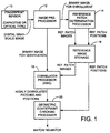
- FIG. 1 The principal components of the fingerprint feature correlator are shown in FIG. 1. These include a fingerprint sensor, indicated by reference numeral 10, which may be of the capacitive or the optical type, an image pre-processor 12, a reference patch determination processor 14, reference image storage 16, a correlator processor 18, and a geometric constraint checking processor 20.
- a fingerprint sensor indicated by reference numeral 10
- an image pre-processor 12 which may be of the capacitive or the optical type
- reference patch determination processor 14 reference image storage 16
- correlator processor 18 the principal components of the fingerprint feature correlator are shown in FIG. 1.
- the fingerprint image which is initially a gray-scale image, is converted to a binary valued image in the image preprocessor 12, which also performs other pre-processing functions, to be described with reference to FIG. 7.
- the reference patch determination processor 14 analyzes the binary fingerprint image to identify the positions of characteristic features.
- the binary image from the image preprocessor 12 is transmitted to the correlator processor 18, which also retrieves the reference patch images from the reference image storage 16. Details of operation of the correlator processor 18 will be discussed below, but briefly the processor compares each reference patch to a binarized subject fingerprint image over a full range of positions and orientations, and attempts to find a set of one or more candidate match positions for each reference patch. The correlator processor 18, therefore, identifies for each reference patch those positions and orientations (if any) at which the reference patch is highly correlated with the subject image. These data are forwarded to the geometric constraint checking processor 20, which also retrieves reference patch positions from the reference image storage 16. The geometric constraint checking processor 20 analyzes these positions to find the maximum number of candidate match positions having relative positions that are similar to the relative positions of the reference patches. The decision to accept the verification print as a match to the reference data is based on this number.
- the correlator processor 18 in the preferred embodiment of the invention is implemented as an application specific integrated circuit chip, known simply as an ASIC chip.
- the ASIC implementation allows the correlation process to be performed extremely rapidly, by means of high-speed hardware that makes good use of parallel processing in the correlation.
- the functions of the image preprocessor 12, the reference patch determination processor 14 and the geometric constraint checking processor 20 are, in the presently preferred embodiment of the invention, performed in a conventional programmable microprocessor, such as a reduced instruction set computer (RISC) processor.
- RISC reduced instruction set computer
- FIG. 3 is a sample fingerprint image reduced to binary form by the image preprocessor 12, and shows the positions of multiple reference patches, in square outlines, selected to identify the fingerprint.
- the reference patches are selected to contain combinations of bifurcations of ridges and valleys in the fingerprint image. The combination of the locations and features of the reference patches is used to identify the fingerprint uniquely without having to store an entire reference fingerprint image during enrollment and without analyzing the entire fingerprint image during verification.
- FIG. 4 shows a group of twenty-five reference patches, after conversion to a skeletonized trinary image format.
- this form only the centerlines of ridges and valleys are retained, and are stored as bits of opposite polarity. For example, ridges may be depicted as black images and stored as "1" bits , while valleys are depicted as white images and stored as "0" bits. The remaining areas of each patch are depicted as gray images.
- Each picture element, known as a pixel is stored as a two-bit data element. One bit is used to indicate whether the pixel is black or white, and the other bit is used to indicate whether the pixel has "don't care" or gray status.
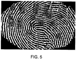
- FIG. 5 illustrates how the reference data shown in FIG. 4 are used to verify a different image of the same finger.
- This figure shows a binarized and cropped fingerprint image with reference patches from the set shown in FIG. 4 overlaid on it. The patches are shown in matching positions that satisfy the geometric constraints, as found by the verification process.
- a comparison of FIGS. 3-5 shows that, for this example, matches for many reference patches were found in the correct relative positions.
- FIG. 6 shows a similar binary image for a print that does not match the one in FIG. 3. In this case, only two of the reference patches match in the correct relative positions.
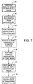
- preprocessing the fingerprint image includes image capture and quality checking, indicated in block 22, and image processing, indicated in block 24. These functions are performed in substantially the same manner in both the enrollment mode and the verification mode of operation.
- the mode is determined by a switch 26, which is typically manually operated. A practical system must include means for insuring that the enrollment mode can be activated only by authorized persons. The position of the switch 26 determines whether the binary image resulting from image processing is used in enrollment or in verification.
- the functions of image quality checking and processing are shown in more detail in FIG. 7.
- a quality check of the gray-scale image is performed, as indicated in block 28 (FIG. 7).
- the primary purpose of the quality check is to ensure that the image has not been distorted by too much or too little pressure between the finger and the fingerprint sensor. If the user applies too much pressure, the ridge images tend to merge together. Similarly, too little pressure may cause the ridges to break up.
- the quality check performs a rapid analysis of the ratio of ridge to valley area and aborts further processing if the image is not within prescribed limits.
- the next step in image processing, as indicated in block 30, is to distinguish the fingerprint area from the surrounding or background image.
- the shape of the fingerprint image is analyzed and a long axis is identified. If necessary, the image is rotated to align the long axis with a standardized direction, as indicated in block 34. All of these image processing steps reduce extraneous image content and reduce orientation uncertainty, to facilitate the later correlation of two fingerprint images taken at different times.
- each pixel of the image is converted to either black or white according to its gray-scale intensity in relation to a computed average pixel intensity of all pixels in a surrounding square region.
- the binary image may then be cropped to a standard size, as indicated in block 38, to remove empty background areas.
- a binary image of the fingerprint is ready for output to either the enrollment process or the verification process.
- the enrollment process is shown in outline in FIG. 2.
- the binary image from the image processing step 24 is first subjected to ridge and valley thinning, as indicated in block 42, to reduce every ridge and valley of the fingerprint to a single-pixel-wide line in a skeletal image. This step is performed separately for ridges and valleys.
- the two thinned images are combined, as indicated in block 44, to produce a trinary image format that will be used for reference image storage and correlation.
- ridges are shown as one color, such as black
- valleys are shown in the opposite color, such as white, and everything else is shown as gray.
- Gray pixels are treated as "don't care" pixels in the correlation process.
- the thinned images of the ridges and valleys are used in feature detection, indicated in block 46, to locate areas in which there are bifurcations of ridges or valleys.
- the identified features are analyzed in a local feature density analysis step, shown in block 48, which provides sufficient data for reference patch position selection, shown in block 50.
- the latter step selects a number of reference patch candidates that together identify the fingerprint image uniquely, for most practical purposes.
- the selected reference patches are extracted from the entire fingerprint image, as indicated in block 52, and stored for later use in the verification process, as indicated in block 54.
- the reference patch two-dimensional positions are also stored for later use in the geometric constraint checking process, indicated in block 56.
- FIG. 2 also shows a decision rule block, in which a matching patch count provided by the geometric constraint checking step 56 is compared with a threshold to determine whether there is a match or not.
- FIGS. 8 and 9 together comprise a more detailed flowchart of the functions performed in the enrollment process.
- all the blocks on the left-hand side of the figure are performed first with ridge pixels considered to be foreground pixels and valley pixels considered to be background pixels.
- the image is "cleaned up” by removing any small disconnected regions due to pores or islands in the pattern.
- the image is scanned for chains of less than, say, four foreground pixels and these are removed by changing their status to background.
- the black-white boundaries in the image are smoothed by replacing each pixel value with the majority value in a surrounding 3 ⁇ 3 neighborhood of pixels.
- the cleaned up image is thinned to a skeletal form, as indicated in block 66.
- the process for thinning is a known one in which all foreground pixels (for example all ridge pixels) that can be removed without locally disconnecting foreground regions are deleted. The process is repeatedly applied until only a thin skeletal line remains for each ridge.
- the resulting skeletal lines are further cleaned up, as indicated in block 68, by removing short segments and trimming short branches from the skeleton.
- the foregoing steps shown in blocks 62, 64, 66 and 68 are an expansion of the ridge/valley thinning block 44 in FIG. 2.
- bifurcation point map contains a "1" at the location of every acceptable bifurcation point, and a zero at every other point in the map.
- all of the foregoing steps 62, 64, 66, 68 and 70 are repeated with the foreground and background roles of the ridge and valley pixels interchanged.
- the next step, shown in block 74, is to combine the two bifurcation maps by performing a logical OR of each pair of corresponding pixels in the two maps. Then, before the combined bifurcation maps are further analyzed, the features close to the edges of the fingerprint are eliminated, as indicated in block 76. The combined maps are analyzed, as indicated in block 78 to create a local feature count image. Each pixel in the combined maps is replaced with a value that is the sum of the combined pixels within a square area surrounding the pixel being processed. This provides a count of the number of ridge and valley features within a square neighborhood around each pixel location, since each feature in the neighborhood contributes one to the local sum.
- Reference patch selection begins by finding the maximum count in the feature count image, as indicated in block 80.
- the count value is checked for a value of less than "1" in block 82. This test provides an exit from the patch selection process, to be discussed later.
- the selection process identifies all connected regions in the local feature count image that have pixels with a value equal to the maximum count value, as indicated in block 84. Each such region is treated as being indicative of a reference patch candidate.
- the location of each candidate is selected to be the centroid of the connected region, as indicated in block 86. If the candidate position is not within the corresponding region, the position is moved until a region is encountered, as indicated in block 88.
- All pixel values in the feature count image within a square neighborhood of the selected position are set to zero and, if the square neighborhood is within the image bounds of the fingerprint, the candidate position is retained. (This prevents selection of reference patches that overlap excessively.
- the process is repeated for all of the other connected regions having the maximum count value or greater. Then the count value is decremented, as indicated in block 90, and the entire process is repeated to locate additional reference patch candidates.
- the test in block 82 terminates the position selection process, and further processing continues as indicated by connector A in FIG. 9.
- the thinned images of the ridges and valleys of the fingerprint are merged to form a trinary image.
- the candidate reference patches are then extracted from this trinary image of the fingerprint, as indicated in block 94.
- Each patch position as determined by the process depicted in FIG. 8, is used as the center of a patch that is extracted or copied from the trinary image.
- the original binary image of the patch area is checked to ensure the integrity of the ridge structure in that area. If the original ridge structure is too broken, the candidate patch is rejected.
- Final smoothing is performed on the extracted patch images, as indicated in block 98, by setting each interior "white” valued pixel to "gray” if it adjoins a "black” valued pixel, and vice versa.
- the reference patches are then stored, with their positions, as indicated in block 100.
- a second image of the same fingerprint is captured, as indicated in block 102, and the verification process is applied to process the second image, as indicated in block 104. If the verification process determines that the print images match, as indicated in decision block 106, enrollment is complete. Otherwise, the entire enrollment process is repeated, as indicated in block 108, and candidate reference patches are reselected.
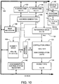
- the principal components of the correlator processor 18 are shown in FIG. 10 as including a correlation array 120 of 2,048 correlator units, associated assembly registers 122, a result first-in-first-out (FIFO) memory 124, a reference image memory 126, a subject image memory 128, and address generation logic 130 for generating addresses for the reference image memory and subject image memory.
- the address generation logic 130 has an associated X offset RAM (random access memory) 132 and a Y offset RAM 134, which are used to generate addresses to effect rotation of reference patch images with respect to the subject image.
- System clock signals to the various components are generated by a phase lock loop (PLL) clock generator 136, operating in conjunction with PLL program registers 138 and a crystal clock 140.
- PLL phase lock loop
- Test registers 144 can be used to monitor operation of the components. Communication among the components of the chip, and input and output of data are effected through a common input/output (I/O) bus 146.
- I/O input/output
- FIG. 12 is a diagram of a reference patch 150.
- each reference patch 150 is a square array of 31 ⁇ 31 pixels.
- FIG. 13 shows by way of analogy how the correlator compares a reference patch 150 (shown to smaller scale than in FIG. 12) with the entire area of a subject fingerprint image 152, which is shown as a rectangular array of pixels.
- the subject image 152 is a binary image that has been appropriately cropped and oriented in the same way as the image that was used for enrollment.
- Each reference patch is a trinary skeletal image of a selected region of the fingerprint sensed at enrollment.
- each reference patch 150 is scanned in the X-axis and Y-axis directions across the subject image 152, as indicated by the arrows in FIG. 13.
- the reference patch image 150 is compared with the underlying subject image on a pixel-by-pixel basis. A count of the non-matching pixels in the reference image is recorded for each position of the reference image with respect to the subject image, and these counts are later analyzed to select candidates for matching areas in the subject image.
- each reference patch 150 is shown in a worst-case, 45-degree orientation at 150R.
- the rotated reference patch 150R can be accommodated in a larger square reference frame 154.
- a reference frame 154 of size 45 ⁇ 45 pixels will accommodate the reference patch rotated by 45 degrees.
- the rotation is effected in the address generation logic 130, which selects reference patch addresses with appropriate X and Y offsets so that it appears that the rotated reference patch 150R is being scanned across the subject image 152.
- the X offset RAM 132 and the Y offset RAM 134 have separate tables of offset values for each angular position of the reference patch 150.
- a key feature of the correlator is that many of the pixel-by-pixel comparisons are performed in it simultaneously and in parallel.
- One aspect of this parallelism stems from the manner in which the multiple reference patches are stored as a reference image.
- sixteen reference patches are selected to represent the fingerprint image and each is 31 ⁇ 31 pixels. It will be recalled that each pixel is either a "ridge” pixel, a “valley” pixel or a "gray” pixel.
- each pixel uses two bits of data, wherein "00" represents a “valley” pixel, "01” represents a “ridge” pixel and "10" is “gray” or “don't care.”
- the sixteen patches are overlaid as two-bit bitplanes in the reference image 126.
- One pixel representing the same location in each of the sixteen patches is stored as a 32-bit word.
- the entire reference frame 154 (FIG. 12) can be stored in 45 ⁇ 45 or 2,025 words, which is why the reference image 126 is shown as having 2k (2,048) bits.
- This storage arrangement allows all 16 patches to be manipulated together as if they were a single image, as will shortly be explained with specific reference to FIG. 14, which shows relevant portions of the correlator in more detail.
- the correlation array 120 is shown as including 128 rows of sixteen correlation units 120u, and the assembly registers 122 are shown as including assembly staging registers 122a and an assembly shift register 122b.
- sixteen pairs of bits are input from the reference image to the sixteen columns of correlation units 120u.
- the vertical lines connecting the respective columns of correlation units are not intended imply that the columns operate like shift registers. Rather, each input line from the reference image 126 is applied to all the correlation units 120u in a column simultaneously, in parallel.
- the pixel data from the subject image 128 are input to the correlator array 120 in a row-wise fashion. Again, the horizontal lines connecting the correlation units 120u are not intended to imply shift registers, but the application of each bit of input to all the units in a row in parallel. Pixel data are input from the subject image 128 in thirty-two-bit segments corresponding to thirty-two adjacent pixels in a horizontal row of the subject image.
- each of the pixels in a segment of 128 pixels of the subject image is compared with one pixel from each of the sixteen reference image patches.
- the correlator units 120u will generate match or no-match conditions that will be further processed at the conclusion of the correlation.
- the assembly shift register 122b shifts the stored pixels by one bit or pixel, in an upward direction as represented in the figure.
- the second pixel from all of the reference patches is compared with a second set of 128 pixels from the subject image, offset by one pixel with respect to the first set. For example, if the first set of pixels is represented as including pixel #0 through pixel #127, the second set, after shifting, will include pixel #1 through pixel #128.
- the assembly shift register has 128 output bits or pixels, it has 160 shift register positions internally, to provide enough bit positions for shifting a full reference patch width.
- This process of comparing and shifting continues until every pixel in a full row of the reference patches has been compared with a correspondingly positioned pixel in part of a row of the subject image. Then the second row or pixels in the reference patches is similarly processed. This requires the input of pixels from a second row of the subject image. This process continues until all the pixels in the reference patches have been compared with correspondingly positioned pixels in the subject image. At this point, all the reference patches have been compared with subject image patches at 128 different patch positions along the horizontal axis of the subject image. The entire matching process is started over again using subject image pixels taken from a new position in the subject image first row, that is, beginning with pixel #128 in the first row. In effect, the reference patches are translated 128 pixels to the right. This transition to a second block of pixels in the subject image is represented by the first of four vertical dotted lines in FIG. 13. In the embodiment illustrated, the subject image 152 has five such blocks of pixels and is 640 pixels wide.
- the correlation process is continued for different Y-axis positions on the subject image, until the reference patches have been, in effect, translated across the entire subject image in a raster scan. Finally, the correlation process is repeated using different selected rotational orientations of the reference patches.
- Block 162 shows a parallel compare operation in which one selected pixel of all of the reference patches is compared with 128 adjacent pixels in a row of the subject image.
- the X position is advanced both for the reference patches and for the subject image row being processed, as indicated in block 164.
- the steps indicated in blocks 162 and 164 are repeated until the end of the reference patch row is reached, as determined in decision block, 166.
- the Y position is advanced both for the reference patches and for the subject image, as indicated in block 168, so that the next row of the reference patches can be compared with the next row of the subject image.
- this is equivalent to a translation of the reference patches across the top of the subject image in an X direction, by a total displacement of 128 pixels.
- the end of a correlation processing sequence in which all the pixels in the multiple patches have been compared with multiple pixels in the subject image is determined as indicated in decision block 170.
- the correlation results, which are being accumulated in the correlator units 120u, are saved for future processing, and the X axis position in the subject image is advanced to the next block of 128 pixels in the subject image row, as indicated in block 172.
- Correlation processing continues in that block in the same way as in the previous block. This results in the saving of another set of results from the correlator units 120u.
- each correlator unit 120u includes a six-bit down-counter 190, an AND gate 192, an exclusive OR gate 194 and a result register 196.
- the exclusive OR gate 194 has one input line from a reference pixel and one input line from a subject pixel with which a comparison is being made.
- This output signal on line 198 is one of four inputs to the AND gate 192.
- the other three inputs are: a compare-enable signal, which initiates the comparison process, an inverted "don't use” signal from the second bit of the two-bit reference pixel, and an inverted zero-count signal from the six-bit down-counter 190.
- the AND gate 192 produces a logical "1" output on line 200, which is connected to the count-enable input to the down-counter 190.
- the counter 190 also has an input for a "patch threshold” count and a load enable input that stores the patch threshold in the counter. Initially, and whenever the count results are saved, as indicated in block 174 (FIG. 11), the counter 190 is reset to a selected number, the patch threshold count. Whenever there is a non-matching compare operation, the counter 190 is decremented by one.
- the contents of the counter 190 are output on lines 204 and saved in the result register 196, along with identifying data defining the position of the patch that has been compared in the subject image. If the counter 190 is counted down to zero, indicating a very low degree of matching, a zero output on line 206 is fed back to the AND gate 192 to disable further counting.
- each data record written to the result register 196 includes the counter value, the patch number and the location in the subject image.
- the location in the subject image includes X,Y coordinates and a rotation angle, if any.
- FIG. 16 depicts how the match count results are processed to select likely candidates for matching areas of the subject image.
- the results for each reference patch are sorted into a list by increasing mismatch count, as indicated in block 212. It will be recalled that higher counts indicate a higher degree of match because mismatching pixels cause counting downward. Then the best match is selected, for the patch being processed, as indicated in block 214.
- decision block 216 a question is posed to determine whether there is another match to consider. This decision block terminates processing of matches for a particular patch.
- the next best match is selected, as shown in block 218, and the distance between this match position and the position of the best match is computed, as indicated in block 220.
- Good matching positions will be located in clusters in the subject image. Movement of the reference patch by just one or two pixels out of registration with the best match position will, in general, still result in a high degree of match between the two images.
- the principle of the process steps shown in FIG. 16 is to eliminate match candidates that are so close to the best match position as to be considered part of the same matching cluster of candidates. If the distance between the current match candidate and the best match candidate is below a selected threshold, as determined in decision block 222, the current match selection is discarded as a candidate, as indicated in block 224. Otherwise, the current match selection is retained as a candidate, as indicated in block 226.
- Processing then continues in block 216, to determine if there is another match to analyze. Once all the matches for a selected reference patch have been examined in this way, as determined in block 216, another reference patch is selected and processing continues in block 214, in which the best match for the new reference patch is selected. Once all the reference patches have been processed, as determined in decision block 228, this phase of match result processing is complete.
- match candidates for each of the reference patches.
- the number of match candidates will depend in part on the patch threshold count with which the counters 190 are initialized before comparing each patch with an area of the subject image.
- the final phase in processing is to determine whether there is a set of match candidates that has a desired degree of geometrical congruity with the set of reference patches.
- congruity between the constellation of reference patches and a corresponding constellation of candidate patches in the subject image is determined by comparing the distances between all possible pairs of the reference patches with the distances between corresponding pairs of candidate patches in the subject image. What renders this process difficult is that there may be, and usually are, more than one match candidate for each reference patch.
- FIG. 17 depicts the broad steps performed in determining whether these geometric constraints have been satisfied. First, as indicated in block 240, the distances between all possible pairs of reference patches are determined.
- Distinct match candidates are those pertaining to distinct reference patches. Excluded from this step is the determination of distances between any pair of match candidates pertaining to the same reference patch. As indicated in block 244, the next step is to choose a maximal feasible subset of the distinct match candidates. A subset of the distinct match candidates is said to be "feasible” if every possible pair of distinct match candidates in that subset satisfies a geometric constraint when compared with the corresponding pair of reference patches.
- the geometric constraint used in the presently preferred embodiment of the invention is that the distance between the pair of match candidates under consideration is approximately equal to the distance between the corresponding pair of reference patches, within some selected tolerance.
- the selection process in block 244 searches for a feasible subset whose size (i.e., number of elements) exceeds a preset threshold. If such a feasible subset is found, the result of the selection process is the size of this set. Otherwise, the result is the size of the largest feasible subset. If this number is large enough, as determined in decision block 246, a match condition is declared, as indicated at 248. Otherwise, a non-match condition is declared, as indicated at 250.
- the critical step of selecting a maximal feasible subset of distinct match candidates is shown in more detail in FIG. 18.
- this step may be implemented.
- One way is to simply search the entire subset of distinct match candidates for a first pair that matches the geometric constraint, and then to search again for a third candidate that meets the geometric constraint with respect to the first selected pair. The search can then be repeated in the same way for a additional candidates that satisfy the geometric constraints with respect to candidates already selected.
- This technique is time consuming and computationally intensive, so the presently preferred approach makes use of some intelligent shortcuts, based largely on the concept of a match candidate matrix. This is an N ⁇ N matrix of binary terms (1 or 0), where N is the total number of match candidates.
- Distinctness means that the two candidates corresponding to the row and column numbers of the matrix term must be candidates for matching different reference patches, not the same reference patch. Satisfying the geometric constraint requirement means that the distance between the two match candidates corresponding to the row and column number of the matrix term must be approximately equal to the distance between the corresponding pair of reference patches. If a pair of match candidates does not satisfy either the distinctness requirement or the geometric constraint requirement, then the matrix term corresponding to that pair of match candidates will be zero.
- the matrix, computed as indicated in block 252 will be symmetrical about its diagonal of all zeros, so that fewer that half of its terms have to be computed to generate the complete matrix.
- the matrix provides a simple way to eliminate weak match candidates without performing a search.
- a weak match candidate is one whose row (or column, because the matrix is symmetrical) has too few "ones," indicating that the candidate does not meet the geometric constraint requirement with respect to very many corresponding reference patches. For example, in a system using sixteen reference patches, as described above, one may choose as a match criterion that there must be at least four match candidates that satisfy the geometric constraints. If any row or column of the matrix has fewer than four "ones,” the match candidate corresponding to this row or column may be eliminated. By the same logic, after elimination of such rows and columns, if there remain other rows and columns with fewer than four "ones,” then these rows and columns should also be eliminated.
- a no-match condition (250) is immediately declared. Otherwise, a search is initiated for a sufficiently large feasible subset, as indicated in block 258. The details of this search process are shown in FIG. 19, which is described in detail below. The results of this search are the size of the feasible subset, and an average pixel mismatch score for the patches in the feasible subset. The size is compared to an "accept" threshold, and a match is declared if the size exceeds the threshold, as indicated in decision block 260. Otherwise, if the feasible subset size is less than a "reject" threshold (which is lower than the accept threshold), then a non-match is declared, as indicated in decision block 262. If the feasible set size is between the accept and reject thresholds, the match decision is made by comparing the pixel mismatch score to a third threshold, as indicated in decision block 264.
- the match candidate matrix is central to efficiently organizing the search for a sufficiently large feasible subset.
- Another useful concept is the notion of a canonical representation of a feasible subset.
- the canonical representation of any set of match candidates is defined as an increasing sequence of distinct match candidate matrix column (or row) numbers corresponding to elements of the set. (Requiring an increasing order eliminates redundant enumerations of the same set).
- the canonical representation will be abbreviated as FCR, for feasible canonical representation.
- Yet another useful concept is that of the successor set S(n) (or simply the successors).
- the successor set S(n) for a match candidate of index n is the set of all match candidate indices greater than n for which the corresponding match candidates satisfy the geometric constraint. Equivalently, as viewed in the match candidate matrix, S(n) is a list of all column indices in row n of the matrix for which the corresponding matrix element value is one.
- FIGS. 20A through 20F are a collection of tree diagrams that enumerate all the possible feasible subsets for the matrix of FIG. 19.
- Each tree corresponds to the collection of feasible subsets with canonical representations whose first element equals the root value.
- These trees have the property that if one starts at the root node (at the left of each tree) and traverses any branch, then the sequence of numbers in successive descendent nodes is a canonical representation of a feasible set.
- the canonical representations ⁇ 1, 2, 5 ⁇ and ⁇ 1, 5 ⁇ are contained in the first tree.
- trees exemplify the following general rule: the descendants of any non-root node are the cumulative intersection of the successor sets of its ancestors with the successors of that node. (A root node's descendants are simply its successors.) For any given root node, the corresponding tree is thus generated by recursively applying this rule. The size of the maximal feasible subset is found by generating a tree for each possible root node, and determining the maximum depth of these trees.
- FIG. 21 depicts a procedure for finding the size of a maximal feasible subset. (This figure implements the process referred to in block 244 of FIG. 17.)
- the current maximum feasible set size is first set to zero, as indicated in block 270.
- One of the remaining match candidates is selected as the root node, as indicated in block 272.
- a search set is then defined, as indicated in block 274, to obtain the successors to the current root candidate.
- a recursive subroutine is then called, as indicated in block 276, to find the depth of each sub-tree rooted in the search set. This subroutine also updates the current maximum feasible set size whenever it finds a feasible set larger than the current size.
- the current maximum feasible set size exceeds a high threshold, as determined in decision block 246, a match is declared. Otherwise, if there are no untried candidates, as determined in decision block 280, this process repeats (starting from block 272) until all candidates have been examined. If all root candidates are examined without a match being declared, the current maximum feasible subset size is compared to a low threshold, as determined in decision block 262. If it is below this threshold, a non-match is immediately declared. Otherwise, the average number of mismatched pixels for the reference patches in the maximum feasible subset is computed, as indicated in block 282. If this value is above a threshold, as determined in decision block 264, a non-match is declared; otherwise a match.
- FIG. 22 shows in more detail the recursive subroutine called in block 276 of FIG. 21.
- the current search set, the parent node and the size of the current feasible set are passed as parameters to this subroutine and are accepted as indicated in block 290.
- Each invocation of this subroutine maintains independent copies of these parameters.
- An angle test which will be described below, is applied to each element in the search set. Elements that fail the test are removed from the search set, as indicated in block 292. If the search set is then empty, as determined in decision block 294, the subroutine immediately returns. If the current feasible set size exceeds the maximum size seen so far, as determined in decision block 296, then the maximum depth is updated, as depicted in block 298.
- this size also exceeds a high threshold, as determined in decision block 300, a match is immediately declared. Otherwise, as indicated in block 302, a new parent node element is selected from the search set, and the successor set for this element is found. A new search set, consisting of the intersection of the current search set and the new parent node's successor set, is created, as indicated in block 304. The procedure then calls itself, as indicated in block 306, passing the current feasible set plus one, the new parent node, and the new search set as parameters. After returning from this call, the process repeats itself from block 302 until all elements have been examined, as determined in decision block 308, whereupon the procedure returns.
- the angle test referred to previously in block 292 makes the test of geometrical congruence more stringent. Because the geometric constraints only consider distance, they allow a constellation of positions to be matched with mirror images, as well as with legitimately congruent constellations. A test to eliminate this possibility can be incorporated into the search procedure. Consider three successive match candidates in an FCR. Label the points in the X-Y coordinate planes corresponding to the positions of the match candidates as S1, S2 and S3, respectively. Call the positions of the corresponding reference patches R1, R2, R3. Now compare the angle between the ray S1-S2 and the ray S2-S3 to the angle between the corresponding reference rays R1-R2 and R2-R3.
- the present invention represents a significant advance in the field of fingerprint feature correlation.
- the invention provides for the verification of a subject fingerprint image by comparing it with multiple reference image patches in parallel.
- the reference image patches are scanned, in various angular orientations, across the entire subject image, to locate the positions of match candidate patches corresponding to the reference patches.
- the match candidates are further processed to identify a subset of them that satisfies geometric congruency requirements with respect to the reference patches.
- the number of match candidates in this subset determines whether or not the subject fingerprint image matches another fingerprint image generated during enrollment and used to derive the reference patches.
Landscapes
- Engineering & Computer Science (AREA)
- Theoretical Computer Science (AREA)
- Computer Vision & Pattern Recognition (AREA)
- Multimedia (AREA)
- General Physics & Mathematics (AREA)
- Physics & Mathematics (AREA)
- Computing Systems (AREA)
- General Health & Medical Sciences (AREA)
- Medical Informatics (AREA)
- Software Systems (AREA)
- Evolutionary Computation (AREA)
- Databases & Information Systems (AREA)
- Artificial Intelligence (AREA)
- Health & Medical Sciences (AREA)
- Human Computer Interaction (AREA)
- Collating Specific Patterns (AREA)
- Measurement Of The Respiration, Hearing Ability, Form, And Blood Characteristics Of Living Organisms (AREA)
Applications Claiming Priority (2)
| Application Number | Priority Date | Filing Date | Title |
|---|---|---|---|
| US995330 | 1997-11-22 | ||
| US08/995,330 US6134340A (en) | 1997-12-22 | 1997-12-22 | Fingerprint feature correlator |
Publications (3)
| Publication Number | Publication Date |
|---|---|
| EP0918300A2 true EP0918300A2 (de) | 1999-05-26 |
| EP0918300A3 EP0918300A3 (de) | 1999-11-24 |
| EP0918300B1 EP0918300B1 (de) | 2003-01-08 |
Family
ID=25541667
Family Applications (1)
| Application Number | Title | Priority Date | Filing Date |
|---|---|---|---|
| EP98120186A Expired - Lifetime EP0918300B1 (de) | 1997-11-22 | 1998-10-29 | Merkmalkorrelator für Fingerabdrücke |
Country Status (4)
| Country | Link |
|---|---|
| US (1) | US6134340A (de) |
| EP (1) | EP0918300B1 (de) |
| JP (1) | JP3053388B2 (de) |
| DE (1) | DE69810581T2 (de) |
Cited By (14)
| Publication number | Priority date | Publication date | Assignee | Title |
|---|---|---|---|---|
| WO2001038506A1 (de) * | 1999-11-22 | 2001-05-31 | Siemens Aktiengesellschaft | Initialisierung eines zugangskontrollsystems |
| WO2001084478A1 (en) * | 2000-04-28 | 2001-11-08 | Precise Biometrics Ab | Check of fingerprints |
| WO2002007070A1 (en) * | 2000-07-17 | 2002-01-24 | Precise Biometrics Ab | Device and method for fingerprints supervision |
| WO2003025836A1 (en) * | 2001-09-04 | 2003-03-27 | Hewlet-Packard Company | Biometric sensor |
| EP1313026A1 (de) | 2000-05-31 | 2003-05-21 | Hitachi, Ltd. | Authentifizierungssystem für lebende körper |
| WO2003069542A1 (en) * | 2002-02-18 | 2003-08-21 | Precise Biometrics Ab | Method and device for recording fingerprint data |
| WO2003085589A1 (en) * | 2002-04-05 | 2003-10-16 | Identix Incorporated | Vision-based operating method and system |
| WO2004006495A1 (en) * | 2002-07-09 | 2004-01-15 | Prosection Ab | A method and a system for biometric identification or verification |
| EP1492058A2 (de) * | 2003-06-23 | 2004-12-29 | Canadian Bank Note Company, Ltd. | Optisches Echtheitsüberprüfungssystem für Dokumente |
| WO2005034021A1 (en) | 2003-10-01 | 2005-04-14 | Authentec, Inc. | Methods for finger biometric processing and associated finger biometric sensors |
| US7035441B2 (en) | 2000-04-28 | 2006-04-25 | Precise Biometrics Ab | Check for fingerprints |
| EP1650694A1 (de) * | 2000-09-06 | 2006-04-26 | Hitachi, Ltd. | Vorrichtung und Verfahren zur Personenidentifizierung |
| US7627145B2 (en) | 2000-09-06 | 2009-12-01 | Hitachi, Ltd. | Personal identification device and method |
| CN105160315A (zh) * | 2015-08-31 | 2015-12-16 | 宇龙计算机通信科技(深圳)有限公司 | 一种指纹验证方法、装置及终端 |
Families Citing this family (116)
| Publication number | Priority date | Publication date | Assignee | Title |
|---|---|---|---|---|
| US6504957B2 (en) | 1997-07-07 | 2003-01-07 | General Electric Company | Method and apparatus for image registration |
| US6496594B1 (en) * | 1998-10-22 | 2002-12-17 | Francine J. Prokoski | Method and apparatus for aligning and comparing images of the face and body from different imagers |
| ATE358854T1 (de) | 1998-12-28 | 2007-04-15 | Casio Computer Co Ltd | Gerät und verfahren zum bildvergleich |
| US6826294B1 (en) * | 1999-03-05 | 2004-11-30 | Koninklijke Philips Electronics N.V. | Block matching motion estimation using reduced precision clustered predictions |
| JP3415492B2 (ja) * | 1999-06-24 | 2003-06-09 | Necエレクトロニクス株式会社 | 指紋照合システムとその指紋照合方法 |
| SG67584A1 (en) * | 1999-07-08 | 2001-02-20 | Ct For Signal Proc Of The Nany | Two-stage local and global fingerprint matching technique for automated fingerprint verification/indentification |
| JP3679953B2 (ja) * | 1999-09-14 | 2005-08-03 | 富士通株式会社 | 生体情報を用いた個人認証システム |
| US8479012B1 (en) * | 1999-10-19 | 2013-07-02 | Harris Technology, Llc | Using biometrics as an encryption key |
| JP2001117579A (ja) | 1999-10-21 | 2001-04-27 | Casio Comput Co Ltd | 音声照合装置、音声照合方法、及び音声照合処理プログラムを記憶した記憶媒体 |
| US8036431B1 (en) * | 1999-10-29 | 2011-10-11 | Identix Incorporated | Portable apparatus for identification verification |
| US6418436B1 (en) * | 1999-12-20 | 2002-07-09 | First Data Corporation | Scoring methodology for purchasing card fraud detection |
| US6836554B1 (en) * | 2000-06-16 | 2004-12-28 | International Business Machines Corporation | System and method for distorting a biometric for transactions with enhanced security and privacy |
| US6898301B2 (en) * | 2000-07-10 | 2005-05-24 | Casio Computer Co., Ltd. | Authentication system based on fingerprint and electronic device employed for the system |
| EP1312040B1 (de) | 2000-08-18 | 2006-04-05 | Cross Match Technologies, Inc. | System und verfahren zum automatischen steuern eines fingerabdruckabtasters |
| US6766040B1 (en) | 2000-10-02 | 2004-07-20 | Biometric Solutions, Llc | System and method for capturing, enrolling and verifying a fingerprint |
| US6990219B2 (en) * | 2000-12-15 | 2006-01-24 | Nippon Telegraph And Telephone Corporation | Image capturing method and apparatus and fingerprint collation method and apparatus |
| US6895104B2 (en) * | 2001-02-16 | 2005-05-17 | Sac Technologies, Inc. | Image identification system |
| US7184026B2 (en) * | 2001-03-19 | 2007-02-27 | Avago Technologies Ecbu Ip (Singapore) Pte. Ltd. | Impedance sensing screen pointing device |
| JP2002358524A (ja) * | 2001-05-31 | 2002-12-13 | Sony Corp | 指紋照合装置及び指紋照合方法 |
| US6944321B2 (en) | 2001-07-20 | 2005-09-13 | Activcard Ireland Limited | Image distortion compensation technique and apparatus |
| FR2829264A1 (fr) * | 2001-09-04 | 2003-03-07 | St Microelectronics Sa | Procede de comparaison d'empreintes digitales |
| US20030229811A1 (en) * | 2001-10-31 | 2003-12-11 | Cross Match Technologies, Inc. | Method that provides multi-tiered authorization and identification |
| KR100453220B1 (ko) * | 2001-12-05 | 2004-10-15 | 한국전자통신연구원 | 지문 특징점을 이용한 사용자 인증 장치 및 방법 |
| JP4262471B2 (ja) * | 2002-11-12 | 2009-05-13 | 富士通株式会社 | 生体特徴データ取得装置 |
| US20040123113A1 (en) * | 2002-12-18 | 2004-06-24 | Svein Mathiassen | Portable or embedded access and input devices and methods for giving access to access limited devices, apparatuses, appliances, systems or networks |
| US7085433B2 (en) * | 2003-01-06 | 2006-08-01 | Banner Engineering Corp. | System and method for performing rotational and translational testing for a reference image used in a normalized gray scale pattern find system |
| WO2004072918A2 (en) * | 2003-02-17 | 2004-08-26 | Kinderguard Limited | A tracking and monitoring apparatus and system |
| US8171304B2 (en) * | 2003-05-15 | 2012-05-01 | Activcard Ireland Limited | Method, system and computer program product for multiple biometric template screening |
| US7450741B2 (en) * | 2003-06-23 | 2008-11-11 | Motorola, Inc. | Gray scale matcher |
| US20050063562A1 (en) * | 2003-08-07 | 2005-03-24 | Brunk Hugh L. | Conveying fingerprint minutiae with digital watermarks |
| US7214953B2 (en) * | 2003-09-05 | 2007-05-08 | Authentec, Inc. | Multi-biometric finger sensor including optical dispersion sensing pixels and associated methods |
| US7351974B2 (en) * | 2003-09-05 | 2008-04-01 | Authentec, Inc. | Integrated circuit infrared sensor and associated methods |
| WO2005031636A1 (en) * | 2003-09-24 | 2005-04-07 | Authentec, Inc. | Finger biometric sensor with sensor electronics distributed over thin film and monocrystalline substrates and related methods |
| US7599530B2 (en) * | 2003-10-01 | 2009-10-06 | Authentec, Inc. | Methods for matching ridge orientation characteristic maps and associated finger biometric sensor |
| US7787667B2 (en) * | 2003-10-01 | 2010-08-31 | Authentec, Inc. | Spot-based finger biometric processing method and associated sensor |
| JP4340553B2 (ja) * | 2004-02-06 | 2009-10-07 | 富士通株式会社 | 生体情報照合装置 |
| JP3996133B2 (ja) * | 2004-02-16 | 2007-10-24 | シャープ株式会社 | 画像照合装置、画像照合方法、画像照合プログラム、および画像照合プログラムを記録したコンピュータ読取可能な記録媒体 |
| US8175345B2 (en) | 2004-04-16 | 2012-05-08 | Validity Sensors, Inc. | Unitized ergonomic two-dimensional fingerprint motion tracking device and method |
| US8131026B2 (en) | 2004-04-16 | 2012-03-06 | Validity Sensors, Inc. | Method and apparatus for fingerprint image reconstruction |
| US8165355B2 (en) | 2006-09-11 | 2012-04-24 | Validity Sensors, Inc. | Method and apparatus for fingerprint motion tracking using an in-line array for use in navigation applications |
| US8229184B2 (en) | 2004-04-16 | 2012-07-24 | Validity Sensors, Inc. | Method and algorithm for accurate finger motion tracking |
| US8447077B2 (en) | 2006-09-11 | 2013-05-21 | Validity Sensors, Inc. | Method and apparatus for fingerprint motion tracking using an in-line array |
| US8358815B2 (en) | 2004-04-16 | 2013-01-22 | Validity Sensors, Inc. | Method and apparatus for two-dimensional finger motion tracking and control |
| EP1747525A2 (de) * | 2004-04-23 | 2007-01-31 | Validity Sensors Inc. | Verfahren und vorrichtungen zum beschaffen eines durchgezogenen figerabdruckbildes |
| US8055027B2 (en) * | 2004-06-30 | 2011-11-08 | Bio-Key International, Inc. | Generation of directional field information in the context of image processing |
| US20060034497A1 (en) * | 2004-08-15 | 2006-02-16 | Michael Manansala | Protometric authentication system |
| EP1800243B1 (de) | 2004-10-04 | 2010-08-11 | Validity Sensors, Inc. | Fingerabdruckerfassende konstruktionen mit einem substrat |
| WO2006044815A1 (en) * | 2004-10-13 | 2006-04-27 | Authentec, Inc. | Finger sensing device for navigation and related methods |
| JP4501627B2 (ja) * | 2004-10-19 | 2010-07-14 | カシオ計算機株式会社 | 画像照合装置、画像照合方法、画像照合プログラム |
| US20070097755A1 (en) * | 2005-10-27 | 2007-05-03 | Marndi Raj N | Method for comparing a first data set with a second data set |
| US7844774B2 (en) * | 2005-11-16 | 2010-11-30 | Sun Microsystems, Inc. | Extensible fingerprinting functions and content addressed storage system using the same |
| JP4961214B2 (ja) * | 2006-03-29 | 2012-06-27 | 株式会社日立情報制御ソリューションズ | 生体認証方法およびシステム |
| US20070263913A1 (en) * | 2006-05-15 | 2007-11-15 | Daniel Sam M | Matching methods and apparatus using landmark points in a print |
| US8081805B2 (en) * | 2006-06-19 | 2011-12-20 | Authentec, Inc. | Finger sensing device with multiple correlators and associated methods |
| US20080101663A1 (en) * | 2006-10-31 | 2008-05-01 | Motorola, Inc. | Methods for gray-level ridge feature extraction and associated print matching |
| EP2137599A1 (de) * | 2007-03-14 | 2009-12-30 | AXSionics AG | Druckmessvorrichtung und entsprechendes verfahren |
| US8107212B2 (en) | 2007-04-30 | 2012-01-31 | Validity Sensors, Inc. | Apparatus and method for protecting fingerprint sensing circuitry from electrostatic discharge |
| US8290150B2 (en) | 2007-05-11 | 2012-10-16 | Validity Sensors, Inc. | Method and system for electronically securing an electronic device using physically unclonable functions |
| US8204281B2 (en) | 2007-12-14 | 2012-06-19 | Validity Sensors, Inc. | System and method to remove artifacts from fingerprint sensor scans |
| US8276816B2 (en) | 2007-12-14 | 2012-10-02 | Validity Sensors, Inc. | Smart card system with ergonomic fingerprint sensor and method of using |
| US8116540B2 (en) | 2008-04-04 | 2012-02-14 | Validity Sensors, Inc. | Apparatus and method for reducing noise in fingerprint sensing circuits |
| US8005276B2 (en) | 2008-04-04 | 2011-08-23 | Validity Sensors, Inc. | Apparatus and method for reducing parasitic capacitive coupling and noise in fingerprint sensing circuits |
| US8682056B2 (en) * | 2008-06-30 | 2014-03-25 | Ncr Corporation | Media identification |
| WO2010036445A1 (en) | 2008-07-22 | 2010-04-01 | Validity Sensors, Inc. | System, device and method for securing a device component |
| US8391568B2 (en) | 2008-11-10 | 2013-03-05 | Validity Sensors, Inc. | System and method for improved scanning of fingerprint edges |
| CN101770299B (zh) * | 2008-12-26 | 2013-11-06 | 深圳富泰宏精密工业有限公司 | 导航键功能实现系统及方法 |
| KR101581197B1 (ko) * | 2009-01-06 | 2015-12-30 | 삼성전자주식회사 | 로봇 및 그 제어방법 |
| US8600122B2 (en) | 2009-01-15 | 2013-12-03 | Validity Sensors, Inc. | Apparatus and method for culling substantially redundant data in fingerprint sensing circuits |
| US8278946B2 (en) | 2009-01-15 | 2012-10-02 | Validity Sensors, Inc. | Apparatus and method for detecting finger activity on a fingerprint sensor |
| US8374407B2 (en) | 2009-01-28 | 2013-02-12 | Validity Sensors, Inc. | Live finger detection |
| US8799666B2 (en) | 2009-10-06 | 2014-08-05 | Synaptics Incorporated | Secure user authentication using biometric information |
| US9336428B2 (en) | 2009-10-30 | 2016-05-10 | Synaptics Incorporated | Integrated fingerprint sensor and display |
| US9274553B2 (en) | 2009-10-30 | 2016-03-01 | Synaptics Incorporated | Fingerprint sensor and integratable electronic display |
| US9400911B2 (en) | 2009-10-30 | 2016-07-26 | Synaptics Incorporated | Fingerprint sensor and integratable electronic display |
| US8421890B2 (en) | 2010-01-15 | 2013-04-16 | Picofield Technologies, Inc. | Electronic imager using an impedance sensor grid array and method of making |
| US8791792B2 (en) | 2010-01-15 | 2014-07-29 | Idex Asa | Electronic imager using an impedance sensor grid array mounted on or about a switch and method of making |
| US8866347B2 (en) | 2010-01-15 | 2014-10-21 | Idex Asa | Biometric image sensing |
| US8041956B1 (en) | 2010-08-16 | 2011-10-18 | Daon Holdings Limited | Method and system for biometric authentication |
| US8520903B2 (en) * | 2010-02-01 | 2013-08-27 | Daon Holdings Limited | Method and system of accounting for positional variability of biometric features |
| US9666635B2 (en) | 2010-02-19 | 2017-05-30 | Synaptics Incorporated | Fingerprint sensing circuit |
| US8716613B2 (en) | 2010-03-02 | 2014-05-06 | Synaptics Incoporated | Apparatus and method for electrostatic discharge protection |
| US9001040B2 (en) | 2010-06-02 | 2015-04-07 | Synaptics Incorporated | Integrated fingerprint sensor and navigation device |
| US8331096B2 (en) | 2010-08-20 | 2012-12-11 | Validity Sensors, Inc. | Fingerprint acquisition expansion card apparatus |
| US8538097B2 (en) | 2011-01-26 | 2013-09-17 | Validity Sensors, Inc. | User input utilizing dual line scanner apparatus and method |
| US8594393B2 (en) | 2011-01-26 | 2013-11-26 | Validity Sensors | System for and method of image reconstruction with dual line scanner using line counts |
| GB2489100A (en) | 2011-03-16 | 2012-09-19 | Validity Sensors Inc | Wafer-level packaging for a fingerprint sensor |
| US10043052B2 (en) | 2011-10-27 | 2018-08-07 | Synaptics Incorporated | Electronic device packages and methods |
| US9195877B2 (en) | 2011-12-23 | 2015-11-24 | Synaptics Incorporated | Methods and devices for capacitive image sensing |
| US9785299B2 (en) | 2012-01-03 | 2017-10-10 | Synaptics Incorporated | Structures and manufacturing methods for glass covered electronic devices |
| US9330294B2 (en) | 2012-01-26 | 2016-05-03 | Aware, Inc. | System and method of capturing and producing biometric-matching quality fingerprints and other types of dactylographic images with a mobile device |
| US9251329B2 (en) | 2012-03-27 | 2016-02-02 | Synaptics Incorporated | Button depress wakeup and wakeup strategy |
| US9268991B2 (en) | 2012-03-27 | 2016-02-23 | Synaptics Incorporated | Method of and system for enrolling and matching biometric data |
| US9137438B2 (en) | 2012-03-27 | 2015-09-15 | Synaptics Incorporated | Biometric object sensor and method |
| US9600709B2 (en) | 2012-03-28 | 2017-03-21 | Synaptics Incorporated | Methods and systems for enrolling biometric data |
| US9152838B2 (en) | 2012-03-29 | 2015-10-06 | Synaptics Incorporated | Fingerprint sensor packagings and methods |
| EP2958052B1 (de) | 2012-04-10 | 2020-10-07 | Idex Asa | Biometrische erfassung |
| US9436864B2 (en) * | 2012-08-23 | 2016-09-06 | Apple Inc. | Electronic device performing finger biometric pre-matching and related methods |
| US8824758B2 (en) * | 2012-11-07 | 2014-09-02 | Sony Corporation | Method and apparatus for orienting tissue samples for comparison |
| US9183365B2 (en) | 2013-01-04 | 2015-11-10 | Synaptics Incorporated | Methods and systems for fingerprint template enrollment and distribution process |
| US9665762B2 (en) | 2013-01-11 | 2017-05-30 | Synaptics Incorporated | Tiered wakeup strategy |
| JP6376873B2 (ja) * | 2014-07-16 | 2018-08-22 | キヤノン株式会社 | 画像処理装置、画像処理方法及びプログラム |
| CN105389565B (zh) * | 2015-11-13 | 2019-04-02 | Oppo广东移动通信有限公司 | 指纹注册方法、装置和终端设备 |
| CN105574161B (zh) * | 2015-12-15 | 2017-09-26 | 徐庆 | 一种商标图形要素识别方法、装置和系统 |
| WO2018074601A1 (ja) | 2016-10-21 | 2018-04-26 | 日本電気株式会社 | 合成装置、合成方法及びプログラム |
| US11036961B2 (en) * | 2016-10-26 | 2021-06-15 | Nec Corporation | Striped pattern image examination support apparatus, striped pattern image examination support method, and program |
| US10506926B2 (en) | 2017-02-18 | 2019-12-17 | Arc Devices Limited | Multi-vital sign detector in an electronic medical records system |
| US10492684B2 (en) | 2017-02-21 | 2019-12-03 | Arc Devices Limited | Multi-vital-sign smartphone system in an electronic medical records system |
| JP6790995B2 (ja) * | 2017-04-27 | 2020-11-25 | 富士通株式会社 | 照合装置、照合方法および照合プログラム |
| EP3441905A4 (de) * | 2017-06-12 | 2019-04-10 | Shenzhen Goodix Technology Co., Ltd. | Verfahren, vorrichtung und system zur messung der fingerfeuchtigkeit |
| US10602548B2 (en) | 2017-06-22 | 2020-03-24 | Infineon Technologies Ag | System and method for gesture sensing |
| US10354116B2 (en) * | 2017-07-06 | 2019-07-16 | Synaptics Incorporated | Optical fingerprint sensor with scattered light image detection |
| US10602987B2 (en) | 2017-08-10 | 2020-03-31 | Arc Devices Limited | Multi-vital-sign smartphone system in an electronic medical records system |
| US10977106B2 (en) * | 2018-02-09 | 2021-04-13 | Microsoft Technology Licensing, Llc | Tree-based anomaly detection |
| US10485431B1 (en) | 2018-05-21 | 2019-11-26 | ARC Devices Ltd. | Glucose multi-vital-sign system in an electronic medical records system |
| WO2021247300A1 (en) | 2020-06-01 | 2021-12-09 | Arc Devices Limited | Apparatus and methods for measuring blood pressure and other vital signs via a finger |
| CN112351421B (zh) * | 2020-09-14 | 2024-02-06 | 深圳Tcl新技术有限公司 | 数据传输的控制方法、控制设备以及计算机存储介质 |
Citations (2)
| Publication number | Priority date | Publication date | Assignee | Title |
|---|---|---|---|---|
| US4646352A (en) * | 1982-06-28 | 1987-02-24 | Nec Corporation | Method and device for matching fingerprints with precise minutia pairs selected from coarse pairs |
| US5067162A (en) * | 1986-06-30 | 1991-11-19 | Identix Incorporated | Method and apparatus for verifying identity using image correlation |
Family Cites Families (2)
| Publication number | Priority date | Publication date | Assignee | Title |
|---|---|---|---|---|
| US4790564A (en) * | 1987-02-20 | 1988-12-13 | Morpho Systemes | Automatic fingerprint identification system including processes and apparatus for matching fingerprints |
| US4896363A (en) * | 1987-05-28 | 1990-01-23 | Thumbscan, Inc. | Apparatus and method for matching image characteristics such as fingerprint minutiae |
-
1997
- 1997-12-22 US US08/995,330 patent/US6134340A/en not_active Expired - Lifetime
-
1998
- 1998-10-29 EP EP98120186A patent/EP0918300B1/de not_active Expired - Lifetime
- 1998-10-29 DE DE69810581T patent/DE69810581T2/de not_active Expired - Lifetime
- 1998-11-26 JP JP10335452A patent/JP3053388B2/ja not_active Expired - Lifetime
Patent Citations (2)
| Publication number | Priority date | Publication date | Assignee | Title |
|---|---|---|---|---|
| US4646352A (en) * | 1982-06-28 | 1987-02-24 | Nec Corporation | Method and device for matching fingerprints with precise minutia pairs selected from coarse pairs |
| US5067162A (en) * | 1986-06-30 | 1991-11-19 | Identix Incorporated | Method and apparatus for verifying identity using image correlation |
Non-Patent Citations (3)
| Title |
|---|
| ANDERSON S: "A SINGLE CHIP SENSOR & IMAGE PROCESSOR FOR FINGERPRINT VERIFICATION" PROCEEDINGS OF THE CUSTOM INTEGRATED CIRCUITS CONFERENCE, SAN DIEGO, MAY 12 - 15, 1991, no. CONF. 13, 12 May 1991 (1991-05-12), pages 12.1.1-12.1.4, XP000295730 INSTITUTE OF ELECTRICAL AND ELECTRONICS ENGINEERS ISBN: 0-7803-0015-7 * |
| HIRONORI YAHAGI ET AL: "MOVING-WINDOW ALGORITHM FOR FAST FINGERPRINT VERIFICATION" TECHNOLOGIES TODAY AND TOMORROW, NEW ORLEANS, APRIL 1 - 4, 1990, vol. 1, 1 April 1990 (1990-04-01), pages 343-347, XP000203123 INSTITUTE OF ELECTRICAL AND ELECTRONICS ENGINEERS * |
| RATHA N K ET AL: "A REAL-TIME MATCHING SYSTEM FOR LARGE FINGERPRINT DATABASES" IEEE TRANSACTIONS ON PATTERN ANALYSIS AND MACHINE INTELLIGENCE, vol. 18, no. 8, 1 August 1996 (1996-08-01), pages 799-812, XP000632861 ISSN: 0162-8828 * |
Cited By (35)
| Publication number | Priority date | Publication date | Assignee | Title |
|---|---|---|---|---|
| WO2001038506A1 (de) * | 1999-11-22 | 2001-05-31 | Siemens Aktiengesellschaft | Initialisierung eines zugangskontrollsystems |
| WO2001084478A1 (en) * | 2000-04-28 | 2001-11-08 | Precise Biometrics Ab | Check of fingerprints |
| US7035441B2 (en) | 2000-04-28 | 2006-04-25 | Precise Biometrics Ab | Check for fingerprints |
| EP1313026A1 (de) | 2000-05-31 | 2003-05-21 | Hitachi, Ltd. | Authentifizierungssystem für lebende körper |
| US7457442B2 (en) | 2000-05-31 | 2008-11-25 | Hitachi, Ltd. | Authentication system by fingerprint |
| US7162058B2 (en) | 2000-05-31 | 2007-01-09 | Hitachi, Ltd. | Authentication system by fingerprint |
| WO2002007070A1 (en) * | 2000-07-17 | 2002-01-24 | Precise Biometrics Ab | Device and method for fingerprints supervision |
| US7894642B2 (en) | 2000-07-17 | 2011-02-22 | Precise Biometrics Ab | Device and method for fingerprints supervision |
| KR100919339B1 (ko) * | 2000-09-06 | 2009-09-25 | 가부시키가이샤 히타치세이사쿠쇼 | 개인 인증 장치 |
| US8009875B2 (en) | 2000-09-06 | 2011-08-30 | Hitachi, Ltd. | Personal identification device and method |
| US8126216B2 (en) | 2000-09-06 | 2012-02-28 | Hitachi, Ltd. | Personal identification device and method |
| EP2309423A1 (de) * | 2000-09-06 | 2011-04-13 | Hitachi, Ltd. | Vorrichtung und Verfahren zur Personenidentifizierung |
| US7627145B2 (en) | 2000-09-06 | 2009-12-01 | Hitachi, Ltd. | Personal identification device and method |
| EP1650694A1 (de) * | 2000-09-06 | 2006-04-26 | Hitachi, Ltd. | Vorrichtung und Verfahren zur Personenidentifizierung |
| US8670596B2 (en) | 2000-09-06 | 2014-03-11 | Hitachi, Ltd. | Personal identification device and method |
| US7266223B2 (en) | 2000-09-06 | 2007-09-04 | Hitachi, Ltd. | Personal identification device and method |
| US7280676B2 (en) | 2000-09-06 | 2007-10-09 | Hitachi, Ltd. | Personal identification device and method |
| US7599523B2 (en) | 2000-09-06 | 2009-10-06 | Hitachi, Ltd. | Personal identification device and method |
| KR100919338B1 (ko) * | 2000-09-06 | 2009-09-25 | 가부시키가이샤 히타치세이사쿠쇼 | 입퇴실 관리 시스템 |
| KR100850402B1 (ko) * | 2000-09-06 | 2008-08-04 | 가부시키가이샤 히타치세이사쿠쇼 | 개인 인증 장치 및 개인 인증용 혈관 패턴 추출 장치 |
| US7995803B2 (en) | 2000-09-06 | 2011-08-09 | Hitachi, Ltd. | Personal identification device and method |
| WO2003025836A1 (en) * | 2001-09-04 | 2003-03-27 | Hewlet-Packard Company | Biometric sensor |
| US6965685B1 (en) | 2001-09-04 | 2005-11-15 | Hewlett-Packard Development Company, Lp. | Biometric sensor |
| WO2003069542A1 (en) * | 2002-02-18 | 2003-08-21 | Precise Biometrics Ab | Method and device for recording fingerprint data |
| US7720262B2 (en) | 2002-02-18 | 2010-05-18 | Precise Biometrics Ab | Method and device for recording fingerprint data |
| US7369685B2 (en) | 2002-04-05 | 2008-05-06 | Identix Corporation | Vision-based operating method and system |
| CN100385448C (zh) * | 2002-04-05 | 2008-04-30 | 伊登蒂克斯公司 | 基于视觉的操作方法和系统 |
| WO2003085589A1 (en) * | 2002-04-05 | 2003-10-16 | Identix Incorporated | Vision-based operating method and system |
| US7945076B2 (en) | 2002-04-05 | 2011-05-17 | Identix Incorporated | Vision-based operating method and system |
| WO2004006495A1 (en) * | 2002-07-09 | 2004-01-15 | Prosection Ab | A method and a system for biometric identification or verification |
| EP1492058A2 (de) * | 2003-06-23 | 2004-12-29 | Canadian Bank Note Company, Ltd. | Optisches Echtheitsüberprüfungssystem für Dokumente |
| EP1492058A3 (de) * | 2003-06-23 | 2005-08-24 | Canadian Bank Note Company, Ltd. | Optisches Echtheitsüberprüfungssystem für Dokumente |
| US7616787B2 (en) | 2003-10-01 | 2009-11-10 | Authentec, Inc. | Methods for finger biometric processing and associated finger biometric sensors |
| WO2005034021A1 (en) | 2003-10-01 | 2005-04-14 | Authentec, Inc. | Methods for finger biometric processing and associated finger biometric sensors |
| CN105160315A (zh) * | 2015-08-31 | 2015-12-16 | 宇龙计算机通信科技(深圳)有限公司 | 一种指纹验证方法、装置及终端 |
Also Published As
| Publication number | Publication date |
|---|---|
| DE69810581T2 (de) | 2003-09-04 |
| JPH11250261A (ja) | 1999-09-07 |
| EP0918300B1 (de) | 2003-01-08 |
| EP0918300A3 (de) | 1999-11-24 |
| JP3053388B2 (ja) | 2000-06-19 |
| US6134340A (en) | 2000-10-17 |
| DE69810581D1 (de) | 2003-02-13 |
Similar Documents
| Publication | Publication Date | Title |
|---|---|---|
| EP0918300B1 (de) | Merkmalkorrelator für Fingerabdrücke | |
| Isenor et al. | Fingerprint identification using graph matching | |
| US6005963A (en) | System and method for determining if a fingerprint image contains an image portion representing a partial fingerprint impression | |
| US5420937A (en) | Fingerprint information extraction by twin tracker border line analysis | |
| EP0733240B1 (de) | Verfahren zum paaren von fingerabdrückminutiae mittels attribut-verhältnissgraphen | |
| RU2302656C2 (ru) | Система идентификации изображений | |
| US5963656A (en) | System and method for determining the quality of fingerprint images | |
| US4047154A (en) | Operator interactive pattern processing system | |
| US7120280B2 (en) | Fingerprint template generation, verification and identification system | |
| US5105467A (en) | Method of fingerprint verification | |
| US6072895A (en) | System and method using minutiae pruning for fingerprint image processing | |
| US6118890A (en) | System and method for broad classification of biometric patterns | |
| JP2694101B2 (ja) | パターン認識と妥当性検査の方法及び装置 | |
| EP0848346A2 (de) | Verfahren und Gerät zum Fingerabdruckvergleich mit auf lokaler Merkmalübereinstimmung basierter Transformationsparametergruppenbildung | |
| EP0466161A2 (de) | Verfahren zur Bildlagebestimmung | |
| AU722613B2 (en) | Fingerprint characteristic extraction apparatus as well as fingerprint classification apparatus and fingerprint verification apparatus for use with fingerprint characteristic extraction apparatus | |
| US20020071598A1 (en) | System for fingerprint authentication | |
| US20120020535A1 (en) | Unique, repeatable, and compact biometric identifier | |
| Boles et al. | Personal identification using images of the human palm | |
| Guil et al. | Bidimensional shape detection using an invariant approach | |
| JP2864735B2 (ja) | 物体識別方法および装置ならびに物体識別のための画像処理方法および装置 | |
| Lourens et al. | Object recognition by matching symbolic edge graphs | |
| US7136515B2 (en) | Method and apparatus for providing a binary fingerprint image | |
| US20030215118A1 (en) | Extraction of minutiae from a fingerprint image | |
| JP2600680B2 (ja) | 個人照合装置 |
Legal Events
| Date | Code | Title | Description |
|---|---|---|---|
| PUAI | Public reference made under article 153(3) epc to a published international application that has entered the european phase |
Free format text: ORIGINAL CODE: 0009012 |
|
| AK | Designated contracting states |
Kind code of ref document: A2 Designated state(s): DE FR GB IT |
|
| AX | Request for extension of the european patent |
Free format text: AL;LT;LV;MK;RO;SI |
|
| PUAL | Search report despatched |
Free format text: ORIGINAL CODE: 0009013 |
|
| AK | Designated contracting states |
Kind code of ref document: A3 Designated state(s): AT BE CH CY DE DK ES FI FR GB GR IE IT LI LU MC NL PT SE |
|
| AX | Request for extension of the european patent |
Free format text: AL;LT;LV;MK;RO;SI |
|
| 17P | Request for examination filed |
Effective date: 19991221 |
|
| AKX | Designation fees paid |
Free format text: DE FR GB IT |
|
| GRAH | Despatch of communication of intention to grant a patent |
Free format text: ORIGINAL CODE: EPIDOS IGRA |
|
| GRAH | Despatch of communication of intention to grant a patent |
Free format text: ORIGINAL CODE: EPIDOS IGRA |
|
| GRAA | (expected) grant |
Free format text: ORIGINAL CODE: 0009210 |
|
| AK | Designated contracting states |
Kind code of ref document: B1 Designated state(s): DE FR GB IT |
|
| REG | Reference to a national code |
Ref country code: GB Ref legal event code: FG4D |
|
| REF | Corresponds to: |
Ref document number: 69810581 Country of ref document: DE Date of ref document: 20030213 Kind code of ref document: P |
|
| ET | Fr: translation filed | ||
| REG | Reference to a national code |
Ref country code: GB Ref legal event code: 732E |
|
| PLBE | No opposition filed within time limit |
Free format text: ORIGINAL CODE: 0009261 |
|
| STAA | Information on the status of an ep patent application or granted ep patent |
Free format text: STATUS: NO OPPOSITION FILED WITHIN TIME LIMIT |
|
| 26N | No opposition filed |
Effective date: 20031009 |
|
| REG | Reference to a national code |
Ref country code: FR Ref legal event code: TP Ref country code: FR Ref legal event code: CD |
|
| REG | Reference to a national code |
Ref country code: GB Ref legal event code: 732E Free format text: REGISTERED BETWEEN 20110505 AND 20110511 |
|
| REG | Reference to a national code |
Ref country code: GB Ref legal event code: 732E Free format text: REGISTERED BETWEEN 20110512 AND 20110518 |
|
| REG | Reference to a national code |
Ref country code: FR Ref legal event code: TP Owner name: NORTHROP GRUMMAN SYSTEMS CORPORATION, US Effective date: 20120103 |
|
| REG | Reference to a national code |
Ref country code: DE Ref legal event code: R082 Ref document number: 69810581 Country of ref document: DE Representative=s name: WUESTHOFF & WUESTHOFF PATENT- UND RECHTSANWAEL, DE |
|
| REG | Reference to a national code |
Ref country code: DE Ref legal event code: R082 Ref document number: 69810581 Country of ref document: DE Representative=s name: WUESTHOFF & WUESTHOFF, PATENTANWAELTE PARTG MB, DE Effective date: 20120814 Ref country code: DE Ref legal event code: R082 Ref document number: 69810581 Country of ref document: DE Representative=s name: WUESTHOFF & WUESTHOFF PATENT- UND RECHTSANWAEL, DE Effective date: 20120814 Ref country code: DE Ref legal event code: R081 Ref document number: 69810581 Country of ref document: DE Owner name: NORTHROP GRUMMAN SYSTEMS CORPORATION, LOS ANGE, US Free format text: FORMER OWNER: NORTHROP GRUMMAN CORP. (N.D.GES.D.STAATES DELAWARE), LOS ANGELES, CALIF., US Effective date: 20120814 Ref country code: DE Ref legal event code: R081 Ref document number: 69810581 Country of ref document: DE Owner name: NORTHROP GRUMMAN SYSTEMS CORPORATION, US Free format text: FORMER OWNER: NORTHROP GRUMMAN CORP. (N.D.GES.D.STAATES DELAWARE), LOS ANGELES, US Effective date: 20120814 |
|
| REG | Reference to a national code |
Ref country code: FR Ref legal event code: PLFP Year of fee payment: 18 |
|
| REG | Reference to a national code |
Ref country code: FR Ref legal event code: PLFP Year of fee payment: 19 |
|
| REG | Reference to a national code |
Ref country code: FR Ref legal event code: PLFP Year of fee payment: 20 |
|
| PGFP | Annual fee paid to national office [announced via postgrant information from national office to epo] |
Ref country code: FR Payment date: 20171024 Year of fee payment: 20 Ref country code: DE Payment date: 20171019 Year of fee payment: 20 |
|
| PGFP | Annual fee paid to national office [announced via postgrant information from national office to epo] |
Ref country code: IT Payment date: 20171023 Year of fee payment: 20 Ref country code: GB Payment date: 20171019 Year of fee payment: 20 |
|
| REG | Reference to a national code |
Ref country code: DE Ref legal event code: R071 Ref document number: 69810581 Country of ref document: DE |
|
| REG | Reference to a national code |
Ref country code: GB Ref legal event code: PE20 Expiry date: 20181028 |
|
| PG25 | Lapsed in a contracting state [announced via postgrant information from national office to epo] |
Ref country code: GB Free format text: LAPSE BECAUSE OF EXPIRATION OF PROTECTION Effective date: 20181028 |