EP0917130A2 - Apparatus for recording data on magnetic record medium - Google Patents
Apparatus for recording data on magnetic record medium Download PDFInfo
- Publication number
- EP0917130A2 EP0917130A2 EP98121602A EP98121602A EP0917130A2 EP 0917130 A2 EP0917130 A2 EP 0917130A2 EP 98121602 A EP98121602 A EP 98121602A EP 98121602 A EP98121602 A EP 98121602A EP 0917130 A2 EP0917130 A2 EP 0917130A2
- Authority
- EP
- European Patent Office
- Prior art keywords
- magnetic
- record
- data
- magnetic field
- recording
- Prior art date
- Legal status (The legal status is an assumption and is not a legal conclusion. Google has not performed a legal analysis and makes no representation as to the accuracy of the status listed.)
- Withdrawn
Links
Images


Classifications
-
- G—PHYSICS
- G11—INFORMATION STORAGE
- G11B—INFORMATION STORAGE BASED ON RELATIVE MOVEMENT BETWEEN RECORD CARRIER AND TRANSDUCER
- G11B5/00—Recording by magnetisation or demagnetisation of a record carrier; Reproducing by magnetic means; Record carriers therefor
- G11B5/02—Recording, reproducing, or erasing methods; Read, write or erase circuits therefor
- G11B5/09—Digital recording
-
- G—PHYSICS
- G11—INFORMATION STORAGE
- G11B—INFORMATION STORAGE BASED ON RELATIVE MOVEMENT BETWEEN RECORD CARRIER AND TRANSDUCER
- G11B20/00—Signal processing not specific to the method of recording or reproducing; Circuits therefor
- G11B20/22—Signal processing not specific to the method of recording or reproducing; Circuits therefor for reducing distortions
-
- G—PHYSICS
- G11—INFORMATION STORAGE
- G11B—INFORMATION STORAGE BASED ON RELATIVE MOVEMENT BETWEEN RECORD CARRIER AND TRANSDUCER
- G11B5/00—Recording by magnetisation or demagnetisation of a record carrier; Reproducing by magnetic means; Record carriers therefor
- G11B5/012—Recording on, or reproducing or erasing from, magnetic disks
- G11B5/016—Recording on, or reproducing or erasing from, magnetic disks using magnetic foils
-
- G—PHYSICS
- G11—INFORMATION STORAGE
- G11B—INFORMATION STORAGE BASED ON RELATIVE MOVEMENT BETWEEN RECORD CARRIER AND TRANSDUCER
- G11B5/00—Recording by magnetisation or demagnetisation of a record carrier; Reproducing by magnetic means; Record carriers therefor
- G11B5/02—Recording, reproducing, or erasing methods; Read, write or erase circuits therefor
- G11B5/024—Erasing
-
- G—PHYSICS
- G11—INFORMATION STORAGE
- G11B—INFORMATION STORAGE BASED ON RELATIVE MOVEMENT BETWEEN RECORD CARRIER AND TRANSDUCER
- G11B20/00—Signal processing not specific to the method of recording or reproducing; Circuits therefor
- G11B20/10—Digital recording or reproducing
- G11B2020/10898—Overwriting or replacing recorded data
Landscapes
- Engineering & Computer Science (AREA)
- Signal Processing (AREA)
- Digital Magnetic Recording (AREA)
- Signal Processing For Digital Recording And Reproducing (AREA)
Abstract


Description
- This invention relates to an apparatus of recording data on a magnetic disk, which is suitable for application to, for example, a large-capacity floppy disk drive or the like.
- In a conventional floppy disk drive, when an erase head wide in gap is placed as previous to a read/write head and data is recorded on a floppy disk, a dc erase or an ac erase is performed by the erase head in advance and thereafter the data is recorded by the read/write head to thereby ensure a requested overwrite characteristic.
- A floppy disk drive having large or mass capacities ranging from several tens of Mbytes to several hundred Mbytes has been proposed in recent years. In the large-capacity floppy disk drive, a recording density becomes high and a recording wavelength becomes short. Therefore, when an erase head is disposed as prior or previous to a read/write head, it is necessary to place the read/write head and the erase head in close proximity to each other. It is however very hard to place them close to each other in terms of a head structure. When the erase head is placed as previous to the read/write head, the entire head will increase in cost because the erase head is needed in addition to the read/write head.
- It is therefore an object of the present invention to provide an apparatus of recording data on a magnetic disk, wherein a requested overwrite characteristic can be ensured by a single head alone and waveform distortion can be restrained from appearing.
- In accordance with a first aspect of the present invention, a magnetic recording apparatus comprises a magnetic head for applying a magnetic field to a magnetic record medium to form a magnetized pattern on said magnetic record medium and thereby recording record data; conversion means for converting input data into the record data having a predetermined frequency range; and control means for controlling said magnetic head so as to apply a DC magnetic field to a record area of said magnetic record medium, to apply to said record area a magnetic field that is inverted at a constant period corresponding to an intermediate frequency within said predetermined frequency range, and to apply to said record area a magnetic field that is inverted in accordance with the record data, when said magnetic head records the record data on the record area.
- According to a second aspect of the present invention, said magnetic record medium is a magnetic disk.
- According to a third aspect of the present invention, said magnetic head records the information on said magnetic record medium under a condition that said magnetic head floats over said magnetic record medium.
- In accordance with a fourth aspect of the present invention, a magnetic recording apparatus further comprises selection means for outputting selectively the output from said conversion means or a fixed value; and inversion means for receiving the output from said selection means and inverting the magnetic field when the output from said conversion means becomes a predetermined value different from said fixed value; wherein said control means controls said magnetic head by controlling said selection means and said inversion means.
- According to a fifth aspect of this invention, said control means controls said selection means to output the fixed value when said magnetic head applies the DC magnetic field to said record medium, said control means controls said conversion means to output the record data having the intermediate frequency within the predetermined frequency range when applying the magnetic field that is inverted at the constant period, and said control means controls said conversion means to output the record data that is inverted in accordance with the record data when applying to said record area the magnetic field that is inverted in accordance with the record data.
- In accordance with a sixth aspect of the invention, a method of recording record data on a predetermined area of a magnetic record medium comprises the steps of: applying a DC magnetic field to the predetermined area; applying to the predetermined area a magnetic field that is inverted at a constant period corresponding to a frequency within a frequency range of the record data; and applying to the predetermined area a magnetic field that is inverted in accordance with the record data.
- For a better understanding of the invention, and to show how the same may be carried into effect, reference will now be made, by way of examples, to the accompanying drawings, in which
- Fig. 1 is a block diagram showing a configuration of a floppy disk drive used as an embodiment,
- Fig. 2 A is a diagram showing one example of a large-capacity floppy disk,
- Fig. 2B is a diagram showing an already-existing floppy disk,
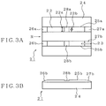
- Fig. 3A is a bottom view showing a configuration of a magnetic head,
- Fig. 3B is a side view showing a configuration of a magnetic head,
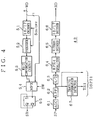
- Fig. 4 is a block diagram illustrating a configuration of a R/W channel IC which constitutes a high recording-density (high-order mode) record/playback system of the floppy disk drive shown in Fig. 1,
- Figs. 5A-5C are diagrams for describing a dc erase process and an intermediate wavelength erase process for a high recording-density (high-order mode) floppy disk,
- Fig. 6 is a diagram showing an overwrite characteristic at the time that a dc erase process is done, and
- Fig. 7 is a diagram for describing improvements in overwrite characteristic based on the dc erase process and the like.
-
- An embodiment of the present invention will hereinafter be described with reference to the accompanying drawings. Fig. 1 shows a
floppy disk drive 10 used as one embodiment of the present invention. Afloppy disk 11 available to thefloppy disk drive 10 is supposed to usefloppy disks 11A and 11B illustrated in Figs. 2A and 2B. Namely, Fig. 2A shows thefloppy disk 11A in which a high recording-density (high-order mode)disk medium 12A having compatibility with already-existing floppy disks and having large or mass recording capacities ranging from about several tens of Mbytes to several hundred Mbytes or greater than or equal to the above Mbytes is held therein. Fig. 2B illustrates the floppy disk 11B in which an already-existing standard recording-density (low-order mode)disk medium 12B having a recording capacity of about 2 Mbytes, for example, is held therein. - In Figs. 2A and 2B, write protectors 15 are respectively used to exhibit a writable state when a hole is closed and a write-protect state when it is open.
HD holes 16 are respectively used to show a so-called 2HD disk having a recording capacity of about 2 Mbytes (upon unformatting) when the hole is open and a disk other than the 2HD disk when the hole is closed. In Fig. 2A, ahole 17 defined in a predetermined position, other than the aforementioned write protectors 15 andHD holes 16 is used to indicate a large-capacity floppy disk whose recording capacity referred to above ranges from about several tens of Mbytes to several hundred Mbytes. - Referring back to Fig. 1, a standard recording-density (low-order mode)
head chip 22 for the existent floppy disk 11B and a high recording-density (high-order mode)head chip 23 for the large-capacity floppy disk 11A are incorporated into amagnetic head 21 for effecting magnetic recording and reproduction or playback on thefloppy disk 1. Figs. 3A and 3B respectively show a configuration of themagnetic head 21. Fig. 3A is a bottom view of themagnetic head 21 as viewed from thefloppy disk 11 side. Fig. 3B is a side view of themagnetic head 21 as viewed from the side below Fig. 3A. - The
magnetic head 21 is constructed such that theaforementioned head chips slider 24. Tworails slider 24 so as to protrude therefrom. Further, the front and rear sides are defined with the disk rotational direction R as the reference,front tapers rails rear tapers 27a and 27b are formed on the rear sides thereof. For example, the angle formed by each of thefront tapers rear tapers 27a and 27b and the disk recording surface is defined as 10°. - Further, the standard recording-density (low-order mode)
head chip 22 is incorporated into therail 25a. Although not described above, thefloppy disk 11 is rotated at the normal speed (e.g., 300 rpm) in the low-order mode. Under the number of the revolutions referred to above, the recording and reproduction of data are performed under the condition where theslider 24 does not float or levitate, and thehead chip 22 and the surface of thefloppy disk 11 are kept in contact with each other. Therefore, a recording-reproducinghead 22a and anerase head 22b of thehead chip 22 are placed in the central position where the contact between thehead chip 22 and the disk surface is brought into the stablest. - Further, the high recording-density (high-order mode)
head chip 23 is incorporated into the rear side of therail 25b. Thehead chip 23 takes a structure such as a MIG (Metal In Gap) head structure, which is capable of increasing a track recording density. Although not described above, thefloppy disk 11 rotates at a high speed (e.g., 3600 rpm) in the high-order mode. Under the number of the revolutions referred to above, floating or levitation pressure resultant from the flow of air is produced so that theslider 24 is levitated from thefloppy disk 11. Owing to the provision of the tworails slider 24 can be stabilized so as to be parallel to the disk surface as viewed in the direction orthogonal to a track direction. - Since the data is not recorded and reproduced stably if the amount of levitation of the
slider 24 varies, the amount of levitation (corresponding to an interval between the disk surface and a gap of the head chip 23) of theslider 24 is now set to a constant value (e.g., 50nm). The amount of levitation thereof is changed according to the widths of therails rails - Basically, the
slots 28a and 28b respectively have the function of decreasing levitation pressure generated due to the flow of air between the bottom face of theslider 24 and the disk surface. The levitation pressure decreases at the positions where theslots 28a and 28b are provided, and the levitation pressure of theslider 24 is also reduced as a whole. Owing to the functions of theslots 28a and 28b, the amount of levitation of theslider 24 on the front side thereof becomes greater than that on the rear side thereof although not shown in the drawing, so that the posture of theslider 24 as viewed from the side thereof is brought into a slightly-inclined state. Thus, when theslider 24 is in the levitated state, the edge of the slider on the rear side thereof is brought to a stable location which serves as a hard-to-change position. Therefore, the high recording-density (high-order mode)head chip 23 is incorporated into the rear side as described above. - Referring back to Fig. 1, the
floppy disk drive 10 has a DSP (digital signal processor) 31 which serves as a controller for performing control on the entire disk drive. Control on the rotation of thefloppy disk 11, control on the movement of themagnetic head 21, control on a high recording-density (high-order mode) record/playback system, control on a standard recording-density (low-order mode) record/playback system, etc. are performed by the DSP 31. The DSP 31 is electrically connected to abus 32. The DSP 31 fetches a program stored in a flash memory 33 electrically connected to thebus 32 and executes control operations in accordance with the program. - The
floppy disk drive 10 has also adisk detector 34 which detects, using the above-describedhole 17 or the like, whether thefloppy disk 11 corresponds to the high recording-density (high-order mode)floppy disk 11A or the standard recording-density (low-order mode) floppy disk 11B. A signal outputted from thedisk detector 34 is supplied to the DSP 31 as a mode signal SMD. The DSP3 performs control on the switching between the rotational speeds of thefloppy disk 11, control on the switching of the record/playback system and control on the switching of an interface in response to the mode signal SMD. - Further, the
floppy disk drive 10 has aspindle motor 35 for rotating thefloppy disk 11 and aspindle motor driver 36 for driving themotor 35. A frequency signal SFG having a frequency corresponding to a rotational speed of thefloppy disk 11, which is obtained from themotor 35, is supplied to the DSP 31 through thespindle motor driver 36. The DSP 31 controls thespindle motor driver 36 by reference to the frequency signal SFG so that the rotational speed of thefloppy disk 11 reaches a predetermined value. - Moreover, the
floppy disk drive 10 includes a voice coil motor (VCM) 38 for moving an arm 37 along a diameter direction of the floppy disk, the arm 37 being used for supporting themagnetic head 21, and aVCM driver 39 for driving thevoice coil motor 38. The DSP 31 controls theVCM driver 39 based on tracking information or the like about themagnetic head 21, which is outputted from a R/W channel IC to be described later, in such a manner that themagnetic head 21 is properly positioned to a target track. - The
floppy disk drive 10 has a high recording-density (high-order mode) record/playback system and a standard recording-density (low-order mode) record/playback system. The high recording-density (high-order mode) record/playback system includes a disk controller 41 for swapping data, status, commands with the host computer side, a DRAM (Dynamic random access memory) 42 which serves as a data buffer, a R/W channel IC 43 for performing a record signal process and a reproduce or playback signal process, a recording amplifier 44 for amplifying a record signal outputted from the R/W channel IC 43 and supplying the amplified signal to thehead chip 23 of themagnetic disk 23, and a reproduce orplayback amplifier 45 for amplifying a signal played back or reproduced by thehead chip 23 and supplying it to the R/W channel IC 43. - The disk controller 41 is electrically connected to the
bus 32. Operations of the disk controller 41 and the R/W channel IC 43 are respectively controlled by the DSP 31. The disk controller 41 is electrically connected to the host computer (not shown) through an EIDE (Extended Intelligent Drive Electronics) interface. Fig. 4 shows the R/W channel IC 43. - The R/W channel IC 43 includes, as a recording system, a 16/17 encoder 51 for performing an encoding process using RLL (Run Length Limited) 16/17 codes, which is used as a digital modulating process, on NRZ (Non Return to Zero) write data WD (8-bit parallel data) supplied from the disk controller 41, and for outputting the processed data as the same NRZ data, a precoder 52 for providing partial response equalization and interference of a reverse characteristic for data (serial data) outputted from the 16/17 encoder 51, and a write compensation circuit 53 for compensating for a phase shift produced in data outputted from the precoder 52 upon reproduction in advance upon recording. The output from the encoder 51 is the RLL and NRZ serial data. Therefore, the output from the encoder 51 is the data within a predetermined frequency range.
- Further, the R/W channel IC 43 has, as the recording system, a
multiplexer 54 for selectively taking out or fetching data (serial data) outputted from the write compensation circuit 53 or data represented in the form of the least significant bit, of the write data WD, and a D flip-flop 55 for toggling themultiplexer 54 so that the output data value of themultiplexer 54 is inverted each time the output data of themultiplexer 54 reaches "1", to thereby obtain a record signal SR. - Now, the 16/17 encoder 51 and the precoder 52 are supplied with an on/off control signal SON/OFF for controlling each of them to an operating state or a non-operating state from the DSP 31. Although each of the encoder 51 and the precoder 52 is normally placed in the operating state in this case, they go into the non-action when a medium wavelength erase is performed as will be described later. Thus, when the encoder 51 and the precoder 52 are respectively placed in the inactive state, the output data of the precoder 52 becomes equal to the write data WD supplied from the disk controller 41.
- The
multiplexer 54 is supplied with a switching control signal SW from the DSP 31. Although themultiplexer 54 is normally placed in a state of taking out the output data of the write compensation circuit 53 in this case, themultiplexer 54 is brought into a state of taking out the data represented in the form of the least significant bit of the write data WD when a dc erase is done as will be described later. - The R/W channel IC 43 also includes, as a reproduction system, an AGC (Automatic Gain Control) circuit 61 for holding the amplitude of the played-back signal SP outputted from the
playback amplifier 45 constant, a low-pass filter 62 for eliminating an unnecessary high-frequency component from a signal outputted from the AGC circuit 61, an A/D converter 63 for converting a signal outputted from the low-pass filter 62 into a digital signal, and an equalizer 64 for effecting waveform equalization of EPR4 (Extended Partial Response class 4) on the output data of the A/D converter 63. - Further, the R/W channel IC 43 has, as the playback system, a Viterbi decoder 65 used as a data discriminator for effecting a 0/1 data identifying process on data outputted from the equalizer 64, and a 16/17 decoder 66 for performing a decoding process using 16/17 codes on data outputted from the Viterbi decoder 65 to thereby obtain a read data RD. Although not described above, the write data WD is equivalent to one subjected to an interleave after having been added with an error correcting code by the disk controller 41. The read data RD is also placed in a state similar to the write data WD and hence subjected to a deinterleave and an error correction by the disk controller 41.
- Moreover, the R/W channel IC 43 has a tracking information detector 67 for detecting tracking information TRI from the output signal of the low-pass filter 62. The tracking information TRI is supplied to the DSP 31. Incidentally, the output signal of the low-pass filter 62 is directly supplied to the DSP 31 where a track number and the like are detected. Further, the DSP 31 controls the
VCM driver 39, based on the tracking information TRI and the track number and the like so that themagnetic head 21 is placed on the target track. - Referring back to Fig. 1, the
floppy disk drive 10 has an FDD controller 47 as the standard recording-density (low-order mode) record/playback system. The FDD controller 47 is electrically connected to the host computer (now shown) through an FDD (Floppy Disk Drive) interface. The FDD controller 47 has the functions of producing a record signal from MFM (Modified Frequency Modulation) data sent from the host computer upon writing and supplying it to thehead chip 22 of themagnetic head 21 and obtaining MFM data from the signal reproduced from thehead chip 22 upon reading and supplying it to the host computer, and the like. - The operation of the
floppy disk drive 10 shown in Fig. 1 will next be explained. A description will be made of the operation thereof at the time that the standard recording-density (low-order mode) floppy disk 11B is mounted to thefloppy disk drive 10 as thefloppy disk 11. In this case, the mode signal SMD supplied to the DSP 31 from thedisk detector 34 exhibits the low-order mode. Therefore, thespindle motor driver 36 is controlled by the DSP 31 based on the frequency signal SFG outputted from thespindle motor 35, so that thefloppy disk 11 is rotated at the normal speed (e.g., 300 rpm). Further, the standard recording-density (low-order mode) record/playback system is put in use under the control of the DSP 31. - In such a state, the MFM data used as write data is supplied to the FDD controller 47 from the host computer through the FDD interface upon writing. The FDD controller 47 outputs a record signal corresponding to the MFM data so as to be supplied to the
head chip 22 of themagnetic head 21, after which the signal is recorded on a target sector on a target track of thefloppy disk 11. Upon reading on the other hand, the signal played back from the target sector on the target track of thefloppy disk 11 by thehead chip 22 is supplied to the FDD controller 47 where the MFM data corresponding to the playedback signal is outputted and supplied to the host computer. In other words, in the low-order mode, the record signal can be recorded with a single process. - A description will be made of the operation of the floppy disk drive at the time that the high recording-density (high-order mode)
floppy disk 11A is mounted to the floppy disk drive as thefloppy disk 11. In this case, the mode signal SMD supplied to the DSP 31 from thedisk detector 34 exhibits the high-order mode. Therefore, thespindle motor driver 36 is controlled by the DSP 31 based on the frequency signal SFG outputted from thespindle motor 35, so that thefloppy disk 11 is rotated at the high speed (e.g., 3600 rpm). Further, the high recording-density (high-order mode) record/playback system is put into use under the control of the DSP 31. - In such a state, writing data is supplied to the disk controller 41 from the host computer through the EIDE interface upon writing and temporarily stored in the DRAM 42. Next, the disk controller 41 effects an error correcting code addition and an interleave on the writing data to produce write data WD.
- When first recording is made to the target sector on the target track of the
floppy disk 11, the disk controller 41 supplies write data WD to the R/W channel IC 43 from which a record signal SR corresponding to the write data WD is outputted and supplied to thehead chip 23 of themagnetic head 21, whereby the signal is recorded on the target sector on the target track while thefloppy disk 11 is being rotated once. - On the other hand, when any data is already recorded on the target sector on the target track of the
floppy disk 11 and overwrite is made to the target sector, recording is done in accordance with the following process steps. In a case of initially recording the data on the target sector, the following process may be available. - 1 ○ A dc erase is first effected on a target sector on a target
track at the first rotation of the
floppy disk 11. In this case, the disk controller 41 supplies write data WD for allowing the least significant bit to be always "0" to the R/W channel IC 43 (see Fig. 4) and themultiplexer 54 of the R/W channel IC 43 is switched so as to output the least significant bit of the write data WD in response to the switching control signal SW outputted from the DSP 31. Thus, themultiplexer 54 outputs only data "0" and hence a record signal SR outputted from the D flip-flop 55 will be fixed to a signal of "0" or "1". Therefore, a dc magnetic field is produced from thehead chip 23 of themagnetic head 21, whereby the dc erase is carried out. Fig. 5A shows a recorded state of afloppy disk 11 before the execution of the dc erase, i.e., in its initial state. In this case, magnetized patterns based on the record signal SR are already formed over a magnetic film 11B used as a recording layer mounted onto adisk substrate 11A. As shown in Fig. 5A, themagnetic pattern 12A of the short wavelength is recorded until a shallow position, themagnetic pattern 12B of the medium wavelength has a deeper recording position than themagnetic pattern 12A of the short wavelength and the magnetic patter 12C of the long wavelength has a deeper recording position than themagnetic pattern 12B of the medium wavelength. The symbol Dh is representative of a recording depth of the magnetic pattern of the long wavelength. Fig. 5B illustrates a recorded state of afloppy disk 11 after having been subjected to the dc erase. In this instance, a magnetized pattern 12D whose direction of magnetization is one direction, is formed over a magnetic film 11B. - 2 ○ An intermediate wavelength erase is next effected on a
target sector on a target track at the second rotation of the
floppy disk 11. In this case, the disk controller 41 supplies write data WD brought to [1010101010 ...] when given as serial data to the R/W channel IC 43. Further, themultiplexer 54 of the R/W channel IC 43 is switched so as to drive the output data of the write compensation circuit 53 in response to the switching control signal SW outputted from the DSP 31. In this case, each of the 16/17 encoder 51 and the precoder 52 is brought to the non-operating state by the on/off control signal SON/OFF outputted from the DSP 31, so that the output data of the precoder 52 becomes equal to the write data WD. Thus, each data is outputted from themultiplexer 54 like "1010101010 ...", and the record signal SR outputted from the D flip-flip 55 is alternately brought to the signal of "0" and the signal of "1" every time when the output from themultiplexer 54 becomes the signal "0". This record signal SR is supplied to thehead chip 23 of themagnetic head 21 and thereafter recorded. The output from themultiplexer 54 is "1111 ..." in the case of the short wavelength and is, for example, "1001001001001 ..." in the case of the long wavelength. As to another example, the frequency of a channel clock of the R/W channel IC 43 may be controlled by the DSP 31 so that the frequency of the record signal SR takes a substantially intermediate frequency in a frequency band of the finally-recorded record signal SR.Fig. 5C shows a recorded state of afloppy disk 11 after having been subjected to an intermediate wavelength erase. In this case, magnetized patterns whose direction of magnetization is alternately reversed and which are constant in length, are formed over a magnetic film 11B. Incidentally, one-direction extending magnetic pattern produced by the dc erase slightly remains in a deeper layer portion of the magnetic film 11B or the rear side of the paper of Fig. 5C. - 3 ○ A record signal SR (updated data) corresponding to
writing data supplied from the host computer is next recorded on
a target sector on a target track at the third rotation of the
floppy disk 11. In this case, the disk controller 41 supplies write data WD produced by effecting an error correcting code addition and an interleave on the writing data to the R/W channel IC 43. Thereafter, the encoder 51 performs encoding using 16/17 codes on the write data WD and the precoder 52 effects a precode thereon. Further, the write compensation circuit 53 performs write compensation on the precoded data and thereafter themultiplexer 54 takes out the output data of the write compensation circuit 53. Thus, the record signal SR corresponding to the writing data supplied from the host computer is obtained from the D flip-flop 55. This record signal SR is supplied to thehead chip 23 of themagnetic head 21 and recorded after it has been amplified by the recording amplifier 44. This forms a magnetic pattern 12E in accordance with the record signal SR. -
- Upon reading on the other hand, the signal reproduced by the
head chip 23 from the target sector on the target track of thefloppy disk 11 is amplified by theplayback amplifier 45, followed by supply to the R/W channel IC 43. Thereafter, the R/W channel IC 43 effects a waveform equalizing operation, a data discriminating operation, a decoding operation using 16/17 codes, etc. on the supplied signal to thereby obtain read data RD. The read data RD is supplied to the disk controller 41 where a deinterleave and an error correction are effected thereon to obtain final read data. This read data is temporarily stored in the DRAM 42 and thereafter supplied to the host computer. - In the present embodiment as has been described above, when the
floppy disk 11 is given as the high recording-density (high-order mode)floppy disk 11A and the overwrite is made to the target sector on the target track of thefloppy disk 11, the dc erase is done by thehead chip 23 of themagnetic disk 21 and the intermediate wavelength erase is further performed. Thereafter, the record signal SR (updated data) corresponding to the writing data is recorded. Thus, a predetermined overwrite characteristic can be ensured by a single head alone. Since the magnetized pattern used as a bed is formed over the magnetic film 11B by the intermediate wavelength erase, the generation of waveform distortion due to one-direction magnetized pattern by the dc erase can be restrained. Incidentally, when only the dc erase is performed and the intermediate wavelength erase is not carried out, for example, when an N pole-based dc erase is done, the excitation of the updated data at an S pole weakens the magnetic field and the excitation of the updated data at an N pole strengthens the magnetic field, whereby waveform distortion is produced. - Fig. 6 shows the relationship between the frequency of an initial record signal and overwrite characteristic [dB]. The overwrite characteristic is representative of a decibel of the un-erased initial record signal that remains after the overwrite operation. A curve a indicates an overwrite characteristic [dB] at the time that a signal of 35 MHz is overwritten. A curve b indicates an overwrite characteristic [dB] at the time that the dc erase is executed. These curves a and b indicate that the desired overwrite characteristic is hard to get as the frequency of the overwrite signal is increased and the frequency of the initial record signal is reduced. On the other hand, a curve c indicates an overwrite characteristic [dB] at the time that the dc erase is done and a signal of 20 MHz is overwritten, and shows the expectation of a few dB of improvement in overwrite characteristic [dB]. Incidentally, the overwrite characteristic [dB] indicates the ratio of a reproduced or played-back signal level of an initial record signal at the time that a signal is recorded in overlap form or a dc erase is executed, to a reproduced signal level of an initial record signal in an initial recorded state.
- Fig. 7 shows improvements in overwrite characteristic at the time that the dc erase and the intermediate wavelength erase are executed as described above. A signal of 2 MHz was recorded as the initial record signal. When the dc erase is effected on the initially-recorded state, the overwrite characteristic [dB] resulted in -24.9 [dB]. Further, when the signal of 20 MHz is recorded in overlap form and the intermediate wavelength erase is carried out, the overwrite characteristic [dB] became -30.8 [dB]. Thereafter, when a signal of 35 MHz is recorded as updated data, the overwrite characteristic [dB] resulted in -30.9 [dB]. When the signal of 35 MHz is overwritten as the updated data without the erase as indicated by the curve a in Fig. 6, the overwrite characteristic [dB] remains at about 15 [dB]. However, the overwrite characteristic [dB] will result in -30.9 dB by the execution of the dc erase and the intermediate wavelength erase as mentioned above. It is thus understood that the overwrite characteristic would be greatly improved.
- Although the aforementioned embodiment shows the case in which the present invention has been applied to the
floppy disk drive 10, it is needless to say that the present invention can be applied even to another drive apparatus using a magnetic disk, such as a hard disk, etc. - According to the present invention, when record data (updated data) is recorded on a magnetic disk, a dc erase is performed and erasing data of a constant frequency is further recorded. Thereafter, the record data is recorded therein. Thus, a requested overwrite characteristic can be ensured and the entire head can be reduced in cost. Since a magnetized pattern used as a bed is formed over a magnetic film owing to the recording of the erasing data, waveform distortion can be restrained from being produced due to the magnetized pattern formed from the dc erase. In addition, the above-discussed advantages can be established only by single head.
- It will be appreciated that the invention is not restricted to the particular embodiments that have been described, and that variations may be made therein without departing from the scope of the invention as defined in the appended claims and equivalents thereof.
Claims (6)
- A magnetic recording apparatus comprising:a magnetic head (21) for applying a magnetic field to a magnetic record medium (11) to form a magnetized pattern on said magnetic record medium (11) and thereby recording record data;conversion means (41) for converting input data into the record data having a predetermined frequency range; andcontrol means for controlling said magnetic head so as to apply a DC magnetic field to a record area of said magnetic record medium (11), to apply to said record area a magnetic field that is inverted at a constant period corresponding to an intermediate frequency within said predetermined frequency range, and to apply to said record area a magnetic field that is inverted in accordance with the record data, when said magnetic head (21) records the record data on the record area.
- A magnetic recording apparatus according to claim 1, wherein said magnetic record medium is a magnetic disk (11).
- A magnetic recording apparatus according to claim 1 or 2, wherein said magnetic head (21) records the information on said magnetic record medium (11) under a condition that said magnetic head floats over said magnetic record medium.
- A magnetic recording apparatus according to anyone of claims 1 to 3 further comprising:selection means for outputting selectively the output from said conversion means or a fixed value; andinversion means for receiving the output from said selection means and inverting the magnetic field when the output from said conversion means becomes a predetermined value different from said fixed value;
wherein said control means (41) controls said magnetic head (21) by controlling said selection means and said inversion means. - A magnetic recording apparatus according to claim 4, wherein said control means (41) controls said selection means to output the fixed value when said magnetic head (21) applies the DC magnetic field to said record medium (11), said control means (41) controls said conversion means to output the record data having the intermediate frequency within the predetermined frequency range when applying the magnetic field that is inverted at the constant period, and said control means (41) controls said conversion means to output the record data that is inverted in accordance with the record data when applying to said record area the magnetic field that is inverted in accordance with the record data.
- A method of recording record data on a predetermined area of a magnetic record medium (11), comprising the steps of:applying (21) a DC magnetic field to the predetermined area;applying (21) to the predetermined area a magnetic field that is inverted at a constant period corresponding to a frequency within a frequency range of the record data; andapplying (21) to the predetermined area a magnetic field that is inverted in accordance with the record data.
Applications Claiming Priority (3)
| Application Number | Priority Date | Filing Date | Title |
|---|---|---|---|
| JP9312098A JPH11144204A (en) | 1997-11-13 | 1997-11-13 | Method for recording data on magnetic disk |
| JP31209897 | 1997-11-13 | ||
| JP312098/97 | 1997-11-13 |
Publications (2)
| Publication Number | Publication Date |
|---|---|
| EP0917130A2 true EP0917130A2 (en) | 1999-05-19 |
| EP0917130A3 EP0917130A3 (en) | 1999-11-17 |
Family
ID=18025224
Family Applications (1)
| Application Number | Title | Priority Date | Filing Date |
|---|---|---|---|
| EP98121602A Withdrawn EP0917130A3 (en) | 1997-11-13 | 1998-11-12 | Apparatus for recording data on magnetic record medium |
Country Status (5)
| Country | Link |
|---|---|
| US (1) | US6204983B1 (en) |
| EP (1) | EP0917130A3 (en) |
| JP (1) | JPH11144204A (en) |
| KR (1) | KR19990045226A (en) |
| CN (1) | CN1124592C (en) |
Families Citing this family (5)
| Publication number | Priority date | Publication date | Assignee | Title |
|---|---|---|---|---|
| KR20100016804A (en) | 2008-08-05 | 2010-02-16 | 삼성전자주식회사 | Method for forming servo track at storage apparatus and data storage apparatus |
| US9111565B2 (en) * | 2009-01-16 | 2015-08-18 | Seagate Technology Llc | Data storage device with both bit patterned and continuous media |
| US9563397B1 (en) | 2010-05-05 | 2017-02-07 | Western Digital Technologies, Inc. | Disk drive using non-volatile cache when garbage collecting log structured writes |
| CN106067304A (en) * | 2016-07-28 | 2016-11-02 | 四川新环佳科技发展有限公司 | A kind of reversible magnetic memory |
| CN111010357B (en) * | 2020-03-09 | 2020-06-16 | 中国人民解放军国防科技大学 | Data ferrying method and device based on HDD hard disk |
Citations (6)
| Publication number | Priority date | Publication date | Assignee | Title |
|---|---|---|---|---|
| JPS61287008A (en) * | 1985-06-12 | 1986-12-17 | Alps Electric Co Ltd | Recording and reproducing method for magnetic disk device |
| JPS6297106A (en) * | 1985-10-23 | 1987-05-06 | Mitsubishi Electric Corp | Writing circuit for magnetic recording device |
| JPH01263901A (en) * | 1988-04-14 | 1989-10-20 | Yamaha Corp | Vertical magnetic recording method |
| US4901169A (en) * | 1987-02-27 | 1990-02-13 | Kabushiki Kaisha Toshiba | Data recording apparatus able to accurately access a floppy disk regardless of recording density |
| US5053893A (en) * | 1984-07-16 | 1991-10-01 | Fuji Photo Film Co., Ltd. | Method of and device for demagnetizing magnetic recording medium |
| US5060089A (en) * | 1990-08-22 | 1991-10-22 | Storage Technology Corporation | Data write pulse compensator circuit |
Family Cites Families (2)
| Publication number | Priority date | Publication date | Assignee | Title |
|---|---|---|---|---|
| US4532562A (en) | 1981-04-24 | 1985-07-30 | Iomega Corporation | Servo control of seek operation in magnetic disk drive |
| US4802050A (en) | 1986-02-21 | 1989-01-31 | Brother Kogyo Kabushiki Kaisha | Magnetic recording medium |
-
1997
- 1997-11-13 JP JP9312098A patent/JPH11144204A/en active Pending
-
1998
- 1998-10-19 US US09/175,118 patent/US6204983B1/en not_active Expired - Fee Related
- 1998-11-12 EP EP98121602A patent/EP0917130A3/en not_active Withdrawn
- 1998-11-12 KR KR1019980048390A patent/KR19990045226A/en not_active Application Discontinuation
- 1998-11-13 CN CN98124193A patent/CN1124592C/en not_active Expired - Fee Related
Patent Citations (6)
| Publication number | Priority date | Publication date | Assignee | Title |
|---|---|---|---|---|
| US5053893A (en) * | 1984-07-16 | 1991-10-01 | Fuji Photo Film Co., Ltd. | Method of and device for demagnetizing magnetic recording medium |
| JPS61287008A (en) * | 1985-06-12 | 1986-12-17 | Alps Electric Co Ltd | Recording and reproducing method for magnetic disk device |
| JPS6297106A (en) * | 1985-10-23 | 1987-05-06 | Mitsubishi Electric Corp | Writing circuit for magnetic recording device |
| US4901169A (en) * | 1987-02-27 | 1990-02-13 | Kabushiki Kaisha Toshiba | Data recording apparatus able to accurately access a floppy disk regardless of recording density |
| JPH01263901A (en) * | 1988-04-14 | 1989-10-20 | Yamaha Corp | Vertical magnetic recording method |
| US5060089A (en) * | 1990-08-22 | 1991-10-22 | Storage Technology Corporation | Data write pulse compensator circuit |
Non-Patent Citations (3)
| Title |
|---|
| PATENT ABSTRACTS OF JAPAN vol. 011, no. 151 (P-576), 16 May 1987 (1987-05-16) & JP 61 287008 A (ALPS ELECTRIC CO LTD), 17 December 1986 (1986-12-17) * |
| PATENT ABSTRACTS OF JAPAN vol. 011, no. 305 (P-623), 6 October 1987 (1987-10-06) & JP 62 097106 A (MITSUBISHI ELECTRIC CORP), 6 May 1987 (1987-05-06) * |
| PATENT ABSTRACTS OF JAPAN vol. 014, no. 021 (P-990), 17 January 1990 (1990-01-17) & JP 01 263901 A (YAMAHA CORP), 20 October 1989 (1989-10-20) * |
Also Published As
| Publication number | Publication date |
|---|---|
| KR19990045226A (en) | 1999-06-25 |
| CN1124592C (en) | 2003-10-15 |
| EP0917130A3 (en) | 1999-11-17 |
| CN1217526A (en) | 1999-05-26 |
| JPH11144204A (en) | 1999-05-28 |
| US6204983B1 (en) | 2001-03-20 |
Similar Documents
| Publication | Publication Date | Title |
|---|---|---|
| US7075743B2 (en) | Method of servo writing for magnetic recording system, magnetic recording system | |
| US6094318A (en) | Method and apparatus for controlling data write operation according to flying height of transducer head | |
| US20060139788A1 (en) | Method, medium, and apparatus recording a servo pattern | |
| US7952825B2 (en) | Method and apparatus adjusting reference clock frequency and disk drive using same | |
| US6768605B2 (en) | Flexible disk device, disk formatting method, and recording/reproducing method | |
| US7450328B2 (en) | Method for recording bursts on a disk and related apparatus | |
| US7605993B2 (en) | Write current boosted head amplifier | |
| US5754354A (en) | Magnetic disk drive unit with complex magnetic head of variable reading width | |
| JP3645505B2 (en) | Disk storage device and read method applied to the same | |
| US7944641B2 (en) | Overshoot duration range selection in a hard disk drive | |
| US6130791A (en) | Magnetic disk drive having read channel in which low-frequency cutoff is set relatively high to cope with thermal asperity | |
| US6204983B1 (en) | Apparatus for recording data on magnetic record medium | |
| US7570446B2 (en) | Disk drive with improved format efficiency and control method thereof | |
| JP2001189062A (en) | Disk storage device and servo data write-in method | |
| US8049986B2 (en) | Control method for magnetic disk device, magnetic disk device, and magnetic disk | |
| US6388839B2 (en) | Magnetic head device and recording medium drive | |
| KR100268483B1 (en) | Methodfor recording servo information of magnetic recording media | |
| JP2000123305A (en) | Disk drive device | |
| JPH11232812A (en) | Magnetic disk storage device | |
| JP2003346303A (en) | Rotating magnetic head type recording and reproducing device, and recording and reproducing method | |
| JPH1091930A (en) | Magnetic disk device | |
| JPH03266214A (en) | Magnetic recording and reproducing device | |
| JPH09320007A (en) | Signal system for flexible disk drive commonly used for high density and normal density | |
| JP2000322852A (en) | Magnetic recording and playback apparatus | |
| JP2000048512A (en) | Magnetic head device and disk drive |
Legal Events
| Date | Code | Title | Description |
|---|---|---|---|
| PUAI | Public reference made under article 153(3) epc to a published international application that has entered the european phase |
Free format text: ORIGINAL CODE: 0009012 |
|
| AK | Designated contracting states |
Kind code of ref document: A2 Designated state(s): DE FR GB IT NL |
|
| AX | Request for extension of the european patent |
Free format text: AL;LT;LV;MK;RO;SI |
|
| PUAL | Search report despatched |
Free format text: ORIGINAL CODE: 0009013 |
|
| AK | Designated contracting states |
Kind code of ref document: A3 Designated state(s): AT BE CH CY DE DK ES FI FR GB GR IE IT LI LU MC NL PT SE |
|
| AX | Request for extension of the european patent |
Free format text: AL;LT;LV;MK;RO;SI |
|
| RIC1 | Information provided on ipc code assigned before grant |
Free format text: 6G 11B 5/00 A, 6G 11B 5/012 B, 6G 11B 5/02 B, 6G 11B 5/09 B, 6G 11B 5/024 B |
|
| 17P | Request for examination filed |
Effective date: 20000516 |
|
| AKX | Designation fees paid |
Free format text: DE FR GB IT NL |
|
| STAA | Information on the status of an ep patent application or granted ep patent |
Free format text: STATUS: THE APPLICATION HAS BEEN WITHDRAWN |
|
| 18W | Application withdrawn |
Withdrawal date: 20021007 |