EP0917080B1 - Method of locating highly variable brightness or colour regions in an image - Google Patents
Method of locating highly variable brightness or colour regions in an image Download PDFInfo
- Publication number
- EP0917080B1 EP0917080B1 EP97830607A EP97830607A EP0917080B1 EP 0917080 B1 EP0917080 B1 EP 0917080B1 EP 97830607 A EP97830607 A EP 97830607A EP 97830607 A EP97830607 A EP 97830607A EP 0917080 B1 EP0917080 B1 EP 0917080B1
- Authority
- EP
- European Patent Office
- Prior art keywords
- image
- subimages
- logic value
- region
- block
- Prior art date
- Legal status (The legal status is an assumption and is not a legal conclusion. Google has not performed a legal analysis and makes no representation as to the accuracy of the status listed.)
- Expired - Lifetime
Links
Images


Classifications
-
- G—PHYSICS
- G06—COMPUTING; CALCULATING OR COUNTING
- G06K—GRAPHICAL DATA READING; PRESENTATION OF DATA; RECORD CARRIERS; HANDLING RECORD CARRIERS
- G06K7/00—Methods or arrangements for sensing record carriers, e.g. for reading patterns
- G06K7/10—Methods or arrangements for sensing record carriers, e.g. for reading patterns by electromagnetic radiation, e.g. optical sensing; by corpuscular radiation
- G06K7/10544—Methods or arrangements for sensing record carriers, e.g. for reading patterns by electromagnetic radiation, e.g. optical sensing; by corpuscular radiation by scanning of the records by radiation in the optical part of the electromagnetic spectrum
- G06K7/10821—Methods or arrangements for sensing record carriers, e.g. for reading patterns by electromagnetic radiation, e.g. optical sensing; by corpuscular radiation by scanning of the records by radiation in the optical part of the electromagnetic spectrum further details of bar or optical code scanning devices
- G06K7/1092—Methods or arrangements for sensing record carriers, e.g. for reading patterns by electromagnetic radiation, e.g. optical sensing; by corpuscular radiation by scanning of the records by radiation in the optical part of the electromagnetic spectrum further details of bar or optical code scanning devices sensing by means of TV-scanning
-
- G—PHYSICS
- G06—COMPUTING; CALCULATING OR COUNTING
- G06K—GRAPHICAL DATA READING; PRESENTATION OF DATA; RECORD CARRIERS; HANDLING RECORD CARRIERS
- G06K7/00—Methods or arrangements for sensing record carriers, e.g. for reading patterns
- G06K7/10—Methods or arrangements for sensing record carriers, e.g. for reading patterns by electromagnetic radiation, e.g. optical sensing; by corpuscular radiation
- G06K7/10544—Methods or arrangements for sensing record carriers, e.g. for reading patterns by electromagnetic radiation, e.g. optical sensing; by corpuscular radiation by scanning of the records by radiation in the optical part of the electromagnetic spectrum
- G06K7/10821—Methods or arrangements for sensing record carriers, e.g. for reading patterns by electromagnetic radiation, e.g. optical sensing; by corpuscular radiation by scanning of the records by radiation in the optical part of the electromagnetic spectrum further details of bar or optical code scanning devices
- G06K7/1093—Methods or arrangements for sensing record carriers, e.g. for reading patterns by electromagnetic radiation, e.g. optical sensing; by corpuscular radiation by scanning of the records by radiation in the optical part of the electromagnetic spectrum further details of bar or optical code scanning devices sensing, after transfer of the image of the data-field to an intermediate store, e.g. storage with cathode ray tube
-
- G—PHYSICS
- G06—COMPUTING; CALCULATING OR COUNTING
- G06K—GRAPHICAL DATA READING; PRESENTATION OF DATA; RECORD CARRIERS; HANDLING RECORD CARRIERS
- G06K7/00—Methods or arrangements for sensing record carriers, e.g. for reading patterns
- G06K7/10—Methods or arrangements for sensing record carriers, e.g. for reading patterns by electromagnetic radiation, e.g. optical sensing; by corpuscular radiation
- G06K7/14—Methods or arrangements for sensing record carriers, e.g. for reading patterns by electromagnetic radiation, e.g. optical sensing; by corpuscular radiation using light without selection of wavelength, e.g. sensing reflected white light
- G06K7/1404—Methods for optical code recognition
- G06K7/1439—Methods for optical code recognition including a method step for retrieval of the optical code
- G06K7/1443—Methods for optical code recognition including a method step for retrieval of the optical code locating of the code in an image
Definitions
- the present invention relates to a method of locating highly variable brightness or colour regions in an image.
- optical codes e.g. bar codes, two-dimensional codes, etc.
- optical codes are defined by a number of two-dimensional elements of given shape, of different colours (e.g. black/white or variously coloured elements), and arranged in a precise geometric order.
- Some known locating systems use optical sensors (in particular television cameras) for picking up a two-dimensional image of the objects and selecting from the image an image portion corresponding to the optical code. Such systems also read the code contained in the selected image portion and extract the alphanumeric information of the code.
- the image picked up by the camera normally includes a background in which are distinguishable a number of relevant regions varying considerably in brightness or colour and which correspond to optical code images, to graphically defined portions (e.g. tables or matrixes, labels and geometrically defined structures) and to alphanumeric signs automatically or manually impressed and arranged in orderly manner (e.g. aligned in rows).
- a background in which are distinguishable a number of relevant regions varying considerably in brightness or colour and which correspond to optical code images, to graphically defined portions (e.g. tables or matrixes, labels and geometrically defined structures) and to alphanumeric signs automatically or manually impressed and arranged in orderly manner (e.g. aligned in rows).
- Aim of the present invention is to provide a method of locating, in an image of the above said type, any relevant highly variable brightness or colour region, regardless of whether an optical code is included in the image or not. More specifically, aim of the present invention is to eliminate from the image any relevant specifically ordered regions (normally corresponding to optical code images or geometrically defined structures), by locating relevant regions of a different order from the relevant specifically ordered regions.
- a method of locating highly variable brightness or colour regions in an acquired image wherein said image has a number of relevant regions, including : at least one region specifically ordered as to structure and/or colour, characterized by said image comprising at least one highly variable brightness or colour region; the order level of said highly variable brightness or colour region differing from the order of the specifically ordered region and said method comprising the steps of: performing a first processing step of said image to generate a first intermediate binary image representing the acquired image divided into a number of first subimages, each having a first logic value if corresponding to a detected specifically ordered region, and a second logic value if corresponding to a region of the image other than said specifically ordered region; performing a second processing step of said acquired image to generate a second intermediate binary image representing the image divided into a number of second subimages, each having a first logic value if corresponding to a detected said specifically ordered region or a detected highly variable brighness or colour region, and a second logic value otherwise; subtracting the first intermediate binary
- said first processing step of said acquired image comprises the steps of: calculating a number of gradient vectors for a number of elementary images into which said image is divided; determining significant gradients of an amplitude above a threshold value; assigning said first logic value to the first subimages containing significant gradient vectors with said predetermined orientation; assigning said second logic value to the first subimages containing significant gradient vectors with an orientation other than said predetermined orientation; and assigning said second logic value to the first subimages containing nonsignificant gradient vectors; said second processing step of said acquired image comprises the steps of: calculating a number of gradient vectors for a number of elementary images into which said image is divided; determining significant gradients of an amplitude above a threshold value; assigning said first logic value to the second subimages containing significant gradient vectors; assigning said second logic value to the second subimages containing nonsignificant gradient vectors.
- Number 1 in Figure 1 indicates as a whole an automatic optical code reading device comprising a read head 5 facing a conveyor belt 6 to scan objects 7 laying on conveyor belt 6 and traveling in a straight horizontal direction D.
- Each object 7 comprises, on a face 7a facing read head 5, a scanning region comprising a number of relevant regions ( Figure 2).
- the scanning region may comprise, in general, a preferably flat surface defining a background BK (preferably, but not necessarily, of uniform colour) and a number of relevant regions Z distinguishable from the background by structure and colour and containing information or a structure for the insertion of information.
- the relevant regions may comprise:
- Examples of two-dimensional optical codes are the so-called ID-CODE codes defined by black or white square unit elements and MAXICODE codes defined by black or white hexagonal unit elements.
- the relevant regions comprise, in general:
- the specifically ordered region Zc is a region containing bar codes, each defined by elements parallel to one direction d and the highly variable brightness region is a region (Za) containing a two-dimensional optical code, i.e. defined by elements with orientations not coinciding with the one orientation of the bar code.
- the specifically ordered region Zc also includes retangular frame structures.
- Device 1 comprises an electronic control and processing unit 12 cooperating with read head 5.
- the device also comprises a sensor 14 located along conveyor belt 6 to determine the height of objects 7 traveling along the belt; a sensor 15 to determine the presence of objects 7 close to read head 5 and a speed sensor 16 to determine the traveling speed of the belt (and therefore of the conveyed objects) with respect to read head 5.
- Device 1 also comprises a lighting device 17 for lighting the section of the belt detected by read head 5.
- read head 5 comprises a linear (e.g. CCD) television camera 20 for scanning a line 6a of the belt (continuously or when enabled by sensors 14, 15, 16) and a circuit 22 for processing the output signals of camera 20.
- Circuit 22 comprises a filter 24 input-connected to the output of camera 20; a memory 26 input-connected to the output of camera 20 and for storing images and one (or more) programmable data processing unit (DSP - digital signal processor) 28 cooperating with filter 24 and memory 26.
- DSP programmable data processing unit
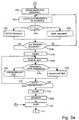
- Figures 3 and 3a show a flow chart of the operating cycle of processing circuit 22.
- a start block 100 goes on to a block 110, in which the lines 6a scanned by camera 20 are composed electronically to form a two-dimensional image (memorized in memory 26) of conveyor belt 6 and/or objects 7.
- a digital image I ( Figure 2) is thus formed, comprising a matrix of pixels, each characterized by a number defining its grey level.
- the acquired digital image I may comprise the image of one or more objects 7, and in which are visible the relevant regions Z and background BK.
- Block 110 is followed by a block 120, in which acquired digital image I is divided into a number of elementary images (windows) If, each comprising a predetermined N number of pixels.
- windows If may comprise four pixels, as shown in Figure 4.
- Block 120 is followed by a block 130, which calculates the brightness gradient vector G of each window If of image I.
- Block 130 is followed by a block 140, which compares the amplitude of each calculated gradient vector with a threshold value Glim1 established during initialization. If the amplitude of the gradient vector is below the threshold, block 140 is followed by a block 150, which cancels the gradient vector as being nonsignificant by representing slow variations in brightness. Conversely (block 160 following block 140), the calculated gradient vector is considered significant by representing rapid variations in brightness, and is kept for subsequent processing.
- Block 160 is followed by a block 170, which effects a transformation of each selected calculated gradient vector to determine at least one given direction and given side for the specifically ordered region which direction and side are assigned to all the calculated gradients.
- the transformation operator in block 170 is capable of passing from gradient space (defined by amplitude, direction and side) to direction space (only defined by amplitude and direction), so that, when transformed, two gradients with the same amplitude and direction but opposite sides are mapped in the same vector in the directions space.
- One possible transformation is that whereby the gradient vectors angles are multiplied by a factor equal to the number of sides of the unit element forming the optical code in specifically ordered region Zc.
- the transformation is effected by doubling the angle ⁇ of each gradient vector.
- Block 170 is followed by a block 200 in which each gradient vector G transformed in block 170 is approximated to the nearest of a series of reference vectors (gradient vector quantization). More specifically, the reference vectors may comprise four first unit vectors V 1 , V 2 , V 3 , V 4 perpendicular to one another, and four second vectors T 1 , T 2 , T 3 , T 4 perpendicular to one another and forming a 45° angle with the first vectors ( Figure 5).
- Block 200 is followed by a block 210, which determines whether examination (and calculation of the gradient vector) of windows If defined in block 120 is terminated. In the event of a negative response (windows If still being examined), block 210 goes back to block 130 to calculate a further gradient vector. Conversely (examination of windows If terminated), block 210 goes on to a block 215.
- Block 215 groups the quantized gradients of image I into a number of subsets (subimages) or so-called tiles Ip, which are obtained by dividing the acquired image I into a number of subimages (tiles) Ip, each comprising a number of windows If.
- tiles Ip may be defined by a hundred pixels of the original image I and so comprise, in the embodiment shown, twenty-five windows If (each window comprises four pixels).
- the next processing step provides for determining which regions in the original digitized image I contain gradient vectors corresponding to specifically ordered region Zc (the highly variable brightness regions are not considered).
- Block 215 is followed by a block 220, which calculates the vectorial sum of the gradient vectors processed in blocks 170, 200 and relating to a subimage Ip, i.e. the transformed and quantized gradient vectors of the various windows If are composed to generate a sum gradient vector Gs associated with the currently selected tile Ip.
- Block 220 is followed by a block 230, in which the sum gradient vector Gs is compared with threshold values ( Figure 6). If the sum gradient vector Gs is above the threshold values, block 230 goes on to a block 240. Conversely (sum gradient vector Gs below the threshold values), block 230 goes on to a block 250.
- the threshold values may be represented, for example, by the sides of a square Q ( Figure 6), so that, if one end of sum gradient vector Gs lies within the perimeter of square Q, block 230 goes on to block 250. Conversely (end of sum gradient vector Gs outside the perimeter of square Q), block 230 goes on to block 240.
- the situation determined in block 240 is that in which the value of the sum gradient vector in the space of directions is above the threshold; in which case, the respective tile Ip is considered significant by comprising a sufficient number of gradient vectors of significant amplitude and substantially the same direction (specifically ordered region detected - possible presence of an optical code or rectangular frame structure).
- the selected tile Ip is therefore assigned a first logic value (in particular, a logic "1") indicating tile Ip is to be considered as relating to a specifically ordered region.
- the situation determined in block 250 is that in which the value of sum gradient vector Gs in the space of directions is below the threshold; in which case, the respective tile is considered nonsignificant by comprising an insufficient number of gradients of significant amplitude and substantially the same direction.
- the selected tile is therefore assigned a second logic value (in particular, a logic "0") indicating tile Ip is to be considered nonsignificant and corresponding to an image region other than the specifically ordered region, i.e. background BK, to a portion of the image with no significant variation in brightness or colour, or to a highly variable brightness portion of the image of an order other than that of the specifically ordered region.
- Blocks 240, 250 are followed by a block 260, which determines whether all the tiles Ip in image I have been examined. In the event of a negative response (image still being examined), block 260 goes back to block 220 to examine a further tile Ip. Conversely (examination of image I terminated), block 260 goes on to a block 270.
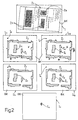
- the output of block 260 is a first intermediate binary image Ir1 ( Figure 2) representing image I divided into a number of contiguous tiles Ip, each having a logic value "1" (significant, “black” tile) if likely to correspond to a specifically ordered region Zc (presence of an optical code or rectangular frame structure), or a logic value "0" (nonsignificant, "white” tile) if corresponding to the background image or to a highly variable brightness region Za of an order other than that of specifically ordered region Zc.
- the elementary unit representing first intermediate binary image Ir1 is the same size as tile Ip. In other words, tiles Ip constitute the pixels of image Ir1.
- First intermediate binary image Ir1 is supplied to a block 270 downstream from block 260 which (in known manner) performs a filtering process to reduce the effects of acquisition noise and eliminate any "dirty" regions in the image.
- the operations performed in block 270 provide for eliminating any short or narrow groups of significant tiles.
- Block 270 may also eliminate any apparently significant spurious regions of image Ir1 (i.e. defined by "black" tiles) not actually corresponding to the specifically ordered region (to the bar code image, in the example shown). Block 270 provides in known manner for automatically recognizing such spurious regions and for selecting the regions corresponding to the bar code by means of an automatic pattern recognition process for discerning spurious regions.
- Figure 2 shows image Ir1 before (top) and after (bottom) processing by block 270. A comparison of the two images clearly shows elimination of the spurious regions (crossed-out tiles) .
- the output of block 270 is therefore an image (first intermediate binary image Ir1) defined by a number of tiles Ip, which may have a first or second state:
- Image Ir1 processed in block 270 is memorized in the next block 280.
- the image acquired in block 110 is also supplied to a block 120a ( Figure 3a), which, like block 120, divides the acquired digital image I into a number of elementary images (windows) If, each comprising a predetermined N number of pixels (e.g. four).
- the windows If in block 120a are the same size as in corresponding block 120.
- Block 120a is followed by a block 130a, which calculates the brightness gradient G of each window If of image I.
- Block 130a is followed by a block 140a, which compares the amplitude of each calculated gradient with a threshold value Glim2 established during initialization. If the amplitude of the gradient is below threshold Glim2, block 140a is followed by a block 150a, which cancels the gradient as being nonsignificant by representing slow variations in brightness. Conversely (block 160a following block 140a), the calculated gradient is considered significant by representing rapid variations in brightness, and is kept for subsequent processing.
- Block 160a is followed by a block 210a, which determines whether examination (and calculation of the gradients) of windows If defined in block 120a is terminated. In the event of a negative response (windows If still being examined), block 210a goes back to block 130a to calculate a further gradient. Conversely (examination of windows If terminated), block 210a goes on to a block 215a.
- Block 215a groups the gradients of image I into a number of subsets (subimages) or so-called tiles Ip, which are the same size as tiles Ip in block 215 and are obtained by dividing the acquired image I into a number of subimages (tiles) Ip, each comprising a number of windows If.
- tiles Ip may be defined by a hundred pixels of the original image I, and so comprise, in the embodiment shown, twenty-five windows If (each window comprises four pixels).
- the next processing step provides for determining which regions in the original digitized image I contain a large number of gradients, regardless of the direction, and so correspond to specifically ordered regions and to highly variable brightness regions of an order other than that of the specifically ordered regions.
- Block 215a is followed by a block 220a, which calculates the scalar sum of the gradients kept by block 160a and relating to a subimage Ip, i.e. the gradients of the various windows If are composed to generate a sum gradient Gs associated with the currently selected tile Ip.
- Block 220a is followed by a block 230a, in which the sum gradient Gs is compared with threshold values. If the sum gradient Gs is above the threshold values, block 230a goes on to a block 240a. Conversely (sum gradient Gs below the threshold values), block 230a goes on to a block 250a.
- the situation determined in block 240a is that in which the value of the sum gradient is above the threshold; in which case, the respective tile Ip is considered significant by comprising a sufficient number of gradients of significant amplitude (possible presence of a specifically ordered region corresponding to the image of an optical code and/or of a highly variable brightness or colour region).
- the selected tile Ip is therefore assigned a first logic value (in particular, a logic "1") indicating tile Ip is to be considered as relating to a specifically ordered region or to a highly variable brightness or colour region.
- the situation determined in block 250a is that in which the value of sum gradient Gs in the space of directions is below the threshold; in which case, the respective tile is considered nonsignificant by comprising an insufficient number of gradients of significant amplitude.
- the selected tile is therefore assigned a second logic value (in particular, a logic "0") indicating tile Ip is to be considered nonsignificant and preferably corresponding to the background or at any rate to a region with no significant variation in brightness or colour.
- Blocks 240a, 250a are followed by a block 260a, which determines whether all the tiles Ip in image I have been examined. In the event of a negative response (image still being examined), block 260a goes back to block 220a to examine a further tile Ip. Conversely (examination of image I terminated), block 260a goes on to a block 270a.
- the output of block 260a is a second intermediate binary image Ir2 ( Figure 2) representing image I divided into a number of contiguous tiles Ip, each having a logic value "1" (significant, "black” tile) if likely to correspond to a specifically ordered region and/or to a highly variable brightness region, or a logic value "0" (nonsignificant, "white” tile) if corresponding to the background image or to a region with no significant variation in brightness or colour.
- image Ir2 is processed to eliminate any spurious regions (block 270a following block 260a), and the output of block 270a is supplied to a block 280a.
- Figure 2 shows image Ir2 before (top) and after (bottom) processing by block 270a. A comparison of the two images clearly shows elimination of the spurious regions (crossed-out tiles).
- the elementary unit representing second intermediate binary image Ir2 is the same size as that representing first intermediate binary image Ir1.
- the output of block 270a is therefore an image (second intermediate binary image Ir2) defined by a number of tiles Ip, which may have a first or second state:
- the first and second intermediate binary images Ir1 and Ir2 memorized in respective blocks 280 and 280a are supplied to a masking block 300 for subtracting image Ir1 (according to the set theory) from image Ir2.
- second intermediate binary image Ir2 comprises significant tiles both at specifically ordered regions and highly variable brightness or colour regions of any order; while first intermediate binary image Ir1 comprises significant tiles at specifically ordered regions only.
- image Ir1 is subtracted from image Ir2, the contributions of the specifically ordered regions of the two images cancel each other out, so that an output image Iu is generated comprising only the highly variable brightness or colour regions of an order other than that of the specifically ordered regions.
- the size of the tiles in fact, is the same, and the specifically ordered regions occupy the same positions in both images Ir1 and Ir2, by virtue of the process described to acquire images Ir1, Ir2 working on the same original image, and using algorithms (blocks 120, 120a and 215, 215a) effecting the same divisions.
- An output image Iu is therefore generated which only comprises significant tiles in the highly variable brightness or colour regions of an order other than that of the specifically ordered regions, i.e. the specifically ordered regions are eliminated.
- At least one relevant highly variable brightness or colour region containing information is located.
- the output image Iu processed in block 300 is then supplied for subsequent processing to a block 310, which operates on the regions of image 'I corresponding to significant tiles.
- the advantages of the present invention are clear from the foregoing description.
- the method described in fact provides for locating highly variable brightness or colour regions in an image by eliminating the specifically ordered regions.
- the main adjustable parameters are the following:
- the selected tile size is approximately half the apparent minimum size of the code (i.e. the size of the code measured in image I), so as to ensure the code image contains at least one whole tile.
Abstract
Description
- The present invention relates to a method of locating highly variable brightness or colour regions in an image.
- Systems are known for locating optical codes applied to objects moving along conveying devices (e.g. conveyor belts), and for determining the presence and space disposition of the code. As is known optical codes (e.g. bar codes, two-dimensional codes, etc.) are defined by a number of two-dimensional elements of given shape, of different colours (e.g. black/white or variously coloured elements), and arranged in a precise geometric order.
- Some known locating systems use optical sensors (in particular television cameras) for picking up a two-dimensional image of the objects and selecting from the image an image portion corresponding to the optical code. Such systems also read the code contained in the selected image portion and extract the alphanumeric information of the code.
- The image picked up by the camera normally includes a background in which are distinguishable a number of relevant regions varying considerably in brightness or colour and which correspond to optical code images, to graphically defined portions (e.g. tables or matrixes, labels and geometrically defined structures) and to alphanumeric signs automatically or manually impressed and arranged in orderly manner (e.g. aligned in rows).
- Other known systems provide solely for locating in the image any specifically ordered regions corresponding, for example, to an optical code. In particular, systems are known for extracting from the image a subimage corresponding to the optical code. Such a system is disclosed in the document US-A-5 120 940.
- Aim of the present invention is to provide a method of locating, in an image of the above said type, any relevant highly variable brightness or colour region, regardless of whether an optical code is included in the image or not. More specifically, aim of the present invention is to eliminate from the image any relevant specifically ordered regions (normally corresponding to optical code images or geometrically defined structures), by locating relevant regions of a different order from the relevant specifically ordered regions.
- According to the present invention, there is provided a method of locating highly variable brightness or colour regions in an acquired image, wherein said image has a number of relevant regions, including : at least one region specifically ordered as to structure and/or colour, characterized by said image comprising at least one highly variable brightness or colour region; the order level of said highly variable brightness or colour region differing from the order of the specifically ordered region and said method comprising the steps of: performing a first processing step of said image to generate a first intermediate binary image representing the acquired image divided into a number of first subimages, each having a first logic value if corresponding to a detected specifically ordered region, and a second logic value if corresponding to a region of the image other than said specifically ordered region; performing a second processing step of said acquired image to generate a second intermediate binary image representing the image divided into a number of second subimages, each having a first logic value if corresponding to a detected said specifically ordered region or a detected highly variable brighness or colour region, and a second logic value otherwise; subtracting the first intermediate binary image from the second intermediate binary image to generate an output binary image defined by a number of subimages having said first logic value only at said highly variable brightness or colour regions of an order other than that of the specifically ordered regions, and said second logic value elsewhere.
- More specifically, said first processing step of said acquired image comprises the steps of: calculating a number of gradient vectors for a number of elementary images into which said image is divided; determining significant gradients of an amplitude above a threshold value; assigning said first logic value to the first subimages containing significant gradient vectors with said predetermined orientation; assigning said second logic value to the first subimages containing significant gradient vectors with an orientation other than said predetermined orientation; and assigning said second logic value to the first subimages containing nonsignificant gradient vectors; said second processing step of said acquired image comprises the steps of: calculating a number of gradient vectors for a number of elementary images into which said image is divided; determining significant gradients of an amplitude above a threshold value; assigning said first logic value to the second subimages containing significant gradient vectors; assigning said second logic value to the second subimages containing nonsignificant gradient vectors.
- A non-limiting embodiment of the present invention will be described by way of example with reference to the accompanying drawings, in which:
- Figure 1 shows, schematically, an automatic optical code reading device implementing the method according to the present invention;
- Figure 2 shows a series of images processed according to the method of the present invention;
- Figures 3 and 3a show a logic operating diagram of the method according to the present invention;
- Figures 4, 5, 6 show examples of operating steps according to the method of the present invention.
-
- Number 1 in Figure 1 indicates as a whole an automatic optical code reading device comprising a
read head 5 facing a conveyor belt 6 to scanobjects 7 laying on conveyor belt 6 and traveling in a straight horizontal direction D. Eachobject 7 comprises, on aface 7a facing readhead 5, a scanning region comprising a number of relevant regions (Figure 2). The scanning region may comprise, in general, a preferably flat surface defining a background BK (preferably, but not necessarily, of uniform colour) and a number of relevant regions Z distinguishable from the background by structure and colour and containing information or a structure for the insertion of information. For example, the relevant regions may comprise: - portions delimited by graphic signs, such as tables or matrixes, labels and geometrically defined structures in general;
- automatically impressed alphanumeric signs (printed or typed by a typewriter or a printer);
- manually impressed alphanumeric signs;
- photographs;
- optical codes defined by a number of graphic signs whereby information is coded in the form of a sequence of black and white or variously coloured regions extending in one or more directions. Optical codes comprise:
- bar codes defined by a number of differently coloured alternating straight elements (black bars and white spaces) adjacent to one another and parallel to one direction;
- two-dimensional codes defined by a number of differently coloured elements of a given shape, adjacent to one another and extending in two (or more) directions; and
- colour codes.
- Examples of two-dimensional optical codes are the so-called ID-CODE codes defined by black or white square unit elements and MAXICODE codes defined by black or white hexagonal unit elements.
- In the embodiment shown, the relevant regions comprise, in general:
- at least one specifically ordered region Zc containing an optical code defined by elements, all with a predetermined orientation, in particular elements parallel to one direction as in the case of a bar code; and
- at least one highly variable brightness region Za containing a number of elements with a certain order level (e.g. a MAXICODE), which order level, however, does not correspond with the order of the specifically ordered region Zc.
-
- In the embodiment shown, the specifically ordered region Zc is a region containing bar codes, each defined by elements parallel to one direction d and the highly variable brightness region is a region (Za) containing a two-dimensional optical code, i.e. defined by elements with orientations not coinciding with the one orientation of the bar code. The specifically ordered region Zc also includes retangular frame structures.
- Device 1 comprises an electronic control and
processing unit 12 cooperating with readhead 5. - The device also comprises a
sensor 14 located along conveyor belt 6 to determine the height ofobjects 7 traveling along the belt; asensor 15 to determine the presence ofobjects 7 close to readhead 5 and aspeed sensor 16 to determine the traveling speed of the belt (and therefore of the conveyed objects) with respect to readhead 5. - Device 1 also comprises a lighting device 17 for lighting the section of the belt detected by read
head 5. - With reference to Figure 1, read
head 5 comprises a linear (e.g. CCD)television camera 20 for scanning aline 6a of the belt (continuously or when enabled bysensors circuit 22 for processing the output signals ofcamera 20.Circuit 22 comprises afilter 24 input-connected to the output ofcamera 20; amemory 26 input-connected to the output ofcamera 20 and for storing images and one (or more) programmable data processing unit (DSP - digital signal processor) 28 cooperating withfilter 24 andmemory 26. - Figures 3 and 3a show a flow chart of the operating cycle of
processing circuit 22. - With reference to Figure 3, a
start block 100 goes on to ablock 110, in which thelines 6a scanned bycamera 20 are composed electronically to form a two-dimensional image (memorized in memory 26) of conveyor belt 6 and/orobjects 7. A digital image I (Figure 2) is thus formed, comprising a matrix of pixels, each characterized by a number defining its grey level. The acquired digital image I may comprise the image of one ormore objects 7, and in which are visible the relevant regions Z and background BK. - In particular, the images of specifically ordered region Zc and of highly variable brightness region Za are clearly visible and distinguishable against background BK in image I.
-
Block 110 is followed by ablock 120, in which acquired digital image I is divided into a number of elementary images (windows) If, each comprising a predetermined N number of pixels. - For example, windows If may comprise four pixels, as shown in Figure 4.
-
Block 120 is followed by ablock 130, which calculates the brightness gradient vector G of each window If of image I. - In the embodiment shown (four-pixel window), if A, B, C, D are the respective numeric brightness values of the pixels in window If, the gradient vector is calculated according to the equations :
-
Block 130 is followed by ablock 140, which compares the amplitude of each calculated gradient vector with a threshold value Glim1 established during initialization. If the amplitude of the gradient vector is below the threshold,block 140 is followed by ablock 150, which cancels the gradient vector as being nonsignificant by representing slow variations in brightness. Conversely (block 160 following block 140), the calculated gradient vector is considered significant by representing rapid variations in brightness, and is kept for subsequent processing. -
Block 160 is followed by ablock 170, which effects a transformation of each selected calculated gradient vector to determine at least one given direction and given side for the specifically ordered region which direction and side are assigned to all the calculated gradients. The transformation operator inblock 170 is capable of passing from gradient space (defined by amplitude, direction and side) to direction space (only defined by amplitude and direction), so that, when transformed, two gradients with the same amplitude and direction but opposite sides are mapped in the same vector in the directions space. - One possible transformation is that whereby the gradient vectors angles are multiplied by a factor equal to the number of sides of the unit element forming the optical code in specifically ordered region Zc.
- In the example shown (specifically ordered region Zc comprising image of bar codes and rectangular frame structures), the transformation is effected by doubling the angle α of each gradient vector.
-
Block 170 is followed by ablock 200 in which each gradient vector G transformed inblock 170 is approximated to the nearest of a series of reference vectors (gradient vector quantization). More specifically, the reference vectors may comprise four first unit vectors V1, V2, V3, V4 perpendicular to one another, and four second vectors T1, T2, T3, T4 perpendicular to one another and forming a 45° angle with the first vectors (Figure 5). -
Block 200 is followed by ablock 210, which determines whether examination (and calculation of the gradient vector) of windows If defined inblock 120 is terminated. In the event of a negative response (windows If still being examined),block 210 goes back toblock 130 to calculate a further gradient vector. Conversely (examination of windows If terminated),block 210 goes on to ablock 215. -
Block 215 groups the quantized gradients of image I into a number of subsets (subimages) or so-called tiles Ip, which are obtained by dividing the acquired image I into a number of subimages (tiles) Ip, each comprising a number of windows If. For example, tiles Ip may be defined by a hundred pixels of the original image I and so comprise, in the embodiment shown, twenty-five windows If (each window comprises four pixels). - The next processing step provides for determining which regions in the original digitized image I contain gradient vectors corresponding to specifically ordered region Zc (the highly variable brightness regions are not considered).
-
Block 215 is followed by ablock 220, which calculates the vectorial sum of the gradient vectors processed inblocks -
Block 220 is followed by ablock 230, in which the sum gradient vector Gs is compared with threshold values (Figure 6). If the sum gradient vector Gs is above the threshold values, block 230 goes on to ablock 240. Conversely (sum gradient vector Gs below the threshold values), block 230 goes on to ablock 250. - In a cartesian X, Y reference system, the threshold values may be represented, for example, by the sides of a square Q (Figure 6), so that, if one end of sum gradient vector Gs lies within the perimeter of square Q, block 230 goes on to block 250. Conversely (end of sum gradient vector Gs outside the perimeter of square Q), block 230 goes on to block 240.
- The situation determined in
block 240 is that in which the value of the sum gradient vector in the space of directions is above the threshold; in which case, the respective tile Ip is considered significant by comprising a sufficient number of gradient vectors of significant amplitude and substantially the same direction (specifically ordered region detected - possible presence of an optical code or rectangular frame structure). The selected tile Ip is therefore assigned a first logic value (in particular, a logic "1") indicating tile Ip is to be considered as relating to a specifically ordered region. - The situation determined in
block 250 is that in which the value of sum gradient vector Gs in the space of directions is below the threshold; in which case, the respective tile is considered nonsignificant by comprising an insufficient number of gradients of significant amplitude and substantially the same direction. The selected tile is therefore assigned a second logic value (in particular, a logic "0") indicating tile Ip is to be considered nonsignificant and corresponding to an image region other than the specifically ordered region, i.e. background BK, to a portion of the image with no significant variation in brightness or colour, or to a highly variable brightness portion of the image of an order other than that of the specifically ordered region. -
Blocks block 260, which determines whether all the tiles Ip in image I have been examined. In the event of a negative response (image still being examined), block 260 goes back to block 220 to examine a further tile Ip. Conversely (examination of image I terminated), block 260 goes on to ablock 270. - The output of
block 260 is a first intermediate binary image Ir1 (Figure 2) representing image I divided into a number of contiguous tiles Ip, each having a logic value "1" (significant, "black" tile) if likely to correspond to a specifically ordered region Zc (presence of an optical code or rectangular frame structure), or a logic value "0" (nonsignificant, "white" tile) if corresponding to the background image or to a highly variable brightness region Za of an order other than that of specifically ordered region Zc. - The elementary unit representing first intermediate binary image Ir1 is the same size as tile Ip. In other words, tiles Ip constitute the pixels of image Ir1.
- First intermediate binary image Ir1 is supplied to a
block 270 downstream fromblock 260 which (in known manner) performs a filtering process to reduce the effects of acquisition noise and eliminate any "dirty" regions in the image. The operations performed inblock 270 provide for eliminating any short or narrow groups of significant tiles. - The elementary unit representing image Ir1 obviously remains the same size as tile Ip and the sharpness of the image is reduced in favour of a reduction in noise.
Block 270 may also eliminate any apparently significant spurious regions of image Ir1 (i.e. defined by "black" tiles) not actually corresponding to the specifically ordered region (to the bar code image, in the example shown).Block 270 provides in known manner for automatically recognizing such spurious regions and for selecting the regions corresponding to the bar code by means of an automatic pattern recognition process for discerning spurious regions. - Figure 2 shows image Ir1 before (top) and after (bottom) processing by
block 270. A comparison of the two images clearly shows elimination of the spurious regions (crossed-out tiles) . - The output of
block 270 is therefore an image (first intermediate binary image Ir1) defined by a number of tiles Ip, which may have a first or second state: - tiles corresponding to specifically ordered regions Zc have a first logic state to define a region of image I containing a number of significant gradient vectors of substantially the same orientation (in particular, parallel gradient vectors in the case of a bar code);
- tiles corresponding to highly variable brightness regions Za of an order other than that of specifically ordered regions Zc have a second logic state to define an image region containing a number of significant gradients oriented differently from the specifically ordered region (e.g. not parallel, in the case of a bar code); and
- tiles corresponding to regions with no significant variation in brightness or colour (e.g. the background) have the second logic state to define an image region with no significant gradients.
-
- Image Ir1 processed in
block 270 is memorized in thenext block 280. - The image acquired in
block 110 is also supplied to ablock 120a (Figure 3a), which, likeblock 120, divides the acquired digital image I into a number of elementary images (windows) If, each comprising a predetermined N number of pixels (e.g. four). The windows If inblock 120a are the same size as incorresponding block 120. -
Block 120a is followed by ablock 130a, which calculates the brightness gradient G of each window If of image I. - In the embodiment shown (four-pixel window), if A, B, C, D are the respective numeric brightness values of the pixels in the window, the gradient is calculated according to the equations :
- In this case, gradients in any way significant, are searched regardless of their order (angle α), angle α is not calculated.
-
Block 130a is followed by ablock 140a, which compares the amplitude of each calculated gradient with a threshold value Glim2 established during initialization. If the amplitude of the gradient is below threshold Glim2,block 140a is followed by ablock 150a, which cancels the gradient as being nonsignificant by representing slow variations in brightness. Conversely (block 160a followingblock 140a), the calculated gradient is considered significant by representing rapid variations in brightness, and is kept for subsequent processing. -
Block 160a is followed by ablock 210a, which determines whether examination (and calculation of the gradients) of windows If defined inblock 120a is terminated. In the event of a negative response (windows If still being examined),block 210a goes back to block 130a to calculate a further gradient. Conversely (examination of windows If terminated),block 210a goes on to ablock 215a. - It will be noted that the operations in
blocks block 170, i.e. with no transformation from gradient to direction space. - Block 215a groups the gradients of image I into a number of subsets (subimages) or so-called tiles Ip, which are the same size as tiles Ip in
block 215 and are obtained by dividing the acquired image I into a number of subimages (tiles) Ip, each comprising a number of windows If. For example, tiles Ip may be defined by a hundred pixels of the original image I, and so comprise, in the embodiment shown, twenty-five windows If (each window comprises four pixels). - The next processing step provides for determining which regions in the original digitized image I contain a large number of gradients, regardless of the direction, and so correspond to specifically ordered regions and to highly variable brightness regions of an order other than that of the specifically ordered regions.
-
Block 215a is followed by ablock 220a, which calculates the scalar sum of the gradients kept byblock 160a and relating to a subimage Ip, i.e. the gradients of the various windows If are composed to generate a sum gradient Gs associated with the currently selected tile Ip. -
Block 220a is followed by ablock 230a, in which the sum gradient Gs is compared with threshold values. If the sum gradient Gs is above the threshold values,block 230a goes on to ablock 240a. Conversely (sum gradient Gs below the threshold values),block 230a goes on to ablock 250a. - The situation determined in
block 240a is that in which the value of the sum gradient is above the threshold; in which case, the respective tile Ip is considered significant by comprising a sufficient number of gradients of significant amplitude (possible presence of a specifically ordered region corresponding to the image of an optical code and/or of a highly variable brightness or colour region). The selected tile Ip is therefore assigned a first logic value (in particular, a logic "1") indicating tile Ip is to be considered as relating to a specifically ordered region or to a highly variable brightness or colour region. - The situation determined in
block 250a is that in which the value of sum gradient Gs in the space of directions is below the threshold; in which case, the respective tile is considered nonsignificant by comprising an insufficient number of gradients of significant amplitude. The selected tile is therefore assigned a second logic value (in particular, a logic "0") indicating tile Ip is to be considered nonsignificant and preferably corresponding to the background or at any rate to a region with no significant variation in brightness or colour. -
Blocks block 260a, which determines whether all the tiles Ip in image I have been examined. In the event of a negative response (image still being examined),block 260a goes back to block 220a to examine a further tile Ip. Conversely (examination of image I terminated),block 260a goes on to ablock 270a. - The output of
block 260a is a second intermediate binary image Ir2 (Figure 2) representing image I divided into a number of contiguous tiles Ip, each having a logic value "1" (significant, "black" tile) if likely to correspond to a specifically ordered region and/or to a highly variable brightness region, or a logic value "0" (nonsignificant, "white" tile) if corresponding to the background image or to a region with no significant variation in brightness or colour. - As for image Ir1 in
block 270, image Ir2 is processed to eliminate any spurious regions (block 270a followingblock 260a), and the output ofblock 270a is supplied to ablock 280a. Figure 2 shows image Ir2 before (top) and after (bottom) processing byblock 270a. A comparison of the two images clearly shows elimination of the spurious regions (crossed-out tiles). - The elementary unit representing second intermediate binary image Ir2 is the same size as that representing first intermediate binary image Ir1.
- The output of
block 270a is therefore an image (second intermediate binary image Ir2) defined by a number of tiles Ip, which may have a first or second state: - tiles corresponding to specifically ordered regions have a first logic state ("1") to define a region of image I containing a large number of significant gradients;
- tiles corresponding to highly variable brightness or colour regions have the first logic state ("1") to define a region of image I containing a large number of significant gradients; and
- tiles corresponding to the background image or regions with no significant variation in brightness or colour have a second logic state ("0") to define an image region with no significant gradients.
-
- The first and second intermediate binary images Ir1 and Ir2 memorized in
respective blocks masking block 300 for subtracting image Ir1 (according to the set theory) from image Ir2. - As stated, second intermediate binary image Ir2 comprises significant tiles both at specifically ordered regions and highly variable brightness or colour regions of any order; while first intermediate binary image Ir1 comprises significant tiles at specifically ordered regions only. When image Ir1 is subtracted from image Ir2, the contributions of the specifically ordered regions of the two images cancel each other out, so that an output image Iu is generated comprising only the highly variable brightness or colour regions of an order other than that of the specifically ordered regions. The size of the tiles, in fact, is the same, and the specifically ordered regions occupy the same positions in both images Ir1 and Ir2, by virtue of the process described to acquire images Ir1, Ir2 working on the same original image, and using algorithms (
blocks - The operation in
block 300 is performable using the following equation: - Iu(i,j) is the logic value of the tile with coordinates i,j in output image Iu;
- I2(i,j) is the logic value of the tile with coordinates i,j in second intermediate binary image Ir2; and
- I1(i,j) is the logic value of the tile with coordinates i,j in first intermediate binary image Ir1.
- An output image Iu is therefore generated which only comprises significant tiles in the highly variable brightness or colour regions of an order other than that of the specifically ordered regions, i.e. the specifically ordered regions are eliminated.
- That is, at least one relevant highly variable brightness or colour region containing information is located.
- The output image Iu processed in
block 300 is then supplied for subsequent processing to ablock 310, which operates on the regions of image 'I corresponding to significant tiles. - The advantages of the present invention are clear from the foregoing description. The method described in fact provides for locating highly variable brightness or colour regions in an image by eliminating the specifically ordered regions.
- Possible applications include the following:
- The specifically ordered region of the image
comprises a bar code image and the highly variable
brightness or colour regions comprise images of twodimensional
optical codes: in this case, the
transformation in
block 170 doubles the gradient vectors angle and output image Iu only comprises tiles corresponding to highly variable brightness or colour regions, thus locating the two-dimensional optical code. - The specifically ordered region of the image
comprises the image of a table, a matrix or a
geometrically defined structure and the highly
variable brightness regions comprise images of two-dimensional
optical codes: in this case, the
transformation in
block 170 doubles the gradient vectors angle and the output image only comprises tiles corresponding to highly variable brightness or colour regions, thus locating the two-dimensional code. - As regards the method shown in Figures 3 and 3a, the main adjustable parameters are the following:
- threshold values Glim1 and Glim2 used respectively
in
blocks - the threshold values used respectively in
blocks - the size of tile Ip used to divide the image in
blocks - Typically, the selected tile size is approximately half the apparent minimum size of the code (i.e. the size of the code measured in image I), so as to ensure the code image contains at least one whole tile.
Claims (8)
- A method of locating highly variable brightness or colour regions in an acquired (110) image (I), wherein said image (I) has a number of relevant regions, including:characterized by said image comprising at least one highly variable brightness or colour region (Za); the order level of said highly variable brightness or colour region differing from the order of the specifically ordered region and said method comprising the steps of:at least one region (Zc) specifically ordered as to structure and/or colour,performing a first processing step of said image (I) to generate a first intermediate binary image (Ir1) representing the acquired image (I) divided into a number of first subimages (Ip), each having a first logic value if corresponding to a detected (240) specifically ordered region and a second logic value if corresponding to a region of the image other than said specifically ordered region;performing a second processing step of said acquired (110) image (I) to generate a second intermediate binary image (Ir2) representing the image (I) divided into a number of second subimages (Ip), each having a first logic value if corresponding to a detected (240a) said specifically ordered region or a detected (240a) highly variable brighness or colour region and a second logic value otherwise;subtracting (300) the first, intermediate binary image (Ir1) from the second intermediate binary image (Ir2) to generate an output binary image (Iu) defined by a number of subimages (Ip) having said first logic value only at said highly variable brightness or colour regions of an order other than that of the specifically ordered regions and said second logic value elsewhere.
- A method as claimed in Claim 1, characterized in that the dimensions of said first subimages correspond with the dimensions of said second subimages.
- A method as claimed in Claim 1 or 2, characterized in that said subtracting step (300) comprises a masking step in which the following operation is performed:Iu(i,j) is the logic value of a subimage, with predetermined coordinates (i,j) of said output binary image (Iu);I2(i,j) is the logic value of a second subimage, with predetermined coordinates (i,j) of said second intermediate binary image (Ir2); andI1(i,j) is the logic value of a first subimage, with predetermined coordinates (i,j) of said first intermediate binary image (Ir1).
- A method as claimed in any one of the foregoing Claims, characterized in that said first processing step of said acquired (110) image (I) comprises the steps of:and said second processing step of said acquired (110) image (I) comprises the steps of:calculating (130) a number of gradient vectors for a number of elementary images (If) into which said image (I) is divided;determining (140) significant gradients of an amplitude above a threshold value;assigning (240) said first logic value to the first subimages (Ip) containing significant gradient vectors of an order congruent with the order of said specifically ordered region;assigning (250) said second logic value to the first subimages (Ip) containing significant gradient vectors of an order other than the order of said specifically ordered region; andassigning (250) said second logic value to the first subimages (Ip) containing nonsignificant gradient vectors;calculating (130a) a number of gradients for a number of elementary images (If) into which said image (I) is divided;determining (140a) significant gradients of an amplitude above a threshold value;assigning (240a) said first logic value to the second subimages (Ip) containing significant gradients; andassigning (250a) said second logic value to the second subimages (Ip) containing nonsignificant gradients.
- A method as claimed in any one of the foregoing Claims, characterized in that said first processing step of said acquired (110) image (I) comprises:said first processing step generating said first intermediate binary image (Ir1) representing said acquired image (I) divided into said subimages (Ip), each having a respective logic value.a first step (120) in which the acquired image (I) is divided into a number of elementary images (If), each comprising a predetermined number (N) of pixels; each pixel being assigned a value (A, B, C, D) representing the brightness of the pixel;a second step in which a brightness gradient vector (G) is calculated for each of said elementary images (If);a first comparing step (140) to select, from the calculated said gradient vectors (G), gradient vectors having an amplitude above at least one threshold value (Glim1) and representing rapid variations in brightness;a transformation step in which the selected gradient vectors are transformed to determine a given direction and a given side; which direction and side are assigned to all the gradient vectors;a tiling step (215) in which said acquired image (I) is divided into a number of said subimages (Ip), each comprising a number of elementary images (If);a composition step (220) in which the transformed gradient vectors relating to a selected subimage (Ip) are added to calculate a sum gradient vector (Gs);a second comparing step (230) in which said sum gradient vector (Gs) of each of said subimages (Ip) is compared with reference values to select (240) significant subimages containing a sufficient number of gradient vectors having substantially the same direction; the significant subimages being assigned said first logic value ("1"); said second comparing step (230) also determining (250) nonsignificant subimages containing a limited number of gradient vectors having substantially the same direction and the nonsignificant subimages being assigned said second logic value ("0");
- A method as claimed in Claim 5, characterized in that, at said transformation step, the angle (α) formed by said gradient vector with a cartesian reference system is multiplied by a factor equal to the number of sides of the geometrical figure defining the unit element of an optical code detectable in said specifically ordered region.
- A method as claimed in any one of the foregoing Claims, characterized in that said second processing step of said image (I) comprises:said second processing step generating said second intermediate binary image (Ir2) representing said acquired image (I) divided into said subimages (Ip), each having a respective logic value.a third step (120a) in which the acquired image (I) is divided into a number of elementary images (If), each comprising a predetermined number (N) of pixels; each pixel being assigned a value (A, B, C, D) representing the brightness of the pixel;a fourth step in which a brightness gradient (G) is calculated for each of said elementary images (If);a third comparing step (140) to select, from the calculated said gradients (G), gradients having an amplitude above at least one threshold value (Glim2) and representing rapid variations in brightness;a further tiling step (215a) in which said acquired image (I) is divided into a number of said subimages (Ip), each comprising a number of elementary images (If);a further composition step (220a) in which the scalar sum of the selected gradient vectors relating to a selected subimage (Ip) is calculated to calculate a sum gradient (Gs);a fourth comparing step (230a) in which said sum gradient (Gs) of each of said subimages (Ip) is compared with reference values to select (240a) significant subimages containing a sufficient number of gradients; the significant subimages being assigned said first logic value ("1"); said fourth comparing step (230a) also determining (250a) nonsignificant subimages containing a limited number of gradients; and the nonsignificant subimages being assigned said second logic value ("0");
- A method as claimed in claim 1, characterized in that said subimages (Ip) are contiguous.
Priority Applications (4)
| Application Number | Priority Date | Filing Date | Title |
|---|---|---|---|
| AT97830607T ATE203342T1 (en) | 1997-11-17 | 1997-11-17 | METHOD FOR LOCALIZING COLOR AREAS OR AREAS OF LARGE BRIGHTNESS CHANGES IN AN IMAGE |
| EP97830607A EP0917080B1 (en) | 1997-11-17 | 1997-11-17 | Method of locating highly variable brightness or colour regions in an image |
| DE69705725T DE69705725T2 (en) | 1997-11-17 | 1997-11-17 | Method for localizing color areas or areas with large changes in brightness in an image |
| US09/192,268 US6377698B1 (en) | 1997-11-17 | 1998-11-16 | Method of locating highly variable brightness or color regions in an image |
Applications Claiming Priority (1)
| Application Number | Priority Date | Filing Date | Title |
|---|---|---|---|
| EP97830607A EP0917080B1 (en) | 1997-11-17 | 1997-11-17 | Method of locating highly variable brightness or colour regions in an image |
Publications (2)
| Publication Number | Publication Date |
|---|---|
| EP0917080A1 EP0917080A1 (en) | 1999-05-19 |
| EP0917080B1 true EP0917080B1 (en) | 2001-07-18 |
Family
ID=8230862
Family Applications (1)
| Application Number | Title | Priority Date | Filing Date |
|---|---|---|---|
| EP97830607A Expired - Lifetime EP0917080B1 (en) | 1997-11-17 | 1997-11-17 | Method of locating highly variable brightness or colour regions in an image |
Country Status (4)
| Country | Link |
|---|---|
| US (1) | US6377698B1 (en) |
| EP (1) | EP0917080B1 (en) |
| AT (1) | ATE203342T1 (en) |
| DE (1) | DE69705725T2 (en) |
Families Citing this family (28)
| Publication number | Priority date | Publication date | Assignee | Title |
|---|---|---|---|---|
| FR2810765B1 (en) * | 2000-06-27 | 2002-08-23 | Mannesmann Dematic Postal Automation Sa | SEGMENTATION OF A DIGITAL IMAGE OF A POSTAL OBJECT BY HOUGH TRANSFORMATION |
| DE10040614A1 (en) * | 2000-08-16 | 2002-02-28 | Gavitec Gmbh | Method for automatic detection of a directional structure |
| JP3898075B2 (en) * | 2002-03-18 | 2007-03-28 | 株式会社リコー | Image processing apparatus, image processing method, and recording medium |
| US7116814B2 (en) * | 2002-09-27 | 2006-10-03 | Chunghwa Telecom Co., Ltd. | Image-based container defects detector |
| US6912309B2 (en) * | 2003-03-06 | 2005-06-28 | Lockheed Martin Corporation | Method and system for identifying objects in an image |
| US7406196B2 (en) * | 2004-03-19 | 2008-07-29 | Lockheed Martin Corporation | Methods and systems for automatic detection of corners of a region |
| US7809158B2 (en) * | 2005-05-02 | 2010-10-05 | Siemens Industry, Inc. | Method and apparatus for detecting doubles in a singulated stream of flat articles |
| US7509588B2 (en) | 2005-12-30 | 2009-03-24 | Apple Inc. | Portable electronic device with interface reconfiguration mode |
| US10313505B2 (en) | 2006-09-06 | 2019-06-04 | Apple Inc. | Portable multifunction device, method, and graphical user interface for configuring and displaying widgets |
| US8564544B2 (en) | 2006-09-06 | 2013-10-22 | Apple Inc. | Touch screen device, method, and graphical user interface for customizing display of content category icons |
| US7940250B2 (en) * | 2006-09-06 | 2011-05-10 | Apple Inc. | Web-clip widgets on a portable multifunction device |
| US20080101703A1 (en) * | 2006-10-30 | 2008-05-01 | Lockheed Martin Corporation | Systems and methods for recognizing shapes in an image |
| JP5045068B2 (en) * | 2006-11-13 | 2012-10-10 | 日本電気株式会社 | LABEL AREA DETECTION DEVICE, LABEL AREA DETECTION METHOD USED FOR THE DETECTION DEVICE, AND LABEL AREA DETECTION CONTROL PROGRAM |
| US8519964B2 (en) | 2007-01-07 | 2013-08-27 | Apple Inc. | Portable multifunction device, method, and graphical user interface supporting user navigations of graphical objects on a touch screen display |
| US8788954B2 (en) * | 2007-01-07 | 2014-07-22 | Apple Inc. | Web-clip widgets on a portable multifunction device |
| US9933937B2 (en) | 2007-06-20 | 2018-04-03 | Apple Inc. | Portable multifunction device, method, and graphical user interface for playing online videos |
| US9772751B2 (en) * | 2007-06-29 | 2017-09-26 | Apple Inc. | Using gestures to slide between user interfaces |
| US8619038B2 (en) * | 2007-09-04 | 2013-12-31 | Apple Inc. | Editing interface |
| US9619143B2 (en) * | 2008-01-06 | 2017-04-11 | Apple Inc. | Device, method, and graphical user interface for viewing application launch icons |
| US11126321B2 (en) | 2007-09-04 | 2021-09-21 | Apple Inc. | Application menu user interface |
| US8736561B2 (en) | 2010-01-06 | 2014-05-27 | Apple Inc. | Device, method, and graphical user interface with content display modes and display rotation heuristics |
| US9818197B2 (en) | 2015-05-29 | 2017-11-14 | Datalogic Ip Tech S.R.L. | System and method for reading machine readable codes in transportation and logistic applications |
| US9785817B2 (en) | 2015-05-29 | 2017-10-10 | Datalogic Usa, Inc. | Region of interest location and selective image compression |
| US10613732B2 (en) | 2015-06-07 | 2020-04-07 | Apple Inc. | Selecting content items in a user interface display |
| ITUB20154043A1 (en) | 2015-09-30 | 2017-03-30 | Datalogic IP Tech Srl | System and method of reading encoded information |
| DK201770423A1 (en) | 2016-06-11 | 2018-01-15 | Apple Inc | Activity and workout updates |
| US11216119B2 (en) | 2016-06-12 | 2022-01-04 | Apple Inc. | Displaying a predetermined view of an application |
| JP6837880B2 (en) | 2017-03-15 | 2021-03-03 | 株式会社東芝 | Image processing equipment, image processing systems, image processing methods, and programs |
Family Cites Families (6)
| Publication number | Priority date | Publication date | Assignee | Title |
|---|---|---|---|---|
| US5120940A (en) * | 1990-08-10 | 1992-06-09 | The Boeing Company | Detection of barcodes in binary images with arbitrary orientation |
| US5748804A (en) * | 1992-05-14 | 1998-05-05 | United Parcel Service Of America, Inc. | Method and apparatus for processing images with symbols with dense edges |
| JPH0687270B2 (en) * | 1992-09-16 | 1994-11-02 | インターナショナル・ビジネス・マシーンズ・コーポレイション | Line segment direction detecting device and method |
| US5384451A (en) * | 1993-01-29 | 1995-01-24 | United Parcel Service Of America, Inc. | Method and apparatus for decoding bar code symbols using composite signals |
| US5504319A (en) * | 1994-02-09 | 1996-04-02 | Symbol Technologies, Inc. | Method and system for bar code acquisition |
| EP0851374B1 (en) * | 1996-12-30 | 2003-09-10 | DATALOGIC S.p.A. | Method of locating an object-applied code |
-
1997
- 1997-11-17 DE DE69705725T patent/DE69705725T2/en not_active Expired - Lifetime
- 1997-11-17 EP EP97830607A patent/EP0917080B1/en not_active Expired - Lifetime
- 1997-11-17 AT AT97830607T patent/ATE203342T1/en not_active IP Right Cessation
-
1998
- 1998-11-16 US US09/192,268 patent/US6377698B1/en not_active Expired - Lifetime
Also Published As
| Publication number | Publication date |
|---|---|
| DE69705725T2 (en) | 2002-05-23 |
| US6377698B1 (en) | 2002-04-23 |
| DE69705725D1 (en) | 2001-08-23 |
| EP0917080A1 (en) | 1999-05-19 |
| ATE203342T1 (en) | 2001-08-15 |
Similar Documents
| Publication | Publication Date | Title |
|---|---|---|
| EP0917080B1 (en) | Method of locating highly variable brightness or colour regions in an image | |
| EP0851374B1 (en) | Method of locating an object-applied code | |
| EP0784827B1 (en) | Method and apparatus for determining the fine angular orientation of bar code symbols in two-dimensional ccd images | |
| US5276315A (en) | Method and apparatus for processing low resolution images of degraded bar code symbols | |
| EP1014677B1 (en) | An artifact removal technique for skew corrected images | |
| EP0974831A2 (en) | Apparatus and method for the integrated processing of defect images | |
| JP7062722B2 (en) | Specifying the module size of the optical cord | |
| US5748804A (en) | Method and apparatus for processing images with symbols with dense edges | |
| JPH05324898A (en) | Bar code reader device | |
| US5438636A (en) | Apparatus for simultaneously convolving multiple digital binary images using a single convolver with a binary mask to determine pixel densities | |
| EP1436659A1 (en) | Linear imager rescaling method | |
| EP1537519B1 (en) | Method and arrangement for assessing the quality of skin print images | |
| EP0651337A1 (en) | Object recognizing method, its apparatus, and image processing method and its apparatus | |
| US5054104A (en) | Optical character reader | |
| EP0569982B1 (en) | Method and apparatus for processing images with symbols with dense edges | |
| JPH08329185A (en) | Symbol information reader | |
| JPH09330417A (en) | Shape measuring unit | |
| CA2208788C (en) | Method and apparatus for simultaneously convolving multiple digital binary images using a single convolver with a binary mask to determine pixel densities | |
| Li et al. | Window-based bar code acquisition system | |
| EP0392862A2 (en) | Defect counting method and apparatus | |
| JPH09212653A (en) | Image recognition device | |
| CN113312930A (en) | Method for reading two-dimensional code by using COGNEX camera on turbocharger cold test bench | |
| JPH08272975A (en) | Device and method for correcting pattern tilt | |
| JPH04285803A (en) | Recognizing method for pattern | |
| JPH06288716A (en) | Steel position detecting method |
Legal Events
| Date | Code | Title | Description |
|---|---|---|---|
| PUAI | Public reference made under article 153(3) epc to a published international application that has entered the european phase |
Free format text: ORIGINAL CODE: 0009012 |
|
| AK | Designated contracting states |
Kind code of ref document: A1 Designated state(s): AT BE CH DE DK ES FR GB IT LI NL PT SE |
|
| AX | Request for extension of the european patent |
Free format text: AL;LT;LV;MK;RO;SI |
|
| 17P | Request for examination filed |
Effective date: 19991018 |
|
| AKX | Designation fees paid |
Free format text: AT BE CH DE DK ES FR GB IT LI NL PT SE |
|
| GRAG | Despatch of communication of intention to grant |
Free format text: ORIGINAL CODE: EPIDOS AGRA |
|
| 17Q | First examination report despatched |
Effective date: 20000613 |
|
| GRAG | Despatch of communication of intention to grant |
Free format text: ORIGINAL CODE: EPIDOS AGRA |
|
| GRAG | Despatch of communication of intention to grant |
Free format text: ORIGINAL CODE: EPIDOS AGRA |
|
| GRAH | Despatch of communication of intention to grant a patent |
Free format text: ORIGINAL CODE: EPIDOS IGRA |
|
| GRAH | Despatch of communication of intention to grant a patent |
Free format text: ORIGINAL CODE: EPIDOS IGRA |
|
| GRAA | (expected) grant |
Free format text: ORIGINAL CODE: 0009210 |
|
| RAP1 | Party data changed (applicant data changed or rights of an application transferred) |
Owner name: DATALOGIC S.P.A. |
|
| AK | Designated contracting states |
Kind code of ref document: B1 Designated state(s): AT BE CH DE DK ES FR GB IT LI NL PT SE |
|
| PG25 | Lapsed in a contracting state [announced via postgrant information from national office to epo] |
Ref country code: NL Free format text: LAPSE BECAUSE OF FAILURE TO SUBMIT A TRANSLATION OF THE DESCRIPTION OR TO PAY THE FEE WITHIN THE PRESCRIBED TIME-LIMIT Effective date: 20010718 Ref country code: LI Free format text: LAPSE BECAUSE OF FAILURE TO SUBMIT A TRANSLATION OF THE DESCRIPTION OR TO PAY THE FEE WITHIN THE PRESCRIBED TIME-LIMIT Effective date: 20010718 Ref country code: CH Free format text: LAPSE BECAUSE OF FAILURE TO SUBMIT A TRANSLATION OF THE DESCRIPTION OR TO PAY THE FEE WITHIN THE PRESCRIBED TIME-LIMIT Effective date: 20010718 Ref country code: BE Free format text: LAPSE BECAUSE OF FAILURE TO SUBMIT A TRANSLATION OF THE DESCRIPTION OR TO PAY THE FEE WITHIN THE PRESCRIBED TIME-LIMIT Effective date: 20010718 Ref country code: AT Free format text: LAPSE BECAUSE OF FAILURE TO SUBMIT A TRANSLATION OF THE DESCRIPTION OR TO PAY THE FEE WITHIN THE PRESCRIBED TIME-LIMIT Effective date: 20010718 |
|
| REF | Corresponds to: |
Ref document number: 203342 Country of ref document: AT Date of ref document: 20010815 Kind code of ref document: T |
|
| REG | Reference to a national code |
Ref country code: CH Ref legal event code: EP |
|
| REF | Corresponds to: |
Ref document number: 69705725 Country of ref document: DE Date of ref document: 20010823 |
|
| ITF | It: translation for a ep patent filed |
Owner name: PORTA CHECCACCI & ASSOCIATI S.P.A. |
|
| ET | Fr: translation filed | ||
| PG25 | Lapsed in a contracting state [announced via postgrant information from national office to epo] |
Ref country code: SE Free format text: LAPSE BECAUSE OF FAILURE TO SUBMIT A TRANSLATION OF THE DESCRIPTION OR TO PAY THE FEE WITHIN THE PRESCRIBED TIME-LIMIT Effective date: 20011018 Ref country code: PT Free format text: LAPSE BECAUSE OF FAILURE TO SUBMIT A TRANSLATION OF THE DESCRIPTION OR TO PAY THE FEE WITHIN THE PRESCRIBED TIME-LIMIT Effective date: 20011018 Ref country code: DK Free format text: LAPSE BECAUSE OF FAILURE TO SUBMIT A TRANSLATION OF THE DESCRIPTION OR TO PAY THE FEE WITHIN THE PRESCRIBED TIME-LIMIT Effective date: 20011018 |
|
| REG | Reference to a national code |
Ref country code: GB Ref legal event code: IF02 |
|
| NLV1 | Nl: lapsed or annulled due to failure to fulfill the requirements of art. 29p and 29m of the patents act | ||
| PG25 | Lapsed in a contracting state [announced via postgrant information from national office to epo] |
Ref country code: ES Free format text: LAPSE BECAUSE OF FAILURE TO SUBMIT A TRANSLATION OF THE DESCRIPTION OR TO PAY THE FEE WITHIN THE PRESCRIBED TIME-LIMIT Effective date: 20020131 |
|
| REG | Reference to a national code |
Ref country code: CH Ref legal event code: PL |
|
| PLBE | No opposition filed within time limit |
Free format text: ORIGINAL CODE: 0009261 |
|
| STAA | Information on the status of an ep patent application or granted ep patent |
Free format text: STATUS: NO OPPOSITION FILED WITHIN TIME LIMIT |
|
| 26N | No opposition filed | ||
| PGFP | Annual fee paid to national office [announced via postgrant information from national office to epo] |
Ref country code: FR Payment date: 20031119 Year of fee payment: 7 |
|
| PG25 | Lapsed in a contracting state [announced via postgrant information from national office to epo] |
Ref country code: FR Free format text: LAPSE BECAUSE OF NON-PAYMENT OF DUE FEES Effective date: 20050729 |
|
| REG | Reference to a national code |
Ref country code: FR Ref legal event code: ST |
|
| PG25 | Lapsed in a contracting state [announced via postgrant information from national office to epo] |
Ref country code: IT Free format text: LAPSE BECAUSE OF NON-PAYMENT OF DUE FEES;WARNING: LAPSES OF ITALIAN PATENTS WITH EFFECTIVE DATE BEFORE 2007 MAY HAVE OCCURRED AT ANY TIME BEFORE 2007. THE CORRECT EFFECTIVE DATE MAY BE DIFFERENT FROM THE ONE RECORDED. Effective date: 20051117 |
|
| PGFP | Annual fee paid to national office [announced via postgrant information from national office to epo] |
Ref country code: DE Payment date: 20161121 Year of fee payment: 20 Ref country code: GB Payment date: 20161122 Year of fee payment: 20 |
|
| REG | Reference to a national code |
Ref country code: DE Ref legal event code: R071 Ref document number: 69705725 Country of ref document: DE |
|
| REG | Reference to a national code |
Ref country code: GB Ref legal event code: PE20 Expiry date: 20171116 |
|
| PG25 | Lapsed in a contracting state [announced via postgrant information from national office to epo] |
Ref country code: GB Free format text: LAPSE BECAUSE OF EXPIRATION OF PROTECTION Effective date: 20171116 |