EP0910916B1 - Telephone apparatus - Google Patents
Telephone apparatus Download PDFInfo
- Publication number
- EP0910916B1 EP0910916B1 EP97930661A EP97930661A EP0910916B1 EP 0910916 B1 EP0910916 B1 EP 0910916B1 EP 97930661 A EP97930661 A EP 97930661A EP 97930661 A EP97930661 A EP 97930661A EP 0910916 B1 EP0910916 B1 EP 0910916B1
- Authority
- EP
- European Patent Office
- Prior art keywords
- call
- telephone
- signal
- handling
- exchange line
- Prior art date
- Legal status (The legal status is an assumption and is not a legal conclusion. Google has not performed a legal analysis and makes no representation as to the accuracy of the status listed.)
- Expired - Lifetime
Links
- 230000004044 response Effects 0.000 claims description 21
- 238000012546 transfer Methods 0.000 claims description 16
- 238000000034 method Methods 0.000 claims description 15
- 238000001514 detection method Methods 0.000 claims description 9
- 230000005540 biological transmission Effects 0.000 claims description 7
- 238000004891 communication Methods 0.000 claims description 7
- 230000011664 signaling Effects 0.000 claims description 6
- 230000008859 change Effects 0.000 claims description 4
- 230000007274 generation of a signal involved in cell-cell signaling Effects 0.000 claims description 4
- 230000004913 activation Effects 0.000 claims 1
- 230000001413 cellular effect Effects 0.000 description 33
- 230000009977 dual effect Effects 0.000 description 5
- 230000006870 function Effects 0.000 description 4
- 238000013480 data collection Methods 0.000 description 3
- 230000007704 transition Effects 0.000 description 2
- 241000282414 Homo sapiens Species 0.000 description 1
- 230000006978 adaptation Effects 0.000 description 1
- 230000003993 interaction Effects 0.000 description 1
- 238000010295 mobile communication Methods 0.000 description 1
- 230000003287 optical effect Effects 0.000 description 1
- 230000002093 peripheral effect Effects 0.000 description 1
- 238000012216 screening Methods 0.000 description 1
- 230000001960 triggered effect Effects 0.000 description 1
- 238000002604 ultrasonography Methods 0.000 description 1
Images

Classifications
-
- H—ELECTRICITY
- H04—ELECTRIC COMMUNICATION TECHNIQUE
- H04M—TELEPHONIC COMMUNICATION
- H04M1/00—Substation equipment, e.g. for use by subscribers
- H04M1/66—Substation equipment, e.g. for use by subscribers with means for preventing unauthorised or fraudulent calling
- H04M1/663—Preventing unauthorised calls to a telephone set
-
- H—ELECTRICITY
- H04—ELECTRIC COMMUNICATION TECHNIQUE
- H04M—TELEPHONIC COMMUNICATION
- H04M1/00—Substation equipment, e.g. for use by subscribers
- H04M1/006—Call diverting means
-
- H—ELECTRICITY
- H04—ELECTRIC COMMUNICATION TECHNIQUE
- H04M—TELEPHONIC COMMUNICATION
- H04M1/00—Substation equipment, e.g. for use by subscribers
- H04M1/72—Mobile telephones; Cordless telephones, i.e. devices for establishing wireless links to base stations without route selection
- H04M1/725—Cordless telephones
- H04M1/72502—Cordless telephones with one base station connected to a single line
- H04M1/72505—Radio link set-up procedures
-
- H—ELECTRICITY
- H04—ELECTRIC COMMUNICATION TECHNIQUE
- H04M—TELEPHONIC COMMUNICATION
- H04M1/00—Substation equipment, e.g. for use by subscribers
- H04M1/57—Arrangements for indicating or recording the number of the calling subscriber at the called subscriber's set
Definitions
- This invention relates to telephone apparatus, and in particular to customer premises equipment (CPE) for use in supporting an enhanced service to the customer.
- CPE customer premises equipment
- the invention has particular application for a service allowing a user to use both a cordless or fixed telephone system and a cellular telephone system interchangeably, efficiently and flexibly, without the need for complex procedures.
- cordless system and a cellular system
- a cordless handset works in conjunction with a specific radio base station connected to a fixed telecommunications exchange line, whilst a cellular handset will communicate with whichever of a number of radio base stations currently provides the best radio link.
- Cellular systems require handover of a handset from one base station to another as the handset and its user move around the coverage area.
- Some large scale cordless systems known as 'Wireless PBX', offer conventional private exchange services and allow use of a handset with different base stations within a small defined area such as a single building or campus, but incoming calls are always routed to the same (fixed) exchange line.
- cordless and cellular handsets both generally operate using radio communication but other wireless communication media such as ultrasound or optical signals (e.g. infrared) are sometimes used, and the term "wireless" as used in this specification embraces any such communication medium.
- cordless systems have some features in common with truly “fixed” systems and some in common with fully “mobile” systems such as cellular systems.
- Dual purpose cellular/cordless handsets capable of operating on both cordless and cellular systems have been developed. Examples are described in GB2225512, WO93/16534, WO93/16348, WO93/16549, WO93/16560 and WO94/00946 (all Motorola), EP 0660626 (Nokia), and WO95/01070 (Ericsson). Some of these automatically switch between cordless and cellular operation according to which type of base station can be detected by the mobile unit. However, for incoming calls the user of such a handset must have two telephone numbers; one for each system, and the user must arrange that calls made to the number corresponding to the system on which the user is currently not operating are nevertheless answered, for example by setting up a call diversion to the other number.
- the exchange line may have another apparatus attached (such as another cordless handset, or an answering machine), it may be more appropriate not to divert incoming calls, but to continue to route them to the exchange line.
- the user may have an answering machine connected to the exchange line, and he or she may wish calls to be answered by that if the handset is out of range. It can be difficult for a user to decide whether to divert incoming calls to the cellular number, (thereby incurring extra call charges for the diversion and also effectively disabling the exchange line such that it cannot be used by anyone else for receiving calls); or not to divert them (thereby becoming unable to receive urgent calls on the cellular telephone).
- Telephone equipment is known, for example from United States Patent 4926470 (Sanford), and International Patent Application WO94/23526 (SNI Innovation), in which incoming calls are handled differently according to characteristics, recognised by the equipment, which identify the caller or the intended called party, and connect the call to an appropriate extension line.
- SNI Innovation International Patent Application WO94/23526
- incoming calls are handled differently according to characteristics, recognised by the equipment, which identify the caller or the intended called party, and connect the call to an appropriate extension line.
- the extensions could not be able to contact it if it were to go into cellular mode as in that mode the handset is not an extension of the same exchange line, but is operating as a completely different exchange line - indeed usually on a different network.
- call diversion to the cellular number is activated, all incoming calls would be diverted by the PSTN and thus they would not be received by the call handling equipment, which could therefore play no part in the call routing decisions.
- CNI Called Number Identity
- ring cadence variations may be used; for example patterns of short and long rings, triple rings, etc.
- the called party, on hearing the ringing pattern or cadence will recognise which number has been dialled and therefore the type of call which is being made; for example the numbers could be allocated to different members of the household, or alternatively they may be a business and domestic (private) number for the same person. This allows the user to decide who (if anyone) should answer the call. For example, if the ringing cadence relates to the user who is absent, the users who are present may choose to let the telephone ring, perhaps to allow an answering machine to take any message.
- WO91/07041 “Anderson)
- a telephone apparatus having exchange connection means suitable for connection, by means of a telecommunications exchange line, to a telecommunications network; and call handling means for handling the incoming call according to the origin of the call, characterised in that the apparatus comprises signal recognition means suitable for detecting and recognising a ringing pattern or cadence of signalling, associated with an incoming call, transmitted over the exchange line to the apparatus, and for controlling the call handling means in accordance with the ringing pattern or cadence.
- a method of operating a telephone apparatus connected to a telephone network by means of an exchange line wherein on an incoming call attempt being made from the network, the call is handled according to a selected one of a plurality of modes under the control of the apparatus, characterised in that the apparatus detects which of a predetermined set of ringing patterns or cadences is transmitted from the network and selects a call handling mode accordingly.
- the ringing cadence may be generated by the network according to which of a plurality of numbers associated with the exchange line was used to make the call. By arranging for calls to be routed according to these characteristics, selective routing of incoming calls can be arranged such that some calls may be answered, others routed to an answering machine, and others transferred, for example to a user's cellular number.
- the call handling means may include means for transferring the incoming call to a second exchange line in response to the recognition of a predetermined ringing pattern or cadence.
- the transfer may be achieved by transmitting a signal to the telecommunications network in order to disconnect the incoming call from the exchange line, and transmitting a signal over the exchange line to the telecommunications network, the signal being indicative of the second exchange line to which the call is to be transferred.
- the handling means may alternatively cause a signal to be transmitted over the telephone network to a predetermined telephone connection in response to an incoming call.
- the apparatus may be connected to a telephone answering machine, and comprise means for causing an incoming telephone call to be handled by the telephone answering machine, and signal generation means for causing a signal to be transmitted over the telephone network to a predetermined receiving telephone connection in response to a call being routed to the machine.
- This signal may be an 'SMS' data message for transmission to a GSM cellular telephone, giving indications of any one or more of the calling party, the called number, the duration of the message, and the time at which the incoming call was made.
- the apparatus may have a cordless handset connection means suitable for establishing wireless communication between the apparatus and a respective handset or handsets, detection means for detecting the presence or absence of such handsets, and programming means to change the correspondence between ringing patterns or cadences and routing selection according to the presence or absence of the handsets.
- the system may be programmable such that the correspondence between signal characteristics and routing selection can be varied
- the programming means may include caller control means, the caller control means comprising option selection means to select from two or more routing options, selected according to the characteristics of the signalling received, message generation means for transmitting an option message over the exchange connection to the maker of an incoming call offering the options selected by the option selection means, detection means for detecting signals received from the exchange connection in response to the option message, and means for controlling the routing selection means in response to the signals detected by the detection means.
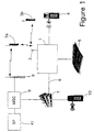
- FIG. 1 shows a customer base station apparatus 1 according to the invention having a radio antenna 2 for communication using a cordless protocol with mobile stations 3A, 3B and fixed connections to a fixed telephone instrument 4 and an answering machine 5.
- the apparatus 1 is connected by means of a fixed exchange line 6 to a conventional public switched telecommunications network (PSTN) 7.
- PSTN public switched telecommunications network
- the mobile units 3a and 3b may also communicate (as shown for mobile unit 3a) with a cellular radio system using a cellular protocol such as GSM (Global System for Mobile Telecommunications) by means of a base transceiver site 8 (BTS) and a mobile switching centre (MSC) 9 which is connected to the fixed switching system 7.
- GSM Global System for Mobile Telecommunications
- BTS base transceiver site 8
- MSC mobile switching centre
- a service point 43 is also connected to the mobile switching centre 9.
- Incoming calls can be made to the users of the equipment 1 by callers such as caller 10 connected to the switched telecommunications system 7 (or indeed the mobile system 9) in the conventional way.
- the handset 3a also has a telephone number in the cellular system, referred to hereinafter as the "remote number".
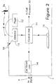
- FIG. 2 shows in more detail part of the telephone apparatus 1, specifically a control unit 11.
- the control unit 11 has input from a cordless handset detector 13 and from a manual input unit (here embodied as a keyboard 15). Although illustrated here as a separate unit, the manual input may be provided using the keypad of one of the telephones 3a, 3b, 4.
- the detector 13 in turn has input from a cordless handset cradle 16 and from the radio antenna 2.
- a pager unit 12, for transmitting paging signals to the cordless handsets through the antenna 2 is also provided.
- the control unit 11 has two outputs, firstly to a call divert unit 14 which in turn has an output to the PSTN 7 by way of exchange line 6.
- the second output from the control unit 11 is to a call processor unit 20 shown in Figure 3.
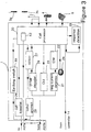
- FIG. 3 shows the call processor unit 20 and various ancillary units which also form part of the apparatus 1.
- the call processor unit also has a called number identity (CNI) unit 22 and a calling line identity (CLI) unit 23, both of which detect incoming signals from the exchange line connection 6.
- CNI called number identity
- CLI calling line identity
- the exchange line 6 feeds a ringing current detector 21, which identifies the presence of ringing current and passes a signal indicative of the ringing current to the called number identity unit 22.
- the call processor 20 is selectively connectable to the antenna 2, telephone 4 and answering machine 5 for routing incoming calls, in response to the various inputs to the call processor.
- the call processor 20 is under control of a clock 24.
- the call processor 20 is also associated with a response detection unit 25, which returns an input to the call processor 20.
- the call processor 20 also has an output to a call transfer unit 26, which in turn has an output to the exchange line 6.
- the call processor 20 also has an output to an option processor 27 which in turn has an output to a caller prompt generator 28 which itself has an output to the exchange line 6.
- a further input from the exchange line 6 leads to a DTMF decoder 29 which in turn feeds back to the option processor 27 to provide a further input to the call processor 20.
- the call processor unit 20 also controls an earthing switch 30 which causes one or other wire of the PSTN connection 6 to be connected to "earth" (zero) potential, thereby simulating the operation of the "recall” button on a conventional telephone.
- this switch may be replaced by a generator of a 'loop disconnect' signal, or any other signal recognisable as a "recall” instruction by the PSTN 7.
- the call processor 20 also includes a data message generator 42, to be described with reference to Figure 4, which has an output to the PSTN 7.
- FIG. 4 shows certain elements of the processor 20 and their interaction with the input signal detectors 22, 23.
- Incoming calls from the exchange line 6 are routed, through a processor 40 (forming part of the call processor 20), to an answering machine 5.
- a handset may also be connected, using which a user may intercept the call before the answering machine responds.
- the processor 40 on detection of acquisition of the call by the answering machine 5, controls the data collection unit 41 which obtains data from the called number identification unit 22, the calling line identifier 23 and the clock 24 for passing to the data generator 42 which generates a data message for transmission by way of the exchange line 6.
- Telephone network services are being developed which allow several users to make use of the same exchange line and for the various users of the service to have personalised services although sharing the same line.
- the call handling unit 1 is designed to make use of these services, in many cases operating them automatically instead of by means of user input, in order to provide additional services, and in particular to allow call diversion, selective call transfer and other call handling functions to be performed in response to the nature of incoming calls, with minimal additional input from the user himself.
- the system is designed to allow the user of a dual mode cordless/cellular handset to be reachable by the same telephone number whether he is within range of his cordless base station or not, but by the most economical route, without complex inputs by either the called or calling party.
- the system also allows the user to handle individual calls in a manner most appropriate to the nature of the calling and called parties automatically, without the need for any specialised input from the user once the system has been configured to the user's individual requirements.
- the call handling unit 1 described below operates in conjunction with conventional cordiess and/or fixed handsets, and a conventional answering machine 5. However, if preferred the answering machine functionality may be incorporated within the call handling unit 1. Further telephone apparatus may be connected to the exchange line 6 in parallel with the unit 1. In one possible arrangement, the call-handling unit 1 replaces the base station of a conventional domestic cordless system, connected in parallel with one or more fixed telephones. In this arrangement the fixed telephones would not be controlled by the unit 1.
- the call handling unit 1 is intended to work with existing public switched telephone networks and cellular radio networks, using network services which already exist or have been proposed for introduction in the near future.
- a telephone network operator would therefore offer the call handling unit 1 and a suitable package of its existing network services in order to provide all the necessary functionality.
- Called Number identity (CNI) has already been described. Other such network services will now be described.
- Apparatus suitable for converting these signals for display of the caller's identity can be provided, giving the called party the ability to identity a caller and to choose whether to answer the call, greet the caller by name when answering, or (if the apparatus stores the display after the caller has rung off) to return a call if the called party is unable to answer it at the time it is made.
- Systems have been developed which allow the use of "Calling Line Identity" (CLI) to determine whether a call is to be answered, and which handset to ring of several wired to a control unit. An example of such a system is disclosed in International Patent Specification no.
- a network service in which a user can divert incoming calls to another number by programming the exchange to reroute the calls, for example by transmitting DTMF (dual tone multiple frequency) tones by means of keystrokes on his telephone keypad.
- DTMF dual tone multiple frequency
- PBX private exchanges
- the transfer is effected by "parking" the incoming call using an earthing key (usually known as the "recall” button), and then dialling the new number. Normally this takes place whilst the call is in progress (i.e. after the call has been answered), but in the present embodiment the apparatus is arranged to carry out the transfer as soon as the connection to the called party is made, and before ringing tone is applied to the handset.
- Call Transfer is distinct from Call Diversion in that Call Diversion causes all incoming calls to be intercepted by the exchange and routed directly to the remote number, without the involvement of the exchange line associated with the number dialled. Call Diversion involves less signalling overhead, and will operate even if the line is already in use, but it is less versatile as it does not permit the called party to select different treatment for different calls.
- routing generally includes both call transfer and call diversion, and It also embraces the connection of a call by a base station to one or other of the apparatus associated with it (e.g. an answering machine or a cordless handset). However, individual embodiments need not be capable of supporting all such functions.
- a user input 15 (illustrated as a keyboard) allows the user to programme the call processor 20 to handle different types of call in different ways according to a number of criteria which the user may wish to apply. For example the user may wish to distinguish between incoming calls made on the "primary" number and those made on the "alternative" number (which the call processor 20 can distinguish by the different ringing cadences as will be described), or by the identity of the caller making the call (using CLI).
- the user may wish to select that the only calls to be routed to the cellular telephone number when the mobile station 3a is not within range of the cordless base station apparatus 1 are those directed to the primary number and originating from certain selected directory numbers. This would ensure that only business calls from certain selected callers would reach him: less urgent calls, and calls intended for other users or other handsets, being handled by the base station e.g. by being routed to an answering machine 5. Routing to directory numbers other than the user's own cellular telephone number is also possible.
- the user input 15 may be used to programme the controller on a real-time basis when the user takes his handset out of, or back into, range of the base station 1.
- the user input 15 may also be used to configure that certain categories of call (for instance a specific CLI) is not to be answered at all. This would be useful for example as an automatic screening of nuisance calls from a known source.
- the table below shows an exemplary pattern of call handling which may be programmed into the call processor 20 by means of the control unit 11 and user input 15.
- the "primary number” may be considered to be the user's business number and "alternative number" the user's private number, but they may be used in any other way that the user requires, for example to identifv calls to different household members.
- Category 1 CLIs may be for example business associates whom the user of the primary number wishes to be able to reach him using his cellular telephone 3a even if he is away from base.
- the call processor 20 will be programmed such that if the handset 3a is not detected by the detector 13, as will be described below, the call is transferred by way of the PSTN and the mobile network 8 and 9 to access the user handset 3a on the remote number by means of the cellular network.
- the associates may also wish to contact the location rather than the person and they may do this by dialling the "alternative number" instead of the "primary number".
- the primary number and alternative number are used in this example to contact different members of the household etc, by ringing different handsets.
- Category 3 is, for example, the Calling Line Identity of a known nuisance caller from whom none of the users wish to answer any calls.
- a user could use a Calling Line Identity display to determine whether to lift the receiver, but the telephone would nevertheless ring.
- the called party has to check the CLI display before answering the call, and an answering machine, if fitted, would answer the call if the user does not pick it up.
- the system would not route the call to any handset (or other device such as the answering machine 5), and would simply present the caller with ringing tone, without the called party even being aware of it.
- the settings set by the control unit 11 may include a hierarchy of conditions for use in turn, in the event that the preferred condition shown in Table 1 is not answered. In each case the hierarchy should eventually finish at either the answering machine or "no answer". It should also be recognised that Table 1 shows the settings at a particular time.
- the controller may be set to programme the call processor to vary the settings according to a predetermined schedule which may be a diary system or a regular "time of day" schedule. For example all calls may be routed to the answering machine during the night.
- the control unit 11 has a second input from a handset detector 13. This allows the controller to set the call processor 20 to answer calls or divert them to the cellular number according to whether the dual mode handset 3a is within range of the cordless base station antenna 2.
- a paging system is used to determine whether the handsets 3a, 3b are within wireless communication range of the cordless base station antenna 2.
- This is an adaptation of the known cordless paging systems which operate when a call attempt is being made to or from the handset.
- the pager 12 causes an interrogation signal to be sent periodically, whether or not a call attempt is being made, which the handset will respond to in the normal way if it is in within range.
- the detector 13 determines whether the signal from the pager 12 has been responded to, and if the handset is newly absent, or newly present it initiates or cancels call diversions accordingly.
- the call routing function may be arranged to be initiated by the control unit 11 only if a predetermined number of consecutive pagings, for example three, achieve the same response.
- the paging rate may be increased if a change is detected, to allow such consecutive pagings to take place over a shorter timescale than would otherwise be the case, this identifying a change more quickly.
- the paging rate may also be varied according to the detected signal level, so that if a handset is close to the limits of the range, and this likely to make a transition, that transition is identified more readily.
- the detector 13 may have a second mode of operation, in which it can detect the presence of the handset 3a in a cradle 16. If the base station has more than one associated handset the detector 13 can be arranged to identify which handsets are present.
- the cradle 16 may be arranged to identify each individual handset.
- the cradle 16 may also serve as a battery charger for the handset 3a, and one possible way in which the recognition of the handset may be achieved is by providing a different configuration of electrical connections on each handset 3a, 3b, compatible with different terminals on the cradle 16, such that the cradle can detect which of its terminals are connected to the handset 3a or 3b, and therefore which handset is in the cradle 16.
- Each handset may have its own dedicated cradle, so that occupancy of a given cradle indicates the presence of its respective handset.
- each cradle may be able to accommodate any handset, and have means as described above for identifying the handset currently occupying it.
- the handset continues to be paged by the wireless system whilst it is in the cradle.
- the cradle may be arranged to detect whether it is occupied, the handset being paged when it is first put into the cradle and, once it responds, its presence in the cradle being then inferred as long as the cradle remains occupied. Paging would be resumed when the cradle is vacated.
- the controller 11 compiles its instructions to the call processor according to both the manual input from the input device 15 and the output of the detector 13. If all calls intended for the "primary number" are to be diverted to the cellular number when the cordless handset is not detected, the controller 11 sets up a call divert using a call divert unit 14 to transmit the necessary DTMF signals to instruct the exchange in the PSTN 7 that calls to the "primary number" of the relevant handset are to be diverted to the "remote number", which is the cellular directory number associated with the handset 3a. Calls intended for the "alternative number" remain undiverted.
- This arrangement allows automatic diversion to the remote number of all calls made to the "primary number" of the handset 3a whenever the handset 3a is out of range of the base station 2, and the cancellation of such diversions when the handset comes within range of the base station 2, without any need for manual input by the user. Indeed the user need not be aware whether he is within or outside range of the base station 2.
- the user input 15 may be used to programme that calls are only to be diverted by the controller 11 at certain times, by programming the controller 11 to override the indication from the detector at other times.
- the controller does not direct the call divert unit 14 to set up a call divert for all incoming calls. Instead, incoming calls are handled individually by the call processor 20, which can transfer incoming calls to other exchange lines if required. In this case it is only necessary to page the handsets when an incoming call attempt is made.
- a specified primary number e.g. having a predetermined CNI
- the call processor unit 20 is configured by the control unit 11 to handle different types of incoming calls in different ways according to a number of inputs made at the time that the incoming call is made. These inputs are:
- the called number is identified by means of a ringing current detector 21, which detects the pulses of ringing current, and the pattern of this ringing current is transferred to the called number identifier 22 to determine which ringing cadence is being sent from the PSTN exchange 7, and therefore which of the directory numbers associated with the exchange line 6 has been dialled.
- the called number identifier merely needs to identify whether the cadence is that dedicated to one of the numbers (e.g. the "primary number"); any other cadence must, by default, be that for the other number.
- the original purpose of providing different ringing sequences is to allow users to recognise which number has been dialled, and therefore to answer the call appropriately, and therefore in practice ringing sequences are selected which can be readily distinguished by human beings.
- the ringing current detector 21 and called number identifier 22 can distinguish them, more subtle differences in ringing cadence may be used in the system of the invention.
- the call processor 20 acts upon the various inputs, according to its programming, to transfer the call by means of the call transfer unit 26, if appropriate. If the call is not to be transferred, ringing current (with the appropriate cadence) may be applied to the equipment 3a, 3b, 4 and 5. The processor may be arranged to route the call only to the certain of these equipments. if no response is received from the selected equipment 3a, 3b, 4, 5, this fact is detected by a response detector 25. The response detector 25 counts the number of pulses of ringing current received, and if a predetermined number of pulses is reached instructs the call processor 20 to move to the next condition in the hierarchy.
- the call transfer unit 26 transmits a message via the line 6 to the PSTN 7 instructing it to transfer the call to the remote number, for example the cellular number associated with the handset 3a.
- the call processor 20 On receiving an incoming call the call processor 20 first earths the connection 6 from the PSTN 7, using the earthing switch 30, which performs the same function as the 'R' or "recall” button on a conventional telephone in order to 'park' the call in the PSTN 7. In the event that the call is not to be answered at all, the connection simply remains "parked", until the caller hangs up.
- This feature allows the caller 10, as well as the called party, to have a say in how the call is answered. From some or all categories of call, when the call processor unit 20 detects an incoming call having a specified CLI and CNI, and in accordance with the time of day, it answers the call (i.e. it goes "off-hook"), and instructs an option generator 27 to transmit a prompt to the caller 10.
- This prompt is a voice-generated "menu" offering the caller 10 certain options.
- the options can be selected according to the individual call's CLI and CNI, the time of day and the presence or absence of the handsets 3a, 3b.
- the options generated by the option generator 27 are processed into a voice message by a caller prompt unit 28 for transmission over the PSTN 7 to the caller.
- the voice message invites the caller 10 to transmit a selection using voice commands or DTMF tones.
- the selection is received back from the caller 10 by way of the PSTN exchange 7 and exchange line 6 and is decoded by a DTMF decoder 29 to identify which of the offered options has been selected.
- the option selected is input into the call processor unit 20 from where the selected handset 3a, 3b, fixed telephone 4, or answering machine 5 is activated.
- the response detector 25 causes the call processor unit 20 to either default to another condition as already described, or to return to the option generator 27 to offer a revised list of options, omitting the option which failed.
- the call divert unit 14 and its output to the network 7 could be dispensed with, all incoming calls being handled by the call processor 20 instead, being transferred to the remote number if the CNI is appropriate.
- the call transfer unit 26 instead of using the call transfer unit 26, such diverted calls can be connected more quickly, and without the need for the involvement of the user's call handling unit 1 or the exchange connection 6 for each call. In particular, it allows such calls to be diverted even if the exchange connection 6 is in use.
- the clock 24 can be dispensed with. In this case, all call handling would be processed according to manual inputs and the detection (or otherwise) of handsets.
- the apparatus illustrated in Figure 4 generates a data message to send to a separate exchange line when a message is left on the answering machine 5.
- the call is routed to the answering machine 5, and possibly other terminals. If the call is answered by the answering machine 5 (e.g. because it is not intercepted by another terminal first) this is detected by the processor 40 which causes the data collection unit 41 to operate.
- the data collection unit 41 detects the called and calling numbers using the inputs from the identifiers 22 and 23 and the time and duration of call as determined from the clock 24 and triggered by the start and finish of the connection to the answering machine 5.
- the data collected is transmitted to a data generator 42 which generates a data message according to a suitable protocol.
- SMS Short Message Service
- GSM Global System for Mobile Communications
- the SMS Service Point 43 allows for re-formatting. If the data medium is compatible with the PSTN (and in particular the exchange line 6), the message can be routed directly to the mobile handset 3a. However, the use of a Service Point 43 also allows data messages to be stored if a handset is temporarily unavailable, for example because it is out of range, or switched off.
Description
characterised in that the apparatus comprises signal recognition means suitable for detecting and recognising a ringing pattern or cadence of signalling, associated with an incoming call, transmitted over the exchange line to the apparatus, and for controlling the call handling means in accordance with the ringing pattern or cadence.
characterised in that the apparatus detects which of a predetermined set of ringing patterns or cadences is transmitted from the network and selects a call handling mode accordingly.

Claims (20)
- A telephone apparatus having exchange connection means (6) suitable for connection, by means of a telecommunications exchange line, to a telecommunications network (7); and call handling means (20) for handling the incoming call according to the origin of the call,
characterised in that the apparatus comprises signal recognition means (21, 22) suitable for detecting and recognising a ringing pattern or cadence of signalling, associated with an incoming call, transmitted over the exchange line to the apparatus, and for controlling the call handling means (20) in accordance with the ringing pattern or cadence. - Telephone apparatus according to claim 1, wherein the call handling means (20) includes means (26) for transferring the incoming call to a second exchange line in response to the recognition of a predetermined ringing pattern or cadence.
- Telephone apparatus according to claim 2, wherein the means for transferring an incoming call comprises means (30) for transmitting a signal to the telecommunications network in order to disconnect the incoming call from the exchange line, and means for transmitting a signal over the exchange line to the telecommunications network, the signal being indicative of the second exchange line to which the incoming call is to be transferred.
- Telephone apparatus according to claim 1, wherein the handling means (20) includes means for causing a signal to be transmitted over the telephone network to a predetermined telephone connection in response to an incoming call.
- Telephone apparatus according to claim 4 for connection to a telephone network (7) and to a telephone answering machine (5), comprising means for causing an incoming telephone call to be handled by the telephone answering machine (5), and signal generation means (42) for causing a signal to be transmitted over the telephone network (7) to a predetermined receiving telephone connection in response to a call being routed to the answering machine (5).
- Telephone apparatus according to claim 5, wherein the predetermined receiving telephone connection is a GSM-standard mobile telephone, and the signal generation means (42) has means for generating a signal according to the GSM short message service (SMS) protocol for transmission to a GSM standard mobile telephone.
- Telephone apparatus according to claim 5 or 6, wherein the signal generation means (42) generates a signal indicative of any one or more of the calling party, the called number, the duration of the message, and the time at which the incoming call was made.
- Telephone apparatus according to any preceding claim having at least one cordless handset connection means (2) suitable for establishing wireless communication between the apparatus and a respective handset or handsets (3a, 3b), having detection means (13) for detecting the presence or absence of such handsets, and programming means (11) to change the correspondence between ringing patterns or cadences and handling process according to the presence or absence of the handsets.
- Telephone apparatus according to any preceding claim, including programming means for programming the call handling means such that the correspondence between signal characteristics and call handling selection can be varied, wherein the programming means includes caller control means , the caller control means comprising option selection means (27) to select two or more handling options, selected according to the characteristics of the signalling received, message generation means (42) for transmitting an option message over the exchange connection to the maker of an incoming call offering the options selected by the option selection means (27), detection means (29) for detecting signals received from the exchange connection in response to the option message, and means (20) for controlling the call handling selection means in response to the signals detected by the detection means (29).
- A method of operating a telephone apparatus (1) connected to a telephone network (7) by means of an exchange line (6), wherein on an incoming call attempt being made from the network, the call is handled according to a selected one of a plurality of modes under the control of the apparatus,
characterised in that the apparatus detects which of a predetermined set of ringing patterns or cadences is transmitted from the network (7) and selects a call handling mode accordingly. - Method according to claim 10 wherein the ringing pattern or cadence is generated by the network (7) and is indicative of which of a plurality of telephone numbers associated with the exchange line (6) was used to make the call.
- Method according to claim 10 wherein one or more of the handling modes is a transfer of the incoming call to a second exchange line.
- Method according to claim 12, wherein one of the call handling modes transfers calls to another exchange line by transmitting a signal to the telecommunications network in order to disconnect the incoming call from the exchange line (6), and transmitting a signal over the exchange line to the telecommunications network (7), the signal being indicative of the second exchange line to which the call is to be transferred.
- Method according to claim 10 or 11 wherein a signal is transmitted over the telephone network to a predetermined telephone connection in response to an incoming call.
- Method according to claim 14 wherein calls may be handled by activation of a telephone answering machine (5), and a signal is generated for transmission over the telephone network (7) to a predetermined telephone connection in response to a call being so handled by the answering machine (5).
- Method according to claim 15, wherein the signal is generated according to the GSM short message service (SMS) protocol for transmission to a GSM standard mobile telephone.
- Method according to claim 15 or 16 wherein the signal generated is indicative of any one or more of the calling party, the called number, the duration of the message, and the time at which the incoming call was made.
- Method according to any of claims 10 to 17, wherein the apparatus is associated with one or more removable handsets (3a, 3b), and the correspondence between signal characteristics and handling process selection is varied according to the presence or absence of the removable handsets (3a, 3b).
- Method according to claim 18, wherein the removable handsets (3a, 3b) communicate with the apparatus (1) by wireless means (2) when in the presence of the apparatus (1).
- Method according to any of claim 10 to 19, further comprising the steps of:a) transmitting a message offering handling options to the calling party, the options offered being selected according to the characteristics of the signalling associated with the call attempt;b) receiving handling instructions from the calling party; andc) handling the incoming call according to said handling instructions.
Priority Applications (1)
| Application Number | Priority Date | Filing Date | Title |
|---|---|---|---|
| EP97930661A EP0910916B1 (en) | 1996-07-11 | 1997-07-07 | Telephone apparatus |
Applications Claiming Priority (6)
| Application Number | Priority Date | Filing Date | Title |
|---|---|---|---|
| EP96305370 | 1996-07-11 | ||
| EP96305600 | 1996-07-11 | ||
| EP96305600 | 1996-07-11 | ||
| EP96305370 | 1996-07-11 | ||
| PCT/GB1997/001850 WO1998003004A1 (en) | 1996-07-11 | 1997-07-07 | Telephone apparatus |
| EP97930661A EP0910916B1 (en) | 1996-07-11 | 1997-07-07 | Telephone apparatus |
Publications (2)
| Publication Number | Publication Date |
|---|---|
| EP0910916A1 EP0910916A1 (en) | 1999-04-28 |
| EP0910916B1 true EP0910916B1 (en) | 2003-10-15 |
Family
ID=26143806
Family Applications (1)
| Application Number | Title | Priority Date | Filing Date |
|---|---|---|---|
| EP97930661A Expired - Lifetime EP0910916B1 (en) | 1996-07-11 | 1997-07-07 | Telephone apparatus |
Country Status (6)
| Country | Link |
|---|---|
| US (1) | US6192231B1 (en) |
| EP (1) | EP0910916B1 (en) |
| JP (1) | JP2000514627A (en) |
| AU (1) | AU3453797A (en) |
| DE (1) | DE69725578T2 (en) |
| WO (1) | WO1998003004A1 (en) |
Families Citing this family (49)
| Publication number | Priority date | Publication date | Assignee | Title |
|---|---|---|---|---|
| US20080207197A1 (en) * | 1997-07-30 | 2008-08-28 | Steven Tischer | Apparatus, method, and computer-readable medium for interfacing devices with communications networks |
| US20080207202A1 (en) * | 1997-07-30 | 2008-08-28 | Zellner Samuel N | Apparatus and method for providing a user interface for facilitating communications between devices |
| US20080192769A1 (en) * | 1997-07-30 | 2008-08-14 | Steven Tischer | Apparatus and method for prioritizing communications between devices |
| US20080194251A1 (en) * | 1997-07-30 | 2008-08-14 | Steven Tischer | Apparatus and method for providing communications and connection-oriented services to devices |
| US20080220776A1 (en) * | 1997-07-30 | 2008-09-11 | Steven Tischer | Interface devices for facilitating communications between devices and communications networks |
| US20080195641A1 (en) * | 1997-07-30 | 2008-08-14 | Steven Tischer | Apparatus and method for aggregating and accessing data according to user information |
| US7149514B1 (en) | 1997-07-30 | 2006-12-12 | Bellsouth Intellectual Property Corp. | Cellular docking station |
| DE19824141A1 (en) * | 1998-05-29 | 1999-12-02 | Siemens Ag | Handover procedure (roaming) for mobile terminal equipment |
| US6289099B1 (en) * | 1998-11-30 | 2001-09-11 | Qualcomm Inc. | Ringer for satellite user terminals |
| US6681119B1 (en) * | 1998-12-31 | 2004-01-20 | Nortel Networks Ltd | Wireless communication system in which a call from a private branch exchange is selectively delivered to a mobile unit |
| US6411802B1 (en) * | 1999-03-15 | 2002-06-25 | Bellsouth Intellectual Property Management Corporation | Wireless backup telephone device |
| DE19915548C2 (en) * | 1999-04-07 | 2001-02-15 | Plus Mobilfunk Gmbh E | Method for combining landline and mobile telephony |
| US6427074B1 (en) * | 1999-08-31 | 2002-07-30 | Avaya Technology Corp. | Battery charging indication message from a wireless terminal |
| GB2358771B (en) * | 2000-01-27 | 2003-08-06 | Phillip Jarrett | Multi-purpose mobile cordless phone system |
| US6725045B2 (en) * | 2000-07-05 | 2004-04-20 | Virtual Extension Ltd. | System and method for locating personal units, notifying called parties of incoming calls and automatically routing calls to desired telephone stations |
| US20020168998A1 (en) * | 2001-05-10 | 2002-11-14 | Van Winkel Robert J. | Cellular telephone interface device and method |
| FR2825560B1 (en) * | 2001-05-31 | 2003-09-26 | Sagem | TELEPHONY METHOD AND BASIS WITH DYNAMIC ADVERTISING MESSAGE COMPOSITION |
| FR2825554B1 (en) * | 2001-05-31 | 2005-06-17 | Sagem | METHOD FOR FILTERING TELEPHONE CALLS, TELEPHONE BASE AND TERMINAL FOR IMPLEMENTING THE METHOD |
| FR2826538B1 (en) * | 2001-06-25 | 2005-06-17 | Sagem | METHOD OF DIRECT SELECTION AT THE ARRIVAL OF TELEPHONE CALLS ARRIVING ON A BASE AND BASIS FOR THE IMPLEMENTATION OF THE METHOD |
| US7792484B2 (en) * | 2001-07-05 | 2010-09-07 | Telefonaktiebolaget Lm Ericsson (Publ) | Arrangement and a method in a telephony system permitting communication using a stationary telephony terminal via a mobile radio telephone |
| US7120454B1 (en) | 2001-12-26 | 2006-10-10 | Bellsouth Intellectual Property Corp. | Auto sensing home base station for mobile telephone with remote answering capabilites |
| US7684383B1 (en) * | 2002-01-30 | 2010-03-23 | 3Com Corporation | Method and system for dynamic call type detection for circuit and packet switched networks |
| US8000682B2 (en) * | 2002-07-15 | 2011-08-16 | At&T Intellectual Property I, L.P. | Apparatus and method for restricting access to data |
| US8416804B2 (en) * | 2002-07-15 | 2013-04-09 | At&T Intellectual Property I, L.P. | Apparatus and method for providing a user interface for facilitating communications between devices |
| US7200424B2 (en) * | 2002-07-15 | 2007-04-03 | Bellsouth Intelectual Property Corporation | Systems and methods for restricting the use and movement of telephony devices |
| US8275371B2 (en) | 2002-07-15 | 2012-09-25 | At&T Intellectual Property I, L.P. | Apparatus and method for providing communications and connection-oriented services to devices |
| US8526466B2 (en) | 2002-07-15 | 2013-09-03 | At&T Intellectual Property I, L.P. | Apparatus and method for prioritizing communications between devices |
| US8554187B2 (en) * | 2002-07-15 | 2013-10-08 | At&T Intellectual Property I, L.P. | Apparatus and method for routing communications between networks and devices |
| US8543098B2 (en) * | 2002-07-15 | 2013-09-24 | At&T Intellectual Property I, L.P. | Apparatus and method for securely providing communications between devices and networks |
| DE10329960A1 (en) * | 2003-07-03 | 2005-03-17 | Deutsche Telekom Ag | Switching control system is used to provide a connection between a fixed communication network and a mobile telephone network |
| US20050201534A1 (en) * | 2004-03-10 | 2005-09-15 | Ignatin Gary R. | Method for call screening in a voice mail system |
| US20050202810A1 (en) * | 2004-03-11 | 2005-09-15 | Lapallo George | Mobile and landline connection |
| US8966498B2 (en) | 2008-01-24 | 2015-02-24 | Oracle International Corporation | Integrating operational and business support systems with a service delivery platform |
| US9565297B2 (en) | 2004-05-28 | 2017-02-07 | Oracle International Corporation | True convergence with end to end identity management |
| US9038082B2 (en) | 2004-05-28 | 2015-05-19 | Oracle International Corporation | Resource abstraction via enabler and metadata |
| US9245236B2 (en) * | 2006-02-16 | 2016-01-26 | Oracle International Corporation | Factorization of concerns to build a SDP (service delivery platform) |
| US20060116912A1 (en) * | 2004-12-01 | 2006-06-01 | Oracle International Corporation | Managing account-holder information using policies |
| US7983680B2 (en) * | 2005-08-10 | 2011-07-19 | Nextel Communications Inc. | System and method for converged network services |
| US8914493B2 (en) * | 2008-03-10 | 2014-12-16 | Oracle International Corporation | Presence-based event driven architecture |
| US8224307B2 (en) * | 2006-10-06 | 2012-07-17 | Embarq Holdings Company, Llc | System and method for transferring telephone calls between mobile and cordless modes |
| US8214503B2 (en) * | 2007-03-23 | 2012-07-03 | Oracle International Corporation | Factoring out dialog control and call control |
| US9654515B2 (en) * | 2008-01-23 | 2017-05-16 | Oracle International Corporation | Service oriented architecture-based SCIM platform |
| US10819530B2 (en) | 2008-08-21 | 2020-10-27 | Oracle International Corporation | Charging enabler |
| US8879547B2 (en) | 2009-06-02 | 2014-11-04 | Oracle International Corporation | Telephony application services |
| US20110125913A1 (en) * | 2009-11-20 | 2011-05-26 | Oracle International Corporation | Interface for Communication Session Continuation |
| US9269060B2 (en) * | 2009-11-20 | 2016-02-23 | Oracle International Corporation | Methods and systems for generating metadata describing dependencies for composable elements |
| US20110125909A1 (en) * | 2009-11-20 | 2011-05-26 | Oracle International Corporation | In-Session Continuation of a Streaming Media Session |
| US9509790B2 (en) | 2009-12-16 | 2016-11-29 | Oracle International Corporation | Global presence |
| US9503407B2 (en) * | 2009-12-16 | 2016-11-22 | Oracle International Corporation | Message forwarding |
Family Cites Families (62)
| Publication number | Priority date | Publication date | Assignee | Title |
|---|---|---|---|---|
| FR2538978B1 (en) | 1982-12-29 | 1985-05-31 | Grandmougin Michel | TELEPHONE SET WITH BIDIRECTIONAL INFRARED LINK BETWEEN HANDSET AND FIXED MODULE CONNECTED TO A TELEPHONE LINE |
| US4528424A (en) | 1983-06-24 | 1985-07-09 | International Telephone And Telegraph Corporation | Multiparty line adapter with privacy feature controlled by reversal of line polarity at a central power source |
| US4741019A (en) | 1984-03-15 | 1988-04-26 | Sanyo Electric Co., Ltd. | Cordless telephone |
| US5375161A (en) | 1984-09-14 | 1994-12-20 | Accessline Technologies, Inc. | Telephone control system with branch routing |
| US4802200A (en) | 1985-08-27 | 1989-01-31 | Nippon Telegraph And Telephone Corporation | Radio telephone system control apparatus and method |
| FR2593656B1 (en) | 1986-01-28 | 1994-04-29 | Parienti Raoul | COMPACT WIRELESS INDIVIDUAL COMMUNICATION METHOD OPERATING ON AN INFRARED DUPLEX NETWORK AND ITS IMPLEMENTING DEVICE. |
| DE3880038T2 (en) | 1987-07-31 | 1993-07-15 | Nec Corp | ENTERING A NEW CORDLESS TELEPHONE IN AN EXISTING SYSTEM. |
| GB2209109A (en) | 1987-08-26 | 1989-04-26 | Philips Nv | Pabx cordless telephone system |
| US5210785A (en) | 1988-02-29 | 1993-05-11 | Canon Kabushiki Kaisha | Wireless communication system |
| US4942598A (en) | 1988-03-04 | 1990-07-17 | Motorola, Inc. | Telephone answering machine in paging systems with automatic number identification based message operations |
| AT390702B (en) | 1988-05-20 | 1990-06-25 | Siemens Ag Oesterreich | CORDLESS TELEPHONE DEVICE |
| FR2634081B1 (en) | 1988-07-08 | 1994-07-01 | Parienti Raoul | PRIVATE COMMUNICATION SYSTEM |
| US5109405A (en) | 1988-07-11 | 1992-04-28 | Dytel Corporation | Automated call screening |
| JPH0243854A (en) | 1988-08-04 | 1990-02-14 | Toshiba Corp | Radio telephone set |
| EP0433308B1 (en) | 1988-09-12 | 1996-07-10 | Motorola, Inc. | Two-way radio communications system having selectable operating modes |
| US5168517A (en) * | 1989-03-13 | 1992-12-01 | Herbert Waldman | Apparatus and methods for selectively forwarding telephone calls |
| WO1991000664A1 (en) | 1989-06-30 | 1991-01-10 | Nippon Telegraph And Telephone Corporation | Personal communication system |
| US5062133A (en) * | 1989-07-07 | 1991-10-29 | Logotronix Incorporated | Multi-function telephone call management system |
| IE903907A1 (en) * | 1989-10-31 | 1991-05-08 | Anderson John James | Exchange area network and related devices |
| US4980907A (en) | 1989-12-15 | 1990-12-25 | Telefonaktiebolaget L M Ericsson | Telecommunication combination comprising a telepoint and a portable radio terminal |
| US5222123A (en) * | 1990-01-08 | 1993-06-22 | Motorola, Inc. | Registration and automatic call redirecting for cordless telephone systems |
| GB2241851A (en) | 1990-03-09 | 1991-09-11 | Philips Electronic Associated | Optimising transmitter power in a communications system |
| US5142569A (en) * | 1990-04-23 | 1992-08-25 | Data Accessory Corporation | Apparatus for selectively enabling subscriber device to respond to ringing signal in dependence upon ringing cadence |
| US5313516A (en) | 1990-05-31 | 1994-05-17 | Phonemate Inc. | Telephone answering device with automatic function |
| WO1992004798A1 (en) | 1990-09-04 | 1992-03-19 | Motorola, Inc. | Method and apparatus for selective transfer of calls in personal communicators |
| EP0836350A3 (en) * | 1990-11-29 | 1999-06-02 | Fujitsu Limited | ISDN interface unit |
| JPH05176050A (en) * | 1991-02-18 | 1993-07-13 | Matsushita Electric Ind Co Ltd | Automatic answering telephone system |
| JPH05160886A (en) * | 1991-12-09 | 1993-06-25 | Canon Inc | Digital terminal equipment |
| US5577104A (en) * | 1992-02-05 | 1996-11-19 | Casio Phonemate, Inc. | Method for system and message activation based on distinctive ringing |
| CA2105966C (en) | 1992-02-06 | 1997-09-30 | James M. Williams | Call routing for a radiotelephone in multiple radiotelephone systems |
| US5353331A (en) * | 1992-03-05 | 1994-10-04 | Bell Atlantic Network Services, Inc. | Personal communications service using wireline/wireless integration |
| FR2691599B1 (en) | 1992-05-22 | 2001-08-10 | France Telecom | Device for controlling access to a telephone line. |
| US5559860A (en) | 1992-06-11 | 1996-09-24 | Sony Corporation | User selectable response to an incoming call at a mobile station |
| GB9214186D0 (en) | 1992-07-03 | 1992-08-12 | Plessey Telecomm | Mobile cordless telephone systems |
| US5363426A (en) | 1992-07-06 | 1994-11-08 | Motorola, Inc. | Extended range paging for a radio frequency communication system |
| NL9201577A (en) * | 1992-09-10 | 1994-04-05 | Ericsson Business Mobile Netwo | Telephone system with different ring patterns. |
| JP2997138B2 (en) | 1992-10-19 | 2000-01-11 | 富士通株式会社 | Cordless system |
| EP0608654A1 (en) | 1992-12-30 | 1994-08-03 | International Business Machines Corporation | Telephone directing method and apparatus |
| CA2110352C (en) | 1993-02-26 | 1998-02-24 | Bruce Merrill Bales | Calling terminal controlled call coverage |
| WO1994022240A1 (en) | 1993-03-19 | 1994-09-29 | Motorola, Inc. | Method and apparatus for selecting the best fixed communication unit |
| AU6416394A (en) | 1993-03-26 | 1994-10-24 | Sni Innovation, Inc. | Automatic routing of incoming telephone calls to a plurality of receiving devices based on caller identification |
| CA2123041A1 (en) | 1993-06-01 | 1994-12-02 | Charles John Malek | Method for locating a user of telephone subscriber equipment |
| DE69434524D1 (en) * | 1993-09-01 | 2005-12-01 | Canon Kk | To a switching network with distinguishable Rufkennmstern connectable message device |
| DE4330704A1 (en) | 1993-09-10 | 1995-03-16 | Sel Alcatel Ag | Telepoint system |
| US5771453A (en) | 1993-11-04 | 1998-06-23 | Ericsson Inc. | Multiple user base stations and methods for radio personal communications systems |
| JPH07212839A (en) | 1994-01-18 | 1995-08-11 | Hashimoto Corp | Automatic answering telephone equipment with paging function |
| JPH07240960A (en) | 1994-03-01 | 1995-09-12 | Toshiba Corp | Telephone system |
| US5473671A (en) | 1994-03-11 | 1995-12-05 | At&T Corp. | Selective screening of incoming calls for cellular telephone systems |
| US5502761A (en) * | 1994-03-24 | 1996-03-26 | Rolm Company | Apparatus and method for relaying calling information to a pager or alternate telephone |
| CA2126170A1 (en) * | 1994-06-17 | 1995-12-18 | Deborah L. Pinard | Automatic call router |
| EP0699009A1 (en) * | 1994-08-17 | 1996-02-28 | Alcatel SEL Aktiengesellschaft | Call mode sub-system for a mobile communications system with message service |
| US5563935A (en) * | 1994-08-17 | 1996-10-08 | Small; J. Gordon | Telephone answering system with call screening circuit |
| US5600704A (en) | 1994-08-30 | 1997-02-04 | Ericsson Inc. | Systems and methods for prioritized routing of telephone calls to a subscriber |
| US5673308A (en) | 1994-10-12 | 1997-09-30 | Bell Atlantic Network Services, Inc. | Personal phone number system |
| DE4440500A1 (en) | 1994-11-12 | 1996-05-15 | Philips Patentverwaltung | Communication system |
| US5689549A (en) | 1994-12-01 | 1997-11-18 | Lucent Technologies Inc. | Cordless telephone base unit arranged for operating with multiple portable units |
| US5668852A (en) * | 1995-01-18 | 1997-09-16 | Holmes; Terry M. | Automatic caller-associated information provision system, improvement and method for paging system |
| GB2297455B (en) | 1995-01-28 | 1999-07-14 | Motorola Ltd | Automatic call divert for cordless telephone system |
| EP0740482A1 (en) | 1995-04-28 | 1996-10-30 | Hewlett-Packard Company | Telephone management system for answering a transfering calls in a system including a mobile cellular phone |
| US5751800A (en) | 1995-12-15 | 1998-05-12 | Lucent Technologies Inc. | Screening of incoming telephone calls prior to call completion to the destination party |
| US5805680A (en) | 1996-01-02 | 1998-09-08 | At&T Corp. | Method and apparatus for telephone call sub-billing |
| US5768356A (en) * | 1996-02-20 | 1998-06-16 | Solopoint, Inc. | User programmable personal call manager |
-
1997
- 1997-07-07 US US09/068,225 patent/US6192231B1/en not_active Expired - Fee Related
- 1997-07-07 JP JP10505717A patent/JP2000514627A/en active Pending
- 1997-07-07 WO PCT/GB1997/001850 patent/WO1998003004A1/en active IP Right Grant
- 1997-07-07 EP EP97930661A patent/EP0910916B1/en not_active Expired - Lifetime
- 1997-07-07 DE DE69725578T patent/DE69725578T2/en not_active Expired - Lifetime
- 1997-07-07 AU AU34537/97A patent/AU3453797A/en not_active Abandoned
Also Published As
| Publication number | Publication date |
|---|---|
| AU3453797A (en) | 1998-02-09 |
| WO1998003004A1 (en) | 1998-01-22 |
| EP0910916A1 (en) | 1999-04-28 |
| DE69725578D1 (en) | 2003-11-20 |
| DE69725578T2 (en) | 2004-07-29 |
| JP2000514627A (en) | 2000-10-31 |
| US6192231B1 (en) | 2001-02-20 |
Similar Documents
| Publication | Publication Date | Title |
|---|---|---|
| EP0910916B1 (en) | Telephone apparatus | |
| EP0910914B1 (en) | Cordless telephone apparatus | |
| EP1023800B1 (en) | Method of sharing and transferring information between isdn telephones | |
| CA2194663C (en) | Cellular telephone and associated method for opening a voice channel with a source telephone without establishing voice communications therewith | |
| EP0896780B1 (en) | Method, device and telecommunication system for providing a consistent set of services to a roaming user | |
| CA2163745A1 (en) | Multinetwork terminal | |
| AU3769899A (en) | System and method for delivering a call for a mobile station using either a wireless network or a wireline network | |
| JPS6410150B2 (en) | ||
| EP0688126A2 (en) | A voice messaging system | |
| AU4864485A (en) | Call diverter function in an early care telephone system | |
| GB2313265A (en) | Base station for mobile telephone system which disables ringing to mobile telephones | |
| KR0134721B1 (en) | Paging method in exchange system | |
| JP2563332B2 (en) | Wireless telephone equipment | |
| JP2531347B2 (en) | Mobile communication system using portable mobile terminal | |
| JPH0456586A (en) | Radio call device | |
| JPH1188956A (en) | Automatic transfer device for personal handy phone system | |
| JPH02137456A (en) | Call waiting system | |
| JPH03175869A (en) | Speech path setting system |
Legal Events
| Date | Code | Title | Description |
|---|---|---|---|
| PUAI | Public reference made under article 153(3) epc to a published international application that has entered the european phase |
Free format text: ORIGINAL CODE: 0009012 |
|
| 17P | Request for examination filed |
Effective date: 19981201 |
|
| AK | Designated contracting states |
Kind code of ref document: A1 Designated state(s): DE FR GB IT SE |
|
| GRAH | Despatch of communication of intention to grant a patent |
Free format text: ORIGINAL CODE: EPIDOS IGRA |
|
| GRAS | Grant fee paid |
Free format text: ORIGINAL CODE: EPIDOSNIGR3 |
|
| GRAA | (expected) grant |
Free format text: ORIGINAL CODE: 0009210 |
|
| STAA | Information on the status of an ep patent application or granted ep patent |
Free format text: STATUS: THE PATENT HAS BEEN GRANTED |
|
| AK | Designated contracting states |
Kind code of ref document: B1 Designated state(s): DE FR GB IT SE |
|
| PG25 | Lapsed in a contracting state [announced via postgrant information from national office to epo] |
Ref country code: IT Free format text: LAPSE BECAUSE OF FAILURE TO SUBMIT A TRANSLATION OF THE DESCRIPTION OR TO PAY THE FEE WITHIN THE PRE;WARNING: LAPSES OF ITALIAN PATENTS WITH EFFECTIVE DATE BEFORE 2007 MAY HAVE OCCURRED AT ANY TIME BEFORE 2007. THE CORRECT EFFECTIVE DATE MAY BE DIFFERENT FROM THE ONE RECORDED.SCRIBED TIME-LIMIT Effective date: 20031015 |
|
| REG | Reference to a national code |
Ref country code: GB Ref legal event code: FG4D |
|
| REF | Corresponds to: |
Ref document number: 69725578 Country of ref document: DE Date of ref document: 20031120 Kind code of ref document: P |
|
| PG25 | Lapsed in a contracting state [announced via postgrant information from national office to epo] |
Ref country code: SE Free format text: LAPSE BECAUSE OF FAILURE TO SUBMIT A TRANSLATION OF THE DESCRIPTION OR TO PAY THE FEE WITHIN THE PRESCRIBED TIME-LIMIT Effective date: 20040115 |
|
| ET | Fr: translation filed | ||
| PLBE | No opposition filed within time limit |
Free format text: ORIGINAL CODE: 0009261 |
|
| 26N | No opposition filed |
Effective date: 20040716 |
|
| REG | Reference to a national code |
Ref country code: FR Ref legal event code: PLFP Year of fee payment: 20 |
|
| PGFP | Annual fee paid to national office [announced via postgrant information from national office to epo] |
Ref country code: DE Payment date: 20160722 Year of fee payment: 20 Ref country code: GB Payment date: 20160721 Year of fee payment: 20 |
|
| PGFP | Annual fee paid to national office [announced via postgrant information from national office to epo] |
Ref country code: FR Payment date: 20160721 Year of fee payment: 20 |
|
| REG | Reference to a national code |
Ref country code: DE Ref legal event code: R071 Ref document number: 69725578 Country of ref document: DE |
|
| REG | Reference to a national code |
Ref country code: GB Ref legal event code: PE20 Expiry date: 20170706 |
|
| PG25 | Lapsed in a contracting state [announced via postgrant information from national office to epo] |
Ref country code: GB Free format text: LAPSE BECAUSE OF EXPIRATION OF PROTECTION Effective date: 20170706 |