EP0909701B1 - Underwater device with a sacrificial latch mechanism - Google Patents
Underwater device with a sacrificial latch mechanism Download PDFInfo
- Publication number
- EP0909701B1 EP0909701B1 EP98308154A EP98308154A EP0909701B1 EP 0909701 B1 EP0909701 B1 EP 0909701B1 EP 98308154 A EP98308154 A EP 98308154A EP 98308154 A EP98308154 A EP 98308154A EP 0909701 B1 EP0909701 B1 EP 0909701B1
- Authority
- EP
- European Patent Office
- Prior art keywords
- latch body
- housing
- cable
- latch
- retainer
- Prior art date
- Legal status (The legal status is an assumption and is not a legal conclusion. Google has not performed a legal analysis and makes no representation as to the accuracy of the status listed.)
- Expired - Lifetime
Links
Images


Classifications
-
- G—PHYSICS
- G01—MEASURING; TESTING
- G01V—GEOPHYSICS; GRAVITATIONAL MEASUREMENTS; DETECTING MASSES OR OBJECTS; TAGS
- G01V1/00—Seismology; Seismic or acoustic prospecting or detecting
- G01V1/38—Seismology; Seismic or acoustic prospecting or detecting specially adapted for water-covered areas
- G01V1/3817—Positioning of seismic devices
- G01V1/3826—Positioning of seismic devices dynamic steering, e.g. by paravanes or birds
-
- B—PERFORMING OPERATIONS; TRANSPORTING
- B63—SHIPS OR OTHER WATERBORNE VESSELS; RELATED EQUIPMENT
- B63B—SHIPS OR OTHER WATERBORNE VESSELS; EQUIPMENT FOR SHIPPING
- B63B21/00—Tying-up; Shifting, towing, or pushing equipment; Anchoring
- B63B21/56—Towing or pushing equipment
- B63B21/66—Equipment specially adapted for towing underwater objects or vessels, e.g. fairings for tow-cables
-
- G—PHYSICS
- G01—MEASURING; TESTING
- G01V—GEOPHYSICS; GRAVITATIONAL MEASUREMENTS; DETECTING MASSES OR OBJECTS; TAGS
- G01V1/00—Seismology; Seismic or acoustic prospecting or detecting
- G01V1/16—Receiving elements for seismic signals; Arrangements or adaptations of receiving elements
- G01V1/20—Arrangements of receiving elements, e.g. geophone pattern
- G01V1/201—Constructional details of seismic cables, e.g. streamers
Definitions
- the invention relates to marine seismic prospecting and, more particularly, to a device attached to an underwater cable by a sacrificial latch mechanism.
- depth control devices commonly referred to as cable-leveling "birds," are attached to the cable at intervals along its length.
- the depth control devices are equipped with adjustable diving planes, or wings, whose angles of attack can be varied by motor to maintain a preselected depth.
- the depth control devices frequently include highly accurate heading sensors, or digital compasses, whose heading outputs are transmitted to the vessel. From the compass heading data, the shape of the cable can be accurately determined.
- each depth control device is detachably connected to the cable by one or more collars, which are attached to the cable.
- Each collar comprises cylindrical inner and outer races surrounding the streamer.
- the inner race is affixed to the streamer.
- the outer race to which the depth control device is semi-permanently attached, can freely rotate about the inner race and, hence, the streamer.
- the outer race which may be hinged for easy removal from and attachment to the inner race, has a slot for engagement by a locking bolt extending out of the depth control device to retain the device to the outer race.
- the locking bolt is adjustable between locked and unlocked positions as part of a latch mechanism.
- the locking bolt and other parts of the latch mechanism reside wholly or partly in cavities in the housing of the depth control device. Internal surfaces of the housing serve as bearing surfaces for the various elements of the latch mechanism.
- a typical latch mechanism is described in US Patent No. 5,214,612, "SWING PLATE LATCH MECHANISM,” May 24, 1993.
- a deformation causing even a 1° or smaller change in alignment may be unacceptable in certain seismic applications.
- the solution is to replace the deformed device with an undeformed device. Damaged or deformed housings typically cannot be repaired and must be discarded. Even though the internal electronic components can be salvaged, they must typically be removed, reinstalled, and calibrated at the factory. Thus, it is clear that damaged or deformed housings can add significantly to the cost of outfitting and maintaining a streamer cable.
- an underwater-cable-connected device having features of the invention as defined in claim 1, which includes a housing, a retainer, and a latch mechanism with a latch body attached to the housing by the retainer in normal operation.
- a locking member extends between the latch body and a mounting element to hold them together securely in a locked position connecting the device to the cable.
- the latch body resides in a cavity in the housing.
- the locking member is retained in a chamber in the latch body and is movable between locked and unlocked positions engaging and disengaging with the mounting element, typically a receptacle in an outer collar race.
- the sacrificial element may be realized in various ways.
- the latch body forms a bore through which the retainer extends into the housing to retain the latch body to the housing.
- the housing may be made of a stronger material than the latch body. A portion of the latch body around the bore, for example, the portion between the bottom side of the latch body and the bore, is relatively thin and gives way under forces tending to separate the device from the cable before the main housing is deformed or otherwise damaged.
- the bird may also house a heading sensor 30, or digital compass, to provide a highly accurate indication of the orientation of the cable.
- the heading information relayed to the vessel is used to determine the shape of the cable during a seismic prospect.
- the calibrated heading sensor is accurately aligned in the housing 22 along a heading axis 32 aligned with the axis of the tubular main body section, which serves as the bird's heading reference axis.
- Collar rings 34 are firmly clamped around the cable 21 at front and rear mounting positions.
- the rings form an inner race to accommodate a connector assembly 36, which can freely rotate about the ring and, hence, the cable.
- the connector could be a hinged assembly with removable hinge pins 38, such as the Quick LatchTM collar assembly manufactured by DigiCOURSE, Inc. of Harahan, LA, or could be an unhinged, or other, assembly providing a means of attachment to the cable.
- the connector 36 includes a receptacle 40, in the shape of, for example, a keyhole with a large opening 41 at one end and a slot 42 at the other end.
- the opposing grooves are dimensioned to allow the locking pin 44 to slide along the slot 42 in the receptacle to its end opposite the large opening. In this way the locking member engages the receptacle of the connector securely in a locked position.
- a lock screw 50 tightened into a threaded hole 51 in the pylon or other similar fastener offset along the slot 42 from the locking pin can be used to provide a more stable two-point retention of the pylon 26 to the connector 36.
- the stack of washers is retained at the bottom by a dome-shaped plug 70 having a circumferential flange 72 to support the stack.
- a dome-shaped plug 70 having a circumferential flange 72 to support the stack.
- the latch body 56 preferably includes a bore 74 through which a retainer 76, such as a set screw, can extend.
- the housing pylon 26 includes aligned threaded bores 77, 78, which the set-screw retainer engages.
- the retainer retains the latch body 56 to the housing.
- the retainer can also serve to prevent the top of the locking pin 44 from dropping below the top side 58 of the latch body when the device is not engaged with a connector 36 and the Belleville washer stack 68 is relaxed, allowing the pin to bottom out against the retainer.
- An access hole 79 formed in the front pylon 26 extends into the latch cavity 54.
- An access aperture 80 formed in the latch body 56 is aligned with the access hole to admit a tool 82 into the locking pin chamber 60.
- the inserted tool can be used to lift the locking pin 44 up against spring pressure to an unlocked position for removing the bird from and installing it on a connector 36.
- the tool can be removed from the access hole.
- the tool can be removed once the locking pin is in its locked position at the end of the receptacle slot.
- a screwdriver or other such shafted tool can also be used.
- the tool 82 has a first shaft portion 84 and a second shaft portion 85 forming an eccentric camming surface on the second shaft portion.
- An end portion 86 of the tool is similar to the first portion, but includes a flat surface 87.
- the tool is inserted into the chamber 60 through the aligned access hole 79 and access aperture 80.
- the flat surface 87 makes it easier for the tool to slip under the dome-shaped plug 70 at the bottom of the locking pin 44.
- the tool is inserted until the eccentric portion 85 is under the dome-shaped plug.
- the end portion 86 is supported by the walls of the access hole and aperture on the other side of the latch body.
- the eccentric camming surface which is eccentric relative to the first shaft portion and the end portion, engages the dome-shaped plug and raises and lowers the locking pin between unlocked and locked positions.
- the tool includes a handle 88 for better leverage. This allows for easy deployment of devices on a streamer cable and eliminates the need for a costly eccentric cam to be built into each latch mechanism.
- the impact typically imparts a force with a component in the direction of arrow 90 (FIG. 5) that tends to separate the bird from the cable.
- the force can be so great that the housings of conventional birds or other cable-attached devices can be irreparably damaged This is especially true of devices that include a heading sensor, for which even relatively small distortions in the housings can cause intolerable alignment errors.
- a thin portion 92 of the latch body around the bore 74 gives way under pressure from the retainer 76.
- the broken-away portion prevents the force of impact from reaching a level great enough to damage the rest of the housing 22.
- the force required to break the sacrificial element can be taken into account in designing the part.
- the thickness of the material around the bore 74 can be changed to withstand different levels of forces.
- the bottom side 59 of the latch body can include a void 94 to lessen the amount of material around the bore subject to the pressure of the retainer.
- a variety of materials can be used to construct the latch body 56 to tailor its failure loads and modes for different applications.
- Particularly suitable materials for the latch body include moldable plastics because of their versatililty, light weight, and corrosion-resistance, but other materials could also be used. It is also possible to use other parts of the overall latch mechanism 52 as the sacrificial element. For example, as shown in FIGS. 6A and 6B, another version of a retainer 96 has a frangible region 97 that breaks under pressure from the walls of the surrounding bore 74 of the latch body 56. The frangible region could be formed by a thinner diameter material, as shown, or by making the retainer out of a different material than a typical steel set screw, such as a plastic or ceramic or other more brittle or generally weaker material.
- the bird 20 is still retained to the cable 21 by the latch mechanism 52 at the other pylon or, in the event both latch mechanisms are sacrificed, by a lanyard (not shown) attached to the housing 22 and looped around the cable.
- the bird merely has to be retrieved and the broken sacrificial latch mechanism replaced by a good one before returning to service. There is no need to replace the entire bird with another and send the damaged bird back to the factory for repair or disposal.
- the inner ring/outer connector assembly was used throughout as an exemplary mounting element for attaching devices to underwater cables.
- Other mounting elements that are engageable by a locking member extending between the mounting element and a latch body could equivalently be used.
- the locking pin need not be a dovetail pin as described.
- Other locking and latching schemes could be substituted for the dovetail/slot scheme described in the depicted versions. Hooks, clasps, and bolts are only a few of the locking elements that one could substitute for the dovetail pin described.
- the sacrificial element could be realized in other ways.
- the retainer need not extend all the way through the latch body and need not be a set screw.
Landscapes
- Life Sciences & Earth Sciences (AREA)
- Physics & Mathematics (AREA)
- Engineering & Computer Science (AREA)
- General Life Sciences & Earth Sciences (AREA)
- General Physics & Mathematics (AREA)
- Geophysics (AREA)
- Remote Sensing (AREA)
- Geology (AREA)
- Acoustics & Sound (AREA)
- Environmental & Geological Engineering (AREA)
- Combustion & Propulsion (AREA)
- Oceanography (AREA)
- Chemical & Material Sciences (AREA)
- Ocean & Marine Engineering (AREA)
- Mechanical Engineering (AREA)
- Laying Of Electric Cables Or Lines Outside (AREA)
- Catching Or Destruction (AREA)
- Measurement Of Velocity Or Position Using Acoustic Or Ultrasonic Waves (AREA)
Description
- The invention relates to marine seismic prospecting and, more particularly, to a device attached to an underwater cable by a sacrificial latch mechanism.
- In marine seismic exploration, a streamer cable is towed underwater behind a survey vessel. An array of hydrophones is mounted in the cable, and a seismic source, or gun, is fired to generate seismic energy that radiates through the water and into the earth. Reflections of the seismic energy off geologic structures are sensed by the hydrophones. Data representing the detected energy are transmitted to the vessel for later processing to produce maps showing subsea formations likely to contain oil and gas.
- To create accurate maps, it is necessary to know the shape of the streamer cable during the seismic data-gathering process. For this purpose, depth control devices, commonly referred to as cable-leveling "birds," are attached to the cable at intervals along its length. The depth control devices are equipped with adjustable diving planes, or wings, whose angles of attack can be varied by motor to maintain a preselected depth. The depth control devices frequently include highly accurate heading sensors, or digital compasses, whose heading outputs are transmitted to the vessel. From the compass heading data, the shape of the cable can be accurately determined.
- Typically, each depth control device is detachably connected to the cable by one or more collars, which are attached to the cable. Each collar comprises cylindrical inner and outer races surrounding the streamer. The inner race is affixed to the streamer. The outer race, to which the depth control device is semi-permanently attached, can freely rotate about the inner race and, hence, the streamer. The outer race, which may be hinged for easy removal from and attachment to the inner race, has a slot for engagement by a locking bolt extending out of the depth control device to retain the device to the outer race. An exemplary collar mechanism is described in US Patent No. 5,507,243, "CONNECTOR FOR UNDERWATER CABLES," April 16, 1996. The locking bolt is adjustable between locked and unlocked positions as part of a latch mechanism. The locking bolt and other parts of the latch mechanism reside wholly or partly in cavities in the housing of the depth control device. Internal surfaces of the housing serve as bearing surfaces for the various elements of the latch mechanism. A typical latch mechanism is described in US Patent No. 5,214,612, "SWING PLATE LATCH MECHANISM," May 24, 1993.
- As the streamer is towed through the water, it often happens that jetsam and other debris collide with the devices attached to the cable. Depending on the size of the debris and the tow speed of the vessel, the impact on the devices can be severe. Strong impacts can also result during payout and retrieval of the streamer from collisions with structures on the vessel. These impacts can exert strong forces on the devices that can deform or even fracture the housings. Damaged housings can result in seawater intrusion into the electronics in the devices, binding of the wings, or broken latch mechanisms. In these instances, the housing must clearly be replaced. Even if the force of impact causes only a slight deformation of the housing, the accuracy of the heading sensor contained within can be compromised if the deformation changes the relative alignment of the housing to the cable. A deformation causing even a 1° or smaller change in alignment may be unacceptable in certain seismic applications. Typically, the solution is to replace the deformed device with an undeformed device. Damaged or deformed housings typically cannot be repaired and must be discarded. Even though the internal electronic components can be salvaged, they must typically be removed, reinstalled, and calibrated at the factory. Thus, it is clear that damaged or deformed housings can add significantly to the cost of outfitting and maintaining a streamer cable.
- Clearly there is a need for avoiding permanent damage to expensive parts and for making field repairs possible in the inevitable event of collisions between cable-attached underwater devices and shipborne structures or underwater debris.
- This need and others are satisfied by an underwater-cable-connected device having features of the invention as defined in claim 1, which includes a housing, a retainer, and a latch mechanism with a latch body attached to the housing by the retainer in normal operation. A locking member extends between the latch body and a mounting element to hold them together securely in a locked position connecting the device to the cable. When forces, such as those resulting from collisions with underwater debris, act on the latch body, a sacrificial element gives way to release the attachment of the latch body to the housing by the retainer before the forces reach a level sufficient to damage the housing.
- In a preferred version of the invention, the latch body resides in a cavity in the housing. The locking member is retained in a chamber in the latch body and is movable between locked and unlocked positions engaging and disengaging with the mounting element, typically a receptacle in an outer collar race. The sacrificial element may be realized in various ways. In one version, the latch body forms a bore through which the retainer extends into the housing to retain the latch body to the housing. The housing may be made of a stronger material than the latch body. A portion of the latch body around the bore, for example, the portion between the bottom side of the latch body and the bore, is relatively thin and gives way under forces tending to separate the device from the cable before the main housing is deformed or otherwise damaged. In this way, only the relatively inexpensive sacrificial latch body need be replaced, rather than the entire underwater device. The replacement of the latch body is simple enough that it can be done on the back deck of the vessel or even in the water from a small support boat when the cable is surfaced.
- In other versions, the sacrificial element can be a portion of the retainer that breaks when the force reaches too great a level. In yet another version, the housing has an access hole that extends into the latch cavity. An access aperture extending into the chamber of the latch body is aligned with the access hole in the housing to admit an insertable tool that can be used to lower and raise the locking member or pin into and out of locking engagement with the mounting element. One version of the tool has an eccentric camming surface on which the locking pin rides up and down between locked and unlocked positions as the tool is rotated. External tool access to the locking member eliminates the need for permanently installing a relatively costly camming element in each latch mechanism.
- These and other features, aspects, and advantages of the invention are better understood by referring to the following description, appended claims, and accompanying drawings, in which:
- FIG. 1 is a perspective view of an underwater device embodying features of the invention attached to a section of streamer cable;
- FIG. 2 is a perspective view showing a typical arrangement for connecting the underwater device of FIG. 1 to the outer race of a mounting collar;
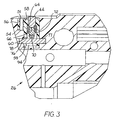
- FIG. 3 is a cross-sectional side elevation view of a portion of the housing of the underwater device of FIG. 1 showing a latch mechanism embodying features of the invention;
- FIG. 4 is an exploded perspective view of the latch mechanism of the underwater device of FIG. 1, showing a latch body and a latching/unlatching tool;
- FIG. 5 is a perspective view of the latch body of FIG. 4 after undergoing a force sufficient to break it before the housing is damaged; and
- FIGS. 6A and 6B are perspective views of another version of the invention showing a sacrificial retainer before and after fracture.
-
- An exemplary version of the
underwater device 20 embodying features of the invention is shown in FIGS. 1-5. The device depicted in FIG. 1 is a cable-leveling bird attached to astreamer cable 21. Thebird housing 22 includes a tubularmain body section 24 and afront pylon 26 and arear pylon 28. Two motor-drivenfins 30, or wings, extend from the main body section to control the depth of the cable. A pressure sensor in the front pylon is used to determine the depth of the bird so that the wings can be appropriately adjusted to maintain a desired depth. Thehousing 22 also contains the motor and other electronic components used to control the wings, read the pressure sensor, and communicate with a towing vessel over wires in thecable 21. The bird may also house a headingsensor 30, or digital compass, to provide a highly accurate indication of the orientation of the cable. The heading information relayed to the vessel is used to determine the shape of the cable during a seismic prospect. The calibrated heading sensor is accurately aligned in thehousing 22 along a headingaxis 32 aligned with the axis of the tubular main body section, which serves as the bird's heading reference axis. - Collar rings 34 are firmly clamped around the
cable 21 at front and rear mounting positions. The rings form an inner race to accommodate aconnector assembly 36, which can freely rotate about the ring and, hence, the cable. Although it does not have to be, the connector could be a hinged assembly with removable hinge pins 38, such as the Quick Latch™ collar assembly manufactured by DigiCOURSE, Inc. of Harahan, LA, or could be an unhinged, or other, assembly providing a means of attachment to the cable. As shown in FIG. 2, theconnector 36 includes areceptacle 40, in the shape of, for example, a keyhole with alarge opening 41 at one end and aslot 42 at the other end. A typical connector has a second similar receptacle 180° around its circumference to similarly accommodate another device, such as a flotation tube. Theconnector 36 is attached to the bird by a lockingmember 44, preferably a dovetail pin, extending from thepylons housing 22. To avoid redundancy, subsequent descriptions focus on the attachment to a mounting element at thefront pylon 26, but apply also to the attachment at therear pylon 28. Thepreferred locking pin 44 has a pair of opposite horizontal grooves 46 just below its top 48. The circumference of the top is just less than the circumference of thelarge opening 41 in thereceptacle 40. The opposing grooves are dimensioned to allow thelocking pin 44 to slide along theslot 42 in the receptacle to its end opposite the large opening. In this way the locking member engages the receptacle of the connector securely in a locked position. Alock screw 50 tightened into a threadedhole 51 in the pylon or other similar fastener offset along theslot 42 from the locking pin can be used to provide a more stable two-point retention of thepylon 26 to theconnector 36. - Further details of a preferred version of a
latch mechanism 52 are shown in FIGS. 3-4. Thehousing pylon 26 includes alatch cavity 54 sized to receive alatch insert body 56. The latch body has atop side 58 and an oppositebottom side 59. The top side faces the cable and is preferably flush with the pylon's upper surface. The latch body includes achamber 60 having anopening 62 in the top side through which the top 48 of the lockingpin 44 protrudes. The chamber wall forms acircumferential ledge 64 recessed into the latch body. The locking pin includes aregion 66 having a thinner diameter to accommodate a stack ofBelleville washers 68. The stack of washers is retained at the bottom by a dome-shapedplug 70 having acircumferential flange 72 to support the stack. When the lockingpin 44 is engaged with aconnector 36, the pin is pulled outward slightly in its locking position. The Belleville washers are compressed between theflange 72 and theledge 64 of thechamber 60. In this way they apply a biasing spring force acting to retract the pin back into the chamber and, consequently, holding the connector tightly to the top of thepylon 26. - The
latch body 56 preferably includes abore 74 through which aretainer 76, such as a set screw, can extend. Thehousing pylon 26 includes aligned threaded bores 77, 78, which the set-screw retainer engages. The retainer retains thelatch body 56 to the housing. The retainer can also serve to prevent the top of the lockingpin 44 from dropping below thetop side 58 of the latch body when the device is not engaged with aconnector 36 and theBelleville washer stack 68 is relaxed, allowing the pin to bottom out against the retainer. - An
access hole 79 formed in the front pylon 26 (and a similar access hole 79' in the rear pylon 26) extends into thelatch cavity 54. Anaccess aperture 80 formed in thelatch body 56 is aligned with the access hole to admit atool 82 into the lockingpin chamber 60. The inserted tool can be used to lift the lockingpin 44 up against spring pressure to an unlocked position for removing the bird from and installing it on aconnector 36. In removing birds, once the locking pin is clear of the receptacle, the tool can be removed from the access hole. In attaching birds, the tool can be removed once the locking pin is in its locked position at the end of the receptacle slot. A screwdriver or other such shafted tool can also be used. - One version of tool that works well is shown in FIG. 4. The
tool 82 has afirst shaft portion 84 and asecond shaft portion 85 forming an eccentric camming surface on the second shaft portion. Anend portion 86 of the tool is similar to the first portion, but includes aflat surface 87. The tool is inserted into thechamber 60 through the alignedaccess hole 79 andaccess aperture 80. Theflat surface 87 makes it easier for the tool to slip under the dome-shapedplug 70 at the bottom of the lockingpin 44. The tool is inserted until theeccentric portion 85 is under the dome-shaped plug. Theend portion 86 is supported by the walls of the access hole and aperture on the other side of the latch body. As the tool is rotated, the eccentric camming surface, which is eccentric relative to the first shaft portion and the end portion, engages the dome-shaped plug and raises and lowers the locking pin between unlocked and locked positions. The tool includes ahandle 88 for better leverage. This allows for easy deployment of devices on a streamer cable and eliminates the need for a costly eccentric cam to be built into each latch mechanism. - During collisions between birds and underwater debris or vessel structures, the impact typically imparts a force with a component in the direction of arrow 90 (FIG. 5) that tends to separate the bird from the cable. In many instances, the force can be so great that the housings of conventional birds or other cable-attached devices can be irreparably damaged This is especially true of devices that include a heading sensor, for which even relatively small distortions in the housings can cause intolerable alignment errors. As shown in the latch body version of FIG. 5, when the component of force 90 acting on the latch body increases above a predetermined level, a
thin portion 92 of the latch body around thebore 74 gives way under pressure from theretainer 76. Acting as a sacrificial element, the broken-away portion prevents the force of impact from reaching a level great enough to damage the rest of thehousing 22. The force required to break the sacrificial element can be taken into account in designing the part. For example, the thickness of the material around thebore 74 can be changed to withstand different levels of forces. As shown in FIG. 3, thebottom side 59 of the latch body can include a void 94 to lessen the amount of material around the bore subject to the pressure of the retainer. A variety of materials can be used to construct thelatch body 56 to tailor its failure loads and modes for different applications. Particularly suitable materials for the latch body include moldable plastics because of their versatililty, light weight, and corrosion-resistance, but other materials could also be used. It is also possible to use other parts of theoverall latch mechanism 52 as the sacrificial element. For example, as shown in FIGS. 6A and 6B, another version of aretainer 96 has afrangible region 97 that breaks under pressure from the walls of the surrounding bore 74 of thelatch body 56. The frangible region could be formed by a thinner diameter material, as shown, or by making the retainer out of a different material than a typical steel set screw, such as a plastic or ceramic or other more brittle or generally weaker material. - Once the sacrificial element gives way upon impact, the
bird 20 is still retained to thecable 21 by thelatch mechanism 52 at the other pylon or, in the event both latch mechanisms are sacrificed, by a lanyard (not shown) attached to thehousing 22 and looped around the cable. The bird merely has to be retrieved and the broken sacrificial latch mechanism replaced by a good one before returning to service. There is no need to replace the entire bird with another and send the damaged bird back to the factory for repair or disposal. - Although the invention has been described in detail with reference to preferred versions, other versions are possible. For example, the inner ring/outer connector assembly was used throughout as an exemplary mounting element for attaching devices to underwater cables. Other mounting elements that are engageable by a locking member extending between the mounting element and a latch body could equivalently be used. The locking pin need not be a dovetail pin as described. Other locking and latching schemes could be substituted for the dovetail/slot scheme described in the depicted versions. Hooks, clasps, and bolts are only a few of the locking elements that one could substitute for the dovetail pin described. The sacrificial element could be realized in other ways. The retainer need not extend all the way through the latch body and need not be a set screw. A shear pin or other frangible structure could be used to retain the latch body in normal operation and to yield under preselected levels of force acting on the latch body. It is clear that one skilled in the art would recognize many equivalent structures for attaching devices to underwater cables. Although the description used the cable-leveling bird as a exemplary cable-attached device, other devices, such as acoustic ranging devices, cable retrieval devices, flotation devices, and other sensing devices, could derive benefit from the features embodied in the described versions. The invention also has application on untowed bottom cables to which similar devices are attached.
Claims (6)
- A connector connectable to an underwater cable for connecting a device (20) to a mounting element (36) on the underwater cable, said connector comprising:characterised in that the engagement between the latch body (56) and the device housing (26) is sacrificially frangible to release the engagement of the latch body (56) with the housing (26) in response to force in excess of normal operating forces acting on the latch body.a latch body (56) having a locking member (44) for securing the latch body (56) to the mounting element (36);a retainer (76) for forming an engagement between the latch body and a housing (26) of the device (20);
- A connector as claimed in claim 1 wherein a portion (92) of the latch body (56) is sacrificially frangible to release the engagement.
- A connector according to claim 2 wherein the latch body has a bore (74) and the retainer (76) extends through the bore (74) and wherein a portion (92) of the latch body around the bore (74) is sacrificially frangible.
- A connector according to claim 1 wherein the retainer is sacrifically frangible.
- A connector according to any one of the preceding claims wherein the latch body (56) is insertable into a cavity (54) in the housing (26) of the device (20).
- A connector according to claim 5 wherein, in use, the retainer (76) extends through a bore (74) in the latch body (56) into the wall of the housing (26).
Applications Claiming Priority (2)
| Application Number | Priority Date | Filing Date | Title |
|---|---|---|---|
| US08/950,827 US5937782A (en) | 1997-10-15 | 1997-10-15 | Underwater device with a sacrificial latch mechanism |
| US950827 | 1997-10-15 |
Publications (3)
| Publication Number | Publication Date |
|---|---|
| EP0909701A2 EP0909701A2 (en) | 1999-04-21 |
| EP0909701A3 EP0909701A3 (en) | 2001-04-11 |
| EP0909701B1 true EP0909701B1 (en) | 2003-01-08 |
Family
ID=25490895
Family Applications (1)
| Application Number | Title | Priority Date | Filing Date |
|---|---|---|---|
| EP98308154A Expired - Lifetime EP0909701B1 (en) | 1997-10-15 | 1998-10-07 | Underwater device with a sacrificial latch mechanism |
Country Status (6)
| Country | Link |
|---|---|
| US (1) | US5937782A (en) |
| EP (1) | EP0909701B1 (en) |
| AU (1) | AU748051B2 (en) |
| CA (1) | CA2249950C (en) |
| DE (1) | DE69810567T2 (en) |
| NO (1) | NO329375B1 (en) |
Cited By (2)
| Publication number | Priority date | Publication date | Assignee | Title |
|---|---|---|---|---|
| US8792297B2 (en) | 2010-07-02 | 2014-07-29 | Pgs Geophysical As | Methods for gathering marine geophysical data |
| US9395458B2 (en) | 1996-12-20 | 2016-07-19 | Westerngeco, L.L.C. | Control devices for controlling the position of a marine seismic streamer |
Families Citing this family (15)
| Publication number | Priority date | Publication date | Assignee | Title |
|---|---|---|---|---|
| GB9821277D0 (en) | 1998-10-01 | 1998-11-25 | Geco As | Seismic data acquisition equipment control system |
| US6011752A (en) * | 1998-08-03 | 2000-01-04 | Western Atlas International, Inc. | Seismic streamer position control module |
| US6691038B2 (en) | 2001-06-15 | 2004-02-10 | Westerngeco L.L.C. | Active separation tracking and positioning system for towed seismic arrays |
| US7310287B2 (en) * | 2003-05-30 | 2007-12-18 | Fairfield Industries Incorporated | Method and apparatus for seismic data acquisition |
| US7450467B2 (en) | 2005-04-08 | 2008-11-11 | Westerngeco L.L.C. | Apparatus and methods for seismic streamer positioning |
| US8348543B2 (en) * | 2009-03-23 | 2013-01-08 | Ion Geophysical Corporation | Streamer connection system |
| EP2743736A1 (en) * | 2012-12-17 | 2014-06-18 | Sercel | Tail device connectable to a tail of a towed acoustic linear antenna cooperating with a set of at least one depth control means. |
| US9360575B2 (en) | 2013-01-11 | 2016-06-07 | Fairfield Industries Incorporated | Simultaneous shooting nodal acquisition seismic survey methods |
| US9423519B2 (en) | 2013-03-14 | 2016-08-23 | Pgs Geophysical As | Automated lateral control of seismic streamers |
| EP2857868B1 (en) * | 2013-10-07 | 2018-12-05 | Sercel | Wing releasing system for a navigation control device |
| US11041973B2 (en) * | 2015-11-17 | 2021-06-22 | Fairfield Industries Incorporated | Back deck automation |
| AU2018273225A1 (en) | 2017-05-23 | 2020-01-16 | Ion Geophysical Corporation | Seismic node deployment system |
| CN112203932B (en) | 2018-06-08 | 2024-03-22 | 离子地球物理学公司 | Sensor node attachment mechanism and cable retrieval system |
| EP3821280A1 (en) * | 2018-07-10 | 2021-05-19 | ION Geophysical Corporation | Latch mechanism for seismic streamer device |
| CN109649616A (en) * | 2019-01-08 | 2019-04-19 | 天长市未名机器人有限责任公司 | Underwater fish bionic fish tail |
Family Cites Families (11)
| Publication number | Priority date | Publication date | Assignee | Title |
|---|---|---|---|---|
| US3931608A (en) * | 1974-04-25 | 1976-01-06 | Syntron, Inc. | Cable depth control apparatus |
| US4290124A (en) * | 1978-11-01 | 1981-09-15 | Syntron, Inc. | Remote control cable depth control apparatus |
| US4222340A (en) * | 1978-11-01 | 1980-09-16 | Syntron, Inc. | Cable depth control apparatus |
| AU548339B2 (en) * | 1981-07-31 | 1985-12-05 | Edo Western Corporation | Towing under-water vehicle |
| US4586452A (en) * | 1981-07-31 | 1986-05-06 | Edo Western Corporation | Underwater tow system and method |
| US4711194A (en) * | 1982-11-24 | 1987-12-08 | The Laitram Corporation | Streamer interface adapter cable mounted leveler |
| US4709355A (en) * | 1984-06-18 | 1987-11-24 | Syntron, Inc. | Controller for marine seismic cable |
| US4879719A (en) * | 1988-02-17 | 1989-11-07 | Western Atlas International, Inc. | Latching mechanism |
| US5214612A (en) * | 1992-07-27 | 1993-05-25 | The Laitram Corporation | Swing plate latch mechanism |
| US5529011A (en) * | 1994-02-23 | 1996-06-25 | Laitram Corporation | Connector for underwater cables |
| US5507243A (en) | 1994-02-23 | 1996-04-16 | The Laitram Corporation | Connector for underwater cables |
-
1997
- 1997-10-15 US US08/950,827 patent/US5937782A/en not_active Expired - Lifetime
-
1998
- 1998-10-07 DE DE69810567T patent/DE69810567T2/en not_active Expired - Lifetime
- 1998-10-07 EP EP98308154A patent/EP0909701B1/en not_active Expired - Lifetime
- 1998-10-13 AU AU89264/98A patent/AU748051B2/en not_active Expired
- 1998-10-14 NO NO19984785A patent/NO329375B1/en not_active IP Right Cessation
- 1998-10-14 CA CA002249950A patent/CA2249950C/en not_active Expired - Lifetime
Cited By (2)
| Publication number | Priority date | Publication date | Assignee | Title |
|---|---|---|---|---|
| US9395458B2 (en) | 1996-12-20 | 2016-07-19 | Westerngeco, L.L.C. | Control devices for controlling the position of a marine seismic streamer |
| US8792297B2 (en) | 2010-07-02 | 2014-07-29 | Pgs Geophysical As | Methods for gathering marine geophysical data |
Also Published As
| Publication number | Publication date |
|---|---|
| DE69810567T2 (en) | 2003-09-25 |
| CA2249950A1 (en) | 1999-04-15 |
| NO984785D0 (en) | 1998-10-14 |
| EP0909701A3 (en) | 2001-04-11 |
| NO329375B1 (en) | 2010-10-04 |
| AU8926498A (en) | 1999-05-06 |
| EP0909701A2 (en) | 1999-04-21 |
| AU748051B2 (en) | 2002-05-30 |
| CA2249950C (en) | 2006-05-02 |
| DE69810567D1 (en) | 2003-02-13 |
| NO984785L (en) | 1999-04-16 |
| US5937782A (en) | 1999-08-17 |
Similar Documents
| Publication | Publication Date | Title |
|---|---|---|
| EP0909701B1 (en) | Underwater device with a sacrificial latch mechanism | |
| US4290124A (en) | Remote control cable depth control apparatus | |
| EP0884607A2 (en) | Depth control device for an underwater cable | |
| US20040251048A1 (en) | Modular design for LWD/MWD collars | |
| US4222340A (en) | Cable depth control apparatus | |
| EA027580B1 (en) | Ocean bottom seismic cable recording apparatus | |
| US8348543B2 (en) | Streamer connection system | |
| AU689186B2 (en) | Connector for underwater cables | |
| US7586809B2 (en) | Underwater sensor and data sensing and recording apparatus | |
| AU622652B2 (en) | Latching mechanism | |
| EP3140508A2 (en) | Method for deploying a retrievable mwd tool in a non-retrievable environment | |
| US4610309A (en) | Downhole tool | |
| US20180106921A1 (en) | Removable fastening mechanism for marine deployment of autonomous seismic nodes | |
| US6263823B1 (en) | Connection system for connecting equipment to underwater cables | |
| US11092278B2 (en) | Cable attachment system | |
| EP1604226B1 (en) | Coupling aid for seismic cable | |
| US20230089102A1 (en) | A device for monitoring strain of an elongate underwater member | |
| US4892445A (en) | Man portable shallow water structure | |
| US6525991B2 (en) | Coupling device to attach auxiliary equipment to a marine seismic cable | |
| WO2017063985A1 (en) | Multi component sensor device for point measurements on the seabed during seismic surveys | |
| WO2020208424A1 (en) | Ocean bottom node with removable acoustic pinger | |
| US20230146618A1 (en) | Pop-up seabed seismic node | |
| EP3140496B1 (en) | Orienting hanger assembly for deploying mwd tools | |
| WO2021165668A1 (en) | Buoyancy module | |
| Prothero Jr et al. | Advanced Marine Technology: Benthic Array |
Legal Events
| Date | Code | Title | Description |
|---|---|---|---|
| PUAI | Public reference made under article 153(3) epc to a published international application that has entered the european phase |
Free format text: ORIGINAL CODE: 0009012 |
|
| AK | Designated contracting states |
Kind code of ref document: A2 Designated state(s): DE FR GB NL |
|
| AX | Request for extension of the european patent |
Free format text: AL;LT;LV;MK;RO;SI |
|
| PUAL | Search report despatched |
Free format text: ORIGINAL CODE: 0009013 |
|
| AK | Designated contracting states |
Kind code of ref document: A3 Designated state(s): AT BE CH CY DE DK ES FI FR GB GR IE IT LI LU MC NL PT SE |
|
| AX | Request for extension of the european patent |
Free format text: AL;LT;LV;MK;RO;SI |
|
| RIC1 | Information provided on ipc code assigned before grant |
Free format text: 7B 63B 21/66 A, 7F 16B 21/00 B, 7B 63G 8/42 B, 7F 16B 31/00 B, 7G 01V 1/38 - |
|
| RAP1 | Party data changed (applicant data changed or rights of an application transferred) |
Owner name: INPUT/OUTPUT, INC. |
|
| 17P | Request for examination filed |
Effective date: 20010905 |
|
| 17Q | First examination report despatched |
Effective date: 20011122 |
|
| AKX | Designation fees paid |
Free format text: DE FR GB NL |
|
| GRAG | Despatch of communication of intention to grant |
Free format text: ORIGINAL CODE: EPIDOS AGRA |
|
| GRAG | Despatch of communication of intention to grant |
Free format text: ORIGINAL CODE: EPIDOS AGRA |
|
| GRAH | Despatch of communication of intention to grant a patent |
Free format text: ORIGINAL CODE: EPIDOS IGRA |
|
| GRAH | Despatch of communication of intention to grant a patent |
Free format text: ORIGINAL CODE: EPIDOS IGRA |
|
| GRAA | (expected) grant |
Free format text: ORIGINAL CODE: 0009210 |
|
| AK | Designated contracting states |
Kind code of ref document: B1 Designated state(s): DE FR GB NL |
|
| REG | Reference to a national code |
Ref country code: GB Ref legal event code: FG4D |
|
| REF | Corresponds to: |
Ref document number: 69810567 Country of ref document: DE Date of ref document: 20030213 Kind code of ref document: P |
|
| ET | Fr: translation filed | ||
| PLBE | No opposition filed within time limit |
Free format text: ORIGINAL CODE: 0009261 |
|
| STAA | Information on the status of an ep patent application or granted ep patent |
Free format text: STATUS: NO OPPOSITION FILED WITHIN TIME LIMIT |
|
| 26N | No opposition filed |
Effective date: 20031009 |
|
| PGFP | Annual fee paid to national office [announced via postgrant information from national office to epo] |
Ref country code: DE Payment date: 20131002 Year of fee payment: 16 |
|
| REG | Reference to a national code |
Ref country code: DE Ref legal event code: R119 Ref document number: 69810567 Country of ref document: DE |
|
| PG25 | Lapsed in a contracting state [announced via postgrant information from national office to epo] |
Ref country code: DE Free format text: LAPSE BECAUSE OF NON-PAYMENT OF DUE FEES Effective date: 20150501 |
|
| REG | Reference to a national code |
Ref country code: FR Ref legal event code: PLFP Year of fee payment: 19 |
|
| REG | Reference to a national code |
Ref country code: FR Ref legal event code: PLFP Year of fee payment: 20 |
|
| PGFP | Annual fee paid to national office [announced via postgrant information from national office to epo] |
Ref country code: FR Payment date: 20170918 Year of fee payment: 20 |
|
| PGFP | Annual fee paid to national office [announced via postgrant information from national office to epo] |
Ref country code: NL Payment date: 20171016 Year of fee payment: 20 Ref country code: GB Payment date: 20171004 Year of fee payment: 20 |
|
| REG | Reference to a national code |
Ref country code: NL Ref legal event code: MK Effective date: 20181006 |
|
| REG | Reference to a national code |
Ref country code: GB Ref legal event code: PE20 Expiry date: 20181006 |
|
| PG25 | Lapsed in a contracting state [announced via postgrant information from national office to epo] |
Ref country code: GB Free format text: LAPSE BECAUSE OF EXPIRATION OF PROTECTION Effective date: 20181006 |