EP0909416B1 - Method and apparatus for providing improved diagnostic functions in a computer system - Google Patents
Method and apparatus for providing improved diagnostic functions in a computer system Download PDFInfo
- Publication number
- EP0909416B1 EP0909416B1 EP97932317A EP97932317A EP0909416B1 EP 0909416 B1 EP0909416 B1 EP 0909416B1 EP 97932317 A EP97932317 A EP 97932317A EP 97932317 A EP97932317 A EP 97932317A EP 0909416 B1 EP0909416 B1 EP 0909416B1
- Authority
- EP
- European Patent Office
- Prior art keywords
- bios
- memory
- processes
- flash memory
- computer
- Prior art date
- Legal status (The legal status is an assumption and is not a legal conclusion. Google has not performed a legal analysis and makes no representation as to the accuracy of the status listed.)
- Expired - Lifetime
Links
Images

Classifications
-
- G—PHYSICS
- G06—COMPUTING; CALCULATING OR COUNTING
- G06F—ELECTRIC DIGITAL DATA PROCESSING
- G06F11/00—Error detection; Error correction; Monitoring
-
- G—PHYSICS
- G06—COMPUTING; CALCULATING OR COUNTING
- G06F—ELECTRIC DIGITAL DATA PROCESSING
- G06F11/00—Error detection; Error correction; Monitoring
- G06F11/22—Detection or location of defective computer hardware by testing during standby operation or during idle time, e.g. start-up testing
Definitions
- This invention relates to computer systems and, more particularly, to methods and apparatus for utilizing a flash EEPROM memory array supplementing main memory to provide diagnostic functions.
- flash electrically-erasable programmable read-only memory (EEPROM) storage devices have been used in arrays as a new form of long term storage.
- a flash EEPROM memory array is constructed of a large plurality of floating-gate metal-oxide-silicon field effect transistor devices arranged as memory cells in typical row and column fashion with circuitry for accessing individual cells and placing the memory transistors of those cells into different memory conditions.
- Such memory transistors may be programmed by storing a charge on the floating gate. This charge remains when power is removed from the array.
- a charge typically indicates a "zero" or programmed condition, while the absence of a charge indicates a "one" or erased condition.
- the floating gate condition may be detected when the device is read.
- Flash memory is being used to replace various read-only memories such as the basic input/output startup (BIOS) memory of a computer system.
- BIOS basic input/output startup
- flash memory has been used to provide a smaller lighter functional equivalent of an electro-mechanical hard disk drive. Flash memory is useful for this purpose because it may be read more rapidly and is not as sensitive to physical damage as an electro-mechanical hard disk drive. Flash hard drive memories are especially useful in portable computers where space is at a premium and weight is extremely important.
- flash memory can be used to store rapidly changing data
- a number of difficult problems which are related to the design of flash memory must be solved.
- a flash memory array is divided into blocks which are connected so that all of the memory cells of an entire block are erased simultaneously. Thereafter, a cell may be individually programmed to store data. Since all of the memory transistors of a block of the array are joined to be erased together, a cell in a programmed condition cannot be switched to the erased state until the entire block of the array is erased. Thus, invalid information cannot be erased without erasing also all of the valid information that remains in the block.
- a flash EEPROM memory array requires a time consuming erasure process before it may be rewritten.
- the new information is written to a new memory area rather than over the old information; and the old information is marked as invalid.
- all valid information remaining in the block is written to a clean memory area; and the entire block may then be erased, often by a background process.
- flash memory may be read at the same rate as dynamic random access memory (DRAM) manufactured by the same processes so it would seem that flash memory might be used to replace or supplement main memory.
- DRAM dynamic random access memory
- flash memory might be used to replace or supplement main memory.
- DRAM dynamic random access memory
- the level of charge required to write a flash device is much greater, writing to flash memory takes somewhat longer than writing to DRAM.
- changed data may not be directly written over invalid data in a block of flash memory but must be written to a new area, the old data invalidated, and the block with invalid data ultimately erased, the average time to write to flash memory is very much longer than to write to DRAM.
- flash memory has been used for many purposes in computer systems, it has not been used as main memory or a supplement to main memory.
- the write time for flash memory has been considered to be too long to allow the use of flash memory as a part of main memory.
- BIOS basic input/output start-up
- BIOS processes in the flash read-only memory on the X bus are read and transferred via the ISA bus (or other secondary bus), an ISA/PCI bridge, the PCI bus, and a PCI-to-processor/memory bridge to main memory.
- US-A-5,522,076 discloses a flash memory, connected to a system bus, used as a BIOS-ROM, including a main block storing a BIOS and a boot block storing minimum programs for execution in initialising a computer system.
- the BIOS ROM may be updated or re-written from a boot block rewriting unit connected to an expansion bus connector of the computer system or from a floppy disc, the floppy disk or boot block rewriting unit containing a rewriting program and a copy of the BIOS and boot block.
- US-A-5,530,847 discloses a non-volatile memory, preferably a flash memory, as part of a memory subsystem connected to a generic bus, the non-volatile memory being for storing a boot-loading routine, a decompression routine, a compressed driver routine and a compressed diagnostic routine.
- the compressed driver and diagnostic routine are decompressed into video RAM by the decompression routine to facilitate testing, inter alia, system RAM.
- the driver routine provides an environment in lieu of an operating system in which to execute the diagnostic routine in the video RAM.
- the diagnostics are therefore performed without use of BIOS hardware handling routines provided by an operating system.
- the diagnostics are performed optionally, and not as part of a normal boot of a PC.
- BIOS processes in a flash EEPROM memory array which resides on the memory bus as a supplement to main memory would also offer another significant advantage.
- the BIOS includes various processes which test the condition of various components of the computer system. These BIOS processes are useful to one servicing a computer in the event of a failure. However, if the computer has problems which make it impossible to write the BIOS processes to main memory, the BIOS processes cannot be used in determining the nature of the problem. If these processes could somehow be made available in permanent memory on the memory bus, then even though the computer was otherwise inoperative, discovering the source of problems would be much easier.
- the present invention is realized by a flash EEPROM memory array designed to be joined to a memory bus of a computer, diagnostic processes stored in the array for testing status of system to provide data indicating malfunctions in the computer, accessing processes stored in the array for calling the diagnostic processes even though the computer fails to boot, and communication processes stored in the array for transferring results produced by the diagnostic processes for use in servicing the computer.
- One embodiment of the invention allows the transfer of data between hardware components of a computer and an external host computer so that a service technician at the host computer may diagnose and correct malfunctions within the computer which includes the flash EEPROM memory array.
- the manipulations performed are often referred to in terms, such as adding or comparing, which are commonly associated with mental operations performed by a human operator. No such capability of a human operator is necessary or desirable in most cases in any of the operations described herein which form part of the present invention; the operations are machine operations.
- Useful machines for performing the operations of the present invention include general purpose digital computers or other similar devices. In all cases the distinction between the method operations in operating a computer and the method of computation itself should be borne in mind.
- the present invention relates to a method and apparatus for operating a computer in processing electrical or other (e.g. mechanical, chemical) physical signals to generate other desired physical signals.
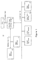
- the system 10 illustrated includes a central processing unit 11 which executes the various instructions provided to control the operations of the system 10.
- the central processing unit 11 is typically joined by a processor bus to a bridge circuit 14 which controls access to an input/output bus 12 adapted to carry information between the various components of the system 10.
- the bus 12 is preferably a peripheral component interface (PCI) bus or other local bus adapted to provide especially fast transfers of data.
- PCI peripheral component interface
- This bus is chosen in Figure 1 for illustrative purposes only.
- various input/output devices are connected to the bus 12 as bus master and bus slave circuits.
- long term memory 15 may be joined to the PCI bus 12 as a bus master or a bus slave circuit.
- Other input/output devices such as sound boards, frame buffers, and the like may also be joined to the bus 12.
- the bridge circuit 14 is also joined by a memory bus 16 to main memory 13.
- Main memory 13 is typically constructed of dynamic random access memory arranged in a manner well known to those skilled in the prior art to store information during a period in which power is provided to the system 10 although some systems may use other forms of random access memory such as static random access memory to accomplish the same purpose.
- a flash EEPROM memory array 17 designed in accordance with the present invention is also positioned on the memory bus 16 with main memory 13.
- a second flash EEPROM memory array 17 designed in accordance with the present invention is positioned on the bus 12 as well to demonstrate a second position.
- flash memory has been considered to be unsuitable for storing programs and processes which involve frequent write operations.
- write times are long compared to write times for DRAM, there are a number of reasons to use flash EEPROM memory arrays to supplement main memory.
- One primary reason is to provide programs and processes which are immediately available for execution by the central processing unit when power is applied to a computer. If a flash EEPROM memory array is positioned on the memory bus so that it may be accessed as rapidly as the DRAM of main memory, and if an application program is placed in and made executable from the flash EEPROM memory array, then the application program need not be called from long term memory and placed in main memory in order to run. Similarly, if an executable application program stored in a flash EEPROM memory array positioned on a bus such as a PCI bus, the application may be run from the flash memory and need not be placed in main memory DRAM in order to run. This allows programs to begin functioning more rapidly and essentially eliminates page swapping for applications stored in the flash memory.
- BIOS processes typically create data structures defining hardware elements of the computer system.
- the memory addresses assigned to the flash memory are designated as read and execute only. This allows an executable program stored in flash EEPROM memory array to be read and executed in a normal manner. However, if an attempt is made to write to the flash EEPROM memory array, an exception is generated because this area of the flash EEPROM memory array is read and execute only.
- a special exception handler is called which causes the memory management unit to read the page which includes the address to which the write was attempted and to write the data to DRAM memory.
- the page table for that portion of the program is updated so that accesses addressed to that portion of the program arc now addressed to DRAM memory from which the program data may be read, written, and executed.
- the data in that portion of the program whether data structures, variables, or self-modifying code, may be modified by writing to the page in DRAM main memory.
- any program or process stored in a flash EEPROM memory array positioned on the memory bus or a local bus may run even though the program or process contains an area which must be written during operation.
- the present invention makes use of such an arrangement which allows programs to be executed directly from flash memory to make the execution of BIOS programs which write various data structures feasible. If the flash memory is placed on the memory bus, processes may be accessed if operative DRAM memory exist even though the computer is inoperative. By storing the BIOS processes in flash memory positioned to supplement main memory DRAM on the memory bus, the BIOS processes may be accessed even though the computer system is unable to read data cross the PCI and ISA buses. In fact, since the BIOS processes are in flash memory supplemental main memory when power is applied, they are immediately accessed.
- the invention allows the system test processes which are a part of the BIOS processes or any other test processes stored in flash memory to be used to determine the status of the system hardware.
- the invention allows hardware problems to be diagnosed and cured even though the operating system cannot be invoked.
- the invention provides the ability to furnish more hardware status data to a user (or via modem to a service technician) and allows a user (or technician) to manipulate the hardware of the system in order to diagnose and often overcome malfunctions.
- the executable diagnostic processes may still be accessed even though the computer system is unable to read data across the secondary bus so long as the path across the PCI bus remains intact.
- the set of BIOS test routines provided with a computer system are typically designed only to return values indicating the state of the components of the system which are normally used to set up the computer when it is started. Many of these values are only useful in diagnosing hardware problems to a technically skilled person and may be accessed only if special hardware is included in the computer. Even such a person may require additional diagnostic routines of substantial sophistication to give the values any diagnostic meaning. Because most users are insufficiently skilled to understand the results provided by a diagnostic program, most manufacturers do not provide diagnostic processes with the computers they sell. Consequently, the values generated by the BIOS processes are not very useful to most users in diagnosing hardware problems. In any case, the results produced by presently available BIOS test processes are not available if the system will not boot an operating system. This has made maintaining and repairing computers very expensive.
- manufacturers provide warranty service for from one to three years after purchase of a computer.
- a user calls a designated telephone number for service when a problem occurs with a machine under warranty. This usually starts a stumbling process by which a technician first determines the extent of the user's understanding and then talks the user through various steps to determine whatever facts are available. Often, the problem is not solved in this manner; and the user or a service technician must take the machine to a service facility for repair or have a technician make a housecall to fix the problem.
- the costs for service of this type have mounted with each improvement in the capabilities of personal computers.
- the supplementary diagnostic processes run automatically if a failure occurs during start up and provide an indication to the user that a problem exists and the steps the user should take. These may include calling the service technician to explain the problem and the results shown by the diagnostic processes, or connecting to the service technician via a modem or network connection. The latter would allow a technician to run tests by means of such a connection using the diagnostic processes available on the machine with the problem and possibly curing the problem through the use of software processes available through the system used by the technician.
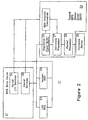
- FIG 2 is a block diagram of a software system designed in accordance with the present invention.
- the system includes a BIOS driver kernel 21 and a plurality of BIOS device drivers 2.3 each of which is stored in flash EEPROM memory array (such as the array 17 shown in Figure 1) on the memory bus of a computer.
- the kernel 21 and the drivers 23 may be a part of the BIOS functions stored in the flash memory or separate therefrom although stored in the same flash memory.
- the kernel 21 and each of the device drivers are adapted to function even though the operating system of the computer cannot be booted so that they may be used to diagnose and correct the functions of the computer.
- An understanding manner in which the kernel and the device drivers function will be assisted by referring to Figure 3 along with the description which follows.
- BIOS processes stored in the flash memory are called; and the boot of the system begins. If the system functions correctly, the operating system is ultimately loaded; and the system is placed in operating condition. If the system does not boot, the BIOS and other diagnostic processes are available in flash memory on the memory bus and may be utilized in the absence of the typical operating system.
- the BIOS diagnostic processes are invoked by a system boot failure and may indicate the failure to a user and suggest that the user call the diagnostic processes by selecting a screen option.
- the BIOS diagnostic processes may indicate the failure to the user and automatically switch to and run the diagnostics processes in an attempt to fix the problem. In either case, the presence of the supplemented diagnostic processes in memory allows a user or a technician to operate diagnostic processes included in the flash memory for diagnosing hardware problems even though the system will not boot.
- the kernel 21 has only a few very simple functions which it can carry out by itself. It may use kernel I/O services processes 24 to request keyboard, disk, or video input/output to allow a user to manipulate the system in the absence of these functions normally provided by the operating system. In one embodiment, these processes call the standard BIOS processes for accomplishing these functions. However, the main function of the kernel 21 is to provide a series of kernel service processes 25 which may be operated to provide services for the plurality of BIOS device drivers 23. In general, the kernel services processes 25 include processes which facilitate the transfer of data from which diagnoses may be made, both among the system components and external to the system.
- Each BIOS device driver 23 (only one is shown in detail) is typically associated with a particular input/output hardware device 29. Such a driver is typically written by the manufacturer or service provider of the particular hardware device and contains processes for use with that hardware device.
- Each device driver 23 provides a dispatcher process 26 which furnishes a standard interface for interaction by the particular device driver 23 with the kernel services processes 25.
- the kernel services processes 25 may address a device driver 23 by directing a command to the dispatcher process 26.
- one of the kernel services processes 25 polls in serial order the dispatcher processes 26 of each of the BIOS device drivers 23 which are provided to request commands from the drivers 23.
- a dispatcher process 26 responds to a request for a command from the kernel by providing commands for the kernel services processes 25 to execute.
- Each device driver 23 includes a limited set of functions which it may command the kernel 21 to execute.
- the dispatcher process 26 receives the command functions to execute from a command processor 27.
- the command processor 27 translates commands furnished from an associated hardware device 29 into commands that the kernel services processes 25 understand so that the kernel, may execute the limited set of commands available to it.
- the dispatcher process 26 transfers the commands into a command buffer accessible by the kernel. Typically such a buffer will be a data structure set up by the kernel in random access memory and identified by the calling parameters.
- Each of the device drivers 23 also includes a packet processor 28 which communicates directly with the hardware device 29 and (depending on the device 29) receives packets from the hardware device 29 for transfer to the command processor 27.
- the packet processor 28 parses these packets and passes the data to the command processor 27.
- the command processor 27 translates the data into raw function commands and notifies the dispatcher 26 that a command is available.
- the kernel services processes 25 poll the dispatcher 26 to determine whether that device driver 23 has a command to be executed, the dispatcher 26 loads the command buffer with the command and passes the command to the kernel for execution.
- the kernel service processes 25 set up data structures which include the addresses of the various low level services offered by the kernel through its I/O services processes, a database of the BIOS diagnostic drivers 23 which exist, and the addresses of the dispatchers 26 for the drivers 23.
- the kernel may also maintain data structures defining stacks and data areas for the transfer of commands and data.
- a process causes the search of the data base of the BIOS diagnostic drivers 23 to determine which BIOS diagnostic drivers exist and the addresses of the dispatcher processes 26 for the drivers. Then, the kernel services processes 25 send an Initialize command to set up each device driver 23.
- each dispatcher 26 furnishes data defining the BIOS device driver 23 to the data structure maintained by the kernel services processes 25. This data may include the requirements of the BIOS device driver 23 for data, stack, code, and interrupts and may also include other data necessary for operating the BIOS device driver 23 and the associated hardware 29.
- the dispatcher process 26 may also cause the initialization of the hardware 29 (such as a modem) with which the BIOS device driver 23 is associated so that the hardware 29 may be operated.
- the kernel services processes 25 poll the dispatcher of each of the BIOS device drivers 23.
- the kernel services processes 25 may also send a GetStatus command to each of the BIOS device drivers 23 to determine the status of the hardware 29 associated with the BIOS device driver 23.
- the GetStatus command causes the dispatcher 26 to determine the physical characteristics of the hardware 29 so that problems with the hardware may be discovered and data indicating the status returned to the kernel.
- Each of the device drivers 23 may include internal diagnostic processes specially designed by a manufacturer or equipment supplier which may be initiated by a user to secure status data in response to a GetStatus command to assist in determining where a problem exists and how to resolve the problem.
- the kernel services processes 25 the user provides access to these diagnostic processes of each device driver 23.
- the driver 23 uses these internal diagnostic processes to run extensive testing to determine malfunctions and to provide diagnostic suggestions.
- the diagnostic processes may also include processes which attempt to correct problems which are discovered.
- the kernel services processes 25 may also send a Connect command to any of the BIOS device drivers 23 to cause the hardware 29 associated with a particular driver 23 to be connected to an external host.
- the connection process is typically isolated from the kernel and stored as special commands in a part of the BIOS device driver 23 shown as BDD internal commands in Figure 2.
- the dispatcher 26 for a modem device driver receives the connect command, it may run a process from the BDD internal processes which establishes a connection to a service technician at a host computer kept at the facilities of a manufacturer of a portion of the computer displaying problems in response to the diagnostic processes.
- the dispatcher 26 of the BIOS device driver 23 should return a value to the kernel indicating the results of the attempt such as: connection established, busy, device not present, connection timeout, or the like. This command allows the computer to be connected to a service technician who may then determine the problems which exist with the computer from some remote position.
- the kernel may send a PutDataStream command to cause a BIOS device driver 23 to transfer data to a host by modem or by LAN connection.
- a similar GetDataStream command from the kernel to a BIOS device driver 23 allows the kernel to get data from a BIOS device driver for transfer to some other portion of the computer system to correct malfunctions.
- a BIOS device driver 23 may request the kernel to transfer system status data to the requesting BIOS device driver 23 through the use of a GetSystemStatus command directed to the kernel. Similarly a GetSystemInfo command directed to the kernel will cause the kernel to transfer system information to the requesting BIOS device driver 23.
- a PutString command from a BIOS device driver 23 causes the kernel I/O services processes 24 to send a string of data to a video terminal for display to a user.
- An Exit command to the kernel will initiate a process to prompt the user to reboot once the malfunction has been corrected.
- a ReadSector command may be used to cause the kernel to read data from a storage drive for testing; and a WriteSector command may be used to replace data with data furnished from a host system or nonvolatile storage.
- a typical process illustrated in Figure 3 may proceed in the following manner.
- the BIOS power- on initialization process is activated; and transfers execution to the diagnostics kernel to initiate a series of basic system tests.
- these might be as simple as running the BIOS status tests which have been used historically.
- the kernel may determine the amount of random access memory available, whether the memory is working, and whether code can be executed. Presuming that the system passes these tests, then the operating system is automatically booted; and the system operates.
- the kernel services processes 25 may also, or alternatively, ask each of the hardware device drivers 23 to conduct a more extended set of diagnostic tests which return status values to assure that the various devices are functioning appropriately. For example, these tests may return the status of system settings and the various peripherals such as rotating disks, keyboard, video, network connections, and modems. The results of each set of diagnostic tests are logged as they occur. The kernel then passes to a next status determination and logs the results of that test. In a similar manner, if the devices 29 pass these tests, then the operating system is automatically booted; and the system operates.
- the kernel services processes 25 Before the kernel services processes 25 can cause the device drivers 23 to run any diagnostic processes, a series of operations are conducted in the manner shown in Figure 4.
- the kernel services processes 25 first determine what system resources are available and what each device driver 23 requires to conduct its tests. For example, a particular driver 23 may require two megabytes of random access memory while another requires a single megabyte of memory. After determining the extent of resources available, the kernel services processes 25 set up the data structures mentioned above such as those in which I/O services, device drivers, and dispatcher addresses are recorded. Then the addresses of the dispatcher processes 26 of the drivers 23 are determined, and each of the drivers 23 is initialized. The kernel services processes 25 then poll the drivers 23 sequentially to receive commands. At this point the kernel services processes 25 may send a GetStatus command to the drives 23 to initiate processes to determine the status of the associated devices 29.
- the operating system is automatically booted; and the system operates.
- the particular driver 23 may direct the kernel to display a message explaining the failure, possibly suggesting solutions to the problem, and asking if the user wants to attempt to fix the problem.
- one of the device drivers 23 may be designed to conduct tests to determine the status of an electromechanical hard disk drive. This device driver 23 may execute various basic diagnostic routines including reading the master partition table. In reading the partition table, the driver 23 may determine that an entry has been corrupted. The device driver 23 responds to this determination by directing the kernel I/O services processes 24 to indicate the problem to the viewer and possibly suggests solutions.
- the kernel invokes the diagnostic setup program a second time.
- the kernel services processes 25 may direct each of the device drivers 23 to conduct more extensive tests of system devices to determine in detail the condition of the associated hardware device. The particular processes run by the device drivers 23 will depend of the specific implementation provided by the manufacturer.
- results of these more extensive tests might produce a number of different results.
- the driver might cause the kernel to print on the display, "Disk drive failure. Would you like to attempt to fix?" A "no" answer would cause an exit from the diagnostics processes.
- a "yes” answer might cause the driver to run a process which might then offer the user the option of shutting down the computer and replacing the operating system from an archived copy.
- Other diagnostic processes might offer a user the option of going online with a software manufacturer to have various software replaced. If such an option were to be selected, the particular driver would call the kernel to run the Connect command to connect to the operating system manufacturer using data stored in the device driver for the modem. Once the connection were made to the manufacturer, a technician could utilize the various commands available to the kernel and to the device drivers to interrogate the hard drive and determine the problem with the operating system. For example, a technician might look at a drive using the ReadSector commands of the driver, and then transfer data read back to the host using the PutDataStream command.
- a corrected version might be placed in the drive using the GetDataStream command which allows the kernel to get data from a BIOS device driver for transfer to the drive.
- the WriteSector command to the kernel would then place the new version of the software in the drive. Again the operation would be completed by an Exit command to the kernel causing the display to ask for a reboot. It should be noted that this facility could be used to update and replace versions of the diagnostic processes in each of the device drivers 23.
- diagnostic processes might be made available through the operating system as well as in the pre-operating system phase of operation. This would reduce the need to store redundant processes for diagnosing and repairing the computer.
- the ability to write to the diagnostic processes allows the individual diagnostic drivers to be updated individually and online if that facility is desired.
Landscapes
- Engineering & Computer Science (AREA)
- Theoretical Computer Science (AREA)
- General Engineering & Computer Science (AREA)
- Quality & Reliability (AREA)
- Physics & Mathematics (AREA)
- General Physics & Mathematics (AREA)
- Computer Hardware Design (AREA)
- Techniques For Improving Reliability Of Storages (AREA)
- Test And Diagnosis Of Digital Computers (AREA)
Description
Claims (11)
- A method for use in a computer system (10) said computer system comprising a flash memory (17) coupled to a memory bus (16) to be accessible when power is applied to the computer system, the method comprising the steps of:a. preloading said flash memory (17) to store a system test process (24, 25) and at least one BIOS device driver (23) therein;b. executing the system test process and the at least one BIOS device driver from the flash memory when power is applied to the computer system for BIOS booting;c. using the system test process (24, 25) to poll the at least one BIOS device driver (23) for a command corresponding to a problem with a hardware device (29) associated with the at least one BIOS driver;d. transferring said command from the at least one BIOS device driver (23) to the system test process (24, 25);e. executing the command by the system test process (24, 25) to determine the problem with the associated hardware device (29); andf. providing an indication of the problem to a user.
- The method of claim 1, wherein the flash memory (17) is a flash electronically erasable read only memory (EEPROM).
- The method of claim 1, wherein the system test process further comprises:g. determining resources of the system and diagnosing and correcting functions of the resources;h. establishing data structure defining resources;i. determining an address of a dispatcher process (26) associated with the BIOS device driver (23); andj. initialising the associated hardware device.
- The method of claim 1, wherein determining the problem further comprises:k. invoking additional processes which attempt to correct the detected problem.
- The method of claim 1 wherein a further flash memory is coupled to a local bus (12) to be accessible when power is applied to the computer system.
- A computer system comprising: a flash memory (17) coupled to a memory bus (16), the flash memory being preloaded to store a system test process (24, 25) and at least one BIOS device driver (23) therein, said BIOS device driver associated with a hardware device (29), said system test process and at least one BIOS device being executable from the flash memory when power is applied to the computer system for BIOS booting; said system test process (24, 25) being arranged to poll the at least one BIOS device driver (23) for a command corresponding to a problem with the associated hardware device (29), means for transferring said command from the at least one BIOS device driver (23) to the system test process (24, 25); said system test process (24, 25) being arranged for executing the command to determine the existence of the problem with the associated hardware device (29), and for providing an indication of the existence of the problem to a user.
- The computer system of claim 6, further comprising a display device to display an indication to a user that a problem has been detected.
- The computer system of claim 6, wherein the flash memory is a flash EEPROM.
- The computer system of claim 6 wherein a further flash memory is coupled to a local bus (12) to be accessible when power is applied to the computer system.
- A computer program comprising computer program code means adapted to perform the steps of claim 1 when run on a computer.
- A computer program as claimed in claim 10 when embodied on a computer-readable medium.
Applications Claiming Priority (3)
| Application Number | Priority Date | Filing Date | Title |
|---|---|---|---|
| US672983 | 1996-07-01 | ||
| US08/672,983 US6449735B1 (en) | 1996-07-01 | 1996-07-01 | Method and apparatus for providing improved diagnostic functions in a computer system |
| PCT/US1997/011162 WO1998000781A1 (en) | 1996-07-01 | 1997-06-27 | Method and apparatus for providing improved diagnostic functions in a computer system |
Publications (3)
| Publication Number | Publication Date |
|---|---|
| EP0909416A1 EP0909416A1 (en) | 1999-04-21 |
| EP0909416A4 EP0909416A4 (en) | 2001-03-07 |
| EP0909416B1 true EP0909416B1 (en) | 2004-08-25 |
Family
ID=24700835
Family Applications (1)
| Application Number | Title | Priority Date | Filing Date |
|---|---|---|---|
| EP97932317A Expired - Lifetime EP0909416B1 (en) | 1996-07-01 | 1997-06-27 | Method and apparatus for providing improved diagnostic functions in a computer system |
Country Status (7)
| Country | Link |
|---|---|
| US (1) | US6449735B1 (en) |
| EP (1) | EP0909416B1 (en) |
| KR (1) | KR20000022506A (en) |
| AU (1) | AU3580697A (en) |
| DE (1) | DE69730430T2 (en) |
| HK (1) | HK1017451A1 (en) |
| WO (1) | WO1998000781A1 (en) |
Families Citing this family (32)
| Publication number | Priority date | Publication date | Assignee | Title |
|---|---|---|---|---|
| US6804760B2 (en) | 1994-12-23 | 2004-10-12 | Micron Technology, Inc. | Method for determining a type of memory present in a system |
| US5526320A (en) | 1994-12-23 | 1996-06-11 | Micron Technology Inc. | Burst EDO memory device |
| US6807643B2 (en) * | 1998-12-29 | 2004-10-19 | Intel Corporation | Method and apparatus for providing diagnosis of a processor without an operating system boot |
| US6560726B1 (en) * | 1999-08-19 | 2003-05-06 | Dell Usa, L.P. | Method and system for automated technical support for computers |
| US6606716B1 (en) | 1999-10-06 | 2003-08-12 | Dell Usa, L.P. | Method and system for automated technical support for computers |
| US6760708B1 (en) | 1999-08-19 | 2004-07-06 | Dell Products L.P. | Method and system for migrating stored data to a build-to-order computing system |
| US6574615B1 (en) | 1999-10-06 | 2003-06-03 | Dell Usa, L.P. | System and method for monitoring support activity |
| US6564220B1 (en) | 1999-10-06 | 2003-05-13 | Dell Usa, L.P. | System and method for monitoring support activity |
| US6563698B1 (en) | 1999-10-06 | 2003-05-13 | Dell Usa, L.P. | System and method for providing a computer system with a detachable component |
| US6556431B1 (en) | 1999-10-06 | 2003-04-29 | Dell Usa, L.P. | System and method for converting alternating current into direct current |
| US7036129B1 (en) * | 2000-03-06 | 2006-04-25 | Pc-Doctor, Inc. | Diagnostic system integrated with device drivers of an operating system |
| JP2001325124A (en) * | 2000-05-17 | 2001-11-22 | Fujitsu Ltd | Computer, system management aiding device and management method |
| US6889340B1 (en) * | 2000-10-13 | 2005-05-03 | Phoenix Technologies Ltd. | Use of extra firmware flash ROM space as a diagnostic drive |
| US6842867B2 (en) | 2001-01-26 | 2005-01-11 | Dell Products L.P. | System and method for identifying memory modules having a failing or defective address |
| KR20010069784A (en) * | 2001-05-11 | 2001-07-25 | 이강석 | helper system for terminal using character |
| US6839892B2 (en) * | 2001-07-12 | 2005-01-04 | International Business Machines Corporation | Operating system debugger extensions for hypervisor debugging |
| US6976193B2 (en) * | 2001-09-20 | 2005-12-13 | Intel Corporation | Method for running diagnostic utilities in a multi-threaded operating system environment |
| US6654707B2 (en) * | 2001-12-28 | 2003-11-25 | Dell Products L.P. | Performing diagnostic tests of computer devices while operating system is running |
| TW588282B (en) * | 2002-10-22 | 2004-05-21 | Via Tech Inc | System capable of managing peripheral input/output control device |
| US7266727B2 (en) * | 2004-03-18 | 2007-09-04 | International Business Machines Corporation | Computer boot operation utilizing targeted boot diagnostics |
| US7337368B2 (en) * | 2004-06-07 | 2008-02-26 | Dell Products L.P. | System and method for shutdown memory testing |
| JP2006065481A (en) | 2004-08-25 | 2006-03-09 | Aruze Corp | Information processor |
| US7555677B1 (en) | 2005-04-22 | 2009-06-30 | Sun Microsystems, Inc. | System and method for diagnostic test innovation |
| US7716464B2 (en) * | 2005-06-23 | 2010-05-11 | Intel Corporation | Method to have fault resilient booting |
| KR100768477B1 (en) * | 2005-09-30 | 2007-10-23 | 정성훈 | On-line system and method for providing system management icon |
| KR100807936B1 (en) * | 2005-12-23 | 2008-02-28 | 엘지노텔 주식회사 | Method for booting dual processor board accompanying to memory test |
| TWI323843B (en) * | 2006-07-06 | 2010-04-21 | Asustek Comp Inc | Method and device for pc component diagnostic test before executing operation system |
| US8272000B2 (en) * | 2006-09-01 | 2012-09-18 | International Business Machines Corporation | System and method for abstracting computer disk image cloning capabilities from bootable media |
| TWI362588B (en) * | 2007-10-12 | 2012-04-21 | Asustek Comp Inc | Monitor apparatus, a monitoring method thereof and computer apparatus therewith |
| TW201007469A (en) * | 2008-08-15 | 2010-02-16 | Asustek Comp Inc | Computer with remote mangement system |
| JP4746703B1 (en) * | 2010-03-29 | 2011-08-10 | 株式会社東芝 | Electronic equipment, hard disk drive |
| TW201416976A (en) * | 2012-10-26 | 2014-05-01 | Wistron Corp | Verifying method of computer and electronic device |
Family Cites Families (25)
| Publication number | Priority date | Publication date | Assignee | Title |
|---|---|---|---|---|
| US5068851A (en) * | 1989-08-01 | 1991-11-26 | Digital Equipment Corporation | Apparatus and method for documenting faults in computing modules |
| US5023813A (en) * | 1989-08-03 | 1991-06-11 | International Business Machines Corporation | Non-volatile memory usage |
| JP2830308B2 (en) * | 1990-02-26 | 1998-12-02 | 日本電気株式会社 | Information processing device |
| US5179695A (en) * | 1990-09-04 | 1993-01-12 | International Business Machines Corporation | Problem analysis of a node computer with assistance from a central site |
| US5287363A (en) * | 1991-07-01 | 1994-02-15 | Disk Technician Corporation | System for locating and anticipating data storage media failures |
| GB2251324B (en) * | 1990-12-31 | 1995-05-10 | Intel Corp | File structure for a non-volatile semiconductor memory |
| JPH06214670A (en) * | 1991-04-29 | 1994-08-05 | Intel Corp | Computer system and method for initializing it |
| IT1254937B (en) | 1991-05-06 | 1995-10-11 | DYNAMIC UPDATE OF NON-VOLATILE MEMORY IN A COMPUTER SYSTEM | |
| EP0515760B1 (en) * | 1991-05-31 | 1996-02-28 | International Business Machines Corporation | Communication controller having line adapters loadable with an application program |
| US5774640A (en) * | 1991-10-21 | 1998-06-30 | Tandem Computers Incorporated | Method and apparatus for providing a fault tolerant network interface controller |
| US5410545A (en) * | 1992-07-28 | 1995-04-25 | Digital Equipment Corporation | Long-term storage of controller performance |
| US5327531A (en) * | 1992-09-21 | 1994-07-05 | International Business Machines Corp. | Data processing system including corrupt flash ROM recovery |
| US5404288A (en) * | 1993-02-17 | 1995-04-04 | The Rexroth Corporation | Transfer line control system utilizing distributed computing |
| US5530847A (en) * | 1993-03-22 | 1996-06-25 | Dell Usa, L.P. | System and method for loading compressed embedded diagnostics |
| US5522076A (en) * | 1993-05-13 | 1996-05-28 | Kabushiki Kaisha Toshiba | Computer system having BIOS (basic input/output system)-ROM (Read Only Memory) writing function |
| US5542077A (en) * | 1993-09-10 | 1996-07-30 | Compaq Computer Corporation | Personal computer with CMOS memory not having a separate battery |
| US5491788A (en) * | 1993-09-10 | 1996-02-13 | Compaq Computer Corp. | Method of booting a multiprocessor computer where execution is transferring from a first processor to a second processor based on the first processor having had a critical error |
| US5586250A (en) * | 1993-11-12 | 1996-12-17 | Conner Peripherals, Inc. | SCSI-coupled module for monitoring and controlling SCSI-coupled raid bank and bank environment |
| US6026454A (en) * | 1993-12-17 | 2000-02-15 | Packard Bell Nec, Inc. | Interface for multiplexing and reformatting information transfer between device driver programs and a network application program which only accepts information in a predetermined format |
| US5671413A (en) | 1994-10-31 | 1997-09-23 | Intel Corporation | Method and apparatus for providing basic input/output services in a computer |
| US5630049A (en) * | 1994-11-30 | 1997-05-13 | Digital Equipment Corporation | Method and apparatus for testing software on a computer network |
| US5748877A (en) * | 1995-03-08 | 1998-05-05 | Dell Usa, L.P. | Method for executing embedded diagnostics from operating system-based applications |
| US5592616A (en) * | 1995-06-07 | 1997-01-07 | Dell Usa, Lp | Method for performing efficient memory testing on large memory arrays using test code executed from cache memory |
| US5684741A (en) | 1995-12-26 | 1997-11-04 | Intel Corporation | Auto-verification of programming flash memory cells |
| US5852736A (en) | 1996-03-28 | 1998-12-22 | Intel Corporation | Method and apparatus for protecting data using lock values in a computer system |
-
1996
- 1996-07-01 US US08/672,983 patent/US6449735B1/en not_active Expired - Fee Related
-
1997
- 1997-06-27 EP EP97932317A patent/EP0909416B1/en not_active Expired - Lifetime
- 1997-06-27 AU AU35806/97A patent/AU3580697A/en not_active Abandoned
- 1997-06-27 KR KR1019980710951A patent/KR20000022506A/en not_active Application Discontinuation
- 1997-06-27 WO PCT/US1997/011162 patent/WO1998000781A1/en active IP Right Grant
- 1997-06-27 DE DE69730430T patent/DE69730430T2/en not_active Expired - Lifetime
-
1999
- 1999-05-07 HK HK99102071A patent/HK1017451A1/en unknown
Also Published As
| Publication number | Publication date |
|---|---|
| KR20000022506A (en) | 2000-04-25 |
| AU3580697A (en) | 1998-01-21 |
| US6449735B1 (en) | 2002-09-10 |
| EP0909416A4 (en) | 2001-03-07 |
| DE69730430T2 (en) | 2005-09-15 |
| EP0909416A1 (en) | 1999-04-21 |
| WO1998000781A1 (en) | 1998-01-08 |
| DE69730430D1 (en) | 2004-09-30 |
| HK1017451A1 (en) | 1999-11-19 |
Similar Documents
| Publication | Publication Date | Title |
|---|---|---|
| EP0909416B1 (en) | Method and apparatus for providing improved diagnostic functions in a computer system | |
| US5463766A (en) | System and method for loading diagnostics routines from disk | |
| KR930004902B1 (en) | Apparatus and method for preventing unauthorized access to bios to bios in a personal computer system | |
| US6308265B1 (en) | Protection of boot block code while allowing write accesses to the boot block | |
| US5596711A (en) | Computer failure recovery and alert system | |
| US6282640B1 (en) | Method for improved storage of computer system configuration information | |
| US6889340B1 (en) | Use of extra firmware flash ROM space as a diagnostic drive | |
| EP0442651B1 (en) | Apparatus and method for background memory test during system start up | |
| US7234049B2 (en) | Computer system with NAND flash memory for booting and storage | |
| KR950002945B1 (en) | Apparatus and method for loading a system reference diskette image from a system partition in a personal computer system | |
| US5974567A (en) | Ghost partition | |
| KR920008445B1 (en) | An apparatus and method for decreasing the memory requirment for bios in a personal computer system | |
| JP3106409B2 (en) | Diagnostic system and interface for personal computer | |
| US6944867B2 (en) | Method for providing a single preloaded software image with an ability to support multiple hardware configurations and multiple types of computer systems | |
| US20010052067A1 (en) | Method and apparatus for improved storage of computer system configuration information | |
| US8595552B2 (en) | Reset method and monitoring apparatus | |
| US7657732B2 (en) | Apparatus and method for securely and conveniently rebooting a computer system | |
| JPH06214670A (en) | Computer system and method for initializing it | |
| US20050268081A1 (en) | Booting system and/or method for initializing peripherals | |
| US6725396B2 (en) | Identifying field replaceable units responsible for faults detected with processor timeouts utilizing IPL boot progress indicator status | |
| US7353328B2 (en) | Memory testing | |
| US7162568B2 (en) | Apparatus and method for flash ROM management | |
| JP3693240B2 (en) | Method and system for executing adapter configuration routines utilizing different operating modes | |
| JPS62226216A (en) | System rise system | |
| JP2858517B2 (en) | Computer system and method for providing addressable expanded storage in the same |
Legal Events
| Date | Code | Title | Description |
|---|---|---|---|
| PUAI | Public reference made under article 153(3) epc to a published international application that has entered the european phase |
Free format text: ORIGINAL CODE: 0009012 |
|
| 17P | Request for examination filed |
Effective date: 19981228 |
|
| AK | Designated contracting states |
Kind code of ref document: A1 Designated state(s): DE FR GB IT |
|
| A4 | Supplementary search report drawn up and despatched |
Effective date: 20010118 |
|
| AK | Designated contracting states |
Kind code of ref document: A4 Designated state(s): DE FR GB IT |
|
| 17Q | First examination report despatched |
Effective date: 20020412 |
|
| GRAP | Despatch of communication of intention to grant a patent |
Free format text: ORIGINAL CODE: EPIDOSNIGR1 |
|
| GRAS | Grant fee paid |
Free format text: ORIGINAL CODE: EPIDOSNIGR3 |
|
| GRAA | (expected) grant |
Free format text: ORIGINAL CODE: 0009210 |
|
| AK | Designated contracting states |
Kind code of ref document: B1 Designated state(s): DE FR GB IT |
|
| PG25 | Lapsed in a contracting state [announced via postgrant information from national office to epo] |
Ref country code: IT Free format text: LAPSE BECAUSE OF FAILURE TO SUBMIT A TRANSLATION OF THE DESCRIPTION OR TO PAY THE FEE WITHIN THE PRE;WARNING: LAPSES OF ITALIAN PATENTS WITH EFFECTIVE DATE BEFORE 2007 MAY HAVE OCCURRED AT ANY TIME BEFORE 2007. THE CORRECT EFFECTIVE DATE MAY BE DIFFERENT FROM THE ONE RECORDED.SCRIBED TIME-LIMIT Effective date: 20040825 Ref country code: FR Free format text: LAPSE BECAUSE OF FAILURE TO SUBMIT A TRANSLATION OF THE DESCRIPTION OR TO PAY THE FEE WITHIN THE PRESCRIBED TIME-LIMIT Effective date: 20040825 |
|
| REG | Reference to a national code |
Ref country code: GB Ref legal event code: FG4D |
|
| REF | Corresponds to: |
Ref document number: 69730430 Country of ref document: DE Date of ref document: 20040930 Kind code of ref document: P |
|
| REG | Reference to a national code |
Ref country code: HK Ref legal event code: GR Ref document number: 1017451 Country of ref document: HK |
|
| PGFP | Annual fee paid to national office [announced via postgrant information from national office to epo] |
Ref country code: FR Payment date: 20050617 Year of fee payment: 9 |
|
| PLBE | No opposition filed within time limit |
Free format text: ORIGINAL CODE: 0009261 |
|
| STAA | Information on the status of an ep patent application or granted ep patent |
Free format text: STATUS: NO OPPOSITION FILED WITHIN TIME LIMIT |
|
| 26N | No opposition filed |
Effective date: 20050526 |
|
| EN | Fr: translation not filed | ||
| PGFP | Annual fee paid to national office [announced via postgrant information from national office to epo] |
Ref country code: GB Payment date: 20120627 Year of fee payment: 16 |
|
| REG | Reference to a national code |
Ref country code: DE Ref legal event code: R082 Ref document number: 69730430 Country of ref document: DE Representative=s name: HEYER, VOLKER, DIPL.-PHYS. DR.RER.NAT., DE |
|
| REG | Reference to a national code |
Ref country code: DE Ref legal event code: R082 Ref document number: 69730430 Country of ref document: DE Representative=s name: HEYER, VOLKER, DIPL.-PHYS. DR.RER.NAT., DE Effective date: 20130917 Ref country code: DE Ref legal event code: R081 Ref document number: 69730430 Country of ref document: DE Owner name: MICRON TECHNOLOGY, INC., BOISE, US Free format text: FORMER OWNER: INTEL CORPORATION, SANTA CLARA, CALIF., US Effective date: 20130917 Ref country code: DE Ref legal event code: R081 Ref document number: 69730430 Country of ref document: DE Owner name: MICRON TECHNOLOGY, INC., US Free format text: FORMER OWNER: INTEL CORPORATION, SANTA CLARA, US Effective date: 20130917 |
|
| GBPC | Gb: european patent ceased through non-payment of renewal fee |
Effective date: 20130627 |
|
| PG25 | Lapsed in a contracting state [announced via postgrant information from national office to epo] |
Ref country code: GB Free format text: LAPSE BECAUSE OF NON-PAYMENT OF DUE FEES Effective date: 20130627 |
|
| PGFP | Annual fee paid to national office [announced via postgrant information from national office to epo] |
Ref country code: DE Payment date: 20140625 Year of fee payment: 18 |
|
| REG | Reference to a national code |
Ref country code: DE Ref legal event code: R119 Ref document number: 69730430 Country of ref document: DE |
|
| PG25 | Lapsed in a contracting state [announced via postgrant information from national office to epo] |
Ref country code: DE Free format text: LAPSE BECAUSE OF NON-PAYMENT OF DUE FEES Effective date: 20160101 |