EP0908281A1 - Method and apparatus for manufacturing moulded articles - Google Patents
Method and apparatus for manufacturing moulded articles Download PDFInfo
- Publication number
- EP0908281A1 EP0908281A1 EP97117550A EP97117550A EP0908281A1 EP 0908281 A1 EP0908281 A1 EP 0908281A1 EP 97117550 A EP97117550 A EP 97117550A EP 97117550 A EP97117550 A EP 97117550A EP 0908281 A1 EP0908281 A1 EP 0908281A1
- Authority
- EP
- European Patent Office
- Prior art keywords
- press
- stroke
- mold
- mixture
- filling
- Prior art date
- Legal status (The legal status is an assumption and is not a legal conclusion. Google has not performed a legal analysis and makes no representation as to the accuracy of the status listed.)
- Granted
Links
Images


Classifications
-
- B—PERFORMING OPERATIONS; TRANSPORTING
- B30—PRESSES
- B30B—PRESSES IN GENERAL
- B30B11/00—Presses specially adapted for forming shaped articles from material in particulate or plastic state, e.g. briquetting presses, tabletting presses
- B30B11/22—Extrusion presses; Dies therefor
- B30B11/26—Extrusion presses; Dies therefor using press rams
- B30B11/265—Extrusion presses; Dies therefor using press rams with precompression means
-
- B—PERFORMING OPERATIONS; TRANSPORTING
- B27—WORKING OR PRESERVING WOOD OR SIMILAR MATERIAL; NAILING OR STAPLING MACHINES IN GENERAL
- B27N—MANUFACTURE BY DRY PROCESSES OF ARTICLES, WITH OR WITHOUT ORGANIC BINDING AGENTS, MADE FROM PARTICLES OR FIBRES CONSISTING OF WOOD OR OTHER LIGNOCELLULOSIC OR LIKE ORGANIC MATERIAL
- B27N3/00—Manufacture of substantially flat articles, e.g. boards, from particles or fibres
- B27N3/08—Moulding or pressing
- B27N3/086—Presses with means for extracting or introducing gases or liquids in the mat
-
- B—PERFORMING OPERATIONS; TRANSPORTING
- B27—WORKING OR PRESERVING WOOD OR SIMILAR MATERIAL; NAILING OR STAPLING MACHINES IN GENERAL
- B27N—MANUFACTURE BY DRY PROCESSES OF ARTICLES, WITH OR WITHOUT ORGANIC BINDING AGENTS, MADE FROM PARTICLES OR FIBRES CONSISTING OF WOOD OR OTHER LIGNOCELLULOSIC OR LIKE ORGANIC MATERIAL
- B27N3/00—Manufacture of substantially flat articles, e.g. boards, from particles or fibres
- B27N3/08—Moulding or pressing
- B27N3/28—Moulding or pressing characterised by using extrusion presses
Landscapes
- Life Sciences & Earth Sciences (AREA)
- Engineering & Computer Science (AREA)
- Manufacturing & Machinery (AREA)
- Wood Science & Technology (AREA)
- Forests & Forestry (AREA)
- Mechanical Engineering (AREA)
- Casting Or Compression Moulding Of Plastics Or The Like (AREA)
- Dry Formation Of Fiberboard And The Like (AREA)
- Processing And Handling Of Plastics And Other Materials For Molding In General (AREA)
- Moulds For Moulding Plastics Or The Like (AREA)
- Extrusion Moulding Of Plastics Or The Like (AREA)
- Manufacture Of Alloys Or Alloy Compounds (AREA)
Abstract
Description
Die Erfindung betrifft ein Verfahren zur Herstellung von Formteilen aus einem nicht fließfähigen Gemisch von Span- und/oder Faserwerkstoffen und wärmehärtbaren Bindemitteln, bei dem das Gemisch in einer Presse mit allseitig geschlossener Preßform fertiggepreßt und dabei ausgehärtet wird und bei dem ein Teil der zum Aushärten benötigten Wärmemenge durch während des Pressens in das Gemisch eingeführte heiße Gase oder Dämpfe aufgebracht wird , welche in das in der Preßform befindliche Gemisch in einer Richtung eingebracht wird , welche im wesentlichen rechtwinklig zur Preßrichtung ist.The invention relates to a method for producing Molded parts made from a non-flowable mixture of chip and / or Fiber materials and thermosetting binders, where the mixture in a press with all sides closed mold pressed and hardened and in which a part of those required for curing Amount of heat due to pressing into the mixture imported hot gases or vapors is applied, which in the mixture in the mold in a Direction is introduced, which is essentially is perpendicular to the pressing direction.
Ein solches verfahren ist bekannt ( EP-A-0 443 053 ).Es hat sich in der Praxis bei der Herstellung von solchen Formteilen bewährt , welche als Einzelstücke oder als Mehrfachnutzen hergestellt werden.Such a method is known (EP-A-0 443 053) has been in practice in the manufacture of such Proven molded parts, which as individual pieces or as Multiple uses are produced.
Das der Erfindung zugrunde liegende technische Problem besteht darin, das bekannte Verfahren in der Weise weiter zu entwickeln , daß Formteile endlos hergestellt werden können, deren Volumen vollständig ausgehärtet ist.The technical problem underlying the invention is to continue the known method in the manner to develop that molded parts are manufactured endlessly can whose volume is fully cured.
Dieses technische Problem ist erfindungsgemäß dadurch gelöst, daß das in der Preßform befindliche Gemisch durch wenigstens zwei Preßhübe in der Weise gepreßt wird, daß beim ersten Preßhub die Preßform geschlossen wird, wobei das Gemisch gering verdichtet wird, und das Gemisch beim zweiten Preßhub fertiggepreßt wird.This technical problem is according to the invention solved that the mixture in the mold by at least two press strokes are pressed in such a way that the mold is closed during the first press stroke, whereby the mixture is slightly compressed, and the mixture at second pressing stroke is pressed.
Dieses Verfahren gestattet es, aus dem Gemisch ein strangförmiges Formteil endlos herzustellen, welchem während des Preßvorganges die erforderliche Wärmemenge in ausreichender Weise und in dem Volumen gleichmäßig verteilt zugeführt worden ist. Das Endprodukt ist ein strangförmiges Formteil, welches eine gleichmäßige Härte aufweist. Das strangförmige Formteil kann nach dem Aushärten des Gemischs in die benötigten Größen zerteilt werden.This procedure allows one to mix from the mixture endlessly produce strand-shaped molding, which the amount of heat required during the pressing process sufficient and even in volume has been distributed distributed. The end product is a strand-shaped molded part, which has a uniform hardness having. The strand-shaped molding can after Harden the mixture into the required sizes become.
Eine vorteilhafte Einzelheit des erfindungsgemäßen Verfahrens ist im Anspruch 2 enthalten. Vorteilhafte Vorrichtungen zur Durchführung des Verfahrens sind in den Ansprüchen 3 bis 9 enthalten. Verfahren und Vorrichtung sind nachstehend anhand der Figuren 1 bis 3 erläutert. Es zeigen :
- Fig. 1
- ein Ausführungsbeispiel der Vorrichtung zur Durchführung des Verfahrens, bei welcher die Preßform horizontal angeordnet ist,
- Fig. 2
- ein Ausführungsbeispiel der Vorrichtung zur Durchführung des Verfahrens, bei welcher die Preßform schräg angeordnet ist und
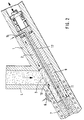
- Fig. 3
- ein Ausführungsbeispiel der Vorrichtung zur Durchführung des Verfahrens, bei welcher die Preßform vertikal angeordnet ist.
- Fig. 1
- an embodiment of the device for performing the method, in which the mold is arranged horizontally,
- Fig. 2
- an embodiment of the device for performing the method in which the mold is arranged obliquely and
- Fig. 3
- an embodiment of the device for performing the method in which the mold is arranged vertically.
Wie aus Fig. 1 zu erkennen ist, enthält die
Preßvorrichtung ein Rohr 1 größerer Länge,d.h. die Länge
des Rohres beträgt ein Vielfaches des Preßhubes . Im Rohr
1 ist längsverschiebbar der Preßkolben 2 angeordnet.
Seitlich im Rohr 1 ist die Füllöffnung 3 vorgesehen,
welche sich am Ende des Füllschachtes 4 befindet, durch
welche das zu pressende Gemisch in die Preßform im Inneren
des Rohres 1 befördert wird. In Preßrichtung gesehen
hinter der Füllöffnung sind in der Rohrwand
Zuführungskanäle 5 für die heißen Gase oder Dämpfe
vorgesehen, welche über die Sammelleitung 6 mit einem
(nicht gezeigten ) Reservoir verbunden sind. Außerdem ist
in der Rohrwandung eine Heizung 7 vorgesehen,beispielweise
eine elektrisch oder durch eine heiße Flüssigkeit
betriebene Heizung. Die Oberfläche des Preßkolbens ist
strukturiert, beispielweise mit einer Riffelung 8
versehen.As can be seen from Fig. 1, the
Press device a
Die Funktionswise der aus Fig.1 ersichtlichen
Preßvorrichtung ist wie folgt :Bei der in Fig. 1 gezeigten
Stellung des Preßkolbens kann das zu pressende Gemisch
durch den Füllschacht 4 und die Füllöffnung 3 in die
Preßform 9 gelangen. Wenn die Preßform 9 gefüllt ist, wird
der Preßkolben 2 veranlaßt, den ersten Preßhub
auszuführen, wodurch der Preßkolben bis an das Ende des
Pfeiles 10 verschoben wird. Dadurch ist das rechte Ende
der Preßform verschlossen worden. Nun wird dem geringfügig
komprimierten Gemisch durch aus den Zuführungskanälen 5
eingeleitete heiße Gase oder Dämpfe und durch die Heizung
7 eine solche Wärmemenge zugeführt, welche zur Aushärtung
des im Gemisch befindlichen Bindemittels benötigt wird. The mode of operation shown in Fig.1
Pressing device is as follows: In the one shown in Fig. 1
Position of the plunger can be the mixture to be pressed
through the
Danach wird der Preßkolben 2 veranlaßt, den zweiten
Preßhub auszuführen, wie durch den Pfeil 11 verdeutlicht.
Dabei wird das Gemisch auf seine endgültige Dichte
fertiggepreßt und härtet aus.Beim zweiten Preßhub hat der
Preßkolben 2 das schon in der Preßvorrichtung befindliche
Formteil 12 weitergeschoben. Die Riffelung 8 im Preßkolben
2 sorgt dafür, daß eine entsprechende Riffelung auch an
den Endflächen der gepreßten Formteile entsteht,
so daß sich diese leichter zu einem Strang verbinden.Then the
Die Innenkontur des Rohres 1 ist entsprechend dem
herzustellenden Formteil ausgebildet. Das Rohr 1 kann
beispielsweise einen kreisförmigen Querschnitt aufweisen.
Der Querschnitt kann aber auch quadratisch oder mehreckig
sein. Es ist auch möglich. daß sich der Querschnitt im
Preßbereich verringert , so daß beim zweiten Preßhub noch
ein zusätzlicher Preßdruck vom Umfang her erfolgt.The inner contour of the
Bei der in Fig. 2 gezeigten Ausführungsform der
Preßvorrichtung sind die Teile, die in ihrer Funktion mit
den Teilen der in Fig. 1 gezeigten Preßvorrichtung
identisch sind, mit den gleichen Bezugszeichen versehen.
Ein Unterschied zwischen den Preßvorrichtungen besteht
darin, daß das Rohr 1 gegenüber der Horizontalen schräg
angeordnet ist. Auf diese Weise kann das Einfüllen des
Gemischs in die Preßform 9 erleichtert werden. Außerdem
ist der Preßkolben 2 hohl ausgebildet und in ihm die
rohrförmige Verlängerung 13 angeordnet, deren hinteres
Ende mit einer Zuleitung 14 verbindbar ist, so daß nach
dem ersten Preßhub auch von innen heiße Gase oder Dämpfe
in das geringfügig verdichtete Gemisch eingeleitet werden
können. In the embodiment shown in FIG
Pressing device are the parts that work in their function
the parts of the pressing device shown in Fig. 1
are identical, provided with the same reference numerals.
There is a difference between the pressing devices
in that the
Die Preßvorrichtung gemäß Fig. 3 ist senkrecht angeordnet
und der Füllschacht 4 erstreckt sich parallel zum Rohr 1.
Zum Einbringen des Gemischs in die Preßform 9 ist ein in
einer im rechten Winkel zu Füllschacht 4 angeordnete
Führung 15 geführter Füllschieber 16 vorgesehen.3 is arranged vertically
and the
Claims (9)
dadurch gekennzeichnet, daß das in der Preßform ( 9 ) befindliche Gemisch durch wenigstens zwei Preßhübe in der Weise gepreßt wird, daß beim ersten Preßhub die Preßform ( 9 ) geschlossen wird, wobei das Gemisch gering verdichtet wird und das Gemisch beim zweiten Preßhub fertiggepreßt wird.A process for the production of molded parts from a non-flowable mixture of chip and / or fiber materials and thermosetting binders, in which the mixture is pressed and cured in a press with a mold closed on all sides and in which part of the heat energy required for curing is obtained during the Pressing is introduced into the mixture of hot gases or vapors which is introduced into the mixture in the compression mold in a direction which is essentially perpendicular to the pressing direction,
characterized in that the mixture in the press mold (9) is pressed by at least two press strokes in such a way that the press mold (9) is closed on the first press stroke, the mixture being slightly compressed and the mixture being pressed on the second press stroke.
dadurch gekennzeichnet, daß die heißen Gase oder Dämpfe nach dem ersten Preßhub in das Gemisch eingeführt werden und das Gemisch nach dem zweiten Preßhub zusätzlich von einer Heizeinrichtung (7) geheizt wird.Method according to claim 1,
characterized in that the hot gases or vapors are introduced into the mixture after the first press stroke and the mixture is additionally heated by a heating device (7) after the second press stroke.
dadurch gekennzeichnet, daß die Preßvorrichtung horizontal angeordnet ist.Device according to claim 3,
characterized in that the pressing device is arranged horizontally.
dadurch gekennzeichnet, daß die Preßvorrichtung schräg angeordnet ist.Device according to claim 3,
characterized in that the pressing device is arranged obliquely.
dadurch gekennzeichnet, daß die Preßvorrichtung senkrecht angeordnet ist.Device according to claim 3,
characterized in that the pressing device is arranged vertically.
gekennzeichnet durch folgende Merkmale :
characterized by the following features:
dadurch gekennzeichnet, daß die dem Verdichtungsbereich zugewandte Oberfläche des Preßkolbens mit einer Strukturierung ( 8 ) versehen ist.Device according to claims 3 and 7 and one of claims 4 to 6,
characterized in that the surface of the plunger facing the compression region is provided with a structure (8).
dadurch gekennzeichnet, daß die Fülleinrichtung aus einem parallel zur Preßform angeordneten Füllschacht ( 4 ) besteht, dessen unteres Ende zum Hubbereich hin offen ist und in dem ein zum Hubbreich hin horizontal verschiebbarer Füllschieber ( 16 ) vorgesehen ist.Device according to claims 3, 6, 7 and 8,
characterized in that the filling device consists of a filling shaft (4) arranged parallel to the press mold, the lower end of which is open towards the stroke area and in which a filling slide (16) which is horizontally displaceable towards the stroke area is provided.
Priority Applications (6)
| Application Number | Priority Date | Filing Date | Title |
|---|---|---|---|
| AT97117550T ATE268252T1 (en) | 1997-10-10 | 1997-10-10 | METHOD AND DEVICE FOR PRODUCING MOLDED PARTS |
| DE59711690T DE59711690D1 (en) | 1997-10-10 | 1997-10-10 | Method and device for producing molded parts |
| EP97117550A EP0908281B1 (en) | 1997-10-10 | 1997-10-10 | Method and apparatus for manufacturing moulded articles |
| ES97117550T ES2222492T3 (en) | 1997-10-10 | 1997-10-10 | PROCEDURE AND DEVICE FOR THE MANUFACTURE OF PREFORMED PARTS. |
| US09/139,911 US5972262A (en) | 1997-10-10 | 1998-08-26 | Method of and device for producing shaped parts |
| JP10287782A JPH11188749A (en) | 1997-10-10 | 1998-10-09 | Method and apparatus for producing molded product |
Applications Claiming Priority (1)
| Application Number | Priority Date | Filing Date | Title |
|---|---|---|---|
| EP97117550A EP0908281B1 (en) | 1997-10-10 | 1997-10-10 | Method and apparatus for manufacturing moulded articles |
Publications (2)
| Publication Number | Publication Date |
|---|---|
| EP0908281A1 true EP0908281A1 (en) | 1999-04-14 |
| EP0908281B1 EP0908281B1 (en) | 2004-06-02 |
Family
ID=8227463
Family Applications (1)
| Application Number | Title | Priority Date | Filing Date |
|---|---|---|---|
| EP97117550A Expired - Lifetime EP0908281B1 (en) | 1997-10-10 | 1997-10-10 | Method and apparatus for manufacturing moulded articles |
Country Status (6)
| Country | Link |
|---|---|
| US (1) | US5972262A (en) |
| EP (1) | EP0908281B1 (en) |
| JP (1) | JPH11188749A (en) |
| AT (1) | ATE268252T1 (en) |
| DE (1) | DE59711690D1 (en) |
| ES (1) | ES2222492T3 (en) |
Cited By (8)
| Publication number | Priority date | Publication date | Assignee | Title |
|---|---|---|---|---|
| WO2000040384A1 (en) * | 1998-12-30 | 2000-07-13 | Haller Formholz | Method and device for continuously producing shaped bodies |
| DE102004010461A1 (en) * | 2004-03-01 | 2005-09-29 | Oechsler Ag | Extrusion of plastic profiles containing natural fillers involves extrusion of a plastic and filler mixture through a die and cooling in a temperature gradient which solidifies the outer area then cools remaining bulk |
| EP1752268A2 (en) * | 2005-08-10 | 2007-02-14 | Karl Schedlbauer | Process and apparatus for obtaining a equal strand density and for curing strands from plant particles |
| EP1752267A2 (en) | 2005-08-10 | 2007-02-14 | Anton Heggenstaller GmbH | Method for the production of extruded products and extrusion press |
| EP1925413A3 (en) * | 2006-11-21 | 2009-04-01 | Anton Heggenstaller GmbH | Method and extrusion press for manufacturing extrusion press products |
| WO2009094011A1 (en) * | 2008-01-24 | 2009-07-30 | Agriboard Industries | Method for making a compressed fiberboard |
| CN103659987A (en) * | 2013-12-04 | 2014-03-26 | 盛威机械贸易有限公司 | Double-tower extrusion device and method for extruding wood chips by using double-tower extrusion device |
| US10414064B1 (en) | 2019-03-14 | 2019-09-17 | Agriboard International, Llc | Efficient method and apparatus for producing compressed structural fiberboard |
Families Citing this family (3)
| Publication number | Priority date | Publication date | Assignee | Title |
|---|---|---|---|---|
| US6561787B2 (en) | 1999-09-29 | 2003-05-13 | Kansas State University Research Foundation | Apparatus for forming biodegradable and edible feed packaging materials |
| ITMO20050348A1 (en) * | 2005-12-23 | 2007-06-24 | Imal Srl | SYSTEM FOR PRESSING WITH EXTRUSION OF INCOERENT WOODEN MATERIAL AND RELATIVE PRESSING METHOD |
| US9683186B2 (en) * | 2013-05-31 | 2017-06-20 | C-Power Tech, LLC | Carpet pellet machine |
Citations (5)
| Publication number | Priority date | Publication date | Assignee | Title |
|---|---|---|---|---|
| DE918977C (en) * | 1952-01-19 | 1954-10-07 | Buckau Wolf Maschf R | Extruder for peat, lignite or the like. |
| EP0339495A2 (en) * | 1988-04-26 | 1989-11-02 | Karl Schedlbauer | Method and device for profile extruding, especially tube extruding, a mixture of plant particles with binding agents |
| EP0376175A2 (en) * | 1988-12-29 | 1990-07-04 | Karl Schedlbauer | Method and device for controlling the compression and/or for producing a fringe with a higher density with a modified surface while extruding particles, particularly vegetable particles with binding agents |
| EP0443053A1 (en) * | 1990-02-20 | 1991-08-28 | Werzalit Ag + Co. | Method and device for the production of shaped parts |
| EP0573695A1 (en) * | 1992-06-10 | 1993-12-15 | Mikhail Vasilievich Birjukov | A method for molding shaped products and an apparatus for carrying out same |
Family Cites Families (5)
| Publication number | Priority date | Publication date | Assignee | Title |
|---|---|---|---|---|
| DE2932406C2 (en) * | 1979-08-09 | 1983-06-23 | Anton 8892 Kühbach Heggenstaller | Process and devices for extrusion of a mixture on small plant parts and binders |
| CN1009443B (en) * | 1986-11-14 | 1990-09-05 | 库特·赫尔德·法布里肯特 | Process and apparatus for producing composite wood sheet |
| DE3726921A1 (en) * | 1987-02-10 | 1988-08-18 | Menzolit Gmbh | SEMI-FINISHED PRODUCT AND METHOD AND DEVICE FOR PRODUCING MOLDED SEMI-PREPARED PRODUCTS FROM THERMOPLAST |
| ZA901076B (en) * | 1989-02-14 | 1990-11-28 | Csr Ltd | Improved production process and apparatus |
| US5413746A (en) * | 1992-06-10 | 1995-05-09 | Birjukov; Mikhail V. | Method for molding shaped products and an apparatus for carrying out same |
-
1997
- 1997-10-10 EP EP97117550A patent/EP0908281B1/en not_active Expired - Lifetime
- 1997-10-10 ES ES97117550T patent/ES2222492T3/en not_active Expired - Lifetime
- 1997-10-10 AT AT97117550T patent/ATE268252T1/en not_active IP Right Cessation
- 1997-10-10 DE DE59711690T patent/DE59711690D1/en not_active Expired - Fee Related
-
1998
- 1998-08-26 US US09/139,911 patent/US5972262A/en not_active Expired - Lifetime
- 1998-10-09 JP JP10287782A patent/JPH11188749A/en active Pending
Patent Citations (5)
| Publication number | Priority date | Publication date | Assignee | Title |
|---|---|---|---|---|
| DE918977C (en) * | 1952-01-19 | 1954-10-07 | Buckau Wolf Maschf R | Extruder for peat, lignite or the like. |
| EP0339495A2 (en) * | 1988-04-26 | 1989-11-02 | Karl Schedlbauer | Method and device for profile extruding, especially tube extruding, a mixture of plant particles with binding agents |
| EP0376175A2 (en) * | 1988-12-29 | 1990-07-04 | Karl Schedlbauer | Method and device for controlling the compression and/or for producing a fringe with a higher density with a modified surface while extruding particles, particularly vegetable particles with binding agents |
| EP0443053A1 (en) * | 1990-02-20 | 1991-08-28 | Werzalit Ag + Co. | Method and device for the production of shaped parts |
| EP0573695A1 (en) * | 1992-06-10 | 1993-12-15 | Mikhail Vasilievich Birjukov | A method for molding shaped products and an apparatus for carrying out same |
Cited By (16)
| Publication number | Priority date | Publication date | Assignee | Title |
|---|---|---|---|---|
| US6479002B1 (en) | 1998-12-30 | 2002-11-12 | Haller Formholz | Extrusion of plant materials encapsulated in a thermoplastic |
| WO2000040384A1 (en) * | 1998-12-30 | 2000-07-13 | Haller Formholz | Method and device for continuously producing shaped bodies |
| DE102004010461A1 (en) * | 2004-03-01 | 2005-09-29 | Oechsler Ag | Extrusion of plastic profiles containing natural fillers involves extrusion of a plastic and filler mixture through a die and cooling in a temperature gradient which solidifies the outer area then cools remaining bulk |
| EP1752268A2 (en) * | 2005-08-10 | 2007-02-14 | Karl Schedlbauer | Process and apparatus for obtaining a equal strand density and for curing strands from plant particles |
| EP1752267A2 (en) | 2005-08-10 | 2007-02-14 | Anton Heggenstaller GmbH | Method for the production of extruded products and extrusion press |
| EP1752267A3 (en) * | 2005-08-10 | 2008-02-13 | Anton Heggenstaller GmbH | Method for the production of extruded products and extrusion press |
| EP1752268A3 (en) * | 2005-08-10 | 2009-01-21 | Karl Schedlbauer | Process and apparatus for obtaining a equal strand density and for curing strands from plant particles |
| EP2425947A2 (en) | 2006-11-21 | 2012-03-07 | Anton Heggenstaller GmbH | Extrusion device |
| EP1925413A3 (en) * | 2006-11-21 | 2009-04-01 | Anton Heggenstaller GmbH | Method and extrusion press for manufacturing extrusion press products |
| EP2425947A3 (en) * | 2006-11-21 | 2012-11-14 | Anton Heggenstaller GmbH | Extrusion device |
| WO2009094011A1 (en) * | 2008-01-24 | 2009-07-30 | Agriboard Industries | Method for making a compressed fiberboard |
| US8052842B2 (en) | 2008-01-24 | 2011-11-08 | Agriboard Industries | Method for making a compressed structural fiberboard |
| CN103659987A (en) * | 2013-12-04 | 2014-03-26 | 盛威机械贸易有限公司 | Double-tower extrusion device and method for extruding wood chips by using double-tower extrusion device |
| CN103659987B (en) * | 2013-12-04 | 2015-08-12 | 盛威机械贸易有限公司 | Double-tower extrusion device and utilize double-tower extrusion device to extrude the method for wood chip |
| US10414064B1 (en) | 2019-03-14 | 2019-09-17 | Agriboard International, Llc | Efficient method and apparatus for producing compressed structural fiberboard |
| US11192274B2 (en) | 2019-03-14 | 2021-12-07 | Agriboard International, Llc | Efficient method and apparatus for producing compressed structural fiberboard |
Also Published As
| Publication number | Publication date |
|---|---|
| US5972262A (en) | 1999-10-26 |
| EP0908281B1 (en) | 2004-06-02 |
| ES2222492T3 (en) | 2005-02-01 |
| ATE268252T1 (en) | 2004-06-15 |
| DE59711690D1 (en) | 2004-07-08 |
| JPH11188749A (en) | 1999-07-13 |
Similar Documents
| Publication | Publication Date | Title |
|---|---|---|
| AT398934B (en) | METHOD AND DEVICE FOR PRODUCING BLOCKS FROM ANY MATERIAL AND BLOCKS AS AN IMMEDIATE PRODUCT OF THIS METHOD | |
| EP0149996A2 (en) | Method and machine for manufacturing brushes | |
| EP0908281B1 (en) | Method and apparatus for manufacturing moulded articles | |
| EP0376175B1 (en) | Method and device for controlling the compression and/or for producing a fringe with a higher density with a modified surface while extruding particles, particularly vegetable particles with binding agents | |
| DE3930840C2 (en) | ||
| EP1066138B1 (en) | Method and device for producing a profiled material | |
| DE3916774C2 (en) | ||
| DE102005051205A1 (en) | Making articles from thermoplastic polymer material comprises separately heating a monomer component and another component, mixing the components and pouring the mixture into a mold | |
| DE2710779C2 (en) | Injection device for injection molding of thermoplastics or rubber compounds | |
| CH387287A (en) | Method and device for automatic transfer molding of curable molding compounds | |
| DE557268C (en) | Method and device for the production of molded parts from synthetic resin | |
| DE2932405A1 (en) | Extruding wood chipboard - using intermittently acting ram thrusting charge into first consolidating passage entrance while closing off inlet | |
| DE2539674A1 (en) | Continuous sections of cellulosic material - produced with binder by pulsatingly forcing mass through narrower heated extrusion tool | |
| DE1247002B (en) | Method and device for extrusion of profiled products from a mixture of shredded chips of wood waste, agricultural waste products and similar raw material with polymer binders | |
| EP0638401B1 (en) | Method and device for profile extruding, especially tube extruding a mixture of plant particles with binding agents | |
| DE19840790A1 (en) | Method for feeding fragments to extruder for board or tubular materials | |
| EP0429516B1 (en) | Device and process for shaping semi-finished products from high molecular weight plastics | |
| DE3611688C2 (en) | ||
| DE3224800A1 (en) | Process and device for extruding a candle strand | |
| DE7007897U (en) | INJECTION MOLDING MACHINE. | |
| DE10245284A1 (en) | For the production of wood blocks, from an extruded strand of compressed and glued wood particles/chips, the wood material is heated on entering the filling/press zone of the extrusion press | |
| DE3008766C2 (en) | ||
| EP0718079B1 (en) | Process and device for the manufacture of tube panels and strips | |
| DE102006032149A1 (en) | Process for extruding plant material parts e.g. wood chips comprises unevenly pre-compressing the material in a pressing chamber to eliminate compression differences caused by an extrusion die and produce uniformly compressed extruded parts | |
| DE19803422A1 (en) | Method and device for the injection molding of fiber-reinforced plastics |
Legal Events
| Date | Code | Title | Description |
|---|---|---|---|
| PUAI | Public reference made under article 153(3) epc to a published international application that has entered the european phase |
Free format text: ORIGINAL CODE: 0009012 |
|
| AK | Designated contracting states |
Kind code of ref document: A1 Designated state(s): AT BE CH DE DK ES FI FR GB IE IT LI NL PT SE |
|
| 17P | Request for examination filed |
Effective date: 19990604 |
|
| AKX | Designation fees paid |
Free format text: AT BE CH DE DK ES FI FR GB IE IT LI NL PT SE |
|
| 17Q | First examination report despatched |
Effective date: 20021202 |
|
| GRAP | Despatch of communication of intention to grant a patent |
Free format text: ORIGINAL CODE: EPIDOSNIGR1 |
|
| GRAS | Grant fee paid |
Free format text: ORIGINAL CODE: EPIDOSNIGR3 |
|
| GRAA | (expected) grant |
Free format text: ORIGINAL CODE: 0009210 |
|
| AK | Designated contracting states |
Kind code of ref document: B1 Designated state(s): AT BE CH DE DK ES FI FR GB IE IT LI NL PT SE |
|
| PG25 | Lapsed in a contracting state [announced via postgrant information from national office to epo] |
Ref country code: FI Free format text: LAPSE BECAUSE OF FAILURE TO SUBMIT A TRANSLATION OF THE DESCRIPTION OR TO PAY THE FEE WITHIN THE PRESCRIBED TIME-LIMIT Effective date: 20040602 |
|
| REG | Reference to a national code |
Ref country code: GB Ref legal event code: FG4D Free format text: NOT ENGLISH |
|
| REG | Reference to a national code |
Ref country code: CH Ref legal event code: EP |
|
| REF | Corresponds to: |
Ref document number: 59711690 Country of ref document: DE Date of ref document: 20040708 Kind code of ref document: P |
|
| REG | Reference to a national code |
Ref country code: IE Ref legal event code: FG4D Free format text: GERMAN |
|
| PG25 | Lapsed in a contracting state [announced via postgrant information from national office to epo] |
Ref country code: SE Free format text: LAPSE BECAUSE OF FAILURE TO SUBMIT A TRANSLATION OF THE DESCRIPTION OR TO PAY THE FEE WITHIN THE PRESCRIBED TIME-LIMIT Effective date: 20040902 Ref country code: DK Free format text: LAPSE BECAUSE OF FAILURE TO SUBMIT A TRANSLATION OF THE DESCRIPTION OR TO PAY THE FEE WITHIN THE PRESCRIBED TIME-LIMIT Effective date: 20040902 |
|
| GBT | Gb: translation of ep patent filed (gb section 77(6)(a)/1977) |
Effective date: 20040909 |
|
| REG | Reference to a national code |
Ref country code: CH Ref legal event code: NV Representative=s name: A. BRAUN, BRAUN, HERITIER, ESCHMANN AG PATENTANWAE |
|
| PG25 | Lapsed in a contracting state [announced via postgrant information from national office to epo] |
Ref country code: BE Free format text: LAPSE BECAUSE OF NON-PAYMENT OF DUE FEES Effective date: 20041031 |
|
| REG | Reference to a national code |
Ref country code: ES Ref legal event code: FG2A Ref document number: 2222492 Country of ref document: ES Kind code of ref document: T3 |
|
| ET | Fr: translation filed | ||
| PLBE | No opposition filed within time limit |
Free format text: ORIGINAL CODE: 0009261 |
|
| STAA | Information on the status of an ep patent application or granted ep patent |
Free format text: STATUS: NO OPPOSITION FILED WITHIN TIME LIMIT |
|
| BERE | Be: lapsed |
Owner name: WERZALIT A.G. + CO. Effective date: 20041031 |
|
| 26N | No opposition filed |
Effective date: 20050303 |
|
| BERE | Be: lapsed |
Owner name: *WERZALIT A.G. + CO. Effective date: 20041031 |
|
| PG25 | Lapsed in a contracting state [announced via postgrant information from national office to epo] |
Ref country code: PT Free format text: LAPSE BECAUSE OF NON-PAYMENT OF DUE FEES Effective date: 20041102 |
|
| REG | Reference to a national code |
Ref country code: CH Ref legal event code: PFA Owner name: WERZALIT AG + CO. Free format text: WERZALIT AG + CO.#GRONAUER STRASSE 70#D-71720 OBERSTENFELD (DE) -TRANSFER TO- WERZALIT AG + CO.#GRONAUER STRASSE 70#D-71720 OBERSTENFELD (DE) |
|
| PGFP | Annual fee paid to national office [announced via postgrant information from national office to epo] |
Ref country code: NL Payment date: 20081023 Year of fee payment: 12 |
|
| PGFP | Annual fee paid to national office [announced via postgrant information from national office to epo] |
Ref country code: IE Payment date: 20081028 Year of fee payment: 12 Ref country code: DE Payment date: 20081028 Year of fee payment: 12 Ref country code: CH Payment date: 20081027 Year of fee payment: 12 |
|
| PGFP | Annual fee paid to national office [announced via postgrant information from national office to epo] |
Ref country code: ES Payment date: 20081027 Year of fee payment: 12 Ref country code: AT Payment date: 20081023 Year of fee payment: 12 |
|
| PGFP | Annual fee paid to national office [announced via postgrant information from national office to epo] |
Ref country code: IT Payment date: 20081028 Year of fee payment: 12 |
|
| PGFP | Annual fee paid to national office [announced via postgrant information from national office to epo] |
Ref country code: FR Payment date: 20081021 Year of fee payment: 12 |
|
| PGFP | Annual fee paid to national office [announced via postgrant information from national office to epo] |
Ref country code: GB Payment date: 20081024 Year of fee payment: 12 |
|
| REG | Reference to a national code |
Ref country code: NL Ref legal event code: V1 Effective date: 20100501 |
|
| REG | Reference to a national code |
Ref country code: CH Ref legal event code: PL |
|
| REG | Reference to a national code |
Ref country code: IE Ref legal event code: MM4A |
|
| REG | Reference to a national code |
Ref country code: FR Ref legal event code: ST Effective date: 20100630 |
|
| PG25 | Lapsed in a contracting state [announced via postgrant information from national office to epo] |
Ref country code: NL Free format text: LAPSE BECAUSE OF NON-PAYMENT OF DUE FEES Effective date: 20100501 Ref country code: FR Free format text: LAPSE BECAUSE OF NON-PAYMENT OF DUE FEES Effective date: 20091102 Ref country code: DE Free format text: LAPSE BECAUSE OF NON-PAYMENT OF DUE FEES Effective date: 20100501 |
|
| PG25 | Lapsed in a contracting state [announced via postgrant information from national office to epo] |
Ref country code: AT Free format text: LAPSE BECAUSE OF NON-PAYMENT OF DUE FEES Effective date: 20091010 |
|
| PG25 | Lapsed in a contracting state [announced via postgrant information from national office to epo] |
Ref country code: LI Free format text: LAPSE BECAUSE OF NON-PAYMENT OF DUE FEES Effective date: 20091031 Ref country code: IE Free format text: LAPSE BECAUSE OF NON-PAYMENT OF DUE FEES Effective date: 20091012 Ref country code: CH Free format text: LAPSE BECAUSE OF NON-PAYMENT OF DUE FEES Effective date: 20091031 |
|
| PG25 | Lapsed in a contracting state [announced via postgrant information from national office to epo] |
Ref country code: GB Free format text: LAPSE BECAUSE OF NON-PAYMENT OF DUE FEES Effective date: 20091010 |
|
| REG | Reference to a national code |
Ref country code: ES Ref legal event code: FD2A Effective date: 20110309 |
|
| PG25 | Lapsed in a contracting state [announced via postgrant information from national office to epo] |
Ref country code: IT Free format text: LAPSE BECAUSE OF NON-PAYMENT OF DUE FEES Effective date: 20091010 |
|
| PG25 | Lapsed in a contracting state [announced via postgrant information from national office to epo] |
Ref country code: ES Free format text: LAPSE BECAUSE OF NON-PAYMENT OF DUE FEES Effective date: 20110308 |
|
| PG25 | Lapsed in a contracting state [announced via postgrant information from national office to epo] |
Ref country code: ES Free format text: LAPSE BECAUSE OF NON-PAYMENT OF DUE FEES Effective date: 20091011 |