EP0908217A1 - Verfahren for treating flue gas - Google Patents
Verfahren for treating flue gas Download PDFInfo
- Publication number
- EP0908217A1 EP0908217A1 EP98117313A EP98117313A EP0908217A1 EP 0908217 A1 EP0908217 A1 EP 0908217A1 EP 98117313 A EP98117313 A EP 98117313A EP 98117313 A EP98117313 A EP 98117313A EP 0908217 A1 EP0908217 A1 EP 0908217A1
- Authority
- EP
- European Patent Office
- Prior art keywords
- flue gas
- liquid
- water
- combustion chamber
- combustion
- Prior art date
- Legal status (The legal status is an assumption and is not a legal conclusion. Google has not performed a legal analysis and makes no representation as to the accuracy of the status listed.)
- Ceased
Links
Images
Classifications
-
- F—MECHANICAL ENGINEERING; LIGHTING; HEATING; WEAPONS; BLASTING
- F23—COMBUSTION APPARATUS; COMBUSTION PROCESSES
- F23J—REMOVAL OR TREATMENT OF COMBUSTION PRODUCTS OR COMBUSTION RESIDUES; FLUES
- F23J15/00—Arrangements of devices for treating smoke or fumes
- F23J15/003—Arrangements of devices for treating smoke or fumes for supplying chemicals to fumes, e.g. using injection devices
-
- B—PERFORMING OPERATIONS; TRANSPORTING
- B01—PHYSICAL OR CHEMICAL PROCESSES OR APPARATUS IN GENERAL
- B01D—SEPARATION
- B01D51/00—Auxiliary pretreatment of gases or vapours to be cleaned
- B01D51/02—Amassing the particles, e.g. by flocculation
- B01D51/04—Amassing the particles, e.g. by flocculation by seeding, e.g. by adding particles
-
- B—PERFORMING OPERATIONS; TRANSPORTING
- B01—PHYSICAL OR CHEMICAL PROCESSES OR APPARATUS IN GENERAL
- B01D—SEPARATION
- B01D53/00—Separation of gases or vapours; Recovering vapours of volatile solvents from gases; Chemical or biological purification of waste gases, e.g. engine exhaust gases, smoke, fumes, flue gases, aerosols
- B01D53/002—Separation of gases or vapours; Recovering vapours of volatile solvents from gases; Chemical or biological purification of waste gases, e.g. engine exhaust gases, smoke, fumes, flue gases, aerosols by condensation
-
- F—MECHANICAL ENGINEERING; LIGHTING; HEATING; WEAPONS; BLASTING
- F23—COMBUSTION APPARATUS; COMBUSTION PROCESSES
- F23G—CREMATION FURNACES; CONSUMING WASTE PRODUCTS BY COMBUSTION
- F23G2207/00—Control
- F23G2207/60—Additives supply
Definitions
- the invention relates to a method for the treatment of Flue gas from an incinerator with the characteristics of The preamble of claim 1.
- the heat transfer coefficient decreases heating surfaces; a Deterioration in heat transfer is observed.
- Flue gases temperature difference between the entry of the Flue gases in the boiler and the outlet of the flue gases from the Boiler. The result is a lower generated Amount of steam or the otherwise dissipated heat.
- the one Pollution caused reduced temperature reduction causes a reduced decoupling of energy.
- Operating states of the furnace can be a special type of Contamination of the solid walls of the flue gas Determine system parts.
- This pollution is in some Plants already found in the area of the heating surfaces, in In other plants, this pollution occurs in the area of Precipitation electrodes of an electrical dust collector to which Surfaces of any existing heat exchangers or on the walls of the Flue gas channels.
- This particular type of pollution consists of Deposits of solid substances, mostly inorganic salts, in the Airborne dust is involved. These deposits have one loose, crystalline structure of low strength.
- the invention has for its object the generic To design procedures so that the formation of the To prevent heat transfer reducing deposits or at least to decrease.
- the deposits Due to the morphological structure (loose, light Microstructure) the deposits have a heat insulation Effect. In addition, absorption or reflection occurs Heat radiation on what in the sum effect to one deteriorated heat transfer behavior of the heating surfaces leads. On other solid walls, for example in the area of Precipitation electrodes from electrical dust extractors or on Canal walls can deposit the deposits on others Impairment of the function of these components lead to, for example deterioration of dust separation or an increase of flow pressure losses.
- this Deposits occur due to the sublimation of substances had to, which at high temperatures the flue gases initially are in gaseous form, and at low temperatures approximately after Cooling near heating surfaces as solids desublimate.
- the substances separated by desublimation are either previously formed by chemical reaction or by sublimation of solid substances, which may be in the eliminating waste stream are present or in the Rostaschestrom are contained, converted into the gas phase.
- the chemical The composition of the heating surface coverings depends on the entry of the Substances in the gas phase by sublimation from the Solids located in the furnace rather than that close likely mechanism.
- the formation of solid Soiling of heating surfaces or other solid walls components carrying flue gas by desublimation of prevents the build-up of flue gas constituents or diminishes desublimation in places other than is specifically brought about these solid walls mentioned.
- a local cooling of the flue gases in Spaces brought about that are not in the immediate vicinity are surrounded by solid walls.
- This local cooling will by introducing an evaporable medium, e.g. water-containing liquids, preferably water.
- the vaporizable medium takes a part after the introduction the enthalpy of the flue gas, which is local cools down. The medium itself evaporates during this process.
- the flue gas can reduce the temperatures of the flue gas below the sublimation temperature of the deposit-forming substances to be brought.
- desublimation germs are in the medium to be evaporated suspended, or they are considered soluble substances in the too evaporating medium dissolved. The added substances become after released from the evaporation of the medium or crystallize.
- Rapid evaporation of the medium is very fine Crystals to be expected to have good properties as Possess desublimation germs.
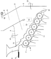
- the invention is based on exemplary embodiments and Drawing explains a waste incineration plant shows.
- the incinerator contains a combustion grate 1 and an overlying combustion chamber 2.
- the combustion chamber 2 is limited by the combustion grate 1, side walls, one Rear wall 3 and a firebox ceiling 4.
- a waste heat boiler 6 is connected via an afterburning zone 5, of which only the first tank train is shown.
- the combustion grate 1 is in the illustrated Incinerator formed from several grate rollers 7, the are arranged one behind the other along an inclined plane. Instead of a roller grate, a sliding grate can also be provided become.
- the waste to be incinerated is sent to a Feed hopper 8 and a push conveyor 9 abandoned and forms a bed 10 on the combustion grate 1. This bed 10 is by rotating the grate rollers 7 over the Combustion grate 1 promoted to a dropping 15.
- lances 12 are arranged in the firebox ceiling 4 and / or the rear wall 3 of the firebox 2 lances 12 are arranged. Additional lances 12 can be found in the Side walls at the installation locations marked with 13 be installed. Through the lances 12 an evaporating, Liquid containing additives, preferably water blown in. Each lance 12 is with one or more Atomizer nozzles provided the liquid to be injected is fed. The atomizer nozzles can also use steam or compressed air as an atomizing medium. It is favorable to install the lances 12 in a position that the Close the lance openings flush with the combustion chamber walls.
- the liquid is blown into the part of the combustion chamber 2, in which flue gas temperatures exceed 950 to 1050 ° C are expected.
- the lances 12 are under one appropriate angle directed into the combustion chamber 2.
- the jet pulse introduced by the lances 12 Liquid jets through the design of the atomizer nozzles and if necessary by the choice of the pressure of the Adjust the atomizing medium accordingly.
- the drop spectrum of the atomized liquid can be relatively coarse since the liquid drops are far in should reach the firebox 2. To achieve this Degree of atomization is an opening angle of the Liquid jet set from 10 to 60 degrees.
- the Atomization of the liquid can make atomizer nozzles known Type can be used.
- the atomizer nozzles are one heat-resistant ceramic material, e.g. B. silicon carbide manufactured and therefore also withstand higher heat effects by radiation from the combustion chamber 2.
- To avoid Incrustations at the mouth of the nozzles or lances 12 can the use of an air curtain to shield the Lance mouth from the hot smoke gases from the interior of the combustion chamber be beneficial.
- the atomizing air and the fog air can be the secondary air intended for the incineration of waste replace partially or completely.
- the liquid evaporates in the hot zone of the firebox 2 Completely.
- the additives contained in the liquid are released after evaporation of the liquid or crystallize and form very fine seeds.
- the in Flue gas existing, sublimed, deposit-forming substances attach themselves to these germs and are therefore harmless made.
- These substances bind the existing in the flue gas Hydrogen chloride.
- clay minerals such as kaolin, Kaolinite, montmorillonite, bentonite, vermiculite, mica, Pyrophillite, or mixtures thereof can be used. This Minerals bind the deposit-forming substances sublimed in the flue gas Fabrics.
- the additives can already be in the liquid be included. This applies to process water, which in a Plant for the desulphurization of exhaust gases Waste incineration plants comes and that in an advantageous manner can be used. This process water is with lime added and contains reaction products, eg. B. gypsum from the Exhaust gas desulphurization process.
- the dosage of the liquid containing the additive is too reduce or refrain if the temperature of the Flue gas in the combustion chamber 2 is so low that a complete burnout of the garbage should not be ensured.
- This z. B the case when the temperature of the flue gas after the last addition of the combustion air the value of 850 ° C falls below. In this case, the dosage of the additives containing liquid is not necessary because of the formation of the deposit-forming substances or their transfer into the Gas phase does not occur at these temperatures.
- a The temperature of the flue gas is monitored by a Sensor 14, the outlet of the flue gas from the combustion chamber 2 or is arranged in the first tank train.
- the Temperature monitoring can also be done through a thermography system, especially through an imaging thermography system take place, which in one of the firebox walls or the Firebox ceiling 4 can be accommodated.
Landscapes
- Chemical & Material Sciences (AREA)
- Chemical Kinetics & Catalysis (AREA)
- Engineering & Computer Science (AREA)
- General Chemical & Material Sciences (AREA)
- Mechanical Engineering (AREA)
- General Engineering & Computer Science (AREA)
- Analytical Chemistry (AREA)
- Oil, Petroleum & Natural Gas (AREA)
- Treating Waste Gases (AREA)
Abstract
Description
Die Erfindung betrifft ein verfahren zur Behandlung von Rauchgas aus einer Verbrennungsanlage mit den Merkmalen des Oberbegriffes des Anspruches 1.The invention relates to a method for the treatment of Flue gas from an incinerator with the characteristics of The preamble of claim 1.
Die dem Wärmeentzug dienenden Heizflächen des Abhitzekessels verschmutzen im Laufe der Betriebszeit. Durch Verschmutzung der Heizflächen nimmt der Wärmeübergangskoeffizient ab; eine Verschlechterung des Wärmeübergangs wird beobachtet. Bei als konstant angenommener Temperatur der Rauchgase bei Eintritt in den Kessel nimmt dabei die im Kessel erreichbare Abkühlung der Rauchgase (Temperaturdifferenz zwischen dem Eintritt der Rauchgase in den Kessel und dem Austritt der Rauchgase aus dem Kessel) ab. In der Folge resultiert eine geringere erzeugte Dampfmenge oder der sonst abgeführten Wärme. Der durch eine Verschmutzung auftretende verminderte Temperaturabbau bewirkt eine verminderte Auskopplung von Energie.The heating surfaces of the waste heat boiler used to extract heat pollute in the course of the operating time. By polluting the The heat transfer coefficient decreases heating surfaces; a Deterioration in heat transfer is observed. At as constant assumed temperature of the flue gases when entering the boiler takes the cooling that can be achieved in the boiler Flue gases (temperature difference between the entry of the Flue gases in the boiler and the outlet of the flue gases from the Boiler). The result is a lower generated Amount of steam or the otherwise dissipated heat. The one Pollution caused reduced temperature reduction causes a reduced decoupling of energy.
In ungünstigen, nicht vermiedenen oder vermeidbaren Betriebszuständen der Feuerung läßt sich eine besondere Art der Verschmutzung der festen Wände der das Rauchgas führenden Anlagenteile feststellen. Diese Verschmutzung wird in einigen Anlagen bereits im Bereich der Heizflächen festgestellt, in anderen Anlagen treten diese Verschmutzungen im Bereich der Niederschlagselektroden eines Elektroentstaubers, an den Oberflächen ggf. vorhandener Wärmetauscher oder auf Wänden der Rauchgaskanäle auf.In unfavorable, unavoidable or avoidable Operating states of the furnace can be a special type of Contamination of the solid walls of the flue gas Determine system parts. This pollution is in some Plants already found in the area of the heating surfaces, in In other plants, this pollution occurs in the area of Precipitation electrodes of an electrical dust collector to which Surfaces of any existing heat exchangers or on the walls of the Flue gas channels.
Diese genannte besondere Art der Verschmutzung besteht aus Ablagerungen fester Stoffe, meist anorganischer Salze, in die Flugstaub eingebunden ist. Diese Ablagerungen besitzen eine lockere, kristalline Struktur geringer Festigkeit. This particular type of pollution consists of Deposits of solid substances, mostly inorganic salts, in the Airborne dust is involved. These deposits have one loose, crystalline structure of low strength.
Der Erfindung liegt die Aufgabe zugrunde, das gattungsgemäße Verfahren so zu gestalten, daß die Bildung von den Wärmeübergang vermindernden Ablagerungen zu verhindern oder zumindest zu verringern.The invention has for its object the generic To design procedures so that the formation of the To prevent heat transfer reducing deposits or at least to decrease.
Aufgrund der morphologischen Struktur (lockeres, leichtes Gefüge) besitzen die Ablagerungen eine wärmeisolierende Wirkung. Zusätzlich tritt eine Absorption oder Reflexion der Wärmestrahlung auf, was in der Summenwirkung zu einem verschlechtertem Wärmeübertragungsverhalten der Heizflächen führt. Auf anderen festen Wänden, etwa im Bereich der Niederschlagselektroden von Elektroentstaubern oder auf Kanalwandungen können die Ablagerungen zu anderen Beeinträchtigungen der Funktion dieser Bauteile führen, etwa zu einer verschlechterten Staubabscheidung oder zu einer Erhöhung von Strömungsdruckverlusten.Due to the morphological structure (loose, light Microstructure) the deposits have a heat insulation Effect. In addition, absorption or reflection occurs Heat radiation on what in the sum effect to one deteriorated heat transfer behavior of the heating surfaces leads. On other solid walls, for example in the area of Precipitation electrodes from electrical dust extractors or on Canal walls can deposit the deposits on others Impairment of the function of these components lead to, for example deterioration of dust separation or an increase of flow pressure losses.
Diese Aufgabe wird bei einem gattungsgemäßen Verfahren erfindungsgemäß durch die kennzeichnenden Merkmale des Anspruches 1 gelöst. Vorteilhafte Ausgestaltungen der Erfindung sind Gegenstand der Unteransprüche.This task is carried out in a generic method according to the invention by the characterizing features of Claim 1 solved. Advantageous embodiments of the invention are the subject of the subclaims.
Durch eine kristallographische, morphologische und chemische Begutachtung der Ablagerungen ließ sich folgern, daß diese Ablagerungen durch Desublimation von Substanzen auftreten mußten, die bei hohen Temperaturen der Rauchgase zunächst gasförmig vorliegen, und bei niederen Temperaturen etwa nach Abkühlung in der Nähe von Heizflächen als Feststoffe desublimieren. Die durch Desublimation abgeschiedenen Stoffe werden zuvor entweder durch chemische Reaktion gebildet oder durch Sublimation fester Stoffe, die ggf. in dem zu beseitigenden Müllstrom vorhanden sind bzw. im Rostaschestrom enthalten sind, in die Gasphase überführt. Die chemische Zusammensetzung der Heizflächenbeläge läßt auf den Eintrag der Substanzen in die Gasphase durch Sublimation aus den im Feuerraum befindlichen Feststoffen als den eher wahrscheinlichen Mechanismus schließen. Durch einen Vergleich von Betriebsparametern verschiedener Feuerungen und die Bewertung der Wärmeübergänge im Kessel wurde der Schluß gezogen, daß insbesondere hohe Feuerraumtemperaturen die Minderung der Wärmeübergangskoeffizienten begünstigen können.Through a crystallographic, morphological and chemical Assessment of the deposits could be concluded that this Deposits occur due to the sublimation of substances had to, which at high temperatures the flue gases initially are in gaseous form, and at low temperatures approximately after Cooling near heating surfaces as solids desublimate. The substances separated by desublimation are either previously formed by chemical reaction or by sublimation of solid substances, which may be in the eliminating waste stream are present or in the Rostaschestrom are contained, converted into the gas phase. The chemical The composition of the heating surface coverings depends on the entry of the Substances in the gas phase by sublimation from the Solids located in the furnace rather than that close likely mechanism. By comparison of operating parameters of various furnaces and the The conclusion was the evaluation of the heat transfer in the boiler drawn that in particular high furnace temperatures the Reduction of the heat transfer coefficient can favor.
Durch die Erfindung wird nun die Bildung von festen Verschmutzungen von Heizflächen oder von anderen festen Wänden rauchgasführender Bauteile durch Desublimation von belagbildenden Rauchgasinhaltsstoffen dadurch verhindert oder vermindert, daß die Desublimation an anderen Orten als an diesen genannten festen Wänden gezielt herbeigeführt wird. Zu diesem Zweck wird eine örtliche Abkühlung der Rauchgase in Raumbereichen herbeigeführt, die nicht in unmittelbarer Nähe von festen Wänden umgeben sind. Diese lokale Abkühlung wird durch Einbringung eines verdampfbaren Mediums, z.B. wasserhaltiger Flüssigkeiten, vorzugsweise Wasser, erreicht. Das verdampfbare Medium nimmt nach der Einbringung einen Teil der Enthalpie des Rauchgases auf, wobei sich dieses lokal abkühlt. Das Medium selbst verdampft bei diesem Vorgang. In unmittelbarer Nähe des verdampfenden Mediums stellt sich dabei eine Temperatur nahe der Siedetemperatur des Mediums ein, im Falle wäßriger Flüssigkeiten etwa 100 °C - 110°C. Bei der Abkühlung des Rauchgases können die Temperaturen des Rauchgases unter die Sublimationstemperatur der belagbildenden Substanzen gebracht werden.Through the invention, the formation of solid Soiling of heating surfaces or other solid walls components carrying flue gas by desublimation of prevents the build-up of flue gas constituents or diminishes desublimation in places other than is specifically brought about these solid walls mentioned. To For this purpose, a local cooling of the flue gases in Spaces brought about that are not in the immediate vicinity are surrounded by solid walls. This local cooling will by introducing an evaporable medium, e.g. water-containing liquids, preferably water. The vaporizable medium takes a part after the introduction the enthalpy of the flue gas, which is local cools down. The medium itself evaporates during this process. In the immediate vicinity of the evaporating medium arises a temperature close to the boiling point of the medium For aqueous liquids about 100 ° C - 110 ° C. In the Cooling the flue gas can reduce the temperatures of the flue gas below the sublimation temperature of the deposit-forming substances to be brought.
Zur Erreichung einer Desublimation ist neben der Unterschreitung einer Gleichgewichtstemperatur noch die Anwesenheit von Kristallisations- oder Desublimationskeimen erforderlich. Es ist vorteilhaft, zusätzliche Desublimationskeime in die Rauchgaswege einzubringen. Diese Desublimationskeime werden in dem zu verdampfenden Medium suspendiert, oder sie werden als lösliche Substanzen in dem zu verdampfenden Medium gelöst. Die zugesetzten Stoffe werden nach der Verdampfung des Mediums freigesetzt oder kristallisieren. To achieve desublimation is next to the Falling below an equilibrium temperature still the Presence of crystallization or desublimation seeds required. It is beneficial to have additional ones Introduce desublimation germs into the flue gas passages. This Desublimation germs are in the medium to be evaporated suspended, or they are considered soluble substances in the too evaporating medium dissolved. The added substances become after released from the evaporation of the medium or crystallize.
Bei einer raschen Verdampfung des Mediums sind sehr feine Kristalle zu erwarten, die gute Eigenschaften als Desublimationskeime besitzen.Rapid evaporation of the medium is very fine Crystals to be expected to have good properties as Possess desublimation germs.
Es kann von Vorteil sein, wenn als nach der Verdampfung keimbildende Substanzen Stoffe eingesetzt werden, die in der Lage sind, mit im Rauchgas befindlichen Schadstoffen chemische Reaktionen einzugehen. Vorteilhaft ist die Einbringung einer Kalkmilchlösung, die beispielsweise mit Chlorwasserstoff eine Neutralisationsreaktion zeigt. Diese Reaktion führt zu einer Absenkung der Chlorwasserstoffkonzentration. Aus der chemischen Analyse der Verschmutzungen kann auf eine Beteiligung des Chlorwasserstoffs an der Bildung der den Wärmeübergang mindernden Ablagerungen geschlossen werden. Eine Reduktion der Chlorwasserstoffkonzentration kann auch durch andere Neutralisationsmittel herbeigeführt werden, insbesondere durch Hydroxide, Oxide, Carbonate oder Hydrogencarbonate von Alkali- und/oder Erdalkalimetallen.It can be beneficial if as after evaporation nucleating substances are used in the Are able to chemical with pollutants in the flue gas To respond. The introduction of one is advantageous Lime milk solution, for example with a hydrogen chloride Neutralization reaction shows. This reaction leads to one Lowering the concentration of hydrogen chloride. From the chemical Analysis of the pollution can be based on a participation of the Hydrogen chloride at the formation of the heat transfer reducing deposits can be closed. A reduction in Hydrogen chloride concentration can also be caused by others Neutralizing agents are brought about, in particular by Hydroxides, oxides, carbonates or hydrogen carbonates of alkali and / or Alkaline earth metals.
Die Erfindung sei an Hand von Ausführungsbeispielen und der Zeichnung erläutert, die eine Anlage zur Verbrennung von Abfall zeigt.The invention is based on exemplary embodiments and Drawing explains a waste incineration plant shows.
Die Verbrennungsanlage enthält einen Verbrennungsrost 1 und
einen darüber liegenden Feuerraum 2. Der Feuerraum 2 ist
begrenzt durch den Verbrennungsrost 1, Seitenwände, eine
Rückwand 3 und eine Feuerraumdecke 4. An den Feuerraum 2
schließt sich über eine Nachbrennzone 5 ein Abhitzekessel 6 an,
von dem nur der erste Kesselzug gezeigt ist.The incinerator contains a combustion grate 1 and
an
Der Verbrennungsrost 1 ist bei der dargestellten
Verbrennungsanlage aus mehreren Rostwalzen 7 gebildet, die
entlang einer schrägen Ebene hintereinander angeordnet sind.
Anstelle eines Walzenrostes kann auch ein Schubrost vorgesehen
werden. Der zu verbrennende Abfall wird über einen
Aufgabetrichter 8 und einen Schubförderer 9 aufgegeben und
bildet auf dem Verbrennungsrost 1 ein Bett 10. Dieses Bett 10
wird durch eine Rotation der Rostwalzen 7 über den
Verbrennungsrost 1 zu einem Abwurf 15 gefördert.The combustion grate 1 is in the illustrated
Incinerator formed from
Ein Teil der zur Verbrennung des Abfalls erforderlichen
Verbrennungsluft wird durch Unterwindkanäle 11 unterhalb des
Verbrennungsrostes 1 zugeführt und tritt durch den
Verbrennungsrost 1 in das Bett 10 ein. Die restliche
Verbrennungsluft wird als Sekundärluft den Feuerraum 2 und/oder
in die sich an den Feuerraum 2 anschließende Nachbrennzone 5
eingeblasen.Part of the necessary to incinerate the waste
Combustion air is through the
In der Feuerraumdecke 4 und/oder der Rückwand 3 des Feuerraumes
2 sind Lanzen 12 angeordnet. Weitere Lanzen 12 können in den
Seitenwänden an den mit 13 gekennzeichneten Einbauorte
eingebaut sein. Durch die Lanzen 12 wird eine verdampfende,
Additive enthaltende Flüssigkeit, vorzugsweise Wasser
eingeblasen. Jede Lanze 12 ist mit einer oder mehreren
Zerstäuberdüsen versehen, der die einzublasende Flüssigkeit
zugeführt wird. Die Zerstäuberdüsen können zusätzlich mit Dampf
oder Druckluft als Zerstäubermedium beaufschlagt werden.
Günstig ist ein Einbau der Lanzen 12 in einer Position, daß die
Lanzenmündungen plan mit den Feuerraumwänden abschließen.In the firebox ceiling 4 and / or the
Die Flüssigkeit wird in den Teil des Feuerraumes 2 eingeblasen,
in dem Rauchgastemperaturen von mehr als 950 bis 1050 °C zu
erwarten sind. Zu diesem Zweck sind die Lanzen 12 unter einen
entsprechenden Winkel in den Feuerraum 2 gerichtet. Außerdem
ist der Strahlimpuls der durch die Lanzen 12 eingebrachten
Flüssigkeitsstrahlen durch die Gestaltung der Zerstäuberdüsen
und gegebenenfalls durch die Wahl des Druckes des
Zerstäubermediums entsprechend anzupassen. Dabei ist ein
Auftreffen der Flüssigkeit auf die Ausmauerung des Feuerraumes
2 oder auf andere feste Wände zu vermeiden, da Wärmespannungen
auftreten können, die zu Schädigungen führen. The liquid is blown into the part of the
Das Tropfenspektrum der zerstäubten Flüssigkeit kann
verhältnismäßig grob sein, da die Flüssigkeitstropfen weit in
den Feuerraum 2 gelangen sollen. Zur Erreichung dieses
Zerstäubungsgrades wird ein Öffnungswinkel des
Flüssigkeitsstrahles von 10 bis 60 Grad eingestellt. Für die
Zerstäubung der Flüssigkeit können Zerstäuberdüsen bekannter
Bauart verwendet werden. Die Zerstäuberdüsen sind aus einem
warmfesten keramischen Werkstoff, z. B. Silicium-Carbid
gefertigt und halten dadurch auch höheren Wärmeeinwirkungen
durch Strahlung aus dem Feuerraum 2 stand. Zur Vermeidung von
Inkrustierungen an der Mündung der Düsen bzw. Lanzen 12 kann
die Verwendung eines Luftschleiers zur Abschirmung der
Lanzenmündung von den heißen Rauchgase aus dem Feuerrauminneren
vorteilhaft sein. Die Zerstäubungsluft und die Schleierluft
kann die für die Verbrennung des Abfalls bestimmte Sekundärluft
teilweise oder auch ganz ersetzen.The drop spectrum of the atomized liquid can
be relatively coarse since the liquid drops are far in
should reach the
Die Flüssigkeit verdampft in der heißen Zone des Feuerraumes 2
vollständig. Die in der Flüssigkeit enthaltenen Additive werden
nach der Verdampfung der Flüssigkeit freigesetzt oder
kristallieren und bilden dadurch sehr feine Keime. Die im
Rauchgas vorhandenen, sublimierten, belagbildenden Stoffe
lagern sich an diesen Keimen an und werden dadurch unschädlich
gemacht.The liquid evaporates in the hot zone of the
Als Additive kommen Hydroxide, Oxide, Carbonate oder Hydrogencarbonate von Alkali und/oder Erdalkalimetallen in Frage, die der Flüssigkeit beigemischt werden. Diese Stoffe binden gleichzeitig den im Rauchgas vorhandenen Chlorwasserstoff. Außerdem können natürlich vorkommende oder synthetisch hergestellte Tonschichtminerale, wie Kaolin, Kaolinit, Montmorillonit, Bentonit, Vermiculit, Glimmer, Pyrophillit, oder Mischungen davon eingesetzt werden. Diese Mineralien binden die im Rauchgas sublimierten, belagbildenden Stoffe. Die Additive können auch schon in der Flüssigkeit enthalten sein. Das trifft auf Prozeßwasser zu, das in einer Anlage zur Entschwefelung von Abgasen aus Müllverbrennungsanlagen stammt und das in vorteilhafter Weise verwendet werden kann. Dieses Prozeßwasser ist mit Kalk versetzt und enthält Reaktionsprodukte, z. B. Gips aus dem Abgasentschefelungsprozeß.Hydroxides, oxides, carbonates or come as additives Hydrogen carbonates of alkali and / or alkaline earth metals in Question that will be added to the liquid. These substances bind the existing in the flue gas Hydrogen chloride. In addition, naturally occurring or synthetically produced clay minerals, such as kaolin, Kaolinite, montmorillonite, bentonite, vermiculite, mica, Pyrophillite, or mixtures thereof can be used. This Minerals bind the deposit-forming substances sublimed in the flue gas Fabrics. The additives can already be in the liquid be included. This applies to process water, which in a Plant for the desulphurization of exhaust gases Waste incineration plants comes and that in an advantageous manner can be used. This process water is with lime added and contains reaction products, eg. B. gypsum from the Exhaust gas desulphurization process.
Die Dosierung der das Additiv enthaltenden Flüssigkeit ist zu
reduzieren oder hat zu unterbleiben, wenn die Temperatur des
Rauchgases im Feuerraum 2 derart gering ist, daß ein
vollständiger Ausbrand des Mülls nicht sichergestellt sollte.
Dies z. B. dann der Fall, wenn die Temperatur des Rauchgases
nach der letzten Zugabe der Verbrennungsluft den Wert von 850°C
unterschreitet. In diesem Fall ist die Dosierung der Additive
enthaltenden Flüssigkeit nicht erforderlich, da die Bildung der
belagbildenden Substanzen bzw. deren Überführung in die
Gasphase bei diesen Temperaturen nicht auftritt. Eine
Überwachung der Temperatur des Rauchgases erfolgt durch einen
Meßfühler 14, der am Austritt des Rauchgases aus dem Feuerraum
2 oder in dem ersten Kesselzug angeordnet ist. Die
Temperaturüberwachung kann auch durch ein Thermographiesystem,
insbesondere durch ein bildgebendes Thermographie-System
erfolgen, welches in einer der Feuerraumwände oder der
Feuerraumdecke 4 untergebracht sein kann.The dosage of the liquid containing the additive is too
reduce or refrain if the temperature of the
Flue gas in the
Claims (5)
Applications Claiming Priority (2)
| Application Number | Priority Date | Filing Date | Title |
|---|---|---|---|
| DE1997144247 DE19744247A1 (en) | 1997-10-07 | 1997-10-07 | Process for the treatment of flue gas |
| DE19744247 | 1997-10-07 |
Publications (1)
| Publication Number | Publication Date |
|---|---|
| EP0908217A1 true EP0908217A1 (en) | 1999-04-14 |
Family
ID=7844830
Family Applications (1)
| Application Number | Title | Priority Date | Filing Date |
|---|---|---|---|
| EP98117313A Ceased EP0908217A1 (en) | 1997-10-07 | 1998-09-12 | Verfahren for treating flue gas |
Country Status (2)
| Country | Link |
|---|---|
| EP (1) | EP0908217A1 (en) |
| DE (1) | DE19744247A1 (en) |
Cited By (15)
| Publication number | Priority date | Publication date | Assignee | Title |
|---|---|---|---|---|
| EP1271053A2 (en) * | 2001-06-29 | 2003-01-02 | Bayer Aktiengesellschaft | Process to incinerate wastes with high halogen content in a way generating low emissions and low corrosion |
| US8124036B1 (en) | 2005-10-27 | 2012-02-28 | ADA-ES, Inc. | Additives for mercury oxidation in coal-fired power plants |
| US8372362B2 (en) | 2010-02-04 | 2013-02-12 | ADA-ES, Inc. | Method and system for controlling mercury emissions from coal-fired thermal processes |
| US8383071B2 (en) | 2010-03-10 | 2013-02-26 | Ada Environmental Solutions, Llc | Process for dilute phase injection of dry alkaline materials |
| US8496894B2 (en) | 2010-02-04 | 2013-07-30 | ADA-ES, Inc. | Method and system for controlling mercury emissions from coal-fired thermal processes |
| US8524179B2 (en) | 2010-10-25 | 2013-09-03 | ADA-ES, Inc. | Hot-side method and system |
| US8784757B2 (en) | 2010-03-10 | 2014-07-22 | ADA-ES, Inc. | Air treatment process for dilute phase injection of dry alkaline materials |
| US8883099B2 (en) | 2012-04-11 | 2014-11-11 | ADA-ES, Inc. | Control of wet scrubber oxidation inhibitor and byproduct recovery |
| US8951487B2 (en) | 2010-10-25 | 2015-02-10 | ADA-ES, Inc. | Hot-side method and system |
| US8974756B2 (en) | 2012-07-25 | 2015-03-10 | ADA-ES, Inc. | Process to enhance mixing of dry sorbents and flue gas for air pollution control |
| US9017452B2 (en) | 2011-11-14 | 2015-04-28 | ADA-ES, Inc. | System and method for dense phase sorbent injection |
| US10350545B2 (en) | 2014-11-25 | 2019-07-16 | ADA-ES, Inc. | Low pressure drop static mixing system |
| US10465137B2 (en) | 2011-05-13 | 2019-11-05 | Ada Es, Inc. | Process to reduce emissions of nitrogen oxides and mercury from coal-fired boilers |
| US10767130B2 (en) | 2012-08-10 | 2020-09-08 | ADA-ES, Inc. | Method and additive for controlling nitrogen oxide emissions |
| US11298657B2 (en) | 2010-10-25 | 2022-04-12 | ADA-ES, Inc. | Hot-side method and system |
Citations (6)
| Publication number | Priority date | Publication date | Assignee | Title |
|---|---|---|---|---|
| US3994244A (en) * | 1975-08-22 | 1976-11-30 | Shell Oil Company | Fluidized waste incinerator and method |
| US4298497A (en) * | 1980-01-21 | 1981-11-03 | Nalco Chemical Company | Composition for preventing cold end corrosion in boilers |
| US4480593A (en) * | 1982-07-09 | 1984-11-06 | Robinson Insulation Co. | Method and composition to avoid ash build-up |
| US4681045A (en) * | 1986-07-21 | 1987-07-21 | William F. Cosulich Associates, P.C. | Treatment of flue gas containing noxious gases |
| US5185134A (en) * | 1988-12-21 | 1993-02-09 | The United States Of America As Represented By The U.S. Environmental Protection Agency | Reduction of chlorinated organics in the incineration of wastes |
| FR2685451A1 (en) * | 1991-12-18 | 1993-06-25 | Stein Industrie | Device for protection against fouling of the walls of a fume (smoke) treatment reactor |
Family Cites Families (5)
| Publication number | Priority date | Publication date | Assignee | Title |
|---|---|---|---|---|
| US3851042A (en) * | 1969-06-08 | 1974-11-26 | Foster Wheeler Corp | Method for controlling air pollution |
| GB2084896B (en) * | 1980-10-03 | 1984-05-16 | Lodge Cottrell Ltd | Spray gas scrubbers |
| US4555996A (en) * | 1984-07-06 | 1985-12-03 | Acurex Corp. | Method for reduction of sulfur products in the exhaust gases of a combustion chamber |
| TW211603B (en) * | 1991-06-03 | 1993-08-21 | Mitsubishi Heavy Ind Ltd | |
| DE4308388A1 (en) * | 1992-03-26 | 1993-10-07 | Maerker Zementwerk Gmbh | Reducing pollutant content of crude gas from combustion plant |
-
1997
- 1997-10-07 DE DE1997144247 patent/DE19744247A1/en not_active Withdrawn
-
1998
- 1998-09-12 EP EP98117313A patent/EP0908217A1/en not_active Ceased
Patent Citations (6)
| Publication number | Priority date | Publication date | Assignee | Title |
|---|---|---|---|---|
| US3994244A (en) * | 1975-08-22 | 1976-11-30 | Shell Oil Company | Fluidized waste incinerator and method |
| US4298497A (en) * | 1980-01-21 | 1981-11-03 | Nalco Chemical Company | Composition for preventing cold end corrosion in boilers |
| US4480593A (en) * | 1982-07-09 | 1984-11-06 | Robinson Insulation Co. | Method and composition to avoid ash build-up |
| US4681045A (en) * | 1986-07-21 | 1987-07-21 | William F. Cosulich Associates, P.C. | Treatment of flue gas containing noxious gases |
| US5185134A (en) * | 1988-12-21 | 1993-02-09 | The United States Of America As Represented By The U.S. Environmental Protection Agency | Reduction of chlorinated organics in the incineration of wastes |
| FR2685451A1 (en) * | 1991-12-18 | 1993-06-25 | Stein Industrie | Device for protection against fouling of the walls of a fume (smoke) treatment reactor |
Cited By (36)
| Publication number | Priority date | Publication date | Assignee | Title |
|---|---|---|---|---|
| EP1271053A2 (en) * | 2001-06-29 | 2003-01-02 | Bayer Aktiengesellschaft | Process to incinerate wastes with high halogen content in a way generating low emissions and low corrosion |
| EP1271053A3 (en) * | 2001-06-29 | 2003-05-02 | Bayer Aktiengesellschaft | Process to incinerate wastes with high halogen content in a way generating low emissions and low corrosion |
| US8124036B1 (en) | 2005-10-27 | 2012-02-28 | ADA-ES, Inc. | Additives for mercury oxidation in coal-fired power plants |
| US8293196B1 (en) | 2005-10-27 | 2012-10-23 | ADA-ES, Inc. | Additives for mercury oxidation in coal-fired power plants |
| US9884286B2 (en) | 2010-02-04 | 2018-02-06 | ADA-ES, Inc. | Method and system for controlling mercury emissions from coal-fired thermal processes |
| US9352275B2 (en) | 2010-02-04 | 2016-05-31 | ADA-ES, Inc. | Method and system for controlling mercury emissions from coal-fired thermal processes |
| US8496894B2 (en) | 2010-02-04 | 2013-07-30 | ADA-ES, Inc. | Method and system for controlling mercury emissions from coal-fired thermal processes |
| US10427096B2 (en) | 2010-02-04 | 2019-10-01 | ADA-ES, Inc. | Method and system for controlling mercury emissions from coal-fired thermal processes |
| US8372362B2 (en) | 2010-02-04 | 2013-02-12 | ADA-ES, Inc. | Method and system for controlling mercury emissions from coal-fired thermal processes |
| US10843130B2 (en) | 2010-02-04 | 2020-11-24 | ADA-ES, Inc. | Method and system for controlling mercury emissions from coal-fired thermal processes |
| US11213787B2 (en) | 2010-02-04 | 2022-01-04 | ADA-ES, Inc. | Method and system for controlling mercury emissions from coal-fired thermal processes |
| US9221013B2 (en) | 2010-02-04 | 2015-12-29 | ADA-ES, Inc. | Method and system for controlling mercury emissions from coal-fired thermal processes |
| US8784757B2 (en) | 2010-03-10 | 2014-07-22 | ADA-ES, Inc. | Air treatment process for dilute phase injection of dry alkaline materials |
| US8383071B2 (en) | 2010-03-10 | 2013-02-26 | Ada Environmental Solutions, Llc | Process for dilute phase injection of dry alkaline materials |
| US9149759B2 (en) | 2010-03-10 | 2015-10-06 | ADA-ES, Inc. | Air treatment process for dilute phase injection of dry alkaline materials |
| US8951487B2 (en) | 2010-10-25 | 2015-02-10 | ADA-ES, Inc. | Hot-side method and system |
| US9657942B2 (en) | 2010-10-25 | 2017-05-23 | ADA-ES, Inc. | Hot-side method and system |
| US10730015B2 (en) | 2010-10-25 | 2020-08-04 | ADA-ES, Inc. | Hot-side method and system |
| US10124293B2 (en) | 2010-10-25 | 2018-11-13 | ADA-ES, Inc. | Hot-side method and system |
| US11298657B2 (en) | 2010-10-25 | 2022-04-12 | ADA-ES, Inc. | Hot-side method and system |
| US8524179B2 (en) | 2010-10-25 | 2013-09-03 | ADA-ES, Inc. | Hot-side method and system |
| US11118127B2 (en) | 2011-05-13 | 2021-09-14 | ADA-ES, Inc. | Process to reduce emissions of nitrogen oxides and mercury from coal-fired boilers |
| US10731095B2 (en) | 2011-05-13 | 2020-08-04 | ADA-ES, Inc. | Process to reduce emissions of nitrogen oxides and mercury from coal-fired boilers |
| US10465137B2 (en) | 2011-05-13 | 2019-11-05 | Ada Es, Inc. | Process to reduce emissions of nitrogen oxides and mercury from coal-fired boilers |
| US9017452B2 (en) | 2011-11-14 | 2015-04-28 | ADA-ES, Inc. | System and method for dense phase sorbent injection |
| US8883099B2 (en) | 2012-04-11 | 2014-11-11 | ADA-ES, Inc. | Control of wet scrubber oxidation inhibitor and byproduct recovery |
| US10758863B2 (en) | 2012-04-11 | 2020-09-01 | ADA-ES, Inc. | Control of wet scrubber oxidation inhibitor and byproduct recovery |
| US10159931B2 (en) | 2012-04-11 | 2018-12-25 | ADA-ES, Inc. | Control of wet scrubber oxidation inhibitor and byproduct recovery |
| US11065578B2 (en) | 2012-04-11 | 2021-07-20 | ADA-ES, Inc. | Control of wet scrubber oxidation inhibitor and byproduct recovery |
| US9889405B2 (en) | 2012-04-11 | 2018-02-13 | ADA-ES, Inc. | Control of wet scrubber oxidation inhibitor and byproduct recovery |
| US9409123B2 (en) | 2012-04-11 | 2016-08-09 | ASA-ES, Inc. | Control of wet scrubber oxidation inhibitor and byproduct recovery |
| US8974756B2 (en) | 2012-07-25 | 2015-03-10 | ADA-ES, Inc. | Process to enhance mixing of dry sorbents and flue gas for air pollution control |
| US10767130B2 (en) | 2012-08-10 | 2020-09-08 | ADA-ES, Inc. | Method and additive for controlling nitrogen oxide emissions |
| US11384304B2 (en) | 2012-08-10 | 2022-07-12 | ADA-ES, Inc. | Method and additive for controlling nitrogen oxide emissions |
| US10350545B2 (en) | 2014-11-25 | 2019-07-16 | ADA-ES, Inc. | Low pressure drop static mixing system |
| US11369921B2 (en) | 2014-11-25 | 2022-06-28 | ADA-ES, Inc. | Low pressure drop static mixing system |
Also Published As
| Publication number | Publication date |
|---|---|
| DE19744247A1 (en) | 1999-04-08 |
Similar Documents
| Publication | Publication Date | Title |
|---|---|---|
| EP0908217A1 (en) | Verfahren for treating flue gas | |
| DD299073A5 (en) | COMBUSTION OF ALKALIC FUELS | |
| DE3915992A1 (en) | Process for the reduction of nitrogen oxides | |
| EP0409037B1 (en) | Combustion chamber for the combustion of at least partially combustible materials | |
| DE2612796C3 (en) | Device for flue gas cooling in waste incineration plants, in particular waste incineration plants without heat recovery | |
| EP0839301B1 (en) | Method of incinerating material | |
| DE4308388A1 (en) | Reducing pollutant content of crude gas from combustion plant | |
| CH555786A (en) | METHOD OF INCINERATION OF ORGANIC COMPONENTS OF SLUDGE. | |
| DE3604318A1 (en) | METHOD FOR BURNING COW MIST | |
| CH622874A5 (en) | ||
| EP1918015B1 (en) | Flue gas equilibration in waste incineration plants | |
| EP0340537B1 (en) | Plant for the disposal of waste materials | |
| DE19903510C2 (en) | Process for combustion or gasification in the circulating fluidized bed | |
| DE3232112C2 (en) | ||
| DE3727218A1 (en) | METHOD AND SYSTEM FOR CALCINATING LIMESTONE | |
| DE3330667A1 (en) | Process and device for waste disposal of pollutant and waste materials, especially with small heating value, by combustion | |
| WO1992003211A1 (en) | Process and device for complete, dry desulphuration of combustion waste gases containing so2 and dust | |
| DE102018108802B3 (en) | Plant for the selective production of cement clinker for gray or white cement | |
| DE4114171C2 (en) | ||
| EP0500838B1 (en) | Process and device for improving the utilization of heat from combustion waste gases containing dust or ash | |
| DE1291046B (en) | Incinerator for low-quality fuels, e.g. B. garbage, with heat exchanger for flue gas cooling | |
| DE2041575C3 (en) | Additive for solid and liquid fuels | |
| CH639471A5 (en) | Method and device for incinerating pasty, liquid or gaseous industrial waste | |
| DE1770691B1 (en) | Heating oil additive | |
| DE2952703A1 (en) | Environment-endangering waste destruction - uses incinerator burning fuel-containing waste using flue gas-preheated air for temp. boosts |
Legal Events
| Date | Code | Title | Description |
|---|---|---|---|
| PUAI | Public reference made under article 153(3) epc to a published international application that has entered the european phase |
Free format text: ORIGINAL CODE: 0009012 |
|
| AK | Designated contracting states |
Kind code of ref document: A1 Designated state(s): AT BE CH DE DK ES FR GB IT LI NL SE |
|
| AX | Request for extension of the european patent |
Free format text: AL;LT;LV;MK;RO;SI |
|
| 17P | Request for examination filed |
Effective date: 19990528 |
|
| AKX | Designation fees paid |
Free format text: AT BE CH DE DK ES FR GB IT LI NL SE |
|
| RAP1 | Party data changed (applicant data changed or rights of an application transferred) |
Owner name: RUEBEN, WILHELM Owner name: KELDENICH, KAI, DR. |
|
| GRAG | Despatch of communication of intention to grant |
Free format text: ORIGINAL CODE: EPIDOS AGRA |
|
| 17Q | First examination report despatched |
Effective date: 20011106 |
|
| STAA | Information on the status of an ep patent application or granted ep patent |
Free format text: STATUS: THE APPLICATION HAS BEEN REFUSED |
|
| 18R | Application refused |
Effective date: 20020509 |