EP0907100B1 - Photographic printing method and photographic printing system for photographic film stored in a cartridge - Google Patents
Photographic printing method and photographic printing system for photographic film stored in a cartridge Download PDFInfo
- Publication number
- EP0907100B1 EP0907100B1 EP98117829A EP98117829A EP0907100B1 EP 0907100 B1 EP0907100 B1 EP 0907100B1 EP 98117829 A EP98117829 A EP 98117829A EP 98117829 A EP98117829 A EP 98117829A EP 0907100 B1 EP0907100 B1 EP 0907100B1
- Authority
- EP
- European Patent Office
- Prior art keywords
- cartridge
- printing
- information
- film
- photographic
- Prior art date
- Legal status (The legal status is an assumption and is not a legal conclusion. Google has not performed a legal analysis and makes no representation as to the accuracy of the status listed.)
- Expired - Lifetime
Links
Images


Classifications
-
- G—PHYSICS
- G03—PHOTOGRAPHY; CINEMATOGRAPHY; ANALOGOUS TECHNIQUES USING WAVES OTHER THAN OPTICAL WAVES; ELECTROGRAPHY; HOLOGRAPHY
- G03D—APPARATUS FOR PROCESSING EXPOSED PHOTOGRAPHIC MATERIALS; ACCESSORIES THEREFOR
- G03D15/00—Apparatus for treating processed material
- G03D15/001—Counting; Classifying; Marking
- G03D15/005—Order systems, e.g. printsorter
-
- G—PHYSICS
- G03—PHOTOGRAPHY; CINEMATOGRAPHY; ANALOGOUS TECHNIQUES USING WAVES OTHER THAN OPTICAL WAVES; ELECTROGRAPHY; HOLOGRAPHY
- G03B—APPARATUS OR ARRANGEMENTS FOR TAKING PHOTOGRAPHS OR FOR PROJECTING OR VIEWING THEM; APPARATUS OR ARRANGEMENTS EMPLOYING ANALOGOUS TECHNIQUES USING WAVES OTHER THAN OPTICAL WAVES; ACCESSORIES THEREFOR
- G03B27/00—Photographic printing apparatus
- G03B27/32—Projection printing apparatus, e.g. enlarger, copying camera
- G03B27/46—Projection printing apparatus, e.g. enlarger, copying camera for automatic sequential copying of different originals, e.g. enlargers, roll film printers
Description
- This invention relates to a photographic printing method and photographic printing system for a photographic film stored in a cartridge.
- A user takes a photographic film such as negative film used in photography to a photo shop (hereinafter called an agency) and orders prints. The photographic film used in photography usually is put to predetermined processes such as color development and fixation. The developed images on the photographic film are printed on printing paper to obtain printed photographs. The agency having received the order from the user transmits the photographic film to a developing laboratory for processing the film. The processes are carried out at the laboratory to obtain prints as noted above, and the developed photographic film and prints are handed over to the user. The above processing for developing and printing photographic film at the same time is called simultaneous printing.
- After receiving the developed film and prints, the user may place a reorder (for additional prints or the like). The photographic film for which the reorder is made receives the same processes as in the simultaneous printing except that the film is not developed this time. The processing for only printing photographic film is called re-order.
- A photographic printing system capable of simultaneous printing and reorder processing is known from Japanese Patent Laying-Open Publication H9-50083, for example. According to this system, when a photographic film for simultaneous printing is received through an order receiving unit, a series of processes is executed by a film processor unit for negative development, a printing/processor unit for printing, and so on. When a photographic film for a reorder is received, a series of processes is executed by the printer/processor unit for reorder printing, and so on. Such a system must carry out the simultaneous printing and reorder printing based on printing information such as frame designation, the number of prints, print sizes and the like. The system disclosed in the above publication utilizes magnetic recording layers provided on the film as a medium for communicating the information among the different processing units.
- However, with the photographic printing system using the magnetic layers on the film as the information medium among the different processing units, necessary information is read and used at each processing stage. Information may frequently be written or read at each processing unit. The processing may become uncertain or unreliable due to reading errors or the like.
- In such a photographic printing system, information on the photographic film, prints to be obtained and so on is dispersed to a plurality of processing units within the system, without being centrally controlled. It is therefore difficult to grasp a processing state of the entire photographic printing system. There is room for improvement in this respect.
- In addition, EP 0 683 432 discloses a photographic printing apparatus including a receiving unit for inputting first printing information and linking this information with a cartridge ID, a cartridge loader, a loading unit, a reader for reading second printing information recorded on the film, a printing processor for printing film images onto paper and an information controller for communicating with the receiving unit and the printer processor using the cartridge ID as a key. However, this apparatus only uses as the mentioned printing information for processing the film a scanned image information whereas it is not possible to use any other kind of data or information.
- The object of this invention is to provide a technique for enabling free use of information necessary for printing photographic film among different processing units constituting a photographic printing system.
- The foregoing object is fulfilled by a photographic printing system for a photographic film stored in a cartridge with a cartridge ID, comprising the features of
claim 1. - With this construction, the varied processing units can utilize the printing information acquired through the receiving unit and the printing information linked to the cartridge ID. Since the information is centrally controlled, the processing situation of the entire system may be grasped with ease. The information may be read from the photographic film only once, thereby to diminish the chance of errors occurring in the reading operation to realize processing with increased reliability.
- The photographic printing system may, as usual, further comprise a detach unit for taking the photographic film out of the cartridge for development, a photographic film processor unit for developing the photographic film, and an attach unit for placing the photographic film after being developed back in the cartridge where the photographic film was stored. The detach unit, photographic film processor unit and attach unit may be adapted capable of communicating with the information controller by using the cartridge ID as a key. Then, the printing information generated or required by these units may be centrally controlled by the information controller through the network.
- In the embodiment of this invention, the printer/processor unit has a recorder for recording the cartridge ID read by the cartridge loader on the printing paper. The printing paper may then by linked to the film and cartridge corresponding thereto by using the cartridge ID. This facilitates a confirmation that the film and prints are linked correctly, to achieve a printing process with increased accuracy.
- In the embodiment of this invention, the printer/processor unit has a paper processor for developing the printing paper and sorting the printing paper for each photographic film, and an index printer for preparing an index print. These paper processor and index printer may also exchange information with the other processing units, to realize a more comprehensive control of the printing information.
- The photographic printing system may further comprise a slip issue unit for issuing a slip based on the print result information outputted by the printing processor and the information inputted by the receiving unit, and a delivery unit for delivering a combination of the photographic film, finish prints, and the slip issued by the slip issue unit, the slip issue unit and delivery unit being capable of communicating with the information controller by using the cartridge ID as a key. Then, the photographic film, finished prints and slip may be collated based on the cartridge ID.
- Generally, the communication between the information controller and each processing unit is carried out through an ordinary LAN. However, one of various other data transmission modes may be used.
- Other features and advantages of this invention will be apparent from the following description of the embodiment to be taken with reference to the drawings.
-
- Fig. 1 is a schematic overall view of a photo processing system according to this invention;
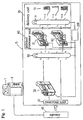
- Fig. 2 is a block diagram showing flows of information and film in the photo processing system;
- Fig. 3 is an explanatory view illustrating an operation at a photo agency and a reception process carried out in time of a reorder;
- Fig. 4 is a perspective view of magnetic information recording areas on an IX240 type photographic film and a cartridge thereof;
- Fig. 5 is a sectional view of a photographic film processor unit;
- Fig. 6 is a schematic view of a transport device;
- Fig. 7 is a schematic view of a printer/processor unit;
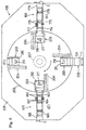
- Fig. 8 is a plan view of a film transport device;
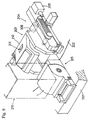
- Fig. 9 is a perspective view of a cartridge loader and a loading unit of the film transport device;
- Fig. 10 is a sectional view of the cartridge loader and loading unit of the film transport device; and
- Fig. 11 is a sectional view of a printing station and a scanning station.
- Fig. 1 shows processes performed of a photographic film in a
cartridge 1 brought to anagency 10 and forwarded to a photo laboratory having a photo processing system S. In the following description, the photo processing system and the photo laboratory are regarded as one and affixed with reference S. Fig. 2 is an explanatory view showing varied processing units constituting the photo processing system S, and flows of printing information, film and printing paper among these units. The flows of the printing information among these units are shown in dotted lines. The data transmitted includes headers representing addresses of the processing units acting as destinations, and data showing the printing information. The printing information always includes a cartridge ID. Thus, a central control may be made of various printing information by using the cartridge ID as a key. - There are mainly two types of
photographic film 2 andfilm container 1 on the market. They are a well-known, 135 type film stored in a cartridge acting as a film holder, and anIX240 type film 2 stored in acartridge 1 acting as a film container, the latter film being based on APS developed recently. This embodiment will be described, taking the IX240 typephotographic film 2 stored in thecartridge 1 and having magnetic information recording areas thereon. - The
agency 10 may receive a request for development and printing of undeveloped photographic film 2 (simultaneous printing), or a request for additional printing or the like of developed photographic film 2 (reorder). In the case of the IX240 type film, thephotographic film 2 after being developed is placed in thespecial cartridge 1 when returned to the customer. - As shown in Fig. 4, the IX240 type
photographic film 2 has magnetic layers forming magneticinformation recording areas 2b above and belowimage areas 2a. The magnetic information recording areas arranged above theimage areas 2a are called a lab track for recording data to be used in processing the film. The magnetic information recording areas arranged below theimage areas 2a are called a camera track for recording information on photos taken with a camera. A leader portion between theforward end 2A andimage areas 2a includes afilm ID 2d in the form of a bar code recorded on the lab track. The magneticinformation recording areas 2b arranged above frames in theimage areas 2a have recorded therein information on the corresponding frames. - When the customer brings the
photographic film 2 to theagency 10 of photo laboratory S and requests development and/or printing, theagency 10 accepts thephotographic film 2 and issues a pressure sensitive order slip in three sheets as shown in Fig. 3. This order slip includes asheet 11 given to the customer for his or her keeping, aconfirmation sheet 12 kept at theagency 10, and asheet 13 given to the photo laboratory S along with thephotographic film 2. - Fig. 3 shows an order slip issued against a reorder. This order slip includes printing information selected by the customer, such as "frame No.", "number of prints", "print size" and "printing paper surface condition" in the form of a plurality of bar codes. The slip further includes columns for entering customer information such as the name, address and telephone number, as well as the name of
agency 10. Thesheet 13 given to the lab includes also a shopname bar code 14 representing an ID code ofagency 10. - The
cartridge 1 has a cartridge ID recorded as abar code 15 on a surface above a film opening thereof and including a bar code number. This bar code number is written in a form readable by a bar-code reader, on the order slip issued against a reorder or an order for simultaneous printing, in order to collate this order slip with thephotographic film 2 brought in by the customer. - Once the bar code number of the cartridge ID has been written as above, the
sheet 13 andphotographic film 2 given to the lab, even when separated from each other, may be collated by using the cartridge ID as a key. Thus, thesheet 13 for the lab and thephotographic film 2 may be separately transmitted from theagency 10 to the photo laboratory S. - The
sheet 13 andphotographic film 2 transmitted to the photo laboratory S are put to a reception process at a receivingunit 20. At the receivingunit 20, a on-slip bar-code reader 21 reads, from thesheet 13, frames to be printed, numbers of prints, print sizes and so on which are example of printing information recorded in bar codes, the shopname bar code 14 and the bar code number. The receivingunit 20 is connected to ahost computer 200 through a network. The printing information is transmitted to thehost computer 200 which acts as an information controller of the photo processing system installed in the photo laboratory S. The cartridge ID ofcartridge 1 is read by a bar-code reader 22 and inputted to thehost computer 200. These bar-code readers host computer 200 stores the printing information as associated with the cartridge ID in memory. - At this point, undeveloped
photographic film 2 for simultaneous printing and developedphotographic film 2 for reorder follow processing routes different in respect of only a developing process. That is, in Fig. 2, the undevelopedphotographic film 2 for simultaneous printing is transported to a detachunit 36 of aphoto processor unit 30 shown in Fig. 5 to be developed there. The developedphotographic film 2 for reorder is transported directly to the printer/processor unit as shown in a handling path P1. - As shown in Fig. 5, the
photo processor unit 30 includes the detachunit 36 for loading thephotographic film 2 and taking thephotographic film 2 out of thecartridge 1, a developing section having processing tanks for developing thephotographic film 2 fed from the detachunit 36, afilm drying section 40 for drying the developedphotographic film 2 with warm air heated by a drying heater and blown by a drying fan, anoutlet 41 for discharging the driedphotographic film 2, and an attachunit 42 for storing thephotographic film 2 discharged, back into thecartridge 1 where thephotographic film 2 was stored originally. - The
film processor unit 30 will be described in greater detail next. Thephotographic film 2 taken out is transported as pinched by a transport roller and idle rollers from the detachunit 36 to the developing section. The developing section includes seven processing tanks filled with treating solutions such as a developer, a bleaching solution, a fixing solution and stabilizing solution, respectively, for successively performing developing processes such as development, bleaching, fixation and so on, andtransport roller units 39 having different lengths for transporting the photographic'film 2. The seven processing tanks 31-35 are arranged in order in a transport direction of thephotographic film 2. The first deep tank is aprocessing tank 31 storing the developer. The next is aprocessing tank 32 storing the bleaching solution. The next two are processingtanks 33 storing the fixing solution. The three shallow tanks are processingtanks 34 storing the stabilizing solution. - The
photographic film 2 developed in the developing section is transported through thefilm drying section 40 andoutlet 41 to the attachunit 42 where thephotographic film 2 is put back into thecartridge 1 where thephotographic film 2 was stored originally. The attachunit 42 includes a bar-code reader for reading the cartridge ID ofcartridge 1, and a bar-code reader for reading the bar code (film ID) recorded on thefilm 1. Results of reading of the two bar codes are outputted to thehost computer 200. When the cartridge ID on thefilm 1 and the film ID recorded on thefilm 1 are found to disagree with those associated at the receivingunit 20, thehost computer 200 gives a warning to the operator. This precludes possibility of thephotographic film 2 being placed in a cartridge other than theoriginal cartridge 1. - As seen from Fig. 2, the detach
unit 36, photographicfilm processor unit 30 and attachunit 42 are all connected to thehost computer 200 for communication therewith. Thus, thehost computer 200 can grasp processing situations ofphotographic film 2. In this embodiment, the detachunit 36 and attachunit 42 are integrated with theprocessor unit 30, but may be formed separately therefrom. Further, thephotographic film 2 taken out at the detachunit 36 may be placed in an intermediate cartridge for developing purposes different from thecartridge 1, and thereafter stored in theoriginal cartridge 1. - Next, the
photographic film 2 for reorder, orphotographic film 2 developed by thephotographic film processor 30, stored in thecartridge 1, is placed in atransport box 57 shown in Fig. 6, to be transported by atransport device 50 to a next,printing station 60. - In this embodiment, the
printing station 60 includes two printer/processor units photographic film 2. Efficiency of the printing process is achieved by using, for example, the printer/processor unit 61 for making ordinary size prints, and the printer/processor unit 62 for making panorama prints on different size printing paper. - For this purpose, when placed on the
transport device 50 shown in Fig. 6, thecartridge 1 is sorted in thetransport box 57 based on the print information. Thetransport box 57 is identified by abar code 57a applied to a front surface thereof. Thisbar code 57a is read by a bar-code reader transport box 57 into a standby opening 59A or 59B corresponding to an appropriate one of the printer/processor units processor unit - The two printer/
processor units processor unit 61 for example. As shown in Fig. 7, the printer/processor unit 61 includes aprinting station 100 for printing image information offilm 2 onprinting paper 113 and outputting results of printing as printing result information, apaper processor 101 for developing exposedprinting paper 113 and sorting the developedprinting paper 113 for eachphotographic film 2, and acontroller 102 for controlling operation of each component and communicating with thehost computer 200. Thecontroller 102 has, connected thereto, aconsole 103 for inputting various control instructions, and amonitor 104 for displaying image information and the like read at ascanning station 115 described hereinafter. - The
printing station 100 includes an exposinglight source 106, alight adjustment filter 107 for adjusting a color balance of irradiating light emitted from the exposinglight source 106, with yellow, magenta and cyan filters movable into and out of an exposing optical path, amirror tunnel 108 for uniformly mixing the colors of the light after the color balance adjustment through thelight adjustment filter 107, aprinting lens 109 for forming images of image information offilm 2 on theprinting paper 113, ashutter 110,transport rollers 111 for transporting theprinting paper 113, and amotor 112 for driving thetransport rollers 111. - The
light adjustment filter 107 and shutter 110 are controlled by thecontroller 102. Positions of the filters oflight adjustment filter 107 and an opening time of theshutter 115, i.e. an exposure time, are controlled according to exposing conditions determined by thecontroller 102. - Next, a
film transport device 105 andscanning station 115 will be described with reference to Figs. 8 through 11. As shown in Fig. 8 which is a plan view, thefilm transport device 105 includes theprinting station 100 and thescanning station 115 for reading the image information offilm 2. Thescanning station 115 has ascanning light source 116, amirror tunnel 117, a reflectingmirror 118 and aCCD camera 119. - The respective components of
film transport device 105 are mounted and supported on abase 201. Aturntable 202 is disposed in a central position to be rotatable clockwise in Fig. 8. Theturntable 202supports loading units 203 arranged in four positions circumferentially thereof and each having acartridge driver 204. Peripherally ofturntable 202 is acartridge loader 205 for loading thecartridge 1 and having a bar-code reader 205a for reading the cartridge ID. Acover 206 is provided to cover substantially the entire area of base 201 (see Fig. 11). Amotor 207 is disposed under the central position ofturntable 202 to drive theturntable 202. - As shown in detail in Fig. 9, each
cartridge driver 204 includes amotor 208 for drawing thefilm 2 out of thecartridge 1 and taking thefilm 2 into thecartridge 1, and asolenoid 209 for opening a light lock ofcartridge 1. As shown in Figs. 9 and 10, theloading unit 203 has apivotable lid 210. Thecartridge loader 205 has acylindrical case 212 for storingcartridges 1 in a vertical arrangement. Thecartridge 1 falling from thecase 212 is transported to theloading unit 203 by arack 213 andpinion 214. - As shown in Fig. 11, the transport path of
scanning station 115 includestransport rollers optical sensor 166, and a magnetic head 67 acting as aninformation reader 167 for reading information such as the printing information recorded on thephotographic film 2. A take-updevice 168 is disposed at a terminal end of the transport path for temporarily winding up thefilm 2. The transport path ofprinting station 100 likewise includestransport rollers optical sensor 177, a writingmagnetic head 178 and a take-updevice 179. - Though not shown in Fig. 11, the transporting line of each photo processing unit for transporting the
photographic film 2 has a bar-code reader 23 for reading thefilm ID 2d, and transmitting, as necessary, thefilm ID 2d ofphotographic film 2 to be printed to the host computer 200 (see Fig. 2). Thehost computer 200 gives a warning to the operator when the printing information controlled by using the cartridge ID as a key indicates that thefilm ID 2d ofphotographic film 2 to be printed disagrees with the cartridge ID corresponding to thephotographic film 2. Such a disagreement is caused by films and printing paper flowing in a wrong order when a recovery operation is carried out manually to in the event of a film transport trouble or the like. - Operation of this
film transport device 105 will be described next. - The
cartridge 1 storing thefilm 2 is fed from thecartridge loader 205 to thefilm transport device 105. First, in the position marked (D) in Fig. 8, the cartridge ID ofcartridge 1 is read in thecartridge loader 205. The information on the cartridge ID is transmitted to thehost computer 200 through thecontroller 102. When the bar-code reader 205a in thecartridge loader 205 fails to read the cartridge ID, thiscartridge 1 is removed from the system. The cartridge ID is manually inputted from theconsole 103, and processing of thefilm 2 stored in thiscartridge 1 is continued. - After the cartridge ID is read in the
cartridge loader 205, thecartridge 1 is transferred to theloading unit 203. This transfer is carried out by thepinion 213 andrack 214. When the transfer to theloading unit 203 is completed, thelid 210 is closed. Thereafter, theturntable 202 is rotated 90 degrees clockwise to position (E) opposed to thescanning station 115 in Fig. 8. At this time, thehost computer 200, in response to the information on the cartridge ID received from thecartridge loader 205, transmits a command to thecontroller 102 to instruct timing of discharging thephotographic film 2 from theloading unit 203. Based on this timing command, thecontroller 102 transmits thephotographic film 2 to thescanning station 115. Subsequently, thescanning station 115 reads the image information offilm 2, and the information reader 67 reads the magnetic information. - The image information read is transmitted to the
controller 102. Based on the image information read from thefilm 2, thecontroller 102 determines printing conditions for each frame. Each image expected to result from exposure made on theprinting paper 113 with the printing conditions determined is simulated and displayed on themonitor 104. - The operator of the printer/
processor 61 may observe images displayed on themonitor 104, and input instructions to correct the exposing conditions through theconsole 103 unless proper images are obtained. Then, thecontroller 102 corrects the exposing conditions based on the correcting instructions and determines final exposing conditions. When the processing at thescanning station 115 is completed, theturntable 202 transports thecartridge 1 through position (F) to position (G), i.e. theprinting station 100 as shown in Fig. 8. Then, the image information offilm 2 are printed, and the magnetic information is written. The data taken in at thescanning station 115 is transmitted to anindex printer 220 as shown in Fig. 2, where the data is processed digitally for index printing. When the processing at theprinting station 100 is completed, theturntable 202 returns thecartridge 1 to thecartridge loader 205, from which thecartridge 1 is transported to adelivery unit 70 shown in Fig. 1. - In the printing step, a communication is made with the
host computer 200 to determine if the printing information, such as print size or trimming value, read by theinformation reader 167 is applicable to the frames to be exposed. If the printing information is applicable to the frames, an exposing process is performed by taking this printing information into account. Where the printing information, e.g. the number of prints, acquired through the receivingunit 20 is applicable to the frames to be exposed, an exposing process is performed by taking this printing information into account, and these frames are printed in the process acquired through the receivingunit 20. That is, the film images are printed on the printing paper based on the printing information acquired through the receivingunit 20, the printing information read by theinformation reader 167, and the above-mentioned printing conditions. - On the other hand, the cartridge ID and frame numbers read in the
cartridge loader 205 are printed on the reverse surface of exposedprinting paper 113 by arecorder 222. In thepaper processor 101, theprinting paper 113 is developed, and the developedprinting paper 113, i.e. finished prints, is/are sorted into each order (a group of prints of images included in one photographic film 2), and transported to thedelivery unit 70. Aslip issue unit 225 is in communication with thehost computer 200 through the network, and issues a slip based on printing result information such as the number of prints outputted from theprinting station 100 of the printer/processor unit 61 and information inputted at the receivingunit 20. - The
delivery unit 70 includes atransport device 71 and adelivery station 72. Thistransport device 71 may have the same basic construction as thetransport device 50 shown in Fig. 6. At thedelivery station 72, thephotographic film 2 stored in thecartridge 1 transported from the printer/processor unit 61, the prints corresponding to thephotographic film 21, the index print and the slip received from theslip issue unit 225 are collated with the cartridge ID, and collected in product packets for each customer transmitted directly from the receivingunit 20 as shown by a handling path P2 (Fig. 2). Such product packets are sorted for eachagency 10. When the sorting is completed, the prints andcartridge 2 are forwarded to theagency 10.
Claims (6)
- A photographic printing system for a photographic film stored in a cartridge with a cartridge ID, comprising:a first reader (21) for reading, from an order sheet (13), first printing information including frames to be printed and print sizes and said cartridge ID;a first cartridge ID reader (22) for reading said cartridge ID from said cartridge;a host computer (200) for storing said first printing information as associated with said cartridge ID, based on the read information from said first reader (21) and said first cartridge ID reader (22);a cartridge loader (205) for loading said cartridge, said cartridge loader (205) having a second cartridge ID reader (205a) for reading said cartridge ID from said cartridge loaded into said cartridge loader;a loading unit for drawing said photographic film out of said cartridge loaded into said cartridge loader (205), said loading unit including a second reader (166, 167) for reading information recorded on the photographic film drawn out of the cartridge;a printing station (100) for printing images of said photographic film on printing paper; anda film ID reader (23) for reading a film ID recorded on said photographic film;
characterized in that
the information recorded on the photographic film and read by said second reader (166, 167) of said loading unit comprises second printing information including print size or trimming value;
said host computer (200) generates and stores third printing information as associated with said cartridge ID based on the read-information from said second cartridge ID reader (205a) and said second reader (166, 167), said third printing information being a combination of said first printing information and said second printing information;
said printing station (100) effects the printing of the images based on said third printing information; and
said host computer (200) communicates, by using said cartridge ID as a key, with said printing station (100) in timed relationship with an operation thereof, to control printing result information including the number of prints, for each said cartridge ID. - The photographic printing system according to claim 1, further characterized in that said second reader of said loading unit includes a magnetic head (167) for reading the second printing information such as print size, trimming value, magnetically recorded in a magnetic layer of the photographic film.
- The photographic printing system according to claim 1 or 2, further characterized in that said host computer (200) collates said film ID of said photographic film to be processed with said cartridge ID corresponding to said photographic film and gives an alarm when a disagreement occurs between said film ID and said cartridge ID.
- The photographic printing system according to any one of claims 1-3, further characterized in that there is provided a recorder (222) for recording, on said printing paper, at least a portion of said third printing information and said cartridge ID.
- The photographic printing system according to any one of claims 1-4, further characterized in that there is provided a slip issue unit (225) for issuing a delivery slip, wherein said host computer (200) generates delivery slip information based on said first printing information and said printing result information, and sends said delivery slip information to said slip issue unit (225).
- The photographic printing system according to claim 5, further characterized that there is provided a delivery unit (70) for delivering a combination of said cartridge, finish prints, and said delivery slip issued by said slip issue unit (225), said delivery unit (70) being capable of communicating with said host computer (200) by using said cartridge ID as a key, to collate said cartridge, finish prints and said delivery slip based on said cartridge ID.
Applications Claiming Priority (3)
| Application Number | Priority Date | Filing Date | Title |
|---|---|---|---|
| JP25808297 | 1997-09-24 | ||
| JP258082/97 | 1997-09-24 | ||
| JP9258082A JPH1195331A (en) | 1997-09-24 | 1997-09-24 | Photographic processing system |
Publications (3)
| Publication Number | Publication Date |
|---|---|
| EP0907100A2 EP0907100A2 (en) | 1999-04-07 |
| EP0907100A3 EP0907100A3 (en) | 2001-07-04 |
| EP0907100B1 true EP0907100B1 (en) | 2006-03-01 |
Family
ID=17315277
Family Applications (1)
| Application Number | Title | Priority Date | Filing Date |
|---|---|---|---|
| EP98117829A Expired - Lifetime EP0907100B1 (en) | 1997-09-24 | 1998-09-21 | Photographic printing method and photographic printing system for photographic film stored in a cartridge |
Country Status (4)
| Country | Link |
|---|---|
| US (1) | US6055037A (en) |
| EP (1) | EP0907100B1 (en) |
| JP (1) | JPH1195331A (en) |
| DE (1) | DE69833593T2 (en) |
Families Citing this family (7)
| Publication number | Priority date | Publication date | Assignee | Title |
|---|---|---|---|---|
| US6515732B1 (en) * | 2000-06-26 | 2003-02-04 | Eastman Kodak Company | Photofinishing method and system |
| EP1231508A1 (en) | 2001-02-08 | 2002-08-14 | SYSTEL INTERNATIONAL S.p.A. | Photo finishing system with parallel cutter arrangement |
| US20030200099A1 (en) * | 2002-04-17 | 2003-10-23 | Eastman Kodak Company | Method and system for providing imaging services to a digital order |
| US6601760B1 (en) | 2002-06-11 | 2003-08-05 | Eastman Kodak Company | System and method for delivering photographic-based products to a customer |
| JP2004264375A (en) * | 2003-02-25 | 2004-09-24 | Konica Minolta Holdings Inc | Method and system for print production, print order sheet, print storage bag and print product |
| JP2005251026A (en) * | 2004-03-05 | 2005-09-15 | Noritsu Koki Co Ltd | Order receiving system |
| US8117388B2 (en) * | 2009-04-30 | 2012-02-14 | Netapp, Inc. | Data distribution through capacity leveling in a striped file system |
Family Cites Families (9)
| Publication number | Priority date | Publication date | Assignee | Title |
|---|---|---|---|---|
| JP2547461B2 (en) * | 1990-02-15 | 1996-10-23 | 富士写真フイルム株式会社 | Photo printing equipment |
| US5752114A (en) * | 1992-03-17 | 1998-05-12 | Sony Corporation | Photographic and video image system |
| JP2976741B2 (en) * | 1993-02-24 | 1999-11-10 | ノーリツ鋼機株式会社 | Photo processing method |
| US5831714A (en) * | 1994-01-31 | 1998-11-03 | Fuji Photo Film Co., Ltd. | Photographic processing system and collating system |
| US5576794A (en) * | 1994-05-12 | 1996-11-19 | Eastman Kodak Company | Random batch photofinishing |
| JPH0922074A (en) * | 1995-07-10 | 1997-01-21 | Fuji Photo Film Co Ltd | Photographic processing system |
| JPH0950083A (en) * | 1995-08-04 | 1997-02-18 | Fuji Photo Film Co Ltd | Photograph processing system |
| EP0793142B1 (en) * | 1996-03-01 | 2001-09-12 | Noritsu Koki Co., Ltd. | Photographic processing system comprising means for automatically sorting films according to parameters read from the films |
| JP3670384B2 (en) * | 1996-03-22 | 2005-07-13 | 富士写真フイルム株式会社 | Photographic film cartridge manufacturing information management method |
-
1997
- 1997-09-24 JP JP9258082A patent/JPH1195331A/en active Pending
-
1998
- 1998-09-21 EP EP98117829A patent/EP0907100B1/en not_active Expired - Lifetime
- 1998-09-21 DE DE69833593T patent/DE69833593T2/en not_active Expired - Fee Related
- 1998-09-21 US US09/157,642 patent/US6055037A/en not_active Expired - Fee Related
Also Published As
| Publication number | Publication date |
|---|---|
| DE69833593D1 (en) | 2006-04-27 |
| DE69833593T2 (en) | 2006-12-21 |
| US6055037A (en) | 2000-04-25 |
| EP0907100A2 (en) | 1999-04-07 |
| EP0907100A3 (en) | 2001-07-04 |
| JPH1195331A (en) | 1999-04-09 |
Similar Documents
| Publication | Publication Date | Title |
|---|---|---|
| EP0672949B1 (en) | Film information communication apparatus, film information printing apparatus, information processing apparatus and index printer | |
| EP0614117B1 (en) | Photographic processing method | |
| JPH03237447A (en) | Photographic printer | |
| EP0907100B1 (en) | Photographic printing method and photographic printing system for photographic film stored in a cartridge | |
| US5825467A (en) | Order form for photographic prints, keyboard, reprinting method and reordering method | |
| US5729328A (en) | Photographic film inspection apparatus | |
| US5995196A (en) | Reorder processing system | |
| JPH1130818A (en) | Negative film with id number and photograph printing device | |
| JPH0950083A (en) | Photograph processing system | |
| EP0622679A1 (en) | Photographic processing method | |
| JP2593228B2 (en) | Film cutting inserter and photographic printing method | |
| US6396564B2 (en) | Photographic printing system and photographic printing method | |
| JPH1020406A (en) | Reorder system | |
| JPH05289184A (en) | Method for producing printed photograph | |
| JPH08190152A (en) | Index print preparing supplying device and photographic printing developing device | |
| JPH08152704A (en) | Method for collating photographic materials in photograph processing system | |
| JP2006065075A (en) | Image formation system and hand-over system using same image formation system | |
| JPH10206980A (en) | Printer processor | |
| JPH10301211A (en) | Photographic printer | |
| JPH04241344A (en) | Formation of printed photograph and dp bag | |
| JPH07248599A (en) | Device for receiving photographic processing request | |
| JPH05289182A (en) | Photograph printer for intermingled frame | |
| JPH05289185A (en) | Billing machine | |
| JPH03214158A (en) | Photographic printing method | |
| JPH04147260A (en) | Method for collating printed photograph |
Legal Events
| Date | Code | Title | Description |
|---|---|---|---|
| PUAI | Public reference made under article 153(3) epc to a published international application that has entered the european phase |
Free format text: ORIGINAL CODE: 0009012 |
|
| 17P | Request for examination filed |
Effective date: 19980922 |
|
| AK | Designated contracting states |
Kind code of ref document: A2 Designated state(s): DE FR GB |
|
| AX | Request for extension of the european patent |
Free format text: AL;LT;LV;MK;RO;SI |
|
| PUAL | Search report despatched |
Free format text: ORIGINAL CODE: 0009013 |
|
| AK | Designated contracting states |
Kind code of ref document: A3 Designated state(s): AT BE CH CY DE DK ES FI FR GB GR IE IT LI LU MC NL PT SE |
|
| AX | Request for extension of the european patent |
Free format text: AL;LT;LV;MK;RO;SI |
|
| AKX | Designation fees paid |
Free format text: DE FR GB |
|
| 17Q | First examination report despatched |
Effective date: 20040707 |
|
| GRAP | Despatch of communication of intention to grant a patent |
Free format text: ORIGINAL CODE: EPIDOSNIGR1 |
|
| GRAS | Grant fee paid |
Free format text: ORIGINAL CODE: EPIDOSNIGR3 |
|
| GRAA | (expected) grant |
Free format text: ORIGINAL CODE: 0009210 |
|
| AK | Designated contracting states |
Kind code of ref document: B1 Designated state(s): DE FR GB |
|
| REG | Reference to a national code |
Ref country code: GB Ref legal event code: FG4D |
|
| REF | Corresponds to: |
Ref document number: 69833593 Country of ref document: DE Date of ref document: 20060427 Kind code of ref document: P |
|
| PLBE | No opposition filed within time limit |
Free format text: ORIGINAL CODE: 0009261 |
|
| STAA | Information on the status of an ep patent application or granted ep patent |
Free format text: STATUS: NO OPPOSITION FILED WITHIN TIME LIMIT |
|
| 26N | No opposition filed |
Effective date: 20061204 |
|
| EN | Fr: translation not filed | ||
| GBPC | Gb: european patent ceased through non-payment of renewal fee |
Effective date: 20060921 |
|
| PG25 | Lapsed in a contracting state [announced via postgrant information from national office to epo] |
Ref country code: GB Free format text: LAPSE BECAUSE OF NON-PAYMENT OF DUE FEES Effective date: 20060921 |
|
| PG25 | Lapsed in a contracting state [announced via postgrant information from national office to epo] |
Ref country code: FR Free format text: LAPSE BECAUSE OF FAILURE TO SUBMIT A TRANSLATION OF THE DESCRIPTION OR TO PAY THE FEE WITHIN THE PRESCRIBED TIME-LIMIT Effective date: 20060301 |
|
| PGFP | Annual fee paid to national office [announced via postgrant information from national office to epo] |
Ref country code: DE Payment date: 20081002 Year of fee payment: 11 |
|
| PG25 | Lapsed in a contracting state [announced via postgrant information from national office to epo] |
Ref country code: DE Free format text: LAPSE BECAUSE OF NON-PAYMENT OF DUE FEES Effective date: 20100401 |