EP0906881B2 - Singulating apparatus for a mail handling system - Google Patents
Singulating apparatus for a mail handling system Download PDFInfo
- Publication number
- EP0906881B2 EP0906881B2 EP98118650A EP98118650A EP0906881B2 EP 0906881 B2 EP0906881 B2 EP 0906881B2 EP 98118650 A EP98118650 A EP 98118650A EP 98118650 A EP98118650 A EP 98118650A EP 0906881 B2 EP0906881 B2 EP 0906881B2
- Authority
- EP
- European Patent Office
- Prior art keywords
- articles
- nip
- feed
- force
- stack
- Prior art date
- Legal status (The legal status is an assumption and is not a legal conclusion. Google has not performed a legal analysis and makes no representation as to the accuracy of the status listed.)
- Expired - Lifetime
Links
Images


Classifications
-
- B—PERFORMING OPERATIONS; TRANSPORTING
- B65—CONVEYING; PACKING; STORING; HANDLING THIN OR FILAMENTARY MATERIAL
- B65H—HANDLING THIN OR FILAMENTARY MATERIAL, e.g. SHEETS, WEBS, CABLES
- B65H3/00—Separating articles from piles
- B65H3/46—Supplementary devices or measures to assist separation or prevent double feed
- B65H3/52—Friction retainers acting on under or rear side of article being separated
- B65H3/5246—Driven retainers, i.e. the motion thereof being provided by a dedicated drive
-
- B—PERFORMING OPERATIONS; TRANSPORTING
- B65—CONVEYING; PACKING; STORING; HANDLING THIN OR FILAMENTARY MATERIAL
- B65H—HANDLING THIN OR FILAMENTARY MATERIAL, e.g. SHEETS, WEBS, CABLES
- B65H2511/00—Dimensions; Position; Numbers; Identification; Occurrences
- B65H2511/10—Size; Dimensions
- B65H2511/13—Thickness
-
- B—PERFORMING OPERATIONS; TRANSPORTING
- B65—CONVEYING; PACKING; STORING; HANDLING THIN OR FILAMENTARY MATERIAL
- B65H—HANDLING THIN OR FILAMENTARY MATERIAL, e.g. SHEETS, WEBS, CABLES
- B65H2511/00—Dimensions; Position; Numbers; Identification; Occurrences
- B65H2511/50—Occurence
- B65H2511/51—Presence
-
- B—PERFORMING OPERATIONS; TRANSPORTING
- B65—CONVEYING; PACKING; STORING; HANDLING THIN OR FILAMENTARY MATERIAL
- B65H—HANDLING THIN OR FILAMENTARY MATERIAL, e.g. SHEETS, WEBS, CABLES
- B65H2515/00—Physical entities not provided for in groups B65H2511/00 or B65H2513/00
- B65H2515/30—Forces; Stresses
- B65H2515/34—Pressure, e.g. fluid pressure
-
- B—PERFORMING OPERATIONS; TRANSPORTING
- B65—CONVEYING; PACKING; STORING; HANDLING THIN OR FILAMENTARY MATERIAL
- B65H—HANDLING THIN OR FILAMENTARY MATERIAL, e.g. SHEETS, WEBS, CABLES
- B65H2701/00—Handled material; Storage means
- B65H2701/10—Handled articles or webs
- B65H2701/19—Specific article or web
- B65H2701/1916—Envelopes and articles of mail
Definitions
- the processing and handling of mailpieces consumes an enormous amount of human and financial resources, particularly if the processing of the mailpieces is done manually.
- the processing and handling of mailpieces not only takes place at the Postal Service, but also occurs at each and every business or other site where communication via the mail delivery system is utilized. That is, various pieces of mail generated by a plurality of departments and individuals within a company need to be collected, sorted, addressed, and franked as part of the outgoing mail process. Additionally, Incoming mail needs to be collected and sorted efficiently to ensure that it gets to the addressee in a minimal amount of time.
- mixed mail is used herein to mean sets of intermixed mailpieces of varying size (postcards to 22.9 cm by 30.5 cm (9" by 12") flats), thickness, and weight.
- mixed mail also includes stepped mail (i.e. an envelope containing therein an insert which is smaller than the envelope to create a step in the envelope), tabbed and untabbed mail products, and mailpieces made from different substrates.
- One singulator known from US-A-4,909,499 comprises a feed deck; forwardly driving means, connected to the feed deck, for contacting successive articles along a first surface thereof and for advancing the articles in a first direction along the feed path and over the feed deck; and a reverse driving mechanism, connected to the feed deck, for contacting the articles along a second surface thereof and for applying driving force to the articles in a second direction opposite to the first direction whereby only one of the articles at a time is moved by the forwardly driving means In the first direction along the feed path and over the feed deck, the forwardly driving means and the reverse driving mechanism being connected to the feed deck relative to each other to define a nip for ingestion of articles therebetween.
- the stack of "mixed mail" is first loaded onto some type of conveying system for subsequent sorting into individual pieces.
- the stack of mixed mail is moved as a stack by an external force to, for example, a shingling device.
- the shingling device applies a force to the lead mailpiece in the stack to initiate the separation of the lead mailpiece from the rest of the stack by shingling it slightly relative to the stack.
- the shingled mailpieces are then transported downstream to, for example, a separating device which completes the separation of the lead mailpiece from the stack so that individual pieces of mail are transported further downstream for subsequent processing.
- inter-document stack forces exist between each of the mailpieces that are in contact with each other in the stack.
- the inter-document stack forces are created by the stack advance mechanism, the frictional forces between the documents, and potentially electrostatic forces that may exist between the documents.
- the inter-document forces tend to oppose the force required to shear the lead mailpiece from the stack.
- the interaction of the force used to drive the shingled stack toward the separator and the separator forces can potentially cause a thin mailpiece to be damaged as it enters the separator.
- the structure used to separate a stack of mixed mail must take into account the counterproductive nature of the forces acting on the mailpieces and be such that an effective force profile acts on the mailpieces throughout theirprocessing cycle so that effective and reliable mailpiece separation and transport at very high processing speeds (such as four mailpieces per second) can be accomplished without physical damage occurring to the mailpieces.
- the desired force profile acting on a particular mailpiece is dependent upon the size, thickness, configuration, weight, and substrate of the individual mailpiece being processed, the design of a mixed mail feeder which can efficiently and reliably process a wide range of different types of mixed mailpieces has been extremely difficult to achieve.
- Mixed mail feeder 1 separates individual mailpieces 3 from a stack of mixed mail generally designated at 5 and transports the individual mailpieces 3 to a subsequent mail processing station 7.
- Mail processing station 7 can be any one of a plurality of devices such as a meter for printing postage on the mailpiece 3, an OCR reader for reading addresses off of the mailpiece 3, a sorting device for sorting the individual mailpieces 3 to designated bins or areas, or even a scale that weighs the mailpiece.
- the key point is that the mixed mail feeder 1 functions to separate individual mailpieces 3 from a stack of mixed mail 5 and deliver the individual mailpieces 3 sequentially to the mail processing station 7.
- Mixed mail feeder 1 includes a table 9 upon which all of the components of the mixed mail feeder 1 are mounted. At an input end of the mixed mail feeder 1, generally designated by the arrow 11, the stack of mixed mail 5 is placed on edge by an operator in front of a guide wall 13. Guide wall 13 acts as a support against which the stack of mixed mail 5 rests. Moreover, guide wall 13 includes a cylindrical portion 13a which is mounted to slide on a guide rod 15 fixedly attached to platform 10 which is mounted to table 9.
- Platform 10 has first and second slots 17, 19, in a horizontal surface 21 thereof.
- the slots 17, 19 each permit a top portion of a respective individual continuous belt 23, 25 to project therethrough.
- Belts 23, 25 each have a plurality of individual track portions 27 over the full extent of the belts 23, 25.
- the bottom of guide wall 13 removably fits in adjacent track portions 27 of each of belts 23 and 25 so that guide wall 13 moves with belts 23, 25 in the direction of arrow A.
- the cylindrical portion 13a slides along guide rod 15 to keep the standing orientation of guide wall 13 in the position shown in Fig. 1.
- Continuous belts 23, 25 are mounted in a conventional manner around a pulley at each end (not shown).
- One pulley is an idler pulley while the other is driven by a motor 29.
- the motor 29 drives a common shaft (not shown) connected to the drive pulleys of each of the belts 23, 25 such that the belts 23,25 will be driven at the same velocity to move around their respective idler and driven pulleys.
- the guide wall 13 moves therewith so that the entire stack of mixed mail 5 is moved toward a nudger wall 31.
- the stack of mixed mail 5 will have individual mailpieces 3 moved from the stack downstream so that the stack of mixed mailpieces is continuously reduced in size.
- the guide wall 13 can be lifted out of the individual tracks 27 of the belts 23, 25 by pulling the guide wall 13 up to rotate, via the cylindrical portion 13a, about the guide rod 15. Once the bottom of the guide wall 13 is clear of the individual tracks 27 of the belts 23, 25, it can be slid backward in the opposite direction from that of arrow A and placed in a desired position to receive additional mixed mail.
- nudger wall 31 includes a plurality of rollers 33 mounted therein in a conventional manner to be freely rotatable. Furthermore, nudger wall 31 has a cutout 35 in a lower corner thereof through which driven nudger rollers 37 project. Moreover, a plurality of roller bars 38 are rotatably mounted in a conventional manner in a slot 40 of platform 10.
- a continuous belt (not shown) is driven around the roller bars 38. The use of the continuous belt provides a greater coefficient of friction as compared to the roller bars and thus improves the feed force and provides for a simple drive structure.
- the nudger rollers 37 are mounted to be driven into rotation within a nudger arm 39.
- the four nudger rollers 37 are driven together by a motor 41, mounted on nudger arm 39, via a drive train 43 as shown schematically in Figure 2 and in detail in Figure 4.
- all of the nudger rollers 37 are driven into rotation in a clockwise direction. Accordingly, as the stack of mixed mail 5 is moved toward nudger wall 31, the lead mailpiece 3a is forced into contact with the nudger rollers 37.
- the force of the driven nudger rollers 37 acts against the lead mailpiece 3a to move the mailpiece 3a in the direction of a separator device 45, thereby shingling the lead mailpiece 3a from the stack of mixed mail 5 as shown in Figures 1 and 2.
- the shingled stack is then transported to the nip 46 of separator 45 which separates the lead mailpiece 3a from the shingled stack and delivers it to take-away rollers 65 which transport the individual lead mailpiece 3a further downstream to mail processing station 7.
- Motor 41 has a shaft 41 a connected to a pulley 42.
- a continuous belt 44 is disposed around pulley 42 and a second pulley 46.
- Pulley 46 is fixedly mounted to a rotatable shaft 48 mounted in nudger arm 39.
- Fixedly mounted to shaft 48 is a third pulley 50.
- Additional shafts 52, 54 are also rotatably mounted in nudger arm 39 and respectively have fourth and fifth pulleys 56, 58 fixedly mounted thereto.
- Nudger rollers 37 are mounted on a corresponding one of shafts 52,54. Accordingly, as motor 41 rotates pulley 42 in the clockwise direction of Fig.
- pulley 46 and hub 48 are drive in the clockwise direction as well. Since a continuous belt 60 passes around pulleys 48, 56, and 58, shafts 52, 54 are forced to rotate in the clockwise direction causing a corresponding rotational movement in all of nudger rollers 37.
- the normal force is created by a spring 49 that is fixedly mounted at one end to the nudger wall 31 and at its other end to a mounting platform 50 of nudger arm 39.
- the nudger arm 39 is pivotally mounted about a conventional pivot structure 51 so that the spring 49 biases the nudger rollers 37 through the cutout 35 and into contact with the lead mailpiece 3a.
- the separator 45 As the thin and untabbed mailpieces are fed by the nudger rollers 37 into,the separator 45, they can easily be buckled and damaged due to the feeding force of the nudger rollers 37 and the forces exerted by separator 45. Additionally, if the guide wall 13 is advanced too far toward the nudger wall 31 the stack of mixed mail 5 will be clamped in place preventing the feeding of individual mailpieces from stack 5. To preventthis from happening, the contact point of the nudger rollers 37 against the lead mailpiece 3a is always maintained closer to the stack 5 than the facing surface of the nudger wall 31 is to the stack 5.
- the normal force which is created by the positioning of the mailpiece stack 5 against the nudger rollers 37 and the corresponding force created by the extension of spring 49 needs to be maintained in an approximate range of 1-2 newtons in orderto ensure that the various types of mixed mailpieces 3 which may be processed are properly shingled and fed vertically into the throat of separator 45 without being damaged or stalled at nudger wall 31.
- the normal force is provided by the extension of spring 49, it can be controlled by accurately regulating the position of nudger arm 39 which correspondingly regulates the extension of spring 49. That is, since the normal force applied by spring 49 is directly proportional to its extension, the normal force that it applies to the stack of mixed mail 5 is controlled by regulating the extension of spring 49.
- the aforementioned control of the extension of spring 49 and rotation of nudger arm 39 is accomplished via the utilization of conventional through-beam sensors 53, 55, and 57 and a finger 59 which projects from nudger arm 39.
- the finger 59 will move between the three sensors 53, 55 and 57.
- a signal is sent by the respective blocked through-beam sensor to a mixed mail feeder microprocessor 61 indicating the position of the finger 59 at the blocked sensor.
- the known position of the finger 59 corresponds to a known position of the nudger arm 39 and a known amount of extension of the spring 49.
- the microprocessor 61 If the finger 59 is blocking the beam of the first sensor 53, the microprocessor 61 knows that the nudger rollers 37 are at their innermost position relative to the stack of mixed mail 5. At this position, the normal force exerted by spring 49 is below the desired minimum value of I newton and must be increased. The increase in normal force is created when the microprocessor 61, in response to a signal from sensor 53, energizes the motor 29 to move the belts 23 and 25 such that the guide wall 13 advances the mixed mail stack 5 into the nudger rollers 37. The motor 29 will advance the stack of mixed mail 5 until the nudger arm 39 pivots about pivot structure 51 to the position where finger 59 blocks the through-beam sensor 55.
- the sensor 55 sends a signal to microprocessor 61 which in turn deenergizes motor 29 stopping the advance of the stack of mixed mail 5 toward the nudger rollers 37.
- the nudger rollers 37 are considered to be in the "out" position where the maximum desired normal force is being exerted on the lead mailpiece 3a due to the extension of the spring 49.
- the nudger rollers 37 gradually move toward the innermost normal force position.
- microprocessor 61 When the nudger arm 39 has rotated inwardly such that the nudger rollers 37 are in the innermost normal force position, microprocessor 61 receives a signal from sensor 53 and energizes motor 29 to advance the stack of mail 5 until the second sensor 55 is blocked by the finger 59. In this manner, constant regulation of the normal force in the predetermined range is maintained.
- the automatic control of the normal force would only use the sensors 53 an d 55 to ensure that the normal force generated by the nudger rollers 37 stays within the predetermined desired normal force range.
- a second tier of additional stack force can be applied if it is determined that a mailpiece 3 has stalled at the nudger rollers 37 or at the separator 45. That is, it is possible, since the mixed mail feeder 1 is designed to handle many different types of mixed mail, that a very heavy piece of mail may have stalled (become stuck) at the nudger rollers 37 or separator 45.
- the mixed mail feeder 1 determines that a stall has occurred is by the use of a through-beam sensor 63, which is positioned proximate to the nip of takeaway rollers 65. Takeaway rollers 65, in a conventional manner, receive individual mailpieces from separator 45 and move the individual mailpieces 3 downstream.
- the takeaway rollers 65 feed a first mailpiece and do not process a second mailpiece 3 downstream in a predetermined period of time of, for example, 1,000 msec
- the through-beam of sensor 63 does not detect the lead edge of the second mailpiece during that same predetermined time period. If the microprocessor 61 does not receive an indication from the sensor 63 that a leading edge of the second mailpiece has passed thereby within the predetermine period of time, microprocessor 61 is programmed to assume that a stall has occurred somewhere upstream. Microprocessor 61 then energizes motor 29 to cause the stack of mixed mail 5 to be moved toward the nudger wall 31. The nudger arm 39 Is forced rotate about the pivot point 51 and the spring 49 is further extended.
- nudger arm 39 is advanced to block the third sensor 57.
- a stalled normal force which is larger than the maximum normal force applied under normal operating conditions, is being exerted on the lead mailpiece 3a by the nudger rollers 37 and the motor 29 is rendered inoperative by microprocessor 61.
- the increased normal force can simply be due to the further extension of the spring 49 as the nudger arm 39 is rotated from its position blocking sensor 55 to its position blocking sensor 57, or can be further increased by the force of an additional compression spring 66 which only contacts the nudger arm 39 to provide an additional spring force thereto when the nudger arm 39 moves beyond the position from the blocking of sensor 55 toward the blocking of sensor 57.
- the takeaway sensor 63 will provide an input to the microprocessor 61 identifying that the lead edge of the stalled mailpiece has passed thereby and the processing of individual mailpieces 3 will continue by driving the nudger rollers 37 until the nudger arm 39 moves to a position where the first sensor 53 is blocked by finger 59. At this position, the system will operate as discussed above, regulating a force profile by maintaining the position of nudger arm 39 between the sensors 53 and 55.
- the microprocessor 61 In the event however, that even the additional normal force provided by the movement of the nudger arm 39 to block the sensor 57 does not correct the stalled problem, the microprocessor 61, after a predetermined period of time, will provide an input to the user via a display 67 identifying the stalled condition and advising that operator intervention is required to correct the problem.
- the microprocessor 61 controls all of the motors typically associated with the stack advance, shingling device, separator, and take away rollers and includes known clock structure for determining the predetermined time periods discussed above. Empirical testing has shown that for the anticipated mixed mailpiece profile the additional normal force applied during movement of finger 59 from sensor 55 to sensor 57 goes from 2 to 5 newtons.
- a different mechanism is used to provide additional force in the situation where stalled mail is detected. That is, once the microprocessor 61 determines that a stall has occurred, utilization of a solenoid 71 and another spring 73 provides additional normal force in an attempt to overcome the stalled situation.
- the solenoid 71 is fixedly mounted to the platform 9 and the spring 73 has one end fixedly mounted to the nudger arm 39 and a second end fixedly mounted to a moveable plunger 75 of solenoid 71.
- the spring 73 is slack, thereby providing no additional normal spring force.
- the microprocessor 61 energizes the solenoid 71 to withdraw the plunger 75 such that the spring 73 is extended to provide an additional normal force to the mixed mail stack 5 via the nudger rollers 37.
- the force applied by the solenoid/spring combination 71/73 can be consistently applied for a predetermined period of time or can be pulsed to help the stalled mail break away.
- different levels of force can be applied by the spring 73 and solenoid 71 combination over a predetermined time period in an attempt to break the stalled mailpiece away.
- separator 45 includes a reverse belt assembly 105 and a feed belt assembly 107.
- Feed belt assembly 107 is fixedly mounted to a feed deck 109.
- Shafts 111, 113, and 115 are fixedly mounted in feed deck 109 and end plate 117.
- Clips 119 retain shafts 111, 113 and 115 in end plate 117 while shaft 111 is mounted for rotation therein.
- Pulley assemblies 121, 123, and 125 are respectively mounted on shafts 111, 113, and 115 to be rotatable thereabout.
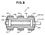
- Figures 7 and 8 respectively show the mounting structure of the driven pulley 121 and the idler pulleys 123/125.
- each of the idler pulley assemblies 123/125 is mounted on ball bearings 235 about their respective shafts 113/115.
- Driven pulley assembly 121 is also mounted on ball bearings 235 but is also mounted on an overrunning clutch 233 for purposes to be discussed later.
- Each pulley assembly 121/123/125 has three serrated, crowned hub portions 126 around which a respective one of each of three continuous belts 127 is disposed.
- a bracket 129 has a free end 131 at which a roller 133 is mounted for rotation and a second end 135 which is pivotably mounted to a bracket 137 which itself is fixedly mounted to feed deck 109.
- a spring 139 has a first end 141 connected to the second end 135 of bracket 129 and a second end 143 fixedly mounted within the mail handling machine. Spring 139 biases roller 133 into belt 127 to maintain a proper belt tension. As shown in Figure 6, there is a tension roller 133 for each belt 127.
- the feed belt assembly 107 is driven by a motor 147 which is controlled by microprocessor 61.
- a shaft 149 is driven by motor 147 and in turn drives a pulley 151 which is fixedly mounted to shaft 149.
- a continuous belt 153 is disposed around pulley 151 and also around a pulley 155 fixedly mounted to a lower portion of shaft 111 which extends below deck 109.
- pulley 151, pulley 155, shaft 111, and pulley assembly 121 also rotate in the clockwise direction.
- the clockwise rotation of pulley assembly 121 causes belts 127 to move in the clockwise direction with idler pulley assemblies 123/125, thereby feeding the lead mailpiece 3a toward the take away rollers 65.
- Feed belt assembly 107 also includes a guide 157 fixedly attached to feed deck 109.
- Guide 157 includes 4 fingers 159 which extend on either side of the three feed belts 127.
- the guide 157 prevents the mailpieces from hitting and getting caught on the three belts 127 and guides the mailpieces 3 toward separator nip 46. This prevents the mailpieces 3 from being routed behind feed belt apparatus 107.
- Reverse belt assembly 105 includes a mailpiece ingestion guide plate 163 that is pivotably mounted to feed deck 109 and biased toward mailpieces 3 by spring 165.
- Spring 165 is connected to a post 167 fixed to base 109.
- Ingestion guide 163 is mounted on and pivots about a shaft 169 which itself is fixedly mounted at one end in feed deck 109.
- Middle finger 176 prevents mail from curling up between the reverse belt assembly retard belts 175. It is important to note that the positioning of the biased ingestion guide 163 within nip 46 helps to solve two fundamental problems associated with the separation and feeding of mixed mail.
- a through-beam sensor 101 is located just upstream from nip 46. The sensor provides an indication to microprocessor 61 as to whether a mailpiece 3 is present.
- microprocessor 61 If no mailpiece is sensed as being present microprocessor 61 operates the nudger rollers 37 to continue feeding mailpieces 3 toward the nip 46. However, if sensor 101 senses the presence of a mailpiece 3, microprocessor 61 stops the feeding of mailpieces by nudger rollers 37. Since the mailpieces are only being acted upon by the separator 45 and not the nudger rollers 37, it is less likely that thin mailpieces will curl up in the nip. However when the nudger rollers 37 are stopped, the sensed mailpiece has not been fully ingested in nip 46 and it is possible that in some instances the feed belts 127 will not be able to move the lead mailpiece 3a into nip 46 such that a stall occurs.
- the biased ingestion guide 163 provides a normal force against the mailpiece 3a which increases the feed force of the feed belts 127 to help prevent the stalled mail situation.
- the ingestion guide 163 assists in the feeding of short mailpieces which leave the nudger rollers 37 before being fully ingested in to nip 46.
- the fingers 173, 176 were either covered with aluminum tape or made from aluminum or stainless steel which significantly reduced the number of stalls observed.
- the microprocessor assumes a stall has occurred upstream and causes the nudger rollers 37 to feed mailpieces toward nip 46 while concurrently increasing the normal stack force as described above in connection with take away sensor 63.
- Main bracket assembly 171 includes a top bracket portion 177 and a bottom bracket portion 179 which are interconnected via an intermediate bracket portion 181.
- Main bracket assembly 171 is mounted to be freely rotatably around a drive shaft 183.
- lever arm 185 is connected to a first spring 187 and a second spring 189.
- springs 187 and 189 are mounted to bias the main bracket assembly 171 toward the mailpieces 3 as will be discussed in more detail below.
- a pulley assembly 190 Fixedly mounted on shaft 183 is a pulley assembly 190 having two crowned hub portions (not shown but similar to the pulley/hub configuration of Figure 7) around which belts 175 are disposed. Also fixedly mounted on shaft 183 is a second pulley 193. Additionally, a second shaft 195 is fixedly mounted at each end in brackets 177 and 179 and has a pulley assembly (with two hub portions not shown) 197 mounted for rotation thereabout in the same manner as shown in Figure 8. Likewise, a third shaft 199 is also fixedly mounted between end brackets 177 and 179 and has a pulley assembly (with two hub portions not shown) 201 mounted for rotation thereabout in the same manner as shown in Figure 8.
- the two belts 175 are each disposed around a respective hub of each of the pulley assemblies 190, 197,201. Additionally, a roller 178 is mounted for rotation on pulley 190. Roller 178 rides on the middle feed belt 127 when no mail is present.
- shaft 183 is driven into rotation in the clockwise direction of Figure 5 causing the pulley assembly 190 to rotate therewith which in turn causes the belts 175 to move around the idler pulley assemblies 197 and 201.
- feed belts 127 drive the lead mailpiece 3a toward the take away rollers 65 while the opposite rotation of the reverse belt assembly belts 175 separates the second mailpiece 3b from the lead mailpiece 3a so that only a single mailpiece 3a is removed by the take away rollers 65 and processed further downstream. That is, the feeding force of the feed belts 127 is greater than the reverse drive force of the reverse belts 175 which is greater than the inter-document forces.
- the force of the feed belts 127 and the reverse belts 175 overcome the inter-document forces to shear the mailpieces away from each other.
- Drive shaft 183 is driven into rotation as follows.
- a motor 205 is fixedly mounted below feed deck 109.
- Motor 205 drives a shaft 207 into clockwise rotation which causes a pulley 209 attached to the shaft 207 to rotate in that same direction.
- a continuous belt 211 is disposed around pulley 209 and another pulley 212.
- Pulley 212 is fixedly connected to a shaft 213 upon which another pulley 215 is fixedly connected.
- a second continuous belt 217 is disposed around pulley 215, pulley 193 and a pulley 219 associated with take away rollers 65.
- the motor 205 which is controlled by microprocessor 61 not only drives the shaft 183 in the clockwise direction but at the same time the shaft 221 around which the take away roller pulley 219 is mounted is driven In the clockwise direction.
- a single motor 205 drives the retard assembly belts 175 to separate the mailpieces as well as the take away rollers 65 for accelerating and feeding the lead mailpiece 3a downstream.
- the feed assembly belts 127 are driven by a separate motor 147.
- the reason for driving the feed belt assembly 107 with a different motor than both the reverse belt assembly 105 and the take away rollers 65 is to prevent a problem which can occur in known singulating apparatus where the take away rollers, the reverse belt assembly, and the feed belt assembly are all driven by a single motor. That is, in the situation where a single motor is used the entire singulating assembly may fall to separate the second mailpiece 3b from the lead the mailpiece 3a such that two mailpieces in overlapping relationship to each other (known as a "double") are passed out of the singulator assembly and fed into the take away rollers 65. In this situation it is often the case that the take away rollers may continue to feed the double mailpiece structure.
- the singulating apparatus Since the purpose of the singulating apparatus is to ensure that only individual pieces of mail are processed downstream, this is an undesirable situation.
- the microprocessor 61 will stop the motor 147 from driving the feed belt assembly belts 127.
- the take away roller 65 will pull the lead mailpiece 3a while the belts 175 of the reverse belt assembly 105 are still driven to separate the second mailpiece 3b away from the lead mailpiece 3a.
- the capability of the singulating apparatus to ensure that doubles are not feed to the take away roller 65 is effectively enhanced.
- the feed roller belts 127 are once again driven to separate
Landscapes
- Engineering & Computer Science (AREA)
- Mechanical Engineering (AREA)
- Sheets, Magazines, And Separation Thereof (AREA)
- Sorting Of Articles (AREA)
- Controlling Sheets Or Webs (AREA)
Description
- The processing and handling of mailpieces consumes an enormous amount of human and financial resources, particularly if the processing of the mailpieces is done manually. The processing and handling of mailpieces not only takes place at the Postal Service, but also occurs at each and every business or other site where communication via the mail delivery system is utilized. That is, various pieces of mail generated by a plurality of departments and individuals within a company need to be collected, sorted, addressed, and franked as part of the outgoing mail process. Additionally, Incoming mail needs to be collected and sorted efficiently to ensure that it gets to the addressee in a minimal amount of time. Since much of the documentation and information being conveyed through the mail system is critical in nature relative to the success of a business, it is imperative that the processing and handling of both the incoming and outgoing mailpieces be done efficiently and reliably so as not to negatively impact the functioning of the business.
- In view of the above, various automated mail handling machines have been developed for processing mail (removing individual pieces of mail from a stack and performing subsequent actions on each individual piece of mail). However, in order for these automatic mail handling machines to be effective, they must process and handle "mixed mail." The term "mixed mail" is used herein to mean sets of intermixed mailpieces of varying size (postcards to 22.9 cm by 30.5 cm (9" by 12") flats), thickness, and weight. In addition, the term "mixed mail" also includes stepped mail (i.e. an envelope containing therein an insert which is smaller than the envelope to create a step in the envelope), tabbed and untabbed mail products, and mailpieces made from different substrates. Thus, the range of types and sizes of mailpieces which must be processed is extremely broad and often requires trade-offs to be made in the design of mixed mail feeding devices in order to permit effective and reliable processing of a wide variety of mixed mailpieces.
- One singulator known from US-A-4,909,499 comprises a feed deck; forwardly driving means, connected to the feed deck, for contacting successive articles along a first surface thereof and for advancing the articles in a first direction along the feed path and over the feed deck; and a reverse driving mechanism, connected to the feed deck, for contacting the articles along a second surface thereof and for applying driving force to the articles in a second direction opposite to the first direction whereby only one of the articles at a time is moved by the forwardly driving means In the first direction along the feed path and over the feed deck, the forwardly driving means and the reverse driving mechanism being connected to the feed deck relative to each other to define a nip for ingestion of articles therebetween.
Reference is also directed to US-A-4 030 722 and US-A-3 988 017. - In known mixed mail handling machines which separate and transport individual pieces of mail away from a stack of mixed mail, the stack of "mixed mail" is first loaded onto some type of conveying system for subsequent sorting into individual pieces. The stack of mixed mail is moved as a stack by an external force to, for example, a shingling device. The shingling device applies a force to the lead mailpiece in the stack to initiate the separation of the lead mailpiece from the rest of the stack by shingling it slightly relative to the stack. The shingled mailpieces are then transported downstream to, for example, a separating device which completes the separation of the lead mailpiece from the stack so that individual pieces of mail are transported further downstream for subsequent processing. In the mailing machine described immediately above, the various forces acting on the mailpieces in moving the stack, shingling the mailpieces, separating the mailpieces and moving the individual mailpieces downstream often act in a counterproductive manner relative to each other. For example, inter-document stack forces exist between each of the mailpieces that are in contact with each other in the stack. The inter-document stack forces are created by the stack advance mechanism, the frictional forces between the documents, and potentially electrostatic forces that may exist between the documents. The inter-document forces tend to oppose the force required to shear the lead mailpiece from the stack. Additionally, the interaction of the force used to drive the shingled stack toward the separator and the separator forces can potentially cause a thin mailpiece to be damaged as it enters the separator. Furthermore, in a conventional separator, there are retard belts and feeder belts that are used to separate the mailpiece from the shingled stack. Both the fo rces applied by the retard belts and the feeder belts must be sufficient to overcome the inter-document forces previously discussed. However, the force of the retard belts cannot be greaterthan the force of the feeder belts or the mailpieces will not be effectively separated and fed downstream to another mail processing device. Moreover, If the feeding force being applied to the mailpieces for presenting them to the separator is too great, another potential problem which may occur is that a plurality of mailpieces will be forced through the separator without the successful separation of the mailpieces.
- In view of the above, it is recognized that large forces are desirable to act on the mailpieces to accelerate and separate the mailpieces in a reliable and high throughput manner. However, these same high forces can damage the mailpieces being processed (i.e. buckled lightweight mailpieces). Conversely, if the forces used to accelerate and separate the mailpieces are too small, poor separation, a lower throughput, and stalling of the mailpieces being processed will result. Put in another way, thin mailpieces are weak and require low forces to prevent them from being damaged, while thick/heavy mail is strong and requires high forces for proper separation and feeding. Thus, the structure used to separate a stack of mixed mail must take into account the counterproductive nature of the forces acting on the mailpieces and be such that an effective force profile acts on the mailpieces throughout theirprocessing cycle so that effective and reliable mailpiece separation and transport at very high processing speeds (such as four mailpieces per second) can be accomplished without physical damage occurring to the mailpieces. However, since the desired force profile acting on a particular mailpiece is dependent upon the size, thickness, configuration, weight, and substrate of the individual mailpiece being processed, the design of a mixed mail feeder which can efficiently and reliably process a wide range of different types of mixed mailpieces has been extremely difficult to achieve.
- It is an object of the invention to provide a more effective singulating apparatus for use in a system which transports mixed sizes of articles.
- According to one aspect of the invention, there is provided a singulator according to
Claim 1. - According to another aspect of the invention, there is provided a method for separating articles according to
claim 10. - Additional objects and advantages of the invention will be set forth in the description which follows, and in part will be obvious from the description, or may be learned by practice of the invention. The objects and advantages of the invention may be realized and obtained by means of the instrumentalities and combinations particularly pointed out in the appended claims.
- The accompanying drawings, which are incorporated in and constitute a part of the specification, illustrate a presently preferred embodiment of the invention, and together with the general description given above and the detailed description of the preferred embodiment given below, serve to explain the principles of the invention. In the drawings:
- Figure 1 is a perspective view of the inventive mail handling machine;
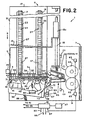
- Figure 2 is an enlarged to plan view of Figure 1;
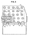
- Figure 3 is an enlarged detailed view of the nudger wall of Figure 1;
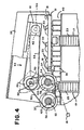
- Figure 4 is an enlarged top plan view partially in section along line IV-IV of Figure 3 showing details of the nudger roller drive system;
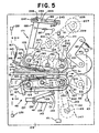
- Figure 5 is an enlarged detailed top plan view of the separator of Figure 1;
- Figure 6 is an end view taken along line VI ― VI of Figure 5;
- Figure 7 is a cross-section of the driven pulley of the feed assembly;
- Figure 8 is a cross-section of the idler pulley of the feed assembly; and
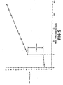
- Figure 9 is a force versus mailpiece thickness graph.
- Referring to Figs. 1 and 2, a mixed
mail feeder 1 is shown. Mixedmail feeder 1, as will be discussed in more detail below, separatesindividual mailpieces 3 from a stack of mixed mail generally designated at 5 and transports theindividual mailpieces 3 to a subsequentmail processing station 7.Mail processing station 7 can be any one of a plurality of devices such as a meter for printing postage on themailpiece 3, an OCR reader for reading addresses off of themailpiece 3, a sorting device for sorting theindividual mailpieces 3 to designated bins or areas, or even a scale that weighs the mailpiece. The key point is that the mixedmail feeder 1 functions to separateindividual mailpieces 3 from a stack of mixedmail 5 and deliver theindividual mailpieces 3 sequentially to themail processing station 7. - Mixed
mail feeder 1 includes a table 9 upon which all of the components of the mixedmail feeder 1 are mounted. At an input end of the mixedmail feeder 1, generally designated by thearrow 11, the stack of mixedmail 5 is placed on edge by an operator in front of aguide wall 13.Guide wall 13 acts as a support against which the stack of mixedmail 5 rests. Moreover,guide wall 13 includes a cylindrical portion 13a which is mounted to slide on aguide rod 15 fixedly attached toplatform 10 which is mounted to table 9. -
Platform 10 has first andsecond slots horizontal surface 21 thereof. Theslots continuous belt Belts individual track portions 27 over the full extent of thebelts guide wall 13 removably fits inadjacent track portions 27 of each ofbelts guide wall 13 moves withbelts guide wall 13 moves in the direction of arrow A with thebelts guide rod 15 to keep the standing orientation ofguide wall 13 in the position shown in Fig. 1. -
Continuous belts motor 29. Themotor 29 drives a common shaft (not shown) connected to the drive pulleys of each of thebelts belts belts guide wall 13 moves therewith so that the entire stack of mixedmail 5 is moved toward anudger wall 31. As will be discussed in more detail below, the stack of mixedmail 5 will haveindividual mailpieces 3 moved from the stack downstream so that the stack of mixed mailpieces is continuously reduced in size. When theguide wall 13 has been moved to a point where it is desirable to add additional pieces of mixed mail to the stack, theguide wall 13 can be lifted out of theindividual tracks 27 of thebelts guide wall 13 up to rotate, via the cylindrical portion 13a, about theguide rod 15. Once the bottom of theguide wall 13 is clear of theindividual tracks 27 of thebelts - Referring to Figure 1, 2, and 3,
nudger wall 31 includes a plurality ofrollers 33 mounted therein in a conventional manner to be freely rotatable. Furthermore,nudger wall 31 has acutout 35 in a lower corner thereof through which drivennudger rollers 37 project. Moreover, a plurality of roller bars 38 are rotatably mounted in a conventional manner in aslot 40 ofplatform 10. Thus, asguide wall 13 pushes the stack ofmixed mail 5 towardnudger wall 31, individual pieces ofmail 3 fall off the end ofbelts rollers 38 and into contact with thenudger rollers 37. While in the preferred embodiment the roller bars 38 are not driven, they could be driven to provide additional forward feed force to themailpiece 3. In one embodiment, a continuous belt (not shown) is driven around the roller bars 38. The use of the continuous belt provides a greater coefficient of friction as compared to the roller bars and thus improves the feed force and provides for a simple drive structure. - The
nudger rollers 37 are mounted to be driven into rotation within anudger arm 39. The fournudger rollers 37 are driven together by amotor 41, mounted onnudger arm 39, via adrive train 43 as shown schematically in Figure 2 and in detail in Figure 4. As shown in Figures 2 and 4, all of thenudger rollers 37 are driven into rotation in a clockwise direction. Accordingly, as the stack ofmixed mail 5 is moved towardnudger wall 31, thelead mailpiece 3a is forced into contact with thenudger rollers 37. The force of the drivennudger rollers 37 acts against thelead mailpiece 3a to move themailpiece 3a in the direction of aseparator device 45, thereby shingling thelead mailpiece 3a from the stack ofmixed mail 5 as shown in Figures 1 and 2. The shingled stack is then transported to the nip 46 ofseparator 45 which separates thelead mailpiece 3a from the shingled stack and delivers it to take-awayrollers 65 which transport theindividual lead mailpiece 3a further downstream tomail processing station 7. - Referring to Figures 3 and 4, the details of the
drive system 43 are shown.Motor 41 has a shaft 41 a connected to apulley 42. Acontinuous belt 44 is disposed aroundpulley 42 and asecond pulley 46.Pulley 46 is fixedly mounted to arotatable shaft 48 mounted innudger arm 39. Also, fixedly mounted toshaft 48 is athird pulley 50.Additional shafts nudger arm 39 and respectively have fourth andfifth pulleys Nudger rollers 37 are mounted on a corresponding one ofshafts motor 41 rotatespulley 42 in the clockwise direction of Fig. 4,pulley 46 andhub 48 are drive in the clockwise direction as well. Since acontinuous belt 60 passes around pulleys 48, 56, and 58,shafts nudger rollers 37. - In order for the
nudger rollers 37 to effectively feed the stack of mixed mail into theseparator 45, accurate control of the normal force applied to the stack ofmixed mail 5 by the interaction of theguide wall 13 and thenudger rollers 37 needs to be achieved. The normal force is created by aspring 49 that is fixedly mounted at one end to thenudger wall 31 and at its other end to a mountingplatform 50 ofnudger arm 39. Thenudger arm 39 is pivotally mounted about aconventional pivot structure 51 so that thespring 49 biases thenudger rollers 37 through thecutout 35 and into contact with thelead mailpiece 3a. Thus, as theguide wall 13 is advanced in the direction of thenudger wall 31, thenudger arm 39 is forced to rotate in the clockwise direction of Figure 2 aroundpivot structure 51 in opposition to the biasing force of thespring 49. As thespring 49 is extended due to the rotation ofnudger arm 39 about thepivot structure 51, the force exerted by thespring 49 is continually increased. - As discussed above, it is desirable to regulate the amount of normal force being exerted by the
spring 49, via thenudger rollers 37, on the stack ofmixed mailpieces 5 to ensure that only the minimal amount of normal force required to permit thenudger rollers 37 to move each of themixed mailpieces 3 toward theseparator 45 is applied. That is, it is not desirable to continuously runmotor 29 to constantly advance theguide wall 13 toward thenudger wall 31. If this occurs,spring 49 will be extended to a length that applies too great a normal force on thelead mailpiece 3a. While this greater normal force may be acceptable for feedingheavier mailpieces 3 toward theseparator 45, it can create a significant problem for very thin mailpieces and untabbed mailpieces. That is, as the thin and untabbed mailpieces are fed by thenudger rollers 37 into,theseparator 45, they can easily be buckled and damaged due to the feeding force of thenudger rollers 37 and the forces exerted byseparator 45. Additionally, if theguide wall 13 is advanced too far toward thenudger wall 31 the stack ofmixed mail 5 will be clamped in place preventing the feeding of individual mailpieces fromstack 5. To preventthis from happening, the contact point of thenudger rollers 37 against thelead mailpiece 3a is always maintained closer to thestack 5 than the facing surface of thenudger wall 31 is to thestack 5. This is accomplished by ensuring that the rotation ofarm 39 is controlled (as discussed in more detail below) so that the contact point of thenudger rollers 37 against the mailpieces occurs between 7 to 16 millimeters away from guide wall 31 (contact point ofrollers 37 extends beyondwall 31 in this range). This configuration permits theguide wall 31 to provide support to large mailpieces while at the same time it does not provide a surface at which the mailpieces can be clamped in place. Correspondingly, if theguide wall 13 is not advanced sufficiently enough towardnudger wall 31, thespring 49 will only be extended to provide a very small normal stack force. If this force is too small, the action of the driven rotatingnudger rollers 37 on thelead mailpiece 3a will be insufficient to overcome the inter-document forces existing between individual pieces of the stack ofmixed mail 5 such that the shingling of themailpieces 3 and the advancement of the shingled stack towardseparator 45 will not occur and a stalled condition atnudger wall 31 occurs. Thus, as described above, the normal force which is created by the positioning of themailpiece stack 5 against thenudger rollers 37 and the corresponding force created by the extension ofspring 49 needs to be maintained in an approximate range of 1-2 newtons in orderto ensure that the various types ofmixed mailpieces 3 which may be processed are properly shingled and fed vertically into the throat ofseparator 45 without being damaged or stalled atnudger wall 31. - Since the normal force is provided by the extension of
spring 49, it can be controlled by accurately regulating the position ofnudger arm 39 which correspondingly regulates the extension ofspring 49. That is, since the normal force applied byspring 49 is directly proportional to its extension, the normal force that it applies to the stack ofmixed mail 5 is controlled by regulating the extension ofspring 49. - The aforementioned control of the extension of
spring 49 and rotation ofnudger arm 39 is accomplished via the utilization of conventional through-beam sensors finger 59 which projects fromnudger arm 39. Asnudger arm 39 rotates aboutpivot structure 51, thefinger 59 will move between the threesensors finger 59 blocks an individual one of the through-beam sensors mail feeder microprocessor 61 indicating the position of thefinger 59 at the blocked sensor. The known position of thefinger 59 corresponds to a known position of thenudger arm 39 and a known amount of extension of thespring 49. Thus, at any of the positions where thefinger 59 blocks one of thesensors spring 49 through thenudger rollers 37 on the stack ofmail 5 is known. - . If the
finger 59 is blocking the beam of thefirst sensor 53, themicroprocessor 61 knows that thenudger rollers 37 are at their innermost position relative to the stack ofmixed mail 5. At this position, the normal force exerted byspring 49 is below the desired minimum value of I newton and must be increased. The increase in normal force is created when themicroprocessor 61, in response to a signal fromsensor 53, energizes themotor 29 to move thebelts guide wall 13 advances themixed mail stack 5 into thenudger rollers 37. Themotor 29 will advance the stack ofmixed mail 5 until thenudger arm 39 pivots aboutpivot structure 51 to the position wherefinger 59 blocks the through-beam sensor 55. When this occurs, thesensor 55 sends a signal tomicroprocessor 61 which in turn deenergizes motor 29 stopping the advance of the stack ofmixed mail 5 toward thenudger rollers 37. In this position, thenudger rollers 37 are considered to be in the "out" position where the maximum desired normal force is being exerted on thelead mailpiece 3a due to the extension of thespring 49. Subsequently, as mail is fed from the stack ofmixed mail 5 toward theseparator 45 due to the action of therotating nudger rollers 37, thenudger rollers 37 gradually move toward the innermost normal force position. When thenudger arm 39 has rotated inwardly such that thenudger rollers 37 are in the innermost normal force position,microprocessor 61 receives a signal fromsensor 53 and energizesmotor 29 to advance the stack ofmail 5 until thesecond sensor 55 is blocked by thefinger 59. In this manner, constant regulation of the normal force in the predetermined range is maintained. - In a first preferred embodiment, the automatic control of the normal force, as described above, would only use the
sensors 53 and 55 to ensure that the normal force generated by thenudger rollers 37 stays within the predetermined desired normal force range. However, in a second preferred embodiment, a second tier of additional stack force can be applied if it is determined that amailpiece 3 has stalled at thenudger rollers 37 or at theseparator 45. That is, it is possible, since themixed mail feeder 1 is designed to handle many different types of mixed mail, that a very heavy piece of mail may have stalled (become stuck) at thenudger rollers 37 orseparator 45. This situation would occur when the normal force applied by thenudger rollers 37 is insufficient to shingle the heavier mailpieces from the stack ofmixed mail 5 and move the shingled stack downstream into the nip of theseparator 45. If stalling occurs, themixed mail feeder 1 is essentially in a jammed or inoperative position. The way in which themixed mail feeder 1 determines that a stall has occurred is by the use of a through-beam sensor 63, which is positioned proximate to the nip oftakeaway rollers 65.Takeaway rollers 65, in a conventional manner, receive individual mailpieces fromseparator 45 and move theindividual mailpieces 3 downstream. Thus, if thetakeaway rollers 65 feed a first mailpiece and do not process asecond mailpiece 3 downstream in a predetermined period of time of, for example, 1,000 msec, the through-beam ofsensor 63 does not detect the lead edge of the second mailpiece during that same predetermined time period. If themicroprocessor 61 does not receive an indication from thesensor 63 that a leading edge of the second mailpiece has passed thereby within the predetermine period of time,microprocessor 61 is programmed to assume that a stall has occurred somewhere upstream.Microprocessor 61 then energizesmotor 29 to cause the stack ofmixed mail 5 to be moved toward thenudger wall 31. Thenudger arm 39 Is forced rotate about thepivot point 51 and thespring 49 is further extended.Motor 29 is driven until nudgerarm 39 is advanced to block thethird sensor 57. In this position, a stalled normal force, which is larger than the maximum normal force applied under normal operating conditions, is being exerted on thelead mailpiece 3a by thenudger rollers 37 and themotor 29 is rendered inoperative bymicroprocessor 61. The increased normal force can simply be due to the further extension of thespring 49 as thenudger arm 39 is rotated from itsposition blocking sensor 55 to itsposition blocking sensor 57, or can be further increased by the force of anadditional compression spring 66 which only contacts thenudger arm 39 to provide an additional spring force thereto when thenudger arm 39 moves beyond the position from the blocking ofsensor 55 toward the blocking ofsensor 57. Assuming that the additional normal force applied is sufficient to move the stalledmailpiece 3, thetakeaway sensor 63 will provide an input to themicroprocessor 61 identifying that the lead edge of the stalled mailpiece has passed thereby and the processing ofindividual mailpieces 3 will continue by driving thenudger rollers 37 until thenudger arm 39 moves to a position where thefirst sensor 53 is blocked byfinger 59. At this position, the system will operate as discussed above, regulating a force profile by maintaining the position ofnudger arm 39 between thesensors nudger arm 39 to block thesensor 57 does not correct the stalled problem, themicroprocessor 61, after a predetermined period of time, will provide an input to the user via adisplay 67 identifying the stalled condition and advising that operator intervention is required to correct the problem. As is readily apparent to one skilled in the art, themicroprocessor 61 controls all of the motors typically associated with the stack advance, shingling device, separator, and take away rollers and includes known clock structure for determining the predetermined time periods discussed above. Empirical testing has shown that for the anticipated mixed mailpiece profile the additional normal force applied during movement offinger 59 fromsensor 55 tosensor 57 goes from 2 to 5 newtons. - In yet another embodiment of the invention, a different mechanism is used to provide additional force in the situation where stalled mail is detected. That is, once the
microprocessor 61 determines that a stall has occurred, utilization of asolenoid 71 and anotherspring 73 provides additional normal force in an attempt to overcome the stalled situation. Thesolenoid 71 is fixedly mounted to theplatform 9 and thespring 73 has one end fixedly mounted to thenudger arm 39 and a second end fixedly mounted to amoveable plunger 75 ofsolenoid 71. When thenudger arm 39 is positioned in the normal force operating range, thespring 73 is slack, thereby providing no additional normal spring force. However, when stalled mail is detected, themicroprocessor 61 energizes thesolenoid 71 to withdraw theplunger 75 such that thespring 73 is extended to provide an additional normal force to themixed mail stack 5 via thenudger rollers 37. The force applied by the solenoid/spring combination 71/73 can be consistently applied for a predetermined period of time or can be pulsed to help the stalled mail break away. Moreover, in a more complex arrangement, different levels of force can be applied by thespring 73 andsolenoid 71 combination over a predetermined time period in an attempt to break the stalled mailpiece away. The gradual application of increased forces has the benefit of not immediately providing too great a force to the stalled mailpiece, which force could potentially damage the piece of mail if it is too great. The advantages of using the solenoid/spring 71/73 combination is that, unlike the previously described embodiments, the application of the additional force does not depend on the stack advance response time such that the stalled mail situation is corrected faster thereby improving the overall throughput of the mixed mail feeder. Additionally, the use of the solenoid/spring 71/73 combination reduces the range ofnudger roller 37 motion, thereby "aiming" the mail at the feeder closer to the optimum area. Finally, while Figure 2 shows each of thesprings - Referring to figures 5 and 6,
separator 45 includes areverse belt assembly 105 and afeed belt assembly 107.Feed belt assembly 107 is fixedly mounted to afeed deck 109.Shafts feed deck 109 andend plate 117.Clips 119 retainshafts end plate 117 while shaft 111 is mounted for rotation therein.Pulley assemblies shafts pulley 121 and the idler pulleys 123/125. As shown, each of the idler pulley assemblies 123/125 is mounted onball bearings 235 about theirrespective shafts 113/115. Drivenpulley assembly 121 is also mounted onball bearings 235 but is also mounted on an overrunningclutch 233 for purposes to be discussed later. Eachpulley assembly 121/123/125 has three serrated, crownedhub portions 126 around which a respective one of each of threecontinuous belts 127 is disposed. Moreover, abracket 129 has afree end 131 at which aroller 133 is mounted for rotation and asecond end 135 which is pivotably mounted to abracket 137 which itself is fixedly mounted to feeddeck 109. Aspring 139 has afirst end 141 connected to thesecond end 135 ofbracket 129 and asecond end 143 fixedly mounted within the mail handling machine.Spring 139biases roller 133 intobelt 127 to maintain a proper belt tension. As shown in Figure 6, there is atension roller 133 for eachbelt 127. - The
feed belt assembly 107 is driven by amotor 147 which is controlled bymicroprocessor 61. Ashaft 149 is driven bymotor 147 and in turn drives apulley 151 which is fixedly mounted toshaft 149. Acontinuous belt 153 is disposed aroundpulley 151 and also around apulley 155 fixedly mounted to a lower portion of shaft 111 which extends belowdeck 109. Thus, asmotor 147 rotatesshaft 149 in the clockwise direction of Figure 5,pulley 151,pulley 155, shaft 111, andpulley assembly 121 also rotate in the clockwise direction. The clockwise rotation ofpulley assembly 121 causesbelts 127 to move in the clockwise direction with idler pulley assemblies 123/125, thereby feeding thelead mailpiece 3a toward the take awayrollers 65. -
Feed belt assembly 107 also includes aguide 157 fixedly attached to feeddeck 109.Guide 157 includes 4fingers 159 which extend on either side of the threefeed belts 127. As themailpieces 3 are moved in the direction of arrow "A" by the nudger system (represented schematically as 161 in Figure 5) theguide 157 prevents the mailpieces from hitting and getting caught on the threebelts 127 and guides themailpieces 3 toward separator nip 46. This prevents themailpieces 3 from being routed behindfeed belt apparatus 107. -
Reverse belt assembly 105 includes a mailpieceingestion guide plate 163 that is pivotably mounted to feeddeck 109 and biased towardmailpieces 3 byspring 165.Spring 165 is connected to apost 167 fixed tobase 109.Ingestion guide 163 is mounted on and pivots about ashaft 169 which itself is fixedly mounted at one end infeed deck 109. Thus, asmailpieces 3 enter nip 46, theingestion guide 163 via itsoutboard fingers 173 contacts and applies a normal force to thelead mailpiece 3a.Middle finger 176 prevents mail from curling up between the reverse beltassembly retard belts 175. It is important to note that the positioning of thebiased ingestion guide 163 within nip 46 helps to solve two fundamental problems associated with the separation and feeding of mixed mail. Firstly, if some of themailpieces 3 are a very thin material it is possible that when theseparator 45 acts to separate thelead mailpiece 3a from the shingled stack ofmailpieces 3, thethin mailpieces 3 buckle in nip 46 instead of being separated and fed toward the take awayrollers 65. The presence of thebiased ingestion guide 163 helps to stabilize thin mailpieces thereby reducing significantly the buckling problem discussed above and preventing damage to thin mailpieces. Secondly, in orderto further prevent the curl up situation from occurring a through-beam sensor 101 is located just upstream fromnip 46. The sensor provides an indication tomicroprocessor 61 as to whether amailpiece 3 is present. If no mailpiece is sensed as beingpresent microprocessor 61 operates thenudger rollers 37 to continue feedingmailpieces 3 toward thenip 46. However, ifsensor 101 senses the presence of amailpiece 3,microprocessor 61 stops the feeding of mailpieces bynudger rollers 37. Since the mailpieces are only being acted upon by theseparator 45 and not thenudger rollers 37, it is less likely that thin mailpieces will curl up in the nip. However when thenudger rollers 37 are stopped, the sensed mailpiece has not been fully ingested innip 46 and it is possible that in some instances thefeed belts 127 will not be able to move thelead mailpiece 3a into nip 46 such that a stall occurs. This situation might occur when a glossy piece of mail with a low coefficient of friction is present or even when a thickermailpiece is present. Thebiased ingestion guide 163 provides a normal force against themailpiece 3a which increases the feed force of thefeed belts 127 to help prevent the stalled mail situation. Thirdly, theingestion guide 163 assists in the feeding of short mailpieces which leave thenudger rollers 37 before being fully ingested in to nip 46. Furthermore, it is to be noted that initially the Applicants usedfingers fingers sensor 101 does not detect the presence of amailpiece 3 within a predetermined time period of, for example, 1,000 msec, the microprocessor assumes a stall has occurred upstream and causes thenudger rollers 37 to feed mailpieces toward nip 46 while concurrently increasing the normal stack force as described above in connection with take awaysensor 63. -
Main bracket assembly 171 includes atop bracket portion 177 and abottom bracket portion 179 which are interconnected via anintermediate bracket portion 181.Main bracket assembly 171 is mounted to be freely rotatably around adrive shaft 183. Furthermore, extending fromintermediate bracket portion 181 is alever arm 185.Lever arm 185 is connected to afirst spring 187 and asecond spring 189. Each ofsprings main bracket assembly 171 toward themailpieces 3 as will be discussed in more detail below. - Fixedly mounted on
shaft 183 is apulley assembly 190 having two crowned hub portions (not shown but similar to the pulley/hub configuration of Figure 7) around whichbelts 175 are disposed. Also fixedly mounted onshaft 183 is asecond pulley 193. Additionally, asecond shaft 195 is fixedly mounted at each end inbrackets third shaft 199 is also fixedly mounted betweenend brackets belts 175 are each disposed around a respective hub of each of thepulley assemblies 190, 197,201. Additionally, aroller 178 is mounted for rotation onpulley 190.Roller 178 rides on themiddle feed belt 127 when no mail is present. - In operation,
shaft 183 is driven into rotation in the clockwise direction of Figure 5 causing thepulley assembly 190 to rotate therewith which in turn causes thebelts 175 to move around theidler pulley assemblies lead mailpiece 3a and thenext mailpiece 3b enter thenip 46, feedbelts 127 drive thelead mailpiece 3a toward the take awayrollers 65 while the opposite rotation of the reversebelt assembly belts 175 separates thesecond mailpiece 3b from thelead mailpiece 3a so that only asingle mailpiece 3a is removed by the take awayrollers 65 and processed further downstream. That is, the feeding force of thefeed belts 127 is greater than the reverse drive force of thereverse belts 175 which is greater than the inter-document forces. Thus, the force of thefeed belts 127 and thereverse belts 175 overcome the inter-document forces to shear the mailpieces away from each other. - Drive
shaft 183 is driven into rotation as follows. Amotor 205 is fixedly mounted belowfeed deck 109.Motor 205 drives ashaft 207 into clockwise rotation which causes apulley 209 attached to theshaft 207 to rotate in that same direction. Acontinuous belt 211 is disposed aroundpulley 209 and anotherpulley 212.Pulley 212 is fixedly connected to ashaft 213 upon which anotherpulley 215 is fixedly connected. Thus, as theshaft 207 is forced to rotate, all of the pulleys, 209 212, and 215 are forced to rotate in the clockwise direction. A secondcontinuous belt 217 is disposed aroundpulley 215,pulley 193 and apulley 219 associated with take awayrollers 65. Thus, themotor 205 which is controlled bymicroprocessor 61 not only drives theshaft 183 in the clockwise direction but at the same time theshaft 221 around which the take awayroller pulley 219 is mounted is driven In the clockwise direction. Thus, asingle motor 205 drives theretard assembly belts 175 to separate the mailpieces as well as the take awayrollers 65 for accelerating and feeding thelead mailpiece 3a downstream. However, as previously discussed, thefeed assembly belts 127 are driven by aseparate motor 147. - The reason for driving the
feed belt assembly 107 with a different motor than both thereverse belt assembly 105 and the take awayrollers 65 is to prevent a problem which can occur in known singulating apparatus where the take away rollers, the reverse belt assembly, and the feed belt assembly are all driven by a single motor. That is, in the situation where a single motor is used the entire singulating assembly may fall to separate thesecond mailpiece 3b from the lead themailpiece 3a such that two mailpieces in overlapping relationship to each other (known as a "double") are passed out of the singulator assembly and fed into the take awayrollers 65. In this situation it is often the case that the take away rollers may continue to feed the double mailpiece structure. Since the purpose of the singulating apparatus is to ensure that only individual pieces of mail are processed downstream, this is an undesirable situation. By utilizing two separate motors the possibility of a double feed is greatly reduced. That is, in the inventive apparatus when the lead edge of thelead mallpiece 3a is detected by thesensor 63, themicroprocessor 61 will stop themotor 147 from driving the feedbelt assembly belts 127. Thus, even if a double feed is present it will not continue to be driven by thefeed belts 127 toward the take awayrollers 65. Rather, the take awayroller 65 will pull thelead mailpiece 3a while thebelts 175 of thereverse belt assembly 105 are still driven to separate thesecond mailpiece 3b away from thelead mailpiece 3a. Thus, the capability of the singulating apparatus to ensure that doubles are not feed to the take awayroller 65 is effectively enhanced. Moreover, when thesensor 63 detects the trail edge of thelead mailpiece 3a, thefeed roller belts 127 are once again driven to separate
Claims (10)
- A singulator for use in apparatus having means (37) for moving articles of mixed sizes from a stack of articles of mixed sizes along a feed path, the singulator (45) comprising:a feed deck (109);forwardly driving means (107), connected to the feed deck (109), for contacting successive articles (3) along a first surface thereof and for advancing the articles in a first direction along the feed path and over the feed deck (109); anda reverse driving mechanism (105), connected to the feed deck (109), for contacting the articles along a second surface thereof and for applying driving force to the articles in a second direction opposite to the first direction whereby only one (3a) of the articles at a time is moved by the forwardly driving means (107) in the first direction along the feed path and over the feed deck (109), the forwardly driving means (107) and the reverse driving mechanism (105) being connected to the feed deck (109) relative to each other to define a nip (46) for ingestion of articles therebetween;characterized by:means (101) located just upstream from the nip (46) for sensing if at least one of the articles is present in the nip (46); andcontrol means (61), operatively connected to the sensing means (101), for operating the moving means (37) to move articles from the stack toward the nip (46) at times when the sensing means (101) does not sense the presence of the at least one of the articles in the nip and for preventing the moving means (37) from moving articles from the stack toward the nip (46) at times when the sensing means (101) senses the presence of the at least one of the articles in the nip (46).
- A singulator as recited in Claim 1, wherein:the moving means (37) applies an article ingestion force to the articles within a predetermined force range to move the articles toward the feed nip (46); andthe control means (61) including means for determining if the sensing means (101) does not detect the presence of the at least one of the articles within a predetermined time period and for causing the moving means (37) to apply a feed force to the articles which is greater than any force value within the predetermined force range if the presence of the at least one of the articles is not sensed by the sensor means (101) in the predetermined time period.
- A singulator as recited in Claim 2, further comprising an ingestion guide (163) extending into the nip (46), means (165) for biasing the ingestion guide (163) into contact with the second surface of the articles so that the ingestion guide (163) provides stability to the articles thereby preventing them from curling up in the nip (46) due to the action of the reverse driving mechanism (105) and provides a normal force to the articles thereby increasing the feeding force applied by the forwardly driving means (107) to the first surface.
- A singulator as recited in Claim 3, wherein the ingestion guide (163) includes a stainless steel surface which contacts the second surface.
- A singulator as recited in Claim 4, further comprising take away means (65) for accelerating the articles in the first direction away from the forwardly driving means, and wherein the forwardly driving means (107) includes a first motor (147) and a plurality of feed belts (127) which contact the first surface and are driven into rotation by the first motor (147) to move the articles in the first direction, the reverse driving mechanism includes a second motor (205) and a plurality of reverse belts (175) which contact the second surface and are driven into rotation by the second motor (205) to apply driving force to the articles in the second direction, and the take away means includes the second motor (205).
- A singulator as recited in Claim 5, further comprising take away sensing means (63), operatively connected to the control means (61), for sensing when articles are present at the take away means (65), and wherein at times when the take away sensing means senses the presence of articles the control means (61) stops operation of the first motor (147) thereby stopping rotation of the forwardly driving means to permit the take away means to accelerate articles from the nip (46) without damage to the articles.
- A singulator as recited in Claim 6, wherein the forwardly driving means includes a drive shaft (111) connected to the first motor (147), an overrunning clutch (233) fixedly mounted to the drive shaft, and a pulley assembly (126) mounted on the overrunning clutch (233) and around which the plurality of feed belts (127) are disposed, and wherein at times when the first motor (147) drives the drive shaft (111) the pulley assembly (126) is driven via the overriding clutch (233) to drive the plurality of feed belts (127) into rotation and at times when the first motor (147) is not energized the pulley assembly (126) is free to rotate around the drive shaft (111) as the take away means accelerate the articles out of the nip (46) and away from the forwardly driving means.
- A singulator as recited in Claim 1, further comprising first spring means (187) for biasing the reverse driving mechanism (105) into contact with the second surface to apply a first normal force thereto within a predetermined first force range and second spring means (189) for biasing the reverse driving mechanism (105) into contact with the second surface to apply a second normal force in addition to the first normal force to the second surface upon the occurrence of a predetermined condition.
- A singulator as recited in Claim 8, wherein the predetermined condition occurs when a mailpiece of a predetermined thickness enters the nip and the second normal force applied is approximately 6 newtons.
- A method for separating articles of mixed sizes from a stack of articles of mixed sizes being moved along a feed path, the method comprising the steps of:utilizing a feed mechanism (37) to feed articles of mixed sizes along the feed path;causing a forward drive mechanism (107) to contact successive articles along a first surface thereof for moving the articles in a first direction along the feed path; andengaging a reverse driving mechanism (105) with the articles along a second surface thereof for applying driving force to the articles in a second direction opposite to the first direction whereby only one of the articles at a time is moved by the forwardly drive means (107) in the first direction along the feed path, the forward drive mechanism (107) and the reverse driving mechanism (105) being positioned relative to each other to define a nip (46) for ingesting articles therebetween;characterized by:sensing by means (101) located just upstream from the nip (46) if at least one of the articles is present in the nip (46);operating the feeding mechanism (37) for feeding articles from the stack toward the nip (46) at times when the presence of the at least one of the articles in the nip is not sensed; andpreventing the feeding mechanism (37) from feeding articles from the stack toward the nip at times when the sensing means senses the presence of the at least one of the articles in the nip (46).
Applications Claiming Priority (2)
| Application Number | Priority Date | Filing Date | Title |
|---|---|---|---|
| US08/943,407 US6003857A (en) | 1997-10-03 | 1997-10-03 | Singulating apparatus for a mail handling system |
| US943407 | 1997-10-03 |
Publications (3)
| Publication Number | Publication Date |
|---|---|
| EP0906881A1 EP0906881A1 (en) | 1999-04-07 |
| EP0906881B1 EP0906881B1 (en) | 2002-09-04 |
| EP0906881B2 true EP0906881B2 (en) | 2006-08-23 |
Family
ID=25479608
Family Applications (1)
| Application Number | Title | Priority Date | Filing Date |
|---|---|---|---|
| EP98118650A Expired - Lifetime EP0906881B2 (en) | 1997-10-03 | 1998-10-02 | Singulating apparatus for a mail handling system |
Country Status (4)
| Country | Link |
|---|---|
| US (1) | US6003857A (en) |
| EP (1) | EP0906881B2 (en) |
| CA (1) | CA2249284C (en) |
| DE (1) | DE69807616T3 (en) |
Families Citing this family (39)
| Publication number | Priority date | Publication date | Assignee | Title |
|---|---|---|---|---|
| US6354583B1 (en) | 1999-01-25 | 2002-03-12 | Bell & Howell Mail And Messaging Technologies Company | Sheet feeder apparatus and method with throughput control |
| US6276679B1 (en) * | 1999-11-23 | 2001-08-21 | Pitney Bowes Inc. | Floating idler pulley retard system for mixed mail separation |
| JP3372925B2 (en) * | 2000-03-21 | 2003-02-04 | 日本電気株式会社 | Postal information input device and its data display method |
| US6897394B1 (en) * | 2000-04-04 | 2005-05-24 | Opex Corporation | System and method for automated document processing |
| US6629018B2 (en) | 2000-04-28 | 2003-09-30 | Rapistan Systems Advertising Corp. | Selective advance intelligent singulator |
| US6585251B2 (en) | 2001-11-13 | 2003-07-01 | Pitney Bowes Inc. | Articulating separator |
| US6988021B2 (en) | 2001-12-19 | 2006-01-17 | Pitney Bowes Inc. | Method of addressing and sorting an interoffice distribution using an incoming mail sorting apparatus |
| FR2833934B1 (en) * | 2001-12-24 | 2004-07-09 | Neopost Ind | MAIL ARTICLE SELECTOR DEVICE |
| US6905661B2 (en) | 2001-12-31 | 2005-06-14 | Pitney Bowes Inc. | System for sanitizing and sorting mail |
| US20030124039A1 (en) * | 2001-12-31 | 2003-07-03 | Ryan William E. | System for sanitizing incoming mail |
| US7071437B2 (en) | 2001-12-31 | 2006-07-04 | Pitney Bowes Inc. | System for detecting the presence of harmful materials in an incoming mail stream |
| US6740836B2 (en) | 2001-12-31 | 2004-05-25 | Pitney Bowes Inc. | System and method for outsorting suspect mail from an incoming mail stream |
| DE10203951A1 (en) * | 2002-02-01 | 2003-08-14 | Pitney Bowes Technologies Gmbh | Mail processing system |
| US7165053B2 (en) * | 2002-06-13 | 2007-01-16 | Pitney Bowes Inc. | System and method for pre-feeding mailpieces, detecting the presence of harmful materials in the mailpieces and sorting the mailpieces |
| US6886419B2 (en) * | 2002-06-20 | 2005-05-03 | Pitney Bowes Inc. | Mail piece for obtaining samples of harmful materials in mail processing equipment |
| US6781078B2 (en) | 2002-06-28 | 2004-08-24 | Pitney Bowes Inc. | System and method for identifying potentially life harming mailpieces in an incoming mail stream |
| DE60320572T2 (en) * | 2002-10-29 | 2009-06-04 | Siemens Aktiengesellschaft | CONVEYOR DEVICE HANDLING THE DISTRIBUTED ARTICLE |
| DE10350623B3 (en) * | 2003-10-30 | 2005-04-14 | Siemens Ag | Mail item separation device has transport section between mail stack input region and at least one separation region with coordinated control of conveyor drives for transport stage and separation stage |
| US7303188B2 (en) * | 2003-11-06 | 2007-12-04 | James Malatesta | Document separator |
| DE10356364B4 (en) * | 2003-11-28 | 2010-04-15 | Deutsche Post Ag | Substance input device for the further transport of mail |
| DE102004037420B3 (en) * | 2004-07-30 | 2005-12-15 | Siemens Ag | Device for extracting individual flat items from a separating line |
| DE102005012029B3 (en) * | 2005-03-16 | 2006-07-13 | Siemens Ag | Device for separating overlapping surface transmissions |
| FR2906235B1 (en) * | 2006-09-21 | 2009-05-29 | Solystic Sas | DEVICE FOR DEPILING POSTAL SHIPMENTS WITH OPTIMIZED MANAGEMENT OF DEPILING CONDITIONS |
| US7806398B2 (en) * | 2007-10-03 | 2010-10-05 | Pitney Bowes Inc. | Ingestion guide assembly for augmenting sheet material separation in a singulating apparatus |
| US7934719B2 (en) * | 2007-12-05 | 2011-05-03 | Burroughs Payment Systems, Inc. | Document feeder flag assembly |
| US8016282B2 (en) * | 2007-12-21 | 2011-09-13 | Pitney Bowes Inc. | Transport for singulating items |
| FR2940259A1 (en) * | 2008-12-19 | 2010-06-25 | Neopost Technologies | IMPROVED FEEDING DEVICE IN MAIL ARTICLES |
| JP2010208800A (en) * | 2009-03-10 | 2010-09-24 | Toshiba Corp | Paper feeder |
| DE102009039066A1 (en) * | 2009-08-27 | 2011-03-10 | Siemens Aktiengesellschaft | Device and method for separating flat objects with compensation of wear |
| JP5578878B2 (en) * | 2010-02-24 | 2014-08-27 | キヤノン株式会社 | Feed separation device and recording device |
| FR2957906B1 (en) * | 2010-03-25 | 2012-05-18 | Solystic | FEEDING DEVICE FOR POSTAL SHIPMENTS WITH A SEPARATE STORE AND DEPILEOR |
| PL2560906T3 (en) | 2010-04-19 | 2019-07-31 | Opex Corporation | Feeder for feeding document to document imaging system |
| JP2014141341A (en) * | 2013-01-25 | 2014-08-07 | Riso Kagaku Corp | Printer |
| US9376275B2 (en) | 2013-03-12 | 2016-06-28 | United States Postal Service | Article feeder with a retractable product guide |
| US9044783B2 (en) | 2013-03-12 | 2015-06-02 | The United States Postal Service | System and method of unloading a container of items |
| US9061849B2 (en) | 2013-03-14 | 2015-06-23 | United States Postal Service | System and method of article feeder operation |
| US9056738B2 (en) | 2013-03-13 | 2015-06-16 | United States Postal Service | Anti-rotation device and method of use |
| US9340377B2 (en) | 2013-03-12 | 2016-05-17 | United States Postal Service | System and method of automatic feeder stack management |
| DE102015006667A1 (en) | 2015-05-22 | 2016-11-24 | Giesecke & Devrient Gmbh | Device for processing sheet material |
Citations (2)
| Publication number | Priority date | Publication date | Assignee | Title |
|---|---|---|---|---|
| US3988017A (en) † | 1975-03-20 | 1976-10-26 | Lockheed Electronics Co., Inc. | Workpiece feeding device |
| US4030722A (en) † | 1975-05-13 | 1977-06-21 | Pitney-Bowes, Inc. | Sheet-material separator and feeder system |
Family Cites Families (8)
| Publication number | Priority date | Publication date | Assignee | Title |
|---|---|---|---|---|
| US4893804A (en) * | 1987-07-01 | 1990-01-16 | Nec Corporation | Apparatus for feeding sheet articles |
| DE3833506A1 (en) * | 1988-10-01 | 1990-04-05 | Didier Werke Ag | DEVICE FOR INJECTING A REPAIR SIZE ONTO A HOLE STONE |
| US4909499A (en) * | 1988-12-28 | 1990-03-20 | Pitney Bowes Inc. | Mail singulating apparatus |
| US4978114A (en) * | 1989-11-14 | 1990-12-18 | Pitney Bowes Inc. | Reverse belt singulating apparatus |
| US5074540A (en) * | 1990-11-05 | 1991-12-24 | Pitney Bowes Inc. | Document singulating apparatus |
| US5238236A (en) * | 1992-11-12 | 1993-08-24 | Pitney Bowes Inc. | Document singulating apparatus for feeding upright documents of varying thickness |
| JP3205624B2 (en) * | 1992-12-28 | 2001-09-04 | キヤノン株式会社 | Paper feeder |
| US5431385A (en) * | 1994-03-03 | 1995-07-11 | Pitney Bowes Inc. | Ingestion roller for mixed mail feeder |
-
1997
- 1997-10-03 US US08/943,407 patent/US6003857A/en not_active Expired - Lifetime
-
1998
- 1998-10-01 CA CA002249284A patent/CA2249284C/en not_active Expired - Fee Related
- 1998-10-02 EP EP98118650A patent/EP0906881B2/en not_active Expired - Lifetime
- 1998-10-02 DE DE69807616T patent/DE69807616T3/en not_active Expired - Lifetime
Patent Citations (2)
| Publication number | Priority date | Publication date | Assignee | Title |
|---|---|---|---|---|
| US3988017A (en) † | 1975-03-20 | 1976-10-26 | Lockheed Electronics Co., Inc. | Workpiece feeding device |
| US4030722A (en) † | 1975-05-13 | 1977-06-21 | Pitney-Bowes, Inc. | Sheet-material separator and feeder system |
Also Published As
| Publication number | Publication date |
|---|---|
| US6003857A (en) | 1999-12-21 |
| DE69807616T3 (en) | 2007-03-08 |
| CA2249284A1 (en) | 1999-04-03 |
| CA2249284C (en) | 2002-09-03 |
| EP0906881B1 (en) | 2002-09-04 |
| DE69807616D1 (en) | 2002-10-10 |
| EP0906881A1 (en) | 1999-04-07 |
| DE69807616T2 (en) | 2003-08-07 |
Similar Documents
| Publication | Publication Date | Title |
|---|---|---|
| EP0906881B2 (en) | Singulating apparatus for a mail handling system | |
| EP0906880B1 (en) | A nudger for a mail handling system | |
| US6270070B1 (en) | Apparatus and method for detecting and correcting high stack forces | |
| EP1111547B1 (en) | Apparatus for detecting proper mailpiece position for feeding | |
| EP0926085B1 (en) | Dual document singulating apparatus for a mail handling system | |
| CA2322065C (en) | Aligner mechanism for a mail handling system | |
| US6550764B2 (en) | Apparatus and method for controlling a document-handling machine | |
| EP0660797B1 (en) | Pre-feed shingling device for flat-article feeder | |
| US5033729A (en) | Mechanism for the handling and singulating of flat materials | |
| US5769408A (en) | Apparatus for feeding sheets | |
| AU2009288641B2 (en) | Envelope conveying and positioning apparatus and related methods | |
| US5257777A (en) | Belt separator for document singulation | |
| US5265731A (en) | Job separator | |
| AU2009288642B2 (en) | Inserting apparatus for discrete objects into envelopes and related methods | |
| US5409204A (en) | Singulator assembly having a buffer with a biased arm | |
| US5456457A (en) | High speed separator with movable hold back belt for high speed flats feeder | |
| US4548393A (en) | Inserter feeder document stop | |
| US5217218A (en) | Dual auger stacking device and control therefor | |
| US20010035602A1 (en) | Mail piece feeder for vertically orientated mail pieces and having reversible retard rollers | |
| AU639932B2 (en) | Single sheet picking and transport mechanism | |
| EP0537978B1 (en) | Method and apparatus for sorting cut sheet form components into stacks | |
| JPH05178471A (en) | Sheet feeding device | |
| US20100156027A1 (en) | Item feeder with overthickness detection | |
| EP0852563A1 (en) | Separator with hold back belt for feeder |
Legal Events
| Date | Code | Title | Description |
|---|---|---|---|
| PUAI | Public reference made under article 153(3) epc to a published international application that has entered the european phase |
Free format text: ORIGINAL CODE: 0009012 |
|
| AK | Designated contracting states |
Kind code of ref document: A1 Designated state(s): DE FR GB |
|
| AX | Request for extension of the european patent |
Free format text: AL;LT;LV;MK;RO;SI |
|
| 17P | Request for examination filed |
Effective date: 19990715 |
|
| AKX | Designation fees paid |
Free format text: DE FR GB |
|
| 17Q | First examination report despatched |
Effective date: 20010209 |
|
| GRAG | Despatch of communication of intention to grant |
Free format text: ORIGINAL CODE: EPIDOS AGRA |
|
| GRAG | Despatch of communication of intention to grant |
Free format text: ORIGINAL CODE: EPIDOS AGRA |
|
| GRAH | Despatch of communication of intention to grant a patent |
Free format text: ORIGINAL CODE: EPIDOS IGRA |
|
| GRAH | Despatch of communication of intention to grant a patent |
Free format text: ORIGINAL CODE: EPIDOS IGRA |
|
| GRAA | (expected) grant |
Free format text: ORIGINAL CODE: 0009210 |
|
| AK | Designated contracting states |
Kind code of ref document: B1 Designated state(s): DE FR GB |
|
| REG | Reference to a national code |
Ref country code: GB Ref legal event code: FG4D |
|
| REF | Corresponds to: |
Ref document number: 69807616 Country of ref document: DE Date of ref document: 20021010 |
|
| ET | Fr: translation filed | ||
| PLBQ | Unpublished change to opponent data |
Free format text: ORIGINAL CODE: EPIDOS OPPO |
|
| PLBI | Opposition filed |
Free format text: ORIGINAL CODE: 0009260 |
|
| PLAX | Notice of opposition and request to file observation + time limit sent |
Free format text: ORIGINAL CODE: EPIDOSNOBS2 |
|
| 26 | Opposition filed |
Opponent name: FRANCOTYP-POSTALIA AKTIENGESELLSCHAFT & CO. KG Effective date: 20030523 |
|
| PLAX | Notice of opposition and request to file observation + time limit sent |
Free format text: ORIGINAL CODE: EPIDOSNOBS2 |
|
| PLBB | Reply of patent proprietor to notice(s) of opposition received |
Free format text: ORIGINAL CODE: EPIDOSNOBS3 |
|
| PLCK | Communication despatched that opposition was rejected |
Free format text: ORIGINAL CODE: EPIDOSNREJ1 |
|
| APBP | Date of receipt of notice of appeal recorded |
Free format text: ORIGINAL CODE: EPIDOSNNOA2O |
|
| APBQ | Date of receipt of statement of grounds of appeal recorded |
Free format text: ORIGINAL CODE: EPIDOSNNOA3O |
|
| PLAQ | Examination of admissibility of opposition: information related to despatch of communication + time limit deleted |
Free format text: ORIGINAL CODE: EPIDOSDOPE2 |
|
| PLAR | Examination of admissibility of opposition: information related to receipt of reply deleted |
Free format text: ORIGINAL CODE: EPIDOSDOPE4 |
|
| PLBQ | Unpublished change to opponent data |
Free format text: ORIGINAL CODE: EPIDOS OPPO |
|
| PLAB | Opposition data, opponent's data or that of the opponent's representative modified |
Free format text: ORIGINAL CODE: 0009299OPPO |
|
| R26 | Opposition filed (corrected) |
Opponent name: FRANCOTYP-POSTALIA AKTIENGESELLSCHAFT & CO. KG Effective date: 20030523 |
|
| APAH | Appeal reference modified |
Free format text: ORIGINAL CODE: EPIDOSCREFNO |
|
| APBU | Appeal procedure closed |
Free format text: ORIGINAL CODE: EPIDOSNNOA9O |
|
| PUAH | Patent maintained in amended form |
Free format text: ORIGINAL CODE: 0009272 |
|
| STAA | Information on the status of an ep patent application or granted ep patent |
Free format text: STATUS: PATENT MAINTAINED AS AMENDED |
|
| 27A | Patent maintained in amended form |
Effective date: 20060823 |
|
| AK | Designated contracting states |
Kind code of ref document: B2 Designated state(s): DE FR GB |
|
| ET3 | Fr: translation filed ** decision concerning opposition | ||
| PGFP | Annual fee paid to national office [announced via postgrant information from national office to epo] |
Ref country code: DE Payment date: 20091028 Year of fee payment: 12 |
|
| REG | Reference to a national code |
Ref country code: DE Ref legal event code: R119 Ref document number: 69807616 Country of ref document: DE Effective date: 20110502 |
|
| PGFP | Annual fee paid to national office [announced via postgrant information from national office to epo] |
Ref country code: FR Payment date: 20111028 Year of fee payment: 14 |
|
| PG25 | Lapsed in a contracting state [announced via postgrant information from national office to epo] |
Ref country code: DE Free format text: LAPSE BECAUSE OF NON-PAYMENT OF DUE FEES Effective date: 20110502 |
|
| REG | Reference to a national code |
Ref country code: FR Ref legal event code: ST Effective date: 20130628 |
|
| PG25 | Lapsed in a contracting state [announced via postgrant information from national office to epo] |
Ref country code: FR Free format text: LAPSE BECAUSE OF NON-PAYMENT OF DUE FEES Effective date: 20121031 |
|
| PGFP | Annual fee paid to national office [announced via postgrant information from national office to epo] |
Ref country code: GB Payment date: 20161027 Year of fee payment: 19 |
|
| GBPC | Gb: european patent ceased through non-payment of renewal fee |
Effective date: 20171002 |
|
| PG25 | Lapsed in a contracting state [announced via postgrant information from national office to epo] |
Ref country code: GB Free format text: LAPSE BECAUSE OF NON-PAYMENT OF DUE FEES Effective date: 20171002 |