EP0905418A2 - Shift method for semi-automatic motor vehicle transmission - Google Patents
Shift method for semi-automatic motor vehicle transmission Download PDFInfo
- Publication number
- EP0905418A2 EP0905418A2 EP98113383A EP98113383A EP0905418A2 EP 0905418 A2 EP0905418 A2 EP 0905418A2 EP 98113383 A EP98113383 A EP 98113383A EP 98113383 A EP98113383 A EP 98113383A EP 0905418 A2 EP0905418 A2 EP 0905418A2
- Authority
- EP
- European Patent Office
- Prior art keywords
- transmission
- electronics
- synchronization process
- time
- driver
- Prior art date
- Legal status (The legal status is an assumption and is not a legal conclusion. Google has not performed a legal analysis and makes no representation as to the accuracy of the status listed.)
- Granted
Links
Images

Classifications
-
- F—MECHANICAL ENGINEERING; LIGHTING; HEATING; WEAPONS; BLASTING
- F16—ENGINEERING ELEMENTS AND UNITS; GENERAL MEASURES FOR PRODUCING AND MAINTAINING EFFECTIVE FUNCTIONING OF MACHINES OR INSTALLATIONS; THERMAL INSULATION IN GENERAL
- F16H—GEARING
- F16H61/00—Control functions within control units of change-speed- or reversing-gearings for conveying rotary motion ; Control of exclusively fluid gearing, friction gearing, gearings with endless flexible members or other particular types of gearing
- F16H61/04—Smoothing ratio shift
- F16H61/08—Timing control
-
- F—MECHANICAL ENGINEERING; LIGHTING; HEATING; WEAPONS; BLASTING
- F16—ENGINEERING ELEMENTS AND UNITS; GENERAL MEASURES FOR PRODUCING AND MAINTAINING EFFECTIVE FUNCTIONING OF MACHINES OR INSTALLATIONS; THERMAL INSULATION IN GENERAL
- F16H—GEARING
- F16H61/00—Control functions within control units of change-speed- or reversing-gearings for conveying rotary motion ; Control of exclusively fluid gearing, friction gearing, gearings with endless flexible members or other particular types of gearing
- F16H61/02—Control functions within control units of change-speed- or reversing-gearings for conveying rotary motion ; Control of exclusively fluid gearing, friction gearing, gearings with endless flexible members or other particular types of gearing characterised by the signals used
- F16H61/0202—Control functions within control units of change-speed- or reversing-gearings for conveying rotary motion ; Control of exclusively fluid gearing, friction gearing, gearings with endless flexible members or other particular types of gearing characterised by the signals used the signals being electric
- F16H61/0248—Control units where shifting is directly initiated by the driver, e.g. semi-automatic transmissions
-
- F—MECHANICAL ENGINEERING; LIGHTING; HEATING; WEAPONS; BLASTING
- F16—ENGINEERING ELEMENTS AND UNITS; GENERAL MEASURES FOR PRODUCING AND MAINTAINING EFFECTIVE FUNCTIONING OF MACHINES OR INSTALLATIONS; THERMAL INSULATION IN GENERAL
- F16H—GEARING
- F16H59/00—Control inputs to control units of change-speed-, or reversing-gearings for conveying rotary motion
- F16H59/36—Inputs being a function of speed
- F16H59/46—Inputs being a function of speed dependent on a comparison between speeds
- F16H2059/462—Detecting synchronisation, i.e. speed difference is approaching zero
-
- F—MECHANICAL ENGINEERING; LIGHTING; HEATING; WEAPONS; BLASTING
- F16—ENGINEERING ELEMENTS AND UNITS; GENERAL MEASURES FOR PRODUCING AND MAINTAINING EFFECTIVE FUNCTIONING OF MACHINES OR INSTALLATIONS; THERMAL INSULATION IN GENERAL
- F16H—GEARING
- F16H59/00—Control inputs to control units of change-speed-, or reversing-gearings for conveying rotary motion
- F16H59/68—Inputs being a function of gearing status
- F16H2059/6807—Status of gear-change operation, e.g. clutch fully engaged
-
- Y—GENERAL TAGGING OF NEW TECHNOLOGICAL DEVELOPMENTS; GENERAL TAGGING OF CROSS-SECTIONAL TECHNOLOGIES SPANNING OVER SEVERAL SECTIONS OF THE IPC; TECHNICAL SUBJECTS COVERED BY FORMER USPC CROSS-REFERENCE ART COLLECTIONS [XRACs] AND DIGESTS
- Y10—TECHNICAL SUBJECTS COVERED BY FORMER USPC
- Y10S—TECHNICAL SUBJECTS COVERED BY FORMER USPC CROSS-REFERENCE ART COLLECTIONS [XRACs] AND DIGESTS
- Y10S477/00—Interrelated power delivery controls, including engine control
- Y10S477/906—Means detecting or ameliorating the effects of malfunction or potential malfunction
- Y10S477/907—Redundant
-
- Y—GENERAL TAGGING OF NEW TECHNOLOGICAL DEVELOPMENTS; GENERAL TAGGING OF CROSS-SECTIONAL TECHNOLOGIES SPANNING OVER SEVERAL SECTIONS OF THE IPC; TECHNICAL SUBJECTS COVERED BY FORMER USPC CROSS-REFERENCE ART COLLECTIONS [XRACs] AND DIGESTS
- Y10—TECHNICAL SUBJECTS COVERED BY FORMER USPC
- Y10S—TECHNICAL SUBJECTS COVERED BY FORMER USPC CROSS-REFERENCE ART COLLECTIONS [XRACs] AND DIGESTS
- Y10S477/00—Interrelated power delivery controls, including engine control
- Y10S477/908—In series transmission
Definitions
- the invention relates to a method for switching a semi-automatic, electronically controlled Gearbox for motor vehicles according to the preamble of Claim 1.
- Such transmissions are referred to as semi-automatic, where another clutch with a clutch pedal is present, which the driver during a shift must be operated. It is common with such Geared that a gear indicator is provided on which is an inserted one calculated by switching electronics Gear is displayed. If the driver does wants to put in a new gear, he operates the lever of one Switching command, which the switching request to the Electronics forwards. The switching electronics calculated a cheap gear that flashes on the gear indicator is shown. At the same time, the driver needs the clutch disconnect by pressing the clutch pedal. Through the above Electronics then generally Valves connected to a pressure medium supply are connected, and the corresponding cylinder Shift shift sleeves in the gearbox so that the desired up or down shift is carried out becomes.
- the Feedback device can be optical, acoustic or be haptic.
- From DE 30 07 953 A1 is a gear shift for a known gear operated with external power.
- This one has a shift command transmitter, the lever of which by the driver can first be pushed into a locked position. This initiates the gear shift.
- the gear lever from the Locked position released using a locking pin and can then be pivoted further into an end position become.
- haptic feedback of the gear change is the driver without distraction by optical or acoustic signals that he is now the Can re-insert the clutch.
- a switching device is also known from DE-33 29 802 C2 for a synchronized transmission, in which the movement of the sliding sleeves or with them connected actuating cylinders or linkages by means of Is recorded.
- the disadvantage of the known arrangements is the relative long total time required for gear shifting because this is the driver's reaction time of different lengths for reinserting the clutch.
- the invention is based on the object of a method for switching a semi-automatic motor vehicle transmission indicate which is a shortening of the Total switching time and thus that during the switching occurring power flow interruption enables.
- the invention enables the total switching time to significantly shorten a gear shift, and to make the driver less reactive.
- the feedback signal not only when the gear is shifted, but earlier, when synchronization started, submitted.
- the resulting shortening of the power flow interruption has a special effect on the vehicle cheap when driving on a slope or on an incline off because here is the speed of the vehicle changes less during the break.
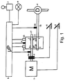
- FIG. 1 is a schematic block diagram of the entire drive train of a motor vehicle with one auxiliary operated, electronically controlled transmission (3).
- a motor M (1) On a motor M (1) is one Disc clutch (2) connected, which with a Input shaft (17) of the transmission (3) is connected.
- the Input shaft (17) drives in a known manner over several, constantly engaged gears one Transmission output shaft (18). This is a common one Differential D (4) connected.
- the gears of the input shaft (17) can be adjusted via sliding sleeves (15, 16) can be coupled with this as desired.
- Actuators (12, 13) are used for this purpose Solenoid valves and working cylinders exist. Through the mentioned solenoid valves can be a pressure medium that comes from a storage container (not shown), Use to move the sliding sleeves (15, 16). As a pressure medium such. B. compressed air can be used.
- the motor (1) can be operated by the driver via an accelerator pedal (5), and the clutch (2) is controlled via a clutch pedal (6) become.
- the driver can choose gears operate a switching command transmitter (7).
- One with this preselected gear is electronics (8), which contains a microprocessor control ( ⁇ P).
- the electronics (8) then control the corresponding ones Actuators (12, 13) for changing gear on.
- the displacement of the sliding sleeves (15, 16) sensed by displacement sensors (14) and the electronics (8) reported back.
- the speed also continues the transmission input shaft (17) via a speed sensor (10, 11) communicated to the electronics (8).
- Another Speed sensor (20) detects the speed of the transmission output shaft (18).
- a Feedback signal passed to a feedback device (9). As shown, this can be optical, but also be acoustic or haptic. The driver recognizes from the activated feedback device (9), that the internal gear change in the transmission (3) is completed and can then release the clutch (2) close the clutch pedal (6) again.
- the electronics (8) of the gear change control are universal can be used for gearboxes (3) of various types is in a known manner during the first start-up or also during operation, the position signals the displacement sensor (14) within the electronics (8) calibrated by program using teach-in processes.
- the diagram in FIG. 2 shows an example of a shift process, namely from neutral to fourth gear, over time (t).
- the vehicle was previously in third gear.
- the speed (N E ) of the transmission input shaft drops due to the changeover to a lower value.
- the vehicle speed (not shown) remains approximately constant during the switching operation.
- the path (S) of the sliding sleeve (15 or 16) initially increases at the beginning of the circuit (t 1 ) until a grinding position is reached at time t 2 and the actual synchronization process begins. From this point on, the route (S) hardly changes. The synchronization is completed shortly before time t 3 . Now the speeds of the transmission input shaft and gear of the new gear have adjusted. The input shaft and the gear can now be positively connected by means of a pawl. This can be seen from a further increase in the path (S) of the sliding sleeve (15 or 16) shortly before the time t 3 .
- the electronics (8) expediently continuously evaluate a number of travel values to increase the security against errors, namely approximately 10 values of the travel sensors (14) of the synchronization device.
- the oldest value is omitted and the newest value is added.
- the position of the position sensors is sensed in time by the electronics in a 5 ms grid. For safety reasons, an averaging of the evaluated distance values takes place. This mean is now compared with the next mean, and a gradient is formed. The beginning of the synchronization process at time t 2 is recognized from the gradient of the averaged distance values.
- the feedback device (9) is already activated by the electronics (8) when the above-mentioned gradient of the averaged path values falls below a predetermined threshold, ie when the path (S) only increases at a certain, low speed. This is the case shortly after time t 2 .
- the feedback device (9) is then expediently activated only after a time T 3 delayed after the time t 2 at a time t 2 '(see FIG. 2).
- the delay time T 3 is dimensioned such that the sum of T 2 and T 3 is in any case behind the time t 3 .
- the displacement sensors (14) for detecting the displacement of the Sliding sleeves (15, 16) can be in different places to be appropriate. So the ways of the sleeves can directly can be evaluated, but also the ways of Actuators (pistons of the working cylinders) be sensed in the actuating elements (12, 13). The displacement sensors can also be used on the connecting rods to be appropriate.
- the start of the synchronization process may alternatively also be detected from the change in the rotational speed (N E) of the transmission input shaft (17).
- N E rotational speed of the gearbox input shaft at the time t 2
- a distinct kink This can be evaluated in the same way as described above for the sliding sleeve path.
- the two signs of the start of the synchronization namely the path of the sliding sleeves (15, 16) and the kink of the input speed ( NE ) of the transmission input shaft (17), can expediently also be evaluated in combination by the electronics (8).
- T 1 is typically around 500 ms. If the expected respective duration of the gear shift has been calculated shortly after the break point of N E (time t 2 ), the time t 2 'for actuating the signal generator (9) can be set even more precisely so that after the typical, smallest response time t 2 of the driver of 300 ms, the changeover in the transmission has already been completed (time t 3 ).
Landscapes
- Engineering & Computer Science (AREA)
- General Engineering & Computer Science (AREA)
- Mechanical Engineering (AREA)
- Control Of Transmission Device (AREA)
- Mechanical Operated Clutches (AREA)
Abstract
Description
Die Erfindung bezieht sich auf ein Verfahren zum Schalten eines halbautomatischen, elektronisch gesteuerten Getriebes für Kraftfahrzeuge gemäß dem Oberbegriff des Patentanspruchs 1.The invention relates to a method for switching a semi-automatic, electronically controlled Gearbox for motor vehicles according to the preamble of Claim 1.
Als halbautomatisch werden solche Getriebe bezeichnet, bei denen noch eine Kupplung mit einem Kupplungspedal vorhanden ist, welches vom Fahrer während eines Schaltvorganges betätigt werden muß. Üblich ist bei derartigen Getrieben, daß eine Ganganzeige vorgesehen ist, auf welcher ein von einer Schaltelektronik berechneter eingelegter Gang angezeigt wird. Falls der Fahrer einen neuen Gang einlegen möchte, betätigt er den Hebel eines Schaltbefehlsgebers, welcher den Schaltwunsch an die Elektronik weiterleitet. Die Schaltelektronik berechnet einen günstigen Gang, der auf der Ganganzeige blinkend angezeigt wird. Gleichzeitig muß der Fahrer die Kupplung durch Betätigung des Kupplungspedals auftrennen. Durch die o. g. Elektronik werden dann im allgemeinen Ventile geschaltet, welche an einen Druckmittelvorrat angeschlossen sind, und über Arbeitszylinder die entsprechenden Schaltmuffen im Getriebe so verschieben, daß die gewünschte Rauf- oder Runterschaltung ausgeführt wird.Such transmissions are referred to as semi-automatic, where another clutch with a clutch pedal is present, which the driver during a shift must be operated. It is common with such Geared that a gear indicator is provided on which is an inserted one calculated by switching electronics Gear is displayed. If the driver does wants to put in a new gear, he operates the lever of one Switching command, which the switching request to the Electronics forwards. The switching electronics calculated a cheap gear that flashes on the gear indicator is shown. At the same time, the driver needs the clutch disconnect by pressing the clutch pedal. Through the above Electronics then generally Valves connected to a pressure medium supply are connected, and the corresponding cylinder Shift shift sleeves in the gearbox so that the desired up or down shift is carried out becomes.
Sobald dieser Schaltvorgang beendet ist, wird durch die Elektronik eine Rückmeldeeinrichtung angesteuert, durch welche der Fahrer auf die im Getriebe vollzogene Umschaltung aufmerksam gemacht wird. Hieraufhin muß der Fahrer die Kupplung über das Kupplungspedal wieder einkuppeln. Die Rückmeldeeinrichtung kann optisch, akustisch oder haptisch ausgebildet sein.As soon as this switching process is completed, the Electronics controlled by a feedback device which of the driver on the changeover carried out in the transmission attention is drawn. Then the Driver engage the clutch again using the clutch pedal. The feedback device can be optical, acoustic or be haptic.
Aus der DE 30 07 953 A1 ist eine Gangschaltung für ein mit Fremdkraft betätigtes Getriebe bekannt. Dieses hat einen Schaltbefehlsgeber, dessen Hebel durch den Fahrer zunächst in eine Sperrposition geschoben werden kann. Hierdurch wird die Gangumschaltung eingeleitet. Sobald diese vollendet ist, wird der Schalthebel aus der Sperrposition mittels eines Sperrstiftes freigegeben und kann dann weiter bis in eine Endposition geschwenkt werden. Durch diese "haptische" Rückmeldung der Gangumschaltung wird dem Fahrer ohne Ablenkung durch optische oder akustische Signale mitgeteilt, daß er nun die Kupplung wieder einlegen kann.From DE 30 07 953 A1 is a gear shift for a known gear operated with external power. This one has a shift command transmitter, the lever of which by the driver can first be pushed into a locked position. This initiates the gear shift. As soon as this is completed, the gear lever from the Locked position released using a locking pin and can then be pivoted further into an end position become. Through this "haptic" feedback of the gear change is the driver without distraction by optical or acoustic signals that he is now the Can re-insert the clutch.
Bekannt ist weiter aus der DE-33 29 802 C2 eine Schaltvorrichtung für ein synchronisiertes Getriebe, bei welchem die Bewegung der Schiebemuffen bzw. der mit diesen verbundenen Betätigungszylindern bzw. Gestängen mittels Weggebern erfaßt wird.A switching device is also known from DE-33 29 802 C2 for a synchronized transmission, in which the movement of the sliding sleeves or with them connected actuating cylinders or linkages by means of Is recorded.
Nachteilig an den bekannten Anordnungen ist die relativ lange für die Gangschaltung benötigte Gesamtzeit, da diese die unterschiedlich lange Reaktionszeit des Fahrers für das Wiedereinlegen der Kupplung mit einschließt.The disadvantage of the known arrangements is the relative long total time required for gear shifting because this is the driver's reaction time of different lengths for reinserting the clutch.
Der Erfindung liegt nun die Aufgabe zugrunde, ein Verfahren zum Schalten eines halbautomatischen Kraftfahrzeug-Getriebes anzugeben, welches eine Verkürzung der Gesamt-Schaltzeit und damit der während der Schaltung auftretenden Kraftflußunterbrechung ermöglicht.The invention is based on the object of a method for switching a semi-automatic motor vehicle transmission indicate which is a shortening of the Total switching time and thus that during the switching occurring power flow interruption enables.
Diese Aufgabe wird durch die im Patentanspruch 1 enthaltene Erfindung gelöst. Die Unteransprüche enthalten zweckmäßige Weiterbildungen.This object is achieved by the contained in claim 1 Invention solved. The sub-claims included appropriate training.
Durch die Erfindung ist es möglich, die Gesamtschaltdauer einer Gangumschaltung erheblich zu verkürzen, und vom Reaktionsvermögen des Fahrers unabhängiger zu machen. Im Gegensatz zum Stand der Technik wird das Rückmeldesignal nicht erst bei vollzogener Gangumschaltung, sondern schon früher, bei Beginn der Synchronisierung, abgegeben. Die hierdurch bewirkte Verkürzung der Kraftfluß-Unterbrechung beim Fahrzeug wirkt sich besonders bei Fahrten im Gefälle oder in einer Steigung günstig aus, da sich hier die Geschwindigkeit des Fahrzeuges während der Schaltpause weniger ändert.The invention enables the total switching time to significantly shorten a gear shift, and to make the driver less reactive. In contrast to the prior art, the feedback signal not only when the gear is shifted, but earlier, when synchronization started, submitted. The resulting shortening of the power flow interruption has a special effect on the vehicle cheap when driving on a slope or on an incline off because here is the speed of the vehicle changes less during the break.
Die Erfindung wird im folgenden anhand einer Zeichnung näher erläutert. Diese zeigt in
- Fig. 1
- ein schematisches Blockschaltbild des Antriebsstranges eines KFZ mit einem elektronisch gesteuerten hilfskraftbetätigten Getriebe, und in
- Fig. 2
- ein Diagramm der Eingangswellendrehzahl (NE) des Getriebes sowie des Weges (S) einer Schiebemuffe der Synchronisiereinrichtung über der Zeit (t) während eines Schaltvorganges.
- Fig. 1
- is a schematic block diagram of the drive train of a motor vehicle with an electronically controlled auxiliary power transmission, and in
- Fig. 2
- a diagram of the input shaft speed (N E ) of the transmission and the path (S) of a sliding sleeve of the synchronizer over time (t) during a switching operation.
In der Fig. 1 ist schematisch das Blockschaltbild des gesamten Antriebsstranges eines Kraftfahrzeuges mit einem hilfskraftbetätigten, elektronisch gesteuerten Getriebe (3) dargestellt. An einen Motor M (1) ist eine Scheibenkupplung (2) angeschlossen, welche mit einer Eingangswelle (17) des Getriebes (3) verbunden ist. Die Eingangswelle (17) treibt in bekannter Weise über mehrere, ständig im Eingriff befindliche Zahnräder eine Getriebeausgangswelle (18) an. Diese ist an ein übliches Differential D (4) angeschlossen.1 is a schematic block diagram of the entire drive train of a motor vehicle with one auxiliary operated, electronically controlled transmission (3). On a motor M (1) is one Disc clutch (2) connected, which with a Input shaft (17) of the transmission (3) is connected. The Input shaft (17) drives in a known manner over several, constantly engaged gears one Transmission output shaft (18). This is a common one Differential D (4) connected.
Die Zahnräder der Eingangswelle (17) können über Schiebemuffen (15, 16) beliebig mit dieser gekuppelt werden. Hierzu dienen Betätigungselemente (12, 13), welche aus Magnetventilen und Arbeitszylindern bestehen. Durch die genannten Magnetventile läßt sich ein Druckmittel, das einem (nicht dargestellten) Vorratsbehälter entstammt, zur Verschiebung der Schiebemuffen (15, 16) ausnutzen. Als Druckmittel kann z. B. Druckluft verwendet werden.The gears of the input shaft (17) can be adjusted via sliding sleeves (15, 16) can be coupled with this as desired. Actuators (12, 13) are used for this purpose Solenoid valves and working cylinders exist. Through the mentioned solenoid valves can be a pressure medium that comes from a storage container (not shown), Use to move the sliding sleeves (15, 16). As a pressure medium such. B. compressed air can be used.
Der Motor (1) kann vom Fahrer über ein Gaspedal (5), und die Kupplung (2) über ein Kupplungspedal (6) gesteuert werden. Zur Auswahl von Gängen kann der Fahrer einen Schaltbefehlsgeber (7) betätigen. Ein mit diesem vorgewählter Gang wird einer Elektronik (8), welche eine Mikroprozessor-Steuerung (µP) enthält, mitgeteilt. Die Elektronik (8) steuert daraufhin die entsprechenden Betätigungselemente (12, 13) zur Umschaltung des Ganges an. Die Verschiebewege der Schiebemuffen (15, 16) werden von Wegsensoren (14) abgefühlt und der Elektronik (8) zurückgemeldet. Weiterhin wird auch die Drehzahl der Getriebeeingangswelle (17) über einen Drehzahlsensor (10, 11) der Elektronik (8) mitgeteilt. Ein weiterer Drehzahlsensor (20) erfaßt die Drehzahl der Getriebeausgangswelle (18).The motor (1) can be operated by the driver via an accelerator pedal (5), and the clutch (2) is controlled via a clutch pedal (6) become. The driver can choose gears operate a switching command transmitter (7). One with this preselected gear is electronics (8), which contains a microprocessor control (µP). The electronics (8) then control the corresponding ones Actuators (12, 13) for changing gear on. The displacement of the sliding sleeves (15, 16) sensed by displacement sensors (14) and the electronics (8) reported back. The speed also continues the transmission input shaft (17) via a speed sensor (10, 11) communicated to the electronics (8). Another Speed sensor (20) detects the speed of the transmission output shaft (18).
Sobald die Elektronik (8) durch die Wegsensoren (14) für die Schiebemuffen (15, 16) sensiert hat, daß die beabsichtigte Gangschaltung vollzogen ist, wird ein Rückmeldesignal auf eine Rückmeldeeinrichtung (9) geleitet. Diese kann, wie dargestellt, optisch, aber auch akustisch oder haptisch ausgebildet sein. Der Fahrer erkennt aus der angesteuerten Rückmeldeeinrichtung (9), daß die interne Gangumschaltung im Getriebe (3) vollzogen ist, und kann daraufhin die Kupplung (2) durch Loslassen des Kupplungspedals (6) wieder schließen.As soon as the electronics (8) through the displacement sensors (14) for the sliding sleeves (15, 16) has sensed that the intended gearshift is completed, a Feedback signal passed to a feedback device (9). As shown, this can be optical, but also be acoustic or haptic. The driver recognizes from the activated feedback device (9), that the internal gear change in the transmission (3) is completed and can then release the clutch (2) close the clutch pedal (6) again.
Damit die Elektronik (8) der Gangumschaltsteuerung universell für Getriebe (3) verschiedener Bauart verwendbar ist, werden in bekannter Weise bei der ersten Betriebnahme oder auch während des Betriebes, die Stellungssignale der Weggeber (14) innerhalb der Elektronik (8) per Programm mittels Einlernvorgängen kalibriert.So that the electronics (8) of the gear change control are universal can be used for gearboxes (3) of various types is in a known manner during the first start-up or also during operation, the position signals the displacement sensor (14) within the electronics (8) calibrated by program using teach-in processes.
Im Diagramm der Fig. 2 ist beispielhaft ein Schaltvorgang, und zwar von Neutral in den vierten Gang, über der Zeit (t) dargestellt. Das Fahrzeug ist vorher im dritten Gang gefahren. Wie man sieht, sinkt die Drehzahl (NE) der Getriebeeingangswelle durch die Umschaltung auf einen niedrigeren Wert ab. Die Fahrzeuggeschwindigkeit (nicht dargestellt) bleibt während der Schalthandlung etwa konstant.The diagram in FIG. 2 shows an example of a shift process, namely from neutral to fourth gear, over time (t). The vehicle was previously in third gear. As you can see, the speed (N E ) of the transmission input shaft drops due to the changeover to a lower value. The vehicle speed (not shown) remains approximately constant during the switching operation.
Der Weg (S) der Schiebemuffe (15 oder 16) steigt zu Beginn der Schaltung (t1) zunächst an, bis im Zeitpunkt t2 eine Schleifstellung erreicht ist, und der eigentliche Synchronisiervorgang beginnt. Ab diesem Zeitpunkt ändert sich der Weg (S) kaum noch. Die Synchronisierung ist kur vor dem Zeitpunkt t3 abgeschlossen. Jetzt haben sich die Drehzahlen von Getriebeeingangswelle und Zahnrad des neuen Ganges angeglichen. Die Eingangswelle und das Zahnrad können jetzt durch eine Sperrklinke formschlüssig verbunden werden. Dies ist erkennbar an einem nochmaligen Anstieg des Weges (S) der Schiebemuffe (15 oder 16) kurz vor dem Zeitpunkt t3.The path (S) of the sliding sleeve (15 or 16) initially increases at the beginning of the circuit (t 1 ) until a grinding position is reached at time t 2 and the actual synchronization process begins. From this point on, the route (S) hardly changes. The synchronization is completed shortly before time t 3 . Now the speeds of the transmission input shaft and gear of the new gear have adjusted. The input shaft and the gear can now be positively connected by means of a pawl. This can be seen from a further increase in the path (S) of the sliding sleeve (15 or 16) shortly before the time t 3 .
Um nun gemäß der Erfindung den gesamten Schaltvorgang zu beschleunigen, wird durch Auswertung des Signals des betreffenden Wegsensors (14) bereits zum Zeitpunkt t2 erkannt, daß die Synchronisierung angefangen hat. Bereits zu diesem Zeitpunkt kann die Rückmeldeeinrichtung (9) angesteuert werden. Hierdurch kann der Fahrer mit dem Wiedereinlegen der Kupplung früher beginnen.In order to accelerate the entire switching process according to the invention, it is already recognized at time t 2 that the synchronization has begun by evaluating the signal of the relevant displacement sensor (14). The feedback device (9) can already be activated at this time. This allows the driver to start reinserting the clutch earlier.
Zweckmäßig wertet die Elektronik (8) zur Erhöhung der Sicherheit gegen Fehler ständig eine Anzahl von Wegwerten, und zwar etwa 10 Werte der Wegsensoren (14) der Synchronisiereinrichtung aus. Dabei wird jeweils der älteste Wert weggelassen und der neueste Wert hinzugenommen. Die zeitliche Abtastung der Stellung der Wegsensoren durch die Elektronik erfolgt zweckmäßig in einem 5 ms-Raster. Zur Sicherheit erfolgt dann eine Mittelwertbildung der ausgewerteten Wegwerte. Dieser Mittelwert wird nun mit dem nächstfolgenden Mittelwert verglichen, und so ein Gradient gebildet. Aus dem Gradienten der gemittelten Wegwerte wird der Beginn des Synchronisierungsvorganges zum Zeitpunkt t2 erkannt. Die Rückmeldeeinrichtung (9) wird von der Elektronik (8) bereits dann angesteuert, wenn der obengenannte Gradient der gemittelten Wegwerte eine festgelegte Schwelle unterschreitet, d. h. wenn sich der Weg (S) nur noch mit einer bestimmten, kleinen Geschwindigkeit erhöht. Dies ist kurz nach dem Zeitpunkt t2 der Fall.The electronics (8) expediently continuously evaluate a number of travel values to increase the security against errors, namely approximately 10 values of the travel sensors (14) of the synchronization device. The oldest value is omitted and the newest value is added. The position of the position sensors is sensed in time by the electronics in a 5 ms grid. For safety reasons, an averaging of the evaluated distance values takes place. This mean is now compared with the next mean, and a gradient is formed. The beginning of the synchronization process at time t 2 is recognized from the gradient of the averaged distance values. The feedback device (9) is already activated by the electronics (8) when the above-mentioned gradient of the averaged path values falls below a predetermined threshold, ie when the path (S) only increases at a certain, low speed. This is the case shortly after time t 2 .
Damit der Fahrer die Kupplung nicht zu früh schließt,
kann zweckmäßig eine minimale Reaktionszeit des Fahrers,
die erfahrungsgemäß etwa T2 = 300 ms beträgt, berücksichtigt
werden. Die Rückmeldeeinrichtung (9) wird
dann also zweckmäßig erst nur einer Zeit T3 verzögert
nach dem Zeitpunkt t2 zu einem Zeitpunkt t2' angesteuert
(s. Fig. 2). Die Verzögerungszeit T3 ist so bemessen,
daß die Summe aus T2 und T3 in jedem Fall hinter
dem Zeitpunkt t3 liegt. Die Zeit T3 läßt sich errechnen
aus
Es hat sich weiter als zweckmäßig herausgestellt, die Länge der Verzögerungszeit T3 von der Getriebetemperatur und/oder der Art des Gangsprunges abhängig zu machen, da diese Daten die Länge T1 einer Gangumschaltung beeinflussen.It has also been found to be expedient to make the length of the delay time T 3 dependent on the transmission temperature and / or the type of gear shift, since these data influence the length T 1 of a gear shift.
Die Wegsensoren (14) zur Erkennung der Verschiebung der Schiebemuffen (15, 16) können an verschiedenen Stellen angebracht sein. So können direkt die Wege der Muffen ausgewertet werden, es können aber auch die Wege der Betätigungseinrichtungen (Kolben der Arbeitszylinder) in den Betätigungselementen (12, 13) abgefühlt werden. Die Wegsensoren können schließlich auch an den Verbindungsgestängen angebracht sein.The displacement sensors (14) for detecting the displacement of the Sliding sleeves (15, 16) can be in different places to be appropriate. So the ways of the sleeves can directly can be evaluated, but also the ways of Actuators (pistons of the working cylinders) be sensed in the actuating elements (12, 13). The displacement sensors can also be used on the connecting rods to be appropriate.
Der Beginn der Synchronisiervorganges kann alternativ auch aus der Änderung der Drehzahl (NE) der Getriebeeingangswelle (17) erkannt werden. Wie aus der Fig. 2 ersichtlich ist, zeigt die Drehzahl (NE) der Getriebeeingangswelle zum Zeitpunkt t2, dem Beginn der Synchronisierung, einen deutlichen Knick. Dieser kann in gleicher Weise, wie oben für den Schiebemuffenweg beschrieben, ausgewertet werden.The start of the synchronization process may alternatively also be detected from the change in the rotational speed (N E) of the transmission input shaft (17). As is apparent from the Fig. 2 indicates the rotational speed (N E) of the gearbox input shaft at the time t 2, the beginning of the synchronization, a distinct kink. This can be evaluated in the same way as described above for the sliding sleeve path.
Die beiden Anzeichen des Beginns der Synchronisierung, nämlich die Wegverläufe der Schiebemuffen (15, 16) sowie der Knick der Eingangsdrehzahl (NE) der Getriebeeingangswelle (17), können zweckmäßigerweise auch kombiniert von der Elektronik (8) ausgewertet werden.The two signs of the start of the synchronization, namely the path of the sliding sleeves (15, 16) and the kink of the input speed ( NE ) of the transmission input shaft (17), can expediently also be evaluated in combination by the electronics (8).
Die voraussichtliche Dauer T1 eines Synchronisiervorganges
kann aus dem Gradienten der Getriebeeingangswellendrehzahl
im Bereich zwischen t2 und t3 schon frühzeitig
berechnet werden. Dies erfolt nach der Formel

Der Wert von T1 beträgt typischerweise etwa 500 ms. Hat man so die voraussichtliche jeweilige Dauer der Gangumschaltung schon kurz nach dem Knickpunkt von NE (Zeitpunkt t2) berechnet, kann man den Zeitpunkt t2' für die Ansteuerung des Signalgebers (9) noch genauer so legen, daß nach Ablauf der typischen, kleinsten Reaktionszeit t2 des Fahrers von 300 ms die Umschaltung im Getriebe bereits vollzogen ist (Zeitpunkt t3).The value of T 1 is typically around 500 ms. If the expected respective duration of the gear shift has been calculated shortly after the break point of N E (time t 2 ), the time t 2 'for actuating the signal generator (9) can be set even more precisely so that after the typical, smallest response time t 2 of the driver of 300 ms, the changeover in the transmission has already been completed (time t 3 ).
Der Zeitpunkt für t2' berechnet sich dann zu
- t2
- = Zeitpunkt des Knickes in NE oder S
- T1
- = Dauer der Synchronisierung
- T2
- = minimale Reaktionszeit des Fahrers.
- t 2
- = Time of the bend in N E or S
- T 1
- = Duration of synchronization
- T 2
- = minimum driver response time.
Claims (16)

- t2
- = Zeitpunkt des Knickes in NE oder S
- T1
- = Dauer des Synchronisiervorganges
- T2
- = minimale Reaktionszeit des Fahrers.
- t 2
- = Time of the bend in N E or S
- T 1
- = Duration of the synchronization process
- T 2
- = minimum driver response time.
Applications Claiming Priority (2)
| Application Number | Priority Date | Filing Date | Title |
|---|---|---|---|
| DE19743180 | 1997-09-30 | ||
| DE19743180A DE19743180A1 (en) | 1997-09-30 | 1997-09-30 | Process for switching a semi-automatic automotive transmission |
Publications (3)
| Publication Number | Publication Date |
|---|---|
| EP0905418A2 true EP0905418A2 (en) | 1999-03-31 |
| EP0905418A3 EP0905418A3 (en) | 2001-05-09 |
| EP0905418B1 EP0905418B1 (en) | 2003-12-17 |
Family
ID=7844141
Family Applications (1)
| Application Number | Title | Priority Date | Filing Date |
|---|---|---|---|
| EP98113383A Expired - Lifetime EP0905418B1 (en) | 1997-09-30 | 1998-07-17 | Electronical control device and shift method for semi-automatic motor vehicle transmission |
Country Status (4)
| Country | Link |
|---|---|
| US (1) | US6567735B1 (en) |
| EP (1) | EP0905418B1 (en) |
| JP (1) | JP4288539B2 (en) |
| DE (2) | DE19743180A1 (en) |
Cited By (2)
| Publication number | Priority date | Publication date | Assignee | Title |
|---|---|---|---|---|
| DE102005018785B4 (en) * | 2004-04-30 | 2008-04-24 | General Motors Corp. (N.D.Ges.D. Staates Delaware), Detroit | Single speed dual speed signal system |
| CN102606726A (en) * | 2012-03-29 | 2012-07-25 | 浙江吉利汽车研究院有限公司 | Neutral gear pre-engaging control device of automobile synchronizer |
Families Citing this family (10)
| Publication number | Priority date | Publication date | Assignee | Title |
|---|---|---|---|---|
| FR2821407A1 (en) * | 2001-02-28 | 2002-08-30 | Luk Lamellen & Kupplungsbau | Drive control for motor vehicle transmission, involves feeding binary signals to control as function of predetermined release |
| US7249193B1 (en) * | 2001-08-28 | 2007-07-24 | Emc Corporation | SRDF assist |
| DE10341621B4 (en) * | 2003-09-10 | 2011-07-07 | Preh GmbH, 97616 | Indicator with a gear indicator |
| KR100672565B1 (en) * | 2004-12-13 | 2007-01-24 | 엘지전자 주식회사 | Apparatus And Method For Notifying Transmision Of Car Gear Using Mobile Phone |
| US7447584B2 (en) * | 2006-01-28 | 2008-11-04 | Mcmullen John William | Gear shift indication method and apparatus |
| US7869924B2 (en) * | 2007-10-10 | 2011-01-11 | GM Global Technology Operations LLC | Method and apparatus to monitor a flow management valve of an electro-mechanical transmission |
| US8255133B2 (en) * | 2009-06-05 | 2012-08-28 | Toyota Motor Engineering & Manufacturing North America, Inc. | Shift timing indicator system for vehicular manual transmission |
| GB2521126A (en) | 2013-12-05 | 2015-06-17 | Tonejet Ltd | Apparatus for controlling ink pressure |
| KR20160047156A (en) | 2014-10-22 | 2016-05-02 | 현대자동차주식회사 | Transmission perception apparatus and method |
| KR102659237B1 (en) * | 2019-05-07 | 2024-04-18 | 현대자동차주식회사 | Method for controlling of electronic clutch apparatus using clutch signal of shift lever |
Citations (3)
| Publication number | Priority date | Publication date | Assignee | Title |
|---|---|---|---|---|
| DE3007953A1 (en) * | 1980-03-01 | 1981-09-17 | Wabco Fahrzeugbremsen Gmbh, 3000 Hannover | GEAR SHIFT FOR A TRANSMISSION ACTUATED BY FOREIGN FORCE |
| DE3822316A1 (en) * | 1987-07-22 | 1989-02-02 | Zahnradfabrik Friedrichshafen | Power-assisted gearshift device |
| JPH07251646A (en) * | 1994-03-17 | 1995-10-03 | Nissan Diesel Motor Co Ltd | Transmission for automobile |
Family Cites Families (21)
| Publication number | Priority date | Publication date | Assignee | Title |
|---|---|---|---|---|
| US4440042A (en) * | 1981-07-29 | 1984-04-03 | Borg-Warner Corporation | Helical planetary gear assembly |
| JPS59156831A (en) * | 1983-02-25 | 1984-09-06 | Toyota Motor Corp | Optimum shift timing display device |
| DE3329802A1 (en) * | 1983-08-18 | 1985-02-28 | Wabco Westinghouse Fahrzeugbremsen GmbH, 3000 Hannover | Synchromesh transmission |
| US4676115A (en) * | 1985-05-13 | 1987-06-30 | Eaton Corporation | Semi-automatic transmission |
| US4711141A (en) * | 1986-04-30 | 1987-12-08 | Eaton Corporation | Method for controlling AMT system including after transmission gear change clutch and fuel control |
| DE3832970C2 (en) * | 1988-09-29 | 1997-09-18 | Porsche Ag | Display device for an automatic motor vehicle transmission |
| US5053962A (en) * | 1989-06-19 | 1991-10-01 | Eaton Corporation | Automatic shift preselection mode for mechanical transmission system with semi-automatic shift implementation |
| US5053961A (en) * | 1989-06-19 | 1991-10-01 | Eaton Corporation | Semi-automatic shift implementation for mechanical transmission system |
| US5167311A (en) * | 1989-09-26 | 1992-12-01 | Zexel Corporation | Transmission control system with gear shift failure detection |
| US4989471A (en) * | 1989-12-01 | 1991-02-05 | Ford New Holland, Inc. | Method of calibrating clutches in transmissions |
| JPH03177656A (en) * | 1989-12-06 | 1991-08-01 | Toyota Motor Corp | Oil pressure control device for automatic transmission |
| JP2827646B2 (en) | 1991-12-28 | 1998-11-25 | トヨタ自動車株式会社 | Speed change instruction device for vehicles |
| FR2708530B1 (en) * | 1993-08-03 | 1997-01-24 | Luk Getriebe Systeme Gmbh | Vehicle fitted with an automatic clutch. |
| JPH07205675A (en) * | 1994-01-26 | 1995-08-08 | Honda Motor Co Ltd | Drive state selection control for vehicle equipped with antilock brake controller |
| DE4424456A1 (en) * | 1994-07-12 | 1996-01-18 | Zahnradfabrik Friedrichshafen | Method for controlling an automatic transmission |
| CN100359213C (en) * | 1994-12-24 | 2008-01-02 | 卢克驱动系统有限公司 | Method for controlling a torque transmission system between driving unit and speed changing gear |
| DE29505468U1 (en) * | 1995-03-29 | 1995-06-01 | Siemens Ag | Device for taking into account the response time of an item of equipment when actuating the item as a function of a travel path |
| DE19531675A1 (en) * | 1995-08-29 | 1997-03-06 | Voith Gmbh J M | Method for operating a vehicle transmission |
| DE19545588A1 (en) * | 1995-12-07 | 1997-06-12 | Zahnradfabrik Friedrichshafen | Temperature monitoring method |
| KR100500721B1 (en) * | 1996-03-14 | 2005-11-25 | 루크 게트리에베시스템 게엠베하 | Vehicle and control method |
| US5771477A (en) * | 1996-05-10 | 1998-06-23 | Borg-Warner Automotive, Inc. | Method and apparatus for synchronizing low to high transfer case shifts |
-
1997
- 1997-09-30 DE DE19743180A patent/DE19743180A1/en not_active Withdrawn
-
1998
- 1998-07-17 DE DE59810445T patent/DE59810445D1/en not_active Expired - Lifetime
- 1998-07-17 EP EP98113383A patent/EP0905418B1/en not_active Expired - Lifetime
- 1998-09-25 JP JP30774598A patent/JP4288539B2/en not_active Expired - Lifetime
- 1998-09-25 US US09/161,146 patent/US6567735B1/en not_active Expired - Lifetime
Patent Citations (3)
| Publication number | Priority date | Publication date | Assignee | Title |
|---|---|---|---|---|
| DE3007953A1 (en) * | 1980-03-01 | 1981-09-17 | Wabco Fahrzeugbremsen Gmbh, 3000 Hannover | GEAR SHIFT FOR A TRANSMISSION ACTUATED BY FOREIGN FORCE |
| DE3822316A1 (en) * | 1987-07-22 | 1989-02-02 | Zahnradfabrik Friedrichshafen | Power-assisted gearshift device |
| JPH07251646A (en) * | 1994-03-17 | 1995-10-03 | Nissan Diesel Motor Co Ltd | Transmission for automobile |
Non-Patent Citations (1)
| Title |
|---|
| PATENT ABSTRACTS OF JAPAN vol. 1996, no. 02, 29. Februar 1996 (1996-02-29) & JP 07 251646 A (NISSAN DIESEL MOTOR CO LTD), 3. Oktober 1995 (1995-10-03) * |
Cited By (3)
| Publication number | Priority date | Publication date | Assignee | Title |
|---|---|---|---|---|
| DE102005018785B4 (en) * | 2004-04-30 | 2008-04-24 | General Motors Corp. (N.D.Ges.D. Staates Delaware), Detroit | Single speed dual speed signal system |
| CN102606726A (en) * | 2012-03-29 | 2012-07-25 | 浙江吉利汽车研究院有限公司 | Neutral gear pre-engaging control device of automobile synchronizer |
| CN102606726B (en) * | 2012-03-29 | 2015-01-07 | 浙江吉利汽车研究院有限公司 | Neutral gear pre-engaging control device of automobile synchronizer |
Also Published As
| Publication number | Publication date |
|---|---|
| JPH11230337A (en) | 1999-08-27 |
| EP0905418A3 (en) | 2001-05-09 |
| EP0905418B1 (en) | 2003-12-17 |
| US6567735B1 (en) | 2003-05-20 |
| DE59810445D1 (en) | 2004-01-29 |
| DE19743180A1 (en) | 1999-04-01 |
| JP4288539B2 (en) | 2009-07-01 |
Similar Documents
| Publication | Publication Date | Title |
|---|---|---|
| DE10308517B4 (en) | Method for coupling characteristic adaptation | |
| EP2376815B1 (en) | Method for the operation of a transmission device of a vehicle drive train | |
| EP0859171B1 (en) | Method for calibrating shifting clutches in a transmission | |
| EP1594715B1 (en) | Method for determining a point of application of the clutch for an automatic gearbox | |
| DE102008043385B4 (en) | Method for determining the synchronization point of an automated dual clutch transmission | |
| EP2417379B1 (en) | Method for operating a transmission with at least one positive-locking shifting element | |
| EP1812735B1 (en) | Method for operating a drive train of a motor vehicle | |
| DE60103803T2 (en) | System and device for switching a servo-assisted manual transmission | |
| DE19829299A1 (en) | Gear change control system for a synchronized transmission | |
| EP3212953B1 (en) | Method for adapting the kiss point of at least one of the clutches of a double clutch of a double clutch transmission of a motor vehicle, in particular the double clutch of an automated double clutch transmission | |
| EP0873902A1 (en) | Method of gear shifting for an unsynchronised gearbox | |
| EP0905418B1 (en) | Electronical control device and shift method for semi-automatic motor vehicle transmission | |
| DE102007019241A1 (en) | Controlling dual clutch transmission involves simultaneously engaging starting gear of one of two driving gears of same stage of transmission to activate parking lock function | |
| DE10305254A1 (en) | Method for controlling and regulating a transmission brake of an automatic transmission designed as a countershaft transmission | |
| DE19953937A1 (en) | Control system for layshaft-type gearbox regulates two gear units, which are arranged in power flow parallel arrangement, each with friction locking load changing clutch | |
| EP1910699B1 (en) | Method and control device for adjusting a speed of a shaft in a gear selector box | |
| EP0599986B1 (en) | Method to engage a reverse drive in a change gear unit | |
| EP1802477B1 (en) | Placing an automatic synchronized transmission into a starting speed | |
| EP1020314B1 (en) | Vehicle propulsion system and method for its control | |
| EP1887261B1 (en) | Method and device for controlling a double-clutch gearbox | |
| DE102004022667B4 (en) | Method for controlling a push downshift | |
| DE19933312A1 (en) | Gearbox control method involves continuous monitoring during gear change of whether desired gear can be engaged taking into account gearbox input and output revolution rates | |
| EP1632694B1 (en) | Power train having a gearbox with two input shafts in parallel | |
| DE10224062C1 (en) | Method of operating automatic gear change for motor vehicle transmission, involves determining neutral drive position for automatic operation of the change selector | |
| DE19652971A1 (en) | Synchronised gearbox for commercial vehicles |
Legal Events
| Date | Code | Title | Description |
|---|---|---|---|
| PUAI | Public reference made under article 153(3) epc to a published international application that has entered the european phase |
Free format text: ORIGINAL CODE: 0009012 |
|
| AK | Designated contracting states |
Kind code of ref document: A2 Designated state(s): DE FR IT SE |
|
| AX | Request for extension of the european patent |
Free format text: AL;LT;LV;MK;RO;SI |
|
| RAP1 | Party data changed (applicant data changed or rights of an application transferred) |
Owner name: WABCO GMBH & CO. OHG |
|
| PUAL | Search report despatched |
Free format text: ORIGINAL CODE: 0009013 |
|
| AK | Designated contracting states |
Kind code of ref document: A3 Designated state(s): AT BE CH CY DE DK ES FI FR GB GR IE IT LI LU MC NL PT SE |
|
| AX | Request for extension of the european patent |
Free format text: AL;LT;LV;MK;RO;SI |
|
| 17P | Request for examination filed |
Effective date: 20011109 |
|
| AKX | Designation fees paid |
Free format text: DE FR IT SE |
|
| RTI1 | Title (correction) |
Free format text: ELECTRONICAL CONTROL DEVICE AND SHIFT METHOD FOR SEMI-AUTOMATIC MOTOR VEHICLE TRANSMISSION |
|
| GRAH | Despatch of communication of intention to grant a patent |
Free format text: ORIGINAL CODE: EPIDOS IGRA |
|
| RTI1 | Title (correction) |
Free format text: ELECTRONICAL CONTROL DEVICE AND SHIFT METHOD FOR SEMI-AUTOMATIC MOTOR VEHICLE TRANSMISSION |
|
| GRAS | Grant fee paid |
Free format text: ORIGINAL CODE: EPIDOSNIGR3 |
|
| GRAA | (expected) grant |
Free format text: ORIGINAL CODE: 0009210 |
|
| AK | Designated contracting states |
Kind code of ref document: B1 Designated state(s): DE FR IT SE |
|
| REG | Reference to a national code |
Ref country code: SE Ref legal event code: TRGR |
|
| REF | Corresponds to: |
Ref document number: 59810445 Country of ref document: DE Date of ref document: 20040129 Kind code of ref document: P |
|
| ET | Fr: translation filed | ||
| PLBE | No opposition filed within time limit |
Free format text: ORIGINAL CODE: 0009261 |
|
| STAA | Information on the status of an ep patent application or granted ep patent |
Free format text: STATUS: NO OPPOSITION FILED WITHIN TIME LIMIT |
|
| 26N | No opposition filed |
Effective date: 20040920 |
|
| REG | Reference to a national code |
Ref country code: FR Ref legal event code: PLFP Year of fee payment: 19 |
|
| REG | Reference to a national code |
Ref country code: FR Ref legal event code: PLFP Year of fee payment: 20 |
|
| PGFP | Annual fee paid to national office [announced via postgrant information from national office to epo] |
Ref country code: FR Payment date: 20170724 Year of fee payment: 20 Ref country code: IT Payment date: 20170706 Year of fee payment: 20 Ref country code: DE Payment date: 20170731 Year of fee payment: 20 |
|
| PGFP | Annual fee paid to national office [announced via postgrant information from national office to epo] |
Ref country code: SE Payment date: 20170717 Year of fee payment: 20 |
|
| REG | Reference to a national code |
Ref country code: DE Ref legal event code: R071 Ref document number: 59810445 Country of ref document: DE |
|
| REG | Reference to a national code |
Ref country code: SE Ref legal event code: EUG |