EP0905032A1 - Blank and container therefrom as well as manufacturing apparatus therefor - Google Patents
Blank and container therefrom as well as manufacturing apparatus therefor Download PDFInfo
- Publication number
- EP0905032A1 EP0905032A1 EP97250261A EP97250261A EP0905032A1 EP 0905032 A1 EP0905032 A1 EP 0905032A1 EP 97250261 A EP97250261 A EP 97250261A EP 97250261 A EP97250261 A EP 97250261A EP 0905032 A1 EP0905032 A1 EP 0905032A1
- Authority
- EP
- European Patent Office
- Prior art keywords
- plate part
- longitudinal
- station
- additional
- fold lines
- Prior art date
- Legal status (The legal status is an assumption and is not a legal conclusion. Google has not performed a legal analysis and makes no representation as to the accuracy of the status listed.)
- Granted
Links
- 238000004519 manufacturing process Methods 0.000 title claims description 7
- 239000000463 material Substances 0.000 claims abstract description 29
- 238000004806 packaging method and process Methods 0.000 claims description 10
- 238000005192 partition Methods 0.000 claims description 8
- 238000004080 punching Methods 0.000 claims description 7
- 239000000853 adhesive Substances 0.000 claims description 6
- 230000001070 adhesive effect Effects 0.000 claims description 6
- 238000010924 continuous production Methods 0.000 claims description 4
- 239000005022 packaging material Substances 0.000 claims description 4
- 238000000034 method Methods 0.000 description 4
- 239000011888 foil Substances 0.000 description 3
- 230000035939 shock Effects 0.000 description 3
- 238000004026 adhesive bonding Methods 0.000 description 2
- 239000002537 cosmetic Substances 0.000 description 2
- 235000013305 food Nutrition 0.000 description 2
- 235000014594 pastries Nutrition 0.000 description 2
- 238000007789 sealing Methods 0.000 description 2
- 230000015572 biosynthetic process Effects 0.000 description 1
- 238000000576 coating method Methods 0.000 description 1
- 238000009826 distribution Methods 0.000 description 1
- 230000000694 effects Effects 0.000 description 1
- 239000003292 glue Substances 0.000 description 1
- 239000004519 grease Substances 0.000 description 1
- 239000011084 greaseproof paper Substances 0.000 description 1
- 239000003562 lightweight material Substances 0.000 description 1
- 239000000123 paper Substances 0.000 description 1
- 239000000825 pharmaceutical preparation Substances 0.000 description 1
- 229940127557 pharmaceutical product Drugs 0.000 description 1
- 230000002787 reinforcement Effects 0.000 description 1
- 230000002940 repellent Effects 0.000 description 1
- 239000005871 repellent Substances 0.000 description 1
- 239000002699 waste material Substances 0.000 description 1
- XLYOFNOQVPJJNP-UHFFFAOYSA-N water Substances O XLYOFNOQVPJJNP-UHFFFAOYSA-N 0.000 description 1
Images


Classifications
-
- B—PERFORMING OPERATIONS; TRANSPORTING
- B65—CONVEYING; PACKING; STORING; HANDLING THIN OR FILAMENTARY MATERIAL
- B65D—CONTAINERS FOR STORAGE OR TRANSPORT OF ARTICLES OR MATERIALS, e.g. BAGS, BARRELS, BOTTLES, BOXES, CANS, CARTONS, CRATES, DRUMS, JARS, TANKS, HOPPERS, FORWARDING CONTAINERS; ACCESSORIES, CLOSURES, OR FITTINGS THEREFOR; PACKAGING ELEMENTS; PACKAGES
- B65D5/00—Rigid or semi-rigid containers of polygonal cross-section, e.g. boxes, cartons or trays, formed by folding or erecting one or more blanks made of paper
- B65D5/02—Rigid or semi-rigid containers of polygonal cross-section, e.g. boxes, cartons or trays, formed by folding or erecting one or more blanks made of paper by folding or erecting a single blank to form a tubular body with or without subsequent folding operations, or the addition of separate elements, to close the ends of the body
- B65D5/08—Rigid or semi-rigid containers of polygonal cross-section, e.g. boxes, cartons or trays, formed by folding or erecting one or more blanks made of paper by folding or erecting a single blank to form a tubular body with or without subsequent folding operations, or the addition of separate elements, to close the ends of the body with end closures formed by inward-folding of portions of body, e.g. flaps, interconnected by, or incorporating, gusset folds
-
- B—PERFORMING OPERATIONS; TRANSPORTING
- B65—CONVEYING; PACKING; STORING; HANDLING THIN OR FILAMENTARY MATERIAL
- B65B—MACHINES, APPARATUS OR DEVICES FOR, OR METHODS OF, PACKAGING ARTICLES OR MATERIALS; UNPACKING
- B65B5/00—Packaging individual articles in containers or receptacles, e.g. bags, sacks, boxes, cartons, cans, jars
- B65B5/02—Machines characterised by incorporation of means for making the containers or receptacles
- B65B5/024—Machines characterised by incorporation of means for making the containers or receptacles for making containers from preformed blanks
-
- B—PERFORMING OPERATIONS; TRANSPORTING
- B65—CONVEYING; PACKING; STORING; HANDLING THIN OR FILAMENTARY MATERIAL
- B65D—CONTAINERS FOR STORAGE OR TRANSPORT OF ARTICLES OR MATERIALS, e.g. BAGS, BARRELS, BOTTLES, BOXES, CANS, CARTONS, CRATES, DRUMS, JARS, TANKS, HOPPERS, FORWARDING CONTAINERS; ACCESSORIES, CLOSURES, OR FITTINGS THEREFOR; PACKAGING ELEMENTS; PACKAGES
- B65D5/00—Rigid or semi-rigid containers of polygonal cross-section, e.g. boxes, cartons or trays, formed by folding or erecting one or more blanks made of paper
- B65D5/42—Details of containers or of foldable or erectable container blanks
- B65D5/44—Integral, inserted or attached portions forming internal or external fittings
- B65D5/48—Partitions
- B65D5/48002—Partitions integral
- B65D5/4802—Partitions integral formed by folding inwardly portions cut in the body
Definitions
- the invention relates to a blank for manufacturing a compartment suitable for holding bulk goods waste-free divided container that has at least five through parallel longitudinal folding lines connected rectangular plate parts has a bottom, a first in the finished container Sidewall, an equal width second sidewall and one between the side walls, a series of compartment partitions resultant plate part, these plate parts a number of transverse cuts and one Number of lines running between its lateral longitudinal fold lines Has transverse fold lines, and the side panels diagonally from the intersection of a longitudinal fold line with a transverse fold line outwards to less than half the width of the side panel parts have extending fold lines.
- Blanks of this type are known, for example from US Pat. Nos. 2,690,866 and 2,744,675, and from the applicant's EP publication 0 729 893 A2. Admittedly, by means of the embodiment known from EP 0 729 893 A 2, the relative instability of the containers made from blanks according to US Pat. Nos. 2,690,866 and 2,744,675 has been improved to a certain extent and that of the embodiment according to US Pat. No. 2,744,675 disruptive material waste can still be avoided.
- the object of the invention is a blank for To make available the waste-free manufacture of such Containers with shock and pressure stable side and Compartment partitions made of any desired, even lightweight Cardboard and cardboard, especially corrugated sheeting in continuous mode of operation if desired and in a system with direct access to a filling system for the introduction of the intended filling material and subsequent able to enable ready-for-sale packaging.
- Claims 6 and 7 characterize from inventive Containers according to the invention which can be cut to size and claims 8 to 12 contain the features of the inventive Plant for continuous production and if required Filling and repackaging of the containers according to the invention.
- the container design according to the invention can by means of the damper parts exerting a cushioning effect Inside the compartment sides, there are some existing format divisions the lumpy product in comparatively larger Compensate tolerances, so that fixed mounting of too Relatively differently shaped lumpy filling is guaranteed is.
- any known cardboard and cardboard materials including strong paper or nonwoven material, which should be as light as possible for economic reasons, can be used as the material for blanks according to the invention.
- the weight per unit area of the sheet material used should expediently be in the range from 40 to 400 g / m 2 .
- the material can provided with grease and / or water repellent coatings be.
- Greaseproof paper types are particularly useful used when the blanks according to the invention for Containers are intended for food.
- containers according to the invention can be manufactured from appropriate sheet material directly from the roll in a special machine system according to the invention, to fill them and to obtain them, ready for dispatch or sale, coated with outer packaging material.
- a machine system can be set up at the product manufacturer so that it can work continuously or in cycles with the continuous production of the product, which guarantees good fresh quality of the packaged goods and ensures perfect hygienic conditions when packaging pharmaceutical and cosmetic products.
- Containers in various dimensions and / or subdivisions and with and without a lid can be produced on such a machine system.
- the containers can have a maximum length of 2450 mm and can be manufactured with several, for example up to 8 individual compartments.
- containers according to the invention in lengths of up to 800 mm with 2 and 3 individual compartments have proven to be particularly useful.
- the individual compartments can - depending on the thickness of the filling pieces - be filled with one or more filling pieces.
- the web material is completely waste-free is processed, the use of such according to the invention
- Machine systems also in the food sector, for example Can be used in line with a baking line for pastry packaging. It can also include cosmetic and pharmaceutical products be packed hygienically so.
- the blank shown in Fig. 1 comprises seven plate parts: a first base plate 1 is over a longitudinal fold line 6 connected to a first side wall plate 2. This stands over a longitudinal fold line 7 with an intermediate plate 3 and this in turn via a longitudinal fold line 8 with a second one Side wall plate 4 in connection. With the side panel 4 is a second base plate over a longitudinal fold line 9 5 connected, and hangs on this over a longitudinal folding line 12 an additional side wall part 11, with which about a further longitudinal fold line 14 an additional cover plate part 13 is connected.
- the intermediate plate part 3 has four transverse fold lines 10, one on each of the two outer longitudinal edges of the Cut is located. These two outer edge cross fold lines 10 can if - not shown - individual containers to be produced, which are filled without outer packaging are desired, in one for example from the expert EP 0 729 893 A 2 known way on the side wall panels 2 and 4 and 11 as well as the cover plate 13 and the base plates 1 and 5 should be extended, but then - not here either shown - on both sides long side end parts with corresponding Cuts and folds in the course of each longitudinal fold line and with correspondingly oblique fold lines in between, may be present that are designed to form end walls are.
- the intermediate plate part 3 also has three transverse ones Cuts 18 and three each parallel to the fold lines 7 and 8 at a certain distance from these longitudinal cuts 17 cut in the middle by the cuts 18 become.
- second additional cuts 19 which are continued find in transverse third additional cuts 15 that from the intersection of the cuts 19 with the longitudinal fold lines 7 or 8 to an end point 15a in each of the side parts 2 or 4 run.
- the Fields 21 form when the blank is erected and unfolded to a container 24 - this process is gradually in Figures 4, 5, 6 and 7 on a blank of six plate parts 1, 2, 3, 4, 5 and 11 (without cover part) with the five Longitudinal folding lines 6, 7, 8, 9 and 12 illustrated - resilient Side flap parts 21a, while between the transverse fold lines 10 and the transverse cuts 18 located rectangular parts 26 with partially cut out side edges when erecting the partitions 22 of the individual compartments 25 in the finished container 24 form.
- the middle transverse folding line 10 is at the 4 as a parallel pair of transverse fold lines is present, and accordingly the middle partition 22 in the container 24 erected from this blank web-shaped formation, as well from FIGS. 7 and 8 is seen.
- Umd continues the base plate part 5 is bent over 90 ° about the longitudinal folding line 9, that it covers the bottom plate part 1 and so the Bottom of the container 24, while the additional Sidewall plate part 11 after it is at least partially on its inner surface located near the longitudinal fold line 12 has been acted upon with adhesive, in the one shown in FIG Form bent by 90 ° in the longitudinal folding line 12 and is glued to the side wall 2, this double from the outside.
- FIGS Use for a continuously operating system for Manufacture blanks according to the invention and made therefrom Containers according to the invention and for filling these containers directly at the manufacturing site for the product for example.
- the material web 29 is brought via a deflecting roller 32 onto a guide support web 33 and then fed to a punching and creasing station 34 , in which the blanks according to the invention are produced from the sheet material by means of punching and creasing devices 35.
- the blanks illustrated in FIG. 4 are produced there, which is illustrated by the IV + arrow in FIG. 3.
- the blank runs in the web running direction to the right in FIGS. 2 and 3 further into an erection device 36/37 and then further into the downstream adhesive application and folding station 38 with folding device 39 and adhesive application device 40.
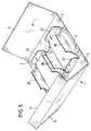
- FIG. 5 Container shape, which is illustrated in Fig. 3 by V + arrow, and runs as a glued essentially finished container, similar to the shape shown in Fig. 6, which is to illustrate the indication VI + arrow in Fig. 3, on the transport pad on the right in the drawing further through a turning station 41, in which the container 24 is turned by means of the turning device 42 into the position illustrated in FIG. 7, which is marked by the reference VII + arrow in FIG. 3, so that the individual compartments formed 25, which are now open at the top, in a directly connected expansion system 30a directly with the filling material 23 from a filling station n 43 can be filled.
- the container 24 with the filled compartments 25 can then be encased or encased in an outer packaging device 44, if desired in connection with a sealing device 45, with outer packaging material 46, for example a film pulled from a film roll 44a.
- outer packaging material 46 for example a film pulled from a film roll 44a.
- the container 48 for example foil-wrapped, can then be removed from the machine system 30 / 30a ready for dispatch, distribution and sale.
Landscapes
- Engineering & Computer Science (AREA)
- Mechanical Engineering (AREA)
- Cartons (AREA)
- Packages (AREA)
- Making Paper Articles (AREA)
Abstract
Description
Die Erfindung bezieht sich auf einen Zuschnitt zur Fertigung eines in zur Aufnahme von stückigem Füllgut geeignete Abteile abfallfrei aufgeteilten Behältnisses, der mindestens fünf durch parallele Längsfaltlinien verbundene rechteckige Plattenteile aufweist, die in dem fertigen Behältnis einen Boden, eine erste Seitenwand, eine gleichbreite zweite Seitenwand und einen zwischen den Seitenwänden gelegenen, eine Reihe von Abteil--Trennwänden ergebenden Plattenteil bilden, wobei diese Plattenteile eine Anzahl von quer verlaufenden Schnitten und eine Anzahl von zwischen seinen seitlichen Längsfaltlinien verlaufenden Querfaltlinien aufweist, und die Seitenplatten schräg vom Schnittpunkt einer Längsfaltlinie mit einer Querfaltlinie nach aussen bis zu weniger als der halben Breite der Seitenplattenteile verlaufende Faltlinien aufweisen.The invention relates to a blank for manufacturing a compartment suitable for holding bulk goods waste-free divided container that has at least five through parallel longitudinal folding lines connected rectangular plate parts has a bottom, a first in the finished container Sidewall, an equal width second sidewall and one between the side walls, a series of compartment partitions resultant plate part, these plate parts a number of transverse cuts and one Number of lines running between its lateral longitudinal fold lines Has transverse fold lines, and the side panels diagonally from the intersection of a longitudinal fold line with a transverse fold line outwards to less than half the width of the side panel parts have extending fold lines.
Zuschnitte dieser Art sind bekannt, beispielsweise aus den
US-Patentschriften 2 690 866 und 2 744 675 sowie aus der
EP-Publikation 0 729 893 A 2 der Anmelderin.
Zwar konnte mittels der aus EP 0 729 893 A 2 bekannten Ausführungsart
bereits in gewisser Weise die relative Instabilität
der aus Zuschnitten gemäss den US-Patentschriften
2 690 866 und 2 744 675 gefertigten Behältnissen verbessert
und der bei der Ausführungsart gemäss US-PS 2 744 675
störende Materialabfall trotzdem vermieden werden. Aber es
hat sich in der Praxis gezeigt, dass insbesondere dann, wenn
das Füllgut, für welches solche Behältnisse im speziellen
Einsatz bestimmt sind, relativ schwergewichtig ist und in
Formgestaltungen mit relativ grösseren Toleranzen vorliegt,
solche Behältnisse hinsichtlich ihrer Stabilitätseigenschaften
immer noch zu wünschen übrig lassen, insbesondere dann,
wenn sie aus vergleichsweise leichterem Material, wie beispielsweise
leichtem Karton oder leichter einseitiger Wellpappe,
beispielsweise Wellpappe-Material mit Flächengewichten
im Bereich von ca. 40 - 400 g/m2 bestehen sollen. Leichtgewichtiges
Material hat für diese Zwecke den extremen Vorteil,
dass es die Transport- und Entsorgungskosten der fertigen
Verpackungen so wenig wie möglich belastet; sein Einsatz ist
daher erwünscht.Blanks of this type are known, for example from US Pat. Nos. 2,690,866 and 2,744,675, and from the applicant's
Admittedly, by means of the embodiment known from
Die Aufgabe der Erfindung besteht darin, einen Zuschnitt zur Verfügung zu stellen, der die abfallfreie Fertigung von solchen Behältnissen mit stoss- und druckstabilen Seiten- und Abteile-Trennwänden aus jedem gewünschten, auch leichtgewichtigen Karton- und Pappe-, insbesondere Wellpappe-Bahnenmaterial in gewünschtenfalls kontinuierlicher Arbeitsweise und in einem System mit direktem Zugang zu einer Befüllungsanlage zum Einbringen des vorgesehenen Füllgutes und anschliessender verkaufsfertiger Umverpackung zu ermöglichen vermag.The object of the invention is a blank for To make available the waste-free manufacture of such Containers with shock and pressure stable side and Compartment partitions made of any desired, even lightweight Cardboard and cardboard, especially corrugated sheeting in continuous mode of operation if desired and in a system with direct access to a filling system for the introduction of the intended filling material and subsequent able to enable ready-for-sale packaging.
Diese Aufgabe wird erfindungsgemäss durch die im Kennzeichen
des Anspruchs 1 angegebenen Merkmale gelöst, wobei in den
Unteransprüchen 2 bis 5 noch zweckmässige und vorteilhafte
Ausgestaltungen des erfindungsgemässen Zuschnitts beansprucht
werden. According to the invention, this object is achieved by means of the
solved the features specified in
Die Ansprüche 6 und 7 kennzeichnen aus erfindungsgemässen
Zuschnitten herstellbare erfindungsgemässe Behältnisse und
die Ansprüche 8 bis 12 enthalten die Merkmale der erfindungsgemässen
Anlage zur kontinuierlichen Fertigung und gewünschtenfalls
Befüllung und Umverpackung der erfindungsgemässen Behältnisse.
Während die eingangs erläuterten bekannten Zuschnitte Behältnisse von relativ empfindlicher Stoss- und Druckanfälligkeit ergeben, gelingt es mittels erfindungsgemässe Zuschnitte, sowohl die Stabilität der Behälter-Längsseiten zu verbessern, weil in der Gebrauchsform erfindungsgemässer Behältnisse diese Seitenteile infolge der zusätzlichen innen gelegenen Klappenteile daran im wesentlichen doppel- bzw. dreilagig vorliegen; und es lässt sich auch die Stoss- und Druck-Belastbarkeit der Abteil-Trennwände erfindungsgemäss optimieren, weil diese in der Gebrauchsform des Behältnisses ebenfalls doppellagig und weiterhin bis zum Behälter-Innenboden reichend auffaltbar sind, so dass sie sich am Boden abzustützen vermögen. Darüber hinaus vermag die erfindungsgemässe Behältnis-Ausbildung mittels der eine abfedernde Wirkung ausübenden Klappenteile innen an den Abteil-Seitenetwa vorhandene Formatdiverganzen des stückigen Füllgutes in vergleichsweise grösseren Toleranzen auszugleichen, so dass feste Halterung von auch relativ verschieden geformtem stückigem Füllgut sicher garantiert ist.During the known blanks containers explained above of relatively sensitive to shock and pressure result, by means of cuts according to the invention, to improve the stability of the long sides of the container, because in the use form containers according to the invention these side panels due to the additional interior Flap parts thereon essentially two or three layers present; and it can also be the shock and pressure resistance optimize the compartment partitions according to the invention, because these are also in the use form of the container double-layered and continues to the bottom of the container are unfoldable so that they can support themselves on the ground. In addition, the container design according to the invention can by means of the damper parts exerting a cushioning effect Inside the compartment sides, there are some existing format divisions the lumpy product in comparatively larger Compensate tolerances, so that fixed mounting of too Relatively differently shaped lumpy filling is guaranteed is.
Als Material für erfindungsgemässe Zuschnitte sind beliebige bekannte Karton- und Pappematerialien, auch starkes Papier oder Vliesstoff-Material brauchbar, das aus wirtschaftlichen Gründen möglichst leichtgewichtig sein sollte. Das Flächengewicht des verwendeten Bahnenmaterials sollte zweckmässig im Bereich von 40 bis 400 g/m2 liegen. Any known cardboard and cardboard materials, including strong paper or nonwoven material, which should be as light as possible for economic reasons, can be used as the material for blanks according to the invention. The weight per unit area of the sheet material used should expediently be in the range from 40 to 400 g / m 2 .
Das Material kann gewünschtenfalls, je nach Einsatzzweck, mit fett- und/oder wasserabweisenden Beschichtungen versehen sein. Insbesondere dann werden fettdichte Papiersorten zweckmässig eingesetzt, wenn die erfindungsgemässen Zuschnitte für Behältnisse für Lebensmittel bestimmt sind.Depending on the application, the material can provided with grease and / or water repellent coatings be. Greaseproof paper types are particularly useful used when the blanks according to the invention for Containers are intended for food.
Es ist möglich, erfindungsgemässe Behältnisse aus entsprechendem
Bahnenmaterial direkt von der Rolle in einer speziellen erfindungsgemässen
Maschinenanlage zu fertigen, zu befüllen und
- überzogen mit Umverpackungsmaterial - versand- bzw. verkaufsfertig
zu gewinnen.
Eine solche Maschinenanlage kann beim Füllgut-Hersteller aufgestellt
werden, so dass sie kontinuierlich oder getaktet mit
der kontinuierlichen Produktion des Füllgutes zusammen zu
arbeiten vermag, was eine gute frische Qualität der verpackten
Ware garantiert und bei Verpackung von pharmazeutischen und
kosmetischen Füllgütern einwandfreie hygienische Bedingungen
sichert. Auf einer solchen Maschinenanlage können Behältnisse
in verschiedenen Dimensionen und/oder Unterteilungen sowie
mit und ohne Deckel gefertigt werden. Die Behältnisse können,
entsprechend der maximalen Breite der Wellpappenanlage, eine
maximale Länge von 2450 mm haben und mit mehreren, zum Beispiel
bis zu 8 Einzelabteilen gefertigt werden. Für die Praxis haben
sich erfindungsgemässe Behältnisse in Längen bis zu 800 mm mit
2 und 3 Einzelabteilen als besonders zweckmässig erwiesen.
Die Einzelabteile können - je nach Dicke der Füllgut-Stücke -
mit einem oder mehreren Füllgut-Stücken befüllt werden.It is possible to manufacture containers according to the invention from appropriate sheet material directly from the roll in a special machine system according to the invention, to fill them and to obtain them, ready for dispatch or sale, coated with outer packaging material.
Such a machine system can be set up at the product manufacturer so that it can work continuously or in cycles with the continuous production of the product, which guarantees good fresh quality of the packaged goods and ensures perfect hygienic conditions when packaging pharmaceutical and cosmetic products. Containers in various dimensions and / or subdivisions and with and without a lid can be produced on such a machine system. Depending on the maximum width of the corrugated cardboard system, the containers can have a maximum length of 2450 mm and can be manufactured with several, for example up to 8 individual compartments. In practice, containers according to the invention in lengths of up to 800 mm with 2 and 3 individual compartments have proven to be particularly useful. The individual compartments can - depending on the thickness of the filling pieces - be filled with one or more filling pieces.
Da das Bahnenmaterial erfindungsgemäss vollkommen abfallfrei verarbeitet wird, ist der Einsatz solcher erfindungsgemässer Maschinenanlagen auch im Lebensmittelbereich, zum Beispiel in Linie mit einer Backstrasse für Gebäckverpackung einsatzfähig. Es können auch kosmetische und pharmazeutische Produkte hygienisch einwandfrei so verpackt werden. According to the invention, the web material is completely waste-free is processed, the use of such according to the invention Machine systems also in the food sector, for example Can be used in line with a baking line for pastry packaging. It can also include cosmetic and pharmaceutical products be packed hygienically so.
Nachstehend wird die Erfindung anhand einiger in den Figuren dargestellten Ausführungsbeispiele näher beschrieben.
- Fig. 1
- zeigt einen erfindungsgemässen Zuschnitt in der Draufsicht;
- Fig. 2
- zeigt eine Maschinenanlage zum kontinuierlichen Herstellen der Zuschnitte sowie der Behältnisse daraus;
- Fig. 3
- zeigt perspektivisch eine ähnliche Anlage mit kontinuierlicher Zuführung von Füllgut, Befüllung und Umverpackung;
- Fig. 4
- zeigt einen Abschnitt einer in der Anlage gemäss Fig. 2 verwendeten Materialbahn;
- Fig. 5
- zeigt den Abschnitt der Fig. 4 in einer weiteren Arbeitsstufe, mit einzelnen bereits aufgerichteten Teilen und im beginnenden Faltvorgang;
- Fig. 6
- zeigt das in der Arbeitsstufe der Fig. 5 entstehende Behältnis kurz vor Ende des Faltvorgangs und vor dem Verkleben;
- Fig. 7
- zeigt das Behältnis der Fig. 6 nach Verkleben und nach einem Wendevorgang, in der Draufsicht: die durch Aufrichten entstandenen Einzel-Abteile in dem Behältnis liegen jetzt offen und können befüllt werden;
- Fig. 8
- zeigt einen Schnitt nach VIII-VIII in Fig. 7; und
- Fig. 9
- zeigt einen Schnitt nach IX-IX in Fig. 7.
- Fig. 1
- shows a blank according to the invention in plan view;
- Fig. 2
- shows a machine system for the continuous production of the blanks and the containers therefrom;
- Fig. 3
- shows in perspective a similar system with continuous supply of filling material, filling and outer packaging;
- Fig. 4
- shows a section of a material web used in the system according to FIG. 2;
- Fig. 5
- shows the section of Figure 4 in a further working stage, with individual parts already erected and in the beginning folding process;
- Fig. 6
- shows the container formed in the working stage of Figure 5 shortly before the end of the folding process and before gluing;
- Fig. 7
- 6 shows the container of FIG. 6 after gluing and after a turning process, in a top view: the individual compartments in the container which have been erected are now open and can be filled;
- Fig. 8
- shows a section along VIII-VIII in Fig. 7; and
- Fig. 9
- shows a section along IX-IX in Fig. 7.
Der in Fig. 1 dargestellte Zuschnitt umfasst sieben Plattenteile:
eine erste Bodenplatte 1 ist über eine Längsfaltlinie
6 mit einer ersten Seitenwandplatte 2 verbunden. Diese
steht über eine Längsfaltlinie 7 mit einer Zwischenplatte 3
und diese wiederum über eine Längsfaltlinie 8 mit einer zweiten
Seitenwandplatte 4 in Verbindung. Mit der Seitenwandplatte
4 ist über eine Längsfaltlinie 9 eine zweite Bodenplatte
5 verbunden, und an dieser hängt über eine Längsfaltlinie
12 ein zusätzliches Seitenwandteil 11, mit welchem über
eine weitere Längsfaltlinie 14 ein zusätzliches Deckelplattenteil
13 verbunden ist. The blank shown in Fig. 1 comprises seven plate parts:
a
Das Zwischenplattenteil 3 weist vier Querfaltlinien 10 auf,
von denen je eine an jeder der beiden Aussenlängskanten des
Zuschnitts gelegen ist. Diese beiden Aussenkanten-Querfaltlinien
10 können, wenn - nicht dargestellte - Einzelbehältnisse
hergestellt werden sollen, die befüllt ohne Umverpackung
gewünscht werden, in einer dem Fachmann zum Beispiel aus
EP 0 729 893 A 2 bekannten Weise über die Seitenwandplatten
2 und 4 und 11 sowie die Deckelplatte 13 und die Bodenplatten
1 und 5 verlängert sein, wobei dann - hier ebenfalls nicht
dargestellte - beidseitige Längsseite-Endteile mit entsprechenden
Schnitten und Falzungen im Verlauf jeder Längsfaltlinie
und mit entsprechend schräg verlaufenden Faltlinien dazwischen,
vorhanden sein können, die zur Bildung von Endwänden gestaltet
sind.The
Das Zwischenplattenteil 3 weist weiterhin drei quer verlaufende
Schnitte 18 und je drei parallel zu den Faltlinien 7 bzw. 8
in einem gewissen Abstand von diesen längsverlaufende Zusatzschnitte
17 auf, die in der Mitte von den Schnitten 18 geschnitten
werden. An den Zusatzschnitten 17 setzen an deren beiderseitigen
Endpunkten schräg zu den Längsfaltlinien 7 bzw. 8 verlaufende
zweite Zusatzschnitte 19 an, die ihre Fortsetzung
finden in quer verlaufenden dritten Zusatzschnitten 15, die
vom Schnittpunkt der Schnitte 19 mit den Längsfaltlinien 7
bzw. 8 bis je zu einem Endpunkt 15a in den Seitenteilen 2
bzw. 4 verlaufen. Zwischen den je einer Schnittfolge
15/19/17/19/15 zugehörigen beiden Endpunkten 15a ist je eine
zusätzliche Längsfaltlinie 20 vorhanden, und diese ist mit den
an den Endpunkten 15a ansetzenden je schräg zu den Querfaltlinien
10 verlaufenden Faltlinien 16 verbunden. Es sind dadurch
begrenzte Felder 21 vorhanden, die - wie insbesondere anschaulich
auch in Fig. 4 zu sehen - sechseckig geformt sind. Die
Felder 21 bilden beim Aufrichten und Auffalten des Zuschnitts
zu einem Behältnis 24 - dieser Vorgang ist schrittweise in
den Figuren 4, 5, 6 und 7 an einem Zuschnitt aus sechs Plattenteilen
1, 2, 3, 4, 5 und 11 (ohne Deckelteil) mit den fünf
Längsfaltlinien 6, 7, 8, 9 und 12 veranschaulicht - federnde
Seitenklappenteile 21a, während zwischen den Querfaltlinien 10
und den quer verlaufenden Schnitten 18 gelegene Rechteckteile
26 mit teilweise ausgeschnittenen Seitenrändern beim Aufrichten
die Trennwände 22 der einzelnen Abteile 25 im fertigen Behältnis
24 bilden. Die mittlere Querfaltlinie 10 ist bei dem
Zuschnitt der Fig. 4 als ein paralleles Paar von Querfaltlinien
vorhanden, und dementsprechend hat die mittlere Trennwand 22
in dem aus diesem Zuschnitt aufgerichteten Behältnis 24 eine
stegförmige Ausbildung, wie gut aus den Figuren 7 und 8 zu
ersehen ist.The
Beim Faltvorgang um die Längsfaltlinien 6, 7, 8, 9 und 12
wird das Bodenplattenteil 1 um 90° gebogen, so dass nun das
Bodenplattenteil 1 über die aufgerichteten Rechteckteile 26,
die die Trennstege 22 bilden, zu liegen kommt, während an die
Seitenplattenteile 2 und 4 als Verstärkung die gleichzeitig
um die Faltlinie 20 um 180° nach innen gebogenen Klappenteile
21a und die seitlich nach innen um die Faltlinien 16 umgefalzten
dreieckigen Randteile zu liegen kommen. Umd weiterhin wird
das Bodenplattenteil 5 um 90° so um die Längsfaltlinie 9 umgeknickt,
dass es das Bodenplattenteil 1 bedeckt und so den
Boden das Behältnisses 24 doppelt, während das zusätzliche
Seitenwand-Plattenteil 11, nachdem es mindestens teilweise
auf seiner nahe der Längsfaltlinie 12 gelegenen Innenfläche
mit Klebemittel beaufschlagt worden ist, in der aus Fig. 6 ersichtlichen
Form um 90° in der Längsfaltlinie 12 geknickt und
mit der Seitenwand 2, diese von aussen doppelnd, verklebt wird. When folding around the
Nach dem Wenden des danach fertigen Behältnisses 24 hat dieses
die aus Fig. 7 in der Draufsicht gezeigte Form und ist parat
zum Befülltwerden mit dem Füllgut, wie dies durch den Pfeil in
Fig. 7 und die oberhalb des Behältnisses dargestellten Füllgut-Körper
23 veranschaulicht ist.After turning the
In Fig. 8 erkennt man, dass in gefülltem Zustand des Behältnisses
24 das Füllgut 23 fest gehalten ist, einmal durch die
die Trennwände bildenden Rechteckteile 26, die auf dem Innenboden
1 abstützen und so sehr stabil sind und eine gewisse
seitliche Druckwirkung auf das Füllgut haben (Fig. 8), und
zum anderen durch die federnden Seitenklappenteile 21a an den
Seitenwandteilen 2 und 4 (Fig. 9).In Fig. 8 you can see that in the filled state of the
In an sich bekannter Weise kann das mit dem Füllgut befüllte Behältnis mit einer Umverpackung umhüllt werden, beispielsweise mit einer an sich bekannten Folienverpackung, die in dem Fachmann bekannter Weise bedruckt, durchsichtig oder undurchsichtig, versiegelt oder sosntwie verschlossen sein kann.In a manner known per se, that which is filled with the filling material Be wrapped with an outer packaging, for example with a known foil packaging, which in the Printed, transparent or opaque in a manner known to a person skilled in the art, sealed or otherwise sealed.
In den Figuren 2 und 3 ist eine Maschinenanlage 30/30a zur
Verwendung für ein kontinuierlich arbeitendes System zum
Herstellen erfindungsgmässer Zuschnitte und daraus gefertigter
erfindungsgemässer Behältnisse und zum Befüllen dieser Behältnisse
unmittelbar an dem Fabrikationsort für das Füllgut
beispielsweise veranschaulicht.A
Von einer Vorratsrolle 31 des Bahnenmaterials für die Zuschnitte,
beispielsweise einer einseitigen Wellpappe mit
einem Flächengewicht von 100 g/m2, wird mittels nicht gezeigter
Zugmittel die Materialbahn 29 über eine Umlenkrolle
32 auf eine Führungsunterlagebahn 33 gebracht und darauf
einer Stanz- und Rillstation 34 zugeführt, in welcher die
erfindungsgemässen Zuschnitte mittels Stanz- und Rillvorrichtungen
35 aus dem Bahnenmaterial gefertigt werden.
Es entstehen dort die in Fig. 4 veranschaulichten Zuschnitte,
was durch IV + Pfeil in Fig. 3 illustriert ist. Der Zuschnitt
läuft in Bahnlaufrichtung nach rechts in den Figuren 2 und 3
weiter in eine Aufrichtvorrichtung 36/37 und dann weiter in
die nachgeschaltete Klebstoffauftrags- und Faltstation 38 mit
Faltvorrichtung 39 und Klebstoffauftragsvorrichtung 40. Darin
nimmt der Zuschnitt die in Fig. 5 veranschaulichte beinahe
fertige Behältnisform an, was in Fig. 3 durch V + Pfeil illustriert
ist, und läuft als verklebtes im wesentlichen fertiges
Behältnis, ähnlich der in Fig. 6 gezeigten Form, was die Angabe
VI + Pfeil in Fig. 3 veranschaulichen soll, auf der Transportunterlage
nach rechts in der Zeichnung weiter durch eine
Wendestation 41, in der das Behältnis 24 mittels der Wendevorrichtung
42 in die in Fig. 7 veranschaulichte Lage gewendet
wird, was durch den Hinweis VII + Pfeil in Fig. 3 markiert ist,
so dass die einzelnen gebildeten Abteile 25, die nun nach oben
offen liegen, in einer unmittelbar nachgeschalteten Erweiterungsanlage
30a direkt mit dem Füllgut 23 aus einer Füllstation
43 befüllt werden können. Anschliessend kann in einer Umverpackungsvorrichtung
44, gewünschtenfalls in Verbindung mit einer
Siegelvorrichtung 45, das Behältnis 24 mit den befüllten
Abteilen 25 mit Umverpackungsmaterial 46, zum Beispiel einer
von einer Folienrolle 44a abgezogenen Folie, umhüllt bzw. ummantelt
werden. Sodann kann das mit Füllgut befüllte, zum Beispiel
folienumverpackte Behältnis 48 versand-, vertriebs- und
verkaufsfertig der Maschinenanlage 30/30a entnommen werden.From a
Wenn bruchempfindliches Füllgut, zum Beispiel aus einer Backstrasse
47 direkt in die Füllstation 43 ankommendes leichtes
Gebäck, in die Behältnisse 24 eingefüllt werden muss, kann
dies in der Füllstation auch von hand durch (nicht veranschaulichte)
Hilfspersonen sorgfältig erfolgen, ohne dass der kontinuierliche
Arbeitsgang unterbrochen werden muss. If break-sensitive contents, for example from a
- 11
- BodenplattenteilBase plate part
- 22nd
- SeitenwandplattenteilSidewall plate part
- 33rd
- ZwischenwandplattenteilPartition panel part
- 44th
- SeitenwandplattenteilSidewall plate part
- 55
- BodenplattenteilBase plate part
- 66
- Längsfaltlinie (zwischen 1 + 2)Longitudinal folding line (between 1 + 2)
- 77
- Längsfaltlinie (zwischen 2 + 3)Longitudinal folding line (between 2 + 3)
- 88th
- Längsfaltlinie (zwischen 3 + 4)Longitudinal folding line (between 3 + 4)
- 99
- Längsfaltlinie (zwischen 4 + 5)Longitudinal folding line (between 4 + 5)
- 1010th
- Querfaltlinien in 3Cross fold lines in 3
- 1111
- zusätzliches Seitenwand-Plattenteiladditional side wall plate part
- 1212th
- Längsfaltlinie (zwischen 5 + 11)Longitudinal folding line (between 5 + 11)
- 1313
- zusätzliches Deckel-Plattenteiladditional cover plate part
- 1414
- Längsfaltlinie (zwischen 11 + 13)Longitudinal folding line (between 11 + 13)
- 1515
- querverlaufende dritte Zusatzschnitte in 2transverse third Additional cuts in 2
- 15a15a
- Endpunkte von 15Endpoints of 15
- 1616
- schräg verlaufende Faltlinien in 2 bzw. 4sloping Fold lines in 2 and 4 respectively
- 1717th
- längsverlaufende Zusatzschnitte in 3longitudinal end Additional cuts in 3
- 1818th
- querverlaufende Schnitte in 3transverse Cuts in 3
- 1919th
- schräg verlaufende zweite Zusatzschnitte in 3sloping second Additional cuts in 3
- 2020th
- Zusatz-LängsfaltlinienAdditional longitudinal folding lines
- 2121
- sechseck-förmige Felderhexagonal fields
- 2222
- TrennwändePartitions
- 2323
- FüllgutProduct
- 2424th
- Behältniscontainer
- 2525th
- Einzel-AbteileIndividual compartments
- 2626
- Rechteck-Teile Rectangle parts
- 2929
- MaterialbahnMaterial web
- 3030th
- MaschinenanlageMachine system
- 30a30a
- Erweiterungsanlage zu 30Extension system to 30
- 3131
- VorratsrolleSupply roll
- 3232
- UmlenkrollePulley
- 3333
- FührungsunterlagebahnGuide subway
- 3434
- Stanz- und RillstationPunching and creasing station
- 3535
- Stanz- und RillvorrichtungPunching and creasing device
- 36/3736/37
- AufrichtvorrichtungRaising device
- 3838
- Klebeauftrags- und FaltstationGlue application and folding station
- 3939
- FaltvorrichtungFolding device
- 4040
- KlebeauftragsvorrichtungAdhesive application device
- 4141
- WendestationTurning station
- 4242
- WendevorrichtungTurning device
- 4343
- FüllstationFilling station
- 4444
- UmverpackungsvorrichtungRepackaging device
- 44a44a
- FolienrolleFoil roll
- 4545
- SiegelvorrichtungSealing device
- 4646
- UmverpackungsmaterialOuter packaging material
- 4747
- BackstrasseBackstrasse
- 4848
- gefülltes, folienumverpacktes verkaufsfertiges Behältnisfilled, foil wrapped ready-to-sell container
Claims (12)
Priority Applications (5)
| Application Number | Priority Date | Filing Date | Title |
|---|---|---|---|
| DK97250261T DK0905032T3 (en) | 1997-09-09 | 1997-09-09 | Subject matter for the manufacture of a container and a container made therefrom and a manufacturing plant therefor |
| EP97250261A EP0905032B1 (en) | 1997-09-09 | 1997-09-09 | Blank and container therefrom as well as manufacturing apparatus therefor |
| DE59709279T DE59709279D1 (en) | 1997-09-09 | 1997-09-09 | Cutting for the manufacture of a container and container made therefrom and a production plant therefor |
| US08/978,417 US6006983A (en) | 1997-09-09 | 1997-11-25 | Blank for producing a container and a container produced therefrom |
| CA002224509A CA2224509A1 (en) | 1997-09-09 | 1997-12-11 | Blank for producing a container and a container produced therefrom |
Applications Claiming Priority (3)
| Application Number | Priority Date | Filing Date | Title |
|---|---|---|---|
| EP97250261A EP0905032B1 (en) | 1997-09-09 | 1997-09-09 | Blank and container therefrom as well as manufacturing apparatus therefor |
| US08/978,417 US6006983A (en) | 1997-09-09 | 1997-11-25 | Blank for producing a container and a container produced therefrom |
| CA002224509A CA2224509A1 (en) | 1997-09-09 | 1997-12-11 | Blank for producing a container and a container produced therefrom |
Publications (2)
| Publication Number | Publication Date |
|---|---|
| EP0905032A1 true EP0905032A1 (en) | 1999-03-31 |
| EP0905032B1 EP0905032B1 (en) | 2003-02-05 |
Family
ID=31720850
Family Applications (1)
| Application Number | Title | Priority Date | Filing Date |
|---|---|---|---|
| EP97250261A Expired - Lifetime EP0905032B1 (en) | 1997-09-09 | 1997-09-09 | Blank and container therefrom as well as manufacturing apparatus therefor |
Country Status (5)
| Country | Link |
|---|---|
| US (1) | US6006983A (en) |
| EP (1) | EP0905032B1 (en) |
| CA (1) | CA2224509A1 (en) |
| DE (1) | DE59709279D1 (en) |
| DK (1) | DK0905032T3 (en) |
Cited By (1)
| Publication number | Priority date | Publication date | Assignee | Title |
|---|---|---|---|---|
| WO2016027141A1 (en) * | 2014-08-19 | 2016-02-25 | Kraft Foods R & D, Inc. | Packaging and a method of manufacture thereof |
Families Citing this family (7)
| Publication number | Priority date | Publication date | Assignee | Title |
|---|---|---|---|---|
| US6266919B1 (en) * | 1999-01-20 | 2001-07-31 | J. R. Johnson Supply, Inc. | Method and apparatus for containing plants |
| CL2004001164A1 (en) * | 2003-05-23 | 2005-05-20 | Colgate Palmolive Co | METHOD FOR WRAPPING PRODUCTS THAT HAVE A LARGER DIMENSION AND A LOWER DIMENSION, THAT INCLUDES PROVIDING A ROLL OF SHEETED MATERIAL; CUT LOTS OF EDGE OF SUCH ROLL; ENTER THE MODIFIED SHEET MATERIAL AND SEAL THE FINS |
| AU2009355809B2 (en) * | 2009-11-25 | 2013-05-09 | Pringles S.A.R.L. | Packaged food product |
| DE102010037947A1 (en) | 2010-10-04 | 2012-04-05 | Pillopak B.V. | Cut, particularly corrugated cardboard cut, for manufacturing compartment fitted in separated container for admission of fragmented filling material, has five rectangular plate sections connected by folding lines |
| EP2487115B1 (en) | 2011-02-11 | 2016-02-03 | PilloPak b.v. | Blank, container and method |
| DE102011109431A1 (en) * | 2011-08-04 | 2013-02-07 | Bsn Medical Gmbh | Temporary rail |
| DE102015216600B4 (en) | 2015-08-31 | 2017-05-04 | Karl Knauer Kg | Folding box for receiving rounded objects, folding carton blank for a folding box and method for forming the folding box |
Citations (4)
| Publication number | Priority date | Publication date | Assignee | Title |
|---|---|---|---|---|
| US2635512A (en) * | 1951-01-31 | 1953-04-21 | Clybourn Machine Corp | Machine for making fibrous boxes |
| US4347969A (en) * | 1981-05-08 | 1982-09-07 | Weyerhaeuser Company | Tray |
| US4489879A (en) * | 1983-05-25 | 1984-12-25 | Champion International Corporation | Multi-compartmented food serving tray and blank therefor |
| EP0729893A2 (en) * | 1995-03-01 | 1996-09-04 | Nederlandse Pillo-Pak Maatschappij B.V. | Blank for a tray having partitions |
Family Cites Families (5)
| Publication number | Priority date | Publication date | Assignee | Title |
|---|---|---|---|---|
| US1922571A (en) * | 1931-02-05 | 1933-08-15 | Irving A Deline | Box construction |
| US2690866A (en) * | 1947-08-25 | 1954-10-05 | R H Filmer Ltd | Box |
| US2605035A (en) * | 1950-08-03 | 1952-07-29 | Nat Folding Box Company Inc | Carrier for bottles and cans |
| US2717116A (en) * | 1952-04-11 | 1955-09-06 | Alford Cartons | Carton |
| US2744675A (en) * | 1952-04-23 | 1956-05-08 | Allied Plastics Co | Shipping container |
-
1997
- 1997-09-09 DE DE59709279T patent/DE59709279D1/en not_active Expired - Fee Related
- 1997-09-09 EP EP97250261A patent/EP0905032B1/en not_active Expired - Lifetime
- 1997-09-09 DK DK97250261T patent/DK0905032T3/en active
- 1997-11-25 US US08/978,417 patent/US6006983A/en not_active Expired - Fee Related
- 1997-12-11 CA CA002224509A patent/CA2224509A1/en not_active Abandoned
Patent Citations (4)
| Publication number | Priority date | Publication date | Assignee | Title |
|---|---|---|---|---|
| US2635512A (en) * | 1951-01-31 | 1953-04-21 | Clybourn Machine Corp | Machine for making fibrous boxes |
| US4347969A (en) * | 1981-05-08 | 1982-09-07 | Weyerhaeuser Company | Tray |
| US4489879A (en) * | 1983-05-25 | 1984-12-25 | Champion International Corporation | Multi-compartmented food serving tray and blank therefor |
| EP0729893A2 (en) * | 1995-03-01 | 1996-09-04 | Nederlandse Pillo-Pak Maatschappij B.V. | Blank for a tray having partitions |
Cited By (3)
| Publication number | Priority date | Publication date | Assignee | Title |
|---|---|---|---|---|
| WO2016027141A1 (en) * | 2014-08-19 | 2016-02-25 | Kraft Foods R & D, Inc. | Packaging and a method of manufacture thereof |
| CN106573691A (en) * | 2014-08-19 | 2017-04-19 | 卡夫食品研究和开发股份有限公司 | Packaging and a method of manufacture thereof |
| US11945621B2 (en) | 2014-08-19 | 2024-04-02 | Kraft Foods Schweiz Holding Gmbh | Packaging and a method of manufacture thereof |
Also Published As
| Publication number | Publication date |
|---|---|
| DK0905032T3 (en) | 2003-05-26 |
| DE59709279D1 (en) | 2003-03-13 |
| CA2224509A1 (en) | 1999-06-11 |
| US6006983A (en) | 1999-12-28 |
| EP0905032B1 (en) | 2003-02-05 |
Similar Documents
| Publication | Publication Date | Title |
|---|---|---|
| EP0726205B1 (en) | Blanks for a transport and display container | |
| DE60010717T2 (en) | EASY TO OPEN LIFTING TANK | |
| DE2136843A1 (en) | Packing bag | |
| CH643507A5 (en) | PACKAGE WITH A GROUP OF ITEMS, METHOD AND CUT FOR PRODUCTION THEREOF. | |
| CH629437A5 (en) | Carton, method for its manufacture, and blank for carrying out the method | |
| CH422501A (en) | Process for the production of sacks, bags, boxes or similar containers with a square bottom | |
| DE2305538A1 (en) | PACKAGING CONTAINER | |
| EP0905032B1 (en) | Blank and container therefrom as well as manufacturing apparatus therefor | |
| CH448872A (en) | Corrugated cardboard containers | |
| EP0609784B1 (en) | Foldable packaging container and blank therefor | |
| CH651260A5 (en) | PACKING DEVICE FOR INSERTING IN A TUBE-SHAPED OUTER BOX. | |
| WO1991018807A1 (en) | Packaging-material body | |
| CH398444A (en) | Foldable and erectable folding box | |
| DE60004774T2 (en) | Box with two staggered dispensing openings | |
| CH539548A (en) | Folded container with bottom and side parts made from at least one blank of foldable rigid material | |
| DE2128214A1 (en) | Folding box | |
| DE4311643C2 (en) | Process for the production of filling material from molded parts | |
| DE3730768A1 (en) | Packaging container, in particular for receiving bars of chocolate | |
| DE1586438A1 (en) | Packaging box with a depressed lid field | |
| DE3203034A1 (en) | Corrugated cardboard blank for sales stands | |
| DE2353218C3 (en) | Method for folding a blank for packaging with a web insert | |
| DE2013269A1 (en) | Cardboard box with folding lid | |
| DE1942910C (en) | Packaging for berries or the like | |
| CH351895A (en) | Folding box | |
| DE69904556T2 (en) | Cartonboards divisible into two parts |
Legal Events
| Date | Code | Title | Description |
|---|---|---|---|
| PUAI | Public reference made under article 153(3) epc to a published international application that has entered the european phase |
Free format text: ORIGINAL CODE: 0009012 |
|
| AK | Designated contracting states |
Kind code of ref document: A1 Designated state(s): BE CH DE DK FR GB LI NL |
|
| 17P | Request for examination filed |
Effective date: 19990924 |
|
| AKX | Designation fees paid |
Free format text: BE CH DE DK FR GB LI NL |
|
| 17Q | First examination report despatched |
Effective date: 20020502 |
|
| RAP1 | Party data changed (applicant data changed or rights of an application transferred) |
Owner name: PILLOPAK B.V |
|
| GRAH | Despatch of communication of intention to grant a patent |
Free format text: ORIGINAL CODE: EPIDOS IGRA |
|
| GRAH | Despatch of communication of intention to grant a patent |
Free format text: ORIGINAL CODE: EPIDOS IGRA |
|
| GRAA | (expected) grant |
Free format text: ORIGINAL CODE: 0009210 |
|
| AK | Designated contracting states |
Designated state(s): BE CH DE DK FR GB LI NL |
|
| REG | Reference to a national code |
Ref country code: GB Ref legal event code: FG4D Free format text: NOT ENGLISH |
|
| REG | Reference to a national code |
Ref country code: CH Ref legal event code: EP |
|
| REF | Corresponds to: |
Ref document number: 59709279 Country of ref document: DE Date of ref document: 20030313 Kind code of ref document: P |
|
| GBT | Gb: translation of ep patent filed (gb section 77(6)(a)/1977) |
Effective date: 20030327 |
|
| REG | Reference to a national code |
Ref country code: CH Ref legal event code: NV Representative=s name: LUCHS & PARTNER PATENTANWAELTE |
|
| REG | Reference to a national code |
Ref country code: DK Ref legal event code: T3 |
|
| ET | Fr: translation filed | ||
| PGFP | Annual fee paid to national office [announced via postgrant information from national office to epo] |
Ref country code: CH Payment date: 20030901 Year of fee payment: 7 |
|
| PGFP | Annual fee paid to national office [announced via postgrant information from national office to epo] |
Ref country code: DK Payment date: 20030903 Year of fee payment: 7 |
|
| PGFP | Annual fee paid to national office [announced via postgrant information from national office to epo] |
Ref country code: BE Payment date: 20031001 Year of fee payment: 7 |
|
| PLBE | No opposition filed within time limit |
Free format text: ORIGINAL CODE: 0009261 |
|
| STAA | Information on the status of an ep patent application or granted ep patent |
Free format text: STATUS: NO OPPOSITION FILED WITHIN TIME LIMIT |
|
| 26N | No opposition filed |
Effective date: 20031106 |
|
| PGFP | Annual fee paid to national office [announced via postgrant information from national office to epo] |
Ref country code: DE Payment date: 20040823 Year of fee payment: 8 |
|
| PGFP | Annual fee paid to national office [announced via postgrant information from national office to epo] |
Ref country code: GB Payment date: 20040830 Year of fee payment: 8 |
|
| PGFP | Annual fee paid to national office [announced via postgrant information from national office to epo] |
Ref country code: NL Payment date: 20040909 Year of fee payment: 8 |
|
| PGFP | Annual fee paid to national office [announced via postgrant information from national office to epo] |
Ref country code: FR Payment date: 20040910 Year of fee payment: 8 |
|
| PG25 | Lapsed in a contracting state [announced via postgrant information from national office to epo] |
Ref country code: LI Free format text: LAPSE BECAUSE OF NON-PAYMENT OF DUE FEES Effective date: 20040930 Ref country code: DK Free format text: LAPSE BECAUSE OF NON-PAYMENT OF DUE FEES Effective date: 20040930 Ref country code: CH Free format text: LAPSE BECAUSE OF NON-PAYMENT OF DUE FEES Effective date: 20040930 Ref country code: BE Free format text: LAPSE BECAUSE OF NON-PAYMENT OF DUE FEES Effective date: 20040930 |
|
| BERE | Be: lapsed |
Owner name: *PILLOPAK B.V. Effective date: 20040930 |
|
| REG | Reference to a national code |
Ref country code: CH Ref legal event code: PL |
|
| REG | Reference to a national code |
Ref country code: DK Ref legal event code: EBP |
|
| PG25 | Lapsed in a contracting state [announced via postgrant information from national office to epo] |
Ref country code: GB Free format text: LAPSE BECAUSE OF NON-PAYMENT OF DUE FEES Effective date: 20050909 |
|
| PG25 | Lapsed in a contracting state [announced via postgrant information from national office to epo] |
Ref country code: NL Free format text: LAPSE BECAUSE OF NON-PAYMENT OF DUE FEES Effective date: 20060401 Ref country code: DE Free format text: LAPSE BECAUSE OF NON-PAYMENT OF DUE FEES Effective date: 20060401 |
|
| GBPC | Gb: european patent ceased through non-payment of renewal fee |
Effective date: 20050909 |
|
| PG25 | Lapsed in a contracting state [announced via postgrant information from national office to epo] |
Ref country code: FR Free format text: LAPSE BECAUSE OF NON-PAYMENT OF DUE FEES Effective date: 20060531 |
|
| NLV4 | Nl: lapsed or anulled due to non-payment of the annual fee |
Effective date: 20060401 |
|
| REG | Reference to a national code |
Ref country code: FR Ref legal event code: ST Effective date: 20060531 |
|
| BERE | Be: lapsed |
Owner name: *PILLOPAK B.V. Effective date: 20040930 |