EP0904722A2 - Dispenser for antimicrobial liquids - Google Patents
Dispenser for antimicrobial liquids Download PDFInfo
- Publication number
- EP0904722A2 EP0904722A2 EP98124233A EP98124233A EP0904722A2 EP 0904722 A2 EP0904722 A2 EP 0904722A2 EP 98124233 A EP98124233 A EP 98124233A EP 98124233 A EP98124233 A EP 98124233A EP 0904722 A2 EP0904722 A2 EP 0904722A2
- Authority
- EP
- European Patent Office
- Prior art keywords
- actuator
- reservoir
- assembly
- piston
- container assembly
- Prior art date
- Legal status (The legal status is an assumption and is not a legal conclusion. Google has not performed a legal analysis and makes no representation as to the accuracy of the status listed.)
- Granted
Links
- 0 *C(CCC1)N*1C=* Chemical compound *C(CCC1)N*1C=* 0.000 description 1
Images


Classifications
-
- A—HUMAN NECESSITIES
- A47—FURNITURE; DOMESTIC ARTICLES OR APPLIANCES; COFFEE MILLS; SPICE MILLS; SUCTION CLEANERS IN GENERAL
- A47K—SANITARY EQUIPMENT NOT OTHERWISE PROVIDED FOR; TOILET ACCESSORIES
- A47K5/00—Holders or dispensers for soap, toothpaste, or the like
- A47K5/06—Dispensers for soap
- A47K5/12—Dispensers for soap for liquid or pasty soap
- A47K5/1202—Dispensers for soap for liquid or pasty soap dispensing dosed volume
- A47K5/1204—Dispensers for soap for liquid or pasty soap dispensing dosed volume by means of a rigid dispensing chamber and pistons
- A47K5/1207—Dispensing from the bottom of the dispenser with a vertical piston
-
- A—HUMAN NECESSITIES
- A47—FURNITURE; DOMESTIC ARTICLES OR APPLIANCES; COFFEE MILLS; SPICE MILLS; SUCTION CLEANERS IN GENERAL
- A47K—SANITARY EQUIPMENT NOT OTHERWISE PROVIDED FOR; TOILET ACCESSORIES
- A47K5/00—Holders or dispensers for soap, toothpaste, or the like
- A47K5/06—Dispensers for soap
- A47K5/12—Dispensers for soap for liquid or pasty soap
- A47K5/1202—Dispensers for soap for liquid or pasty soap dispensing dosed volume
- A47K5/1204—Dispensers for soap for liquid or pasty soap dispensing dosed volume by means of a rigid dispensing chamber and pistons
-
- B—PERFORMING OPERATIONS; TRANSPORTING
- B05—SPRAYING OR ATOMISING IN GENERAL; APPLYING FLUENT MATERIALS TO SURFACES, IN GENERAL
- B05B—SPRAYING APPARATUS; ATOMISING APPARATUS; NOZZLES
- B05B11/00—Single-unit hand-held apparatus in which flow of contents is produced by the muscular force of the operator at the moment of use
- B05B11/01—Single-unit hand-held apparatus in which flow of contents is produced by the muscular force of the operator at the moment of use characterised by the means producing the flow
- B05B11/10—Pump arrangements for transferring the contents from the container to a pump chamber by a sucking effect and forcing the contents out through the dispensing nozzle
- B05B11/1097—Pump arrangements for transferring the contents from the container to a pump chamber by a sucking effect and forcing the contents out through the dispensing nozzle with means for sucking back the liquid or other fluent material in the nozzle after a dispensing stroke
Definitions
- the present invention relates generally to product dispensers, and more particularly to liquid or fluid dispensers specially adapted to dispense cleansing, disinfecting or sterilizing products such as antiseptic soaps, hydroalcoholic solutions, disinfecting lotions, cleaning solutions and other antimicrobial liquids.
- antiseptic preparation of a surgeon's hands conventionally includes a prolonged hand and lower arm scrubbing with an antimicrobial soap.
- the antimicrobial soap is typically dispensed from a liquid soap dispenser mounted near a scrub sink.
- antimicrobial soap dispensers are designed to be operated without hand contact by mechanical, pneumatic or electromechanical means.
- U.S. Patent No. 3,203,597 discloses a surgical soap dispenser which includes a complex bracket/actuator assembly and a bottle/pump assembly.
- the entire fluid (soap) path is provided in the bottle/pump assembly.
- the bottle/pump assembly is disposable in order to resist contamination build up in the fluid path.
- the bracket/actuator assembly is intended to be reusable and must itself be cleaned and disinfected.
- the bracket/actuator assembly comprises a complex structure including keyways and cam surfaces. This complex structure may tend to collect debris and make it very difficult to clean.
- a container assembly for a product dispenser which (1) affords quick, convenient set up, refill and maintenance without requiring excessive user handling, (2) is easily cleaned, (3) reduces opportunities for contamination build up in its product path, (4) may optionally provide precise, repeatable metered amounts of product, regardless of the volume of product in a reservoir, (5) has a low profile, (6) optionally includes a novel nozzle for reducing dripping, waste, drying and clogging, (7) may be actuated without hand contact to avoid contamination due to actuation, and (8) includes container and bracket/actuator assemblies and an attachment mechanism which automatically aligns elements of the container and bracket/actuator assemblies without the need for excessive handling.
- a container assembly that is attachable to a bracket/actuator assembly.
- the bracket/actuator assembly has a movable actuator and a pair of mounting flanges.
- the actuator is movable between a retracted position which affords attachment of the container assembly to the bracket/actuator assembly and an extended position that is spaced from the retracted position.
- the container assembly comprises a reservoir for holding product to be dispensed, an outlet sized and shaped to afford passage of product to be dispensed, and a pump that is operatively associated with the actuator.
- the pump includes a driven surface for receiving the actuator. The driven surface is adapted to be driven by the actuator when the actuator moves from the retracted to the extended position.
- the container assembly also includes a pair of channels which are sized and shaped to cooperatively receive the mounting flanges of the bracket/actuator assembly to attach the container assembly to the bracket/actuator assembly and to align the driven surface of the pump with the actuator when the container assembly is attached to the bracket/actuator assembly.
- the container assembly is attachable to the bracket/actuator assembly in a vertically downward direction.
- the channels of the bracket/actuator assembly are elongate and situated so that they taper toward each other in the direction of attachment so that the driven surface of the pump is guided into a predetermined orientation relative to the actuator upon attachment of the container assembly to the bracket/actuator assembly.
- the container assembly includes a valve assembly having inner surfaces.
- the inner surfaces receive the pump and define a pump chamber.
- the valve assembly also has outer surfaces including sealing surfaces for sealing the reservoir, and grasping surfaces that are sized and shaped to be manually grasped.
- the valve assembly also includes the outlet. Surfaces extend between the inner and outer surfaces to define a fill hole for the pump chamber.
- the valve assembly is adapted to move between a sealed position with the sealing surfaces sealing the pump chamber from the reservoir, and a dispense position with the fill hole affording passage of the product from the reservoir to the pump chamber.
- the present invention may be viewed as a unique method of dispensing product.
- the present invention is directed to a dispenser 30 (or components thereof) for dispensing product.
- the dispenser 30 comprises a container assembly 32 ( Figure 3) which is removably attachable to a bracket/actuator assembly 34.
- the bracket/actuator assembly 34 includes an actuator 196 that is movable between a retracted position (see Figure 3, Figure 25, solid lines) which affords attachment of the container assembly 32 to the bracket/actuator assembly 34 and an extended position ( Figure 25, dashed lines).
- the bracket/actuator assembly 34 also includes a pair of inwardly directed mounting flanges 200 and 202 which will be described in greater detail below.
- the container assembly 32 includes a reservoir for holding product to be dispensed.
- the dispenser 30 is particularly suitable for dispensing cleansing, disinfecting or sterilizing liquids, fluids, compositions or solutions, such as antiseptic soaps, hydroalcoholic solutions, disinfecting lotions, cleaning solutions and other antimicrobial liquids.
- the product may comprise the compositions described in PCT Publication No. WO/97/00667 and PCT Publication No. WO/97/00668.
- the dispenser 30 is particularly suitable for dispensing antimicrobial liquids that include volatile active ingredients, may other compositions may be dispensed from the dispenser 30.
- the reservoir is provided by bottle 36 which is shown in Figures 10 and 11.
- the actuator 196 of the bracket/actuator assembly 34 is preferably controlled without hand or arm contact with the dispenser 30 to reduce the risk of contamination due to actuation of the dispenser 30.
- Figure 1 illustrates a foot actuated pneumatic bladder pump 220 with an air hose 221 adapted to be connected to port 214.
- the bladder pump 220 may optionally be used to move the actuator 196 from the retracted position to the extended position by delivering pneumatic pressure to the bracket/actuator assembly 34 when depressed by the operator.
- a wide variety of structures may be used to operate the bracket/actuator assembly 34 without hand contact.
- a wide variety of devices may be used which are designed to engage a user's foot, knee, elbow or even the user's hand.
- an electronic eye may be used to activate the dispenser 30.
- a wide variety of devices may be used to propel the actuator 196 between the retracted and extended position.
- the actuator 196 may be propelled by a fluid (e.g. pneumatic or hydraulic), a mechanical device, an electromechanical device or an electro/fluid device.
- fluid driven devices include molded bulbs, bladders, bellows and cylinders.
- mechanical devices include linkages, cables and foot pedals.
- Electromechanical devices include motors and solenoids with and without mechanical linkages.
- An example of an electrofluid device includes an electric compressor.
- the container assembly 32 includes a valve assembly (described in greater detail below) which includes an outlet 42 that is sized and shaped to afford passage of product to be dispensed (e.g. a circular opening with a diameter of about 0.094 inches), and a pump that is operatively associated with the actuator 196 to dispense product through the outlet 42.
- a valve assembly described in greater detail below
- an outlet 42 that is sized and shaped to afford passage of product to be dispensed (e.g. a circular opening with a diameter of about 0.094 inches)
- a pump that is operatively associated with the actuator 196 to dispense product through the outlet 42.
- the pump for the dispenser 30 comprises a constant volume pump adapted to deliver reproducible, metered amounts of the product regardless of the product volume (e.g. fluid level) in the reservoir.
- the pump comprises a piston 98 which includes a driven means in the form of driven surfaces 164 for receiving the actuator 196. More preferably, the pump is capable of delivering a precise volume with each actuation. This feature is particularly preferred if the dispenser 30 is utilized to deliver a product whose efficacy, performance or effectiveness is dependent upon the volume delivered to the user. Controlling the volume of product delivered by the dispenser 30 also helps ensure that product is not wasted.
- the dispenser 30 may function with a pump that varies the volume of product delivered.
- the container assembly 32 includes a pair of channels 138 and 140 which are sized and shaped to cooperatively receive the mounting flanges 200 and 202 of the bracket/actuator assembly 34 to attach the container assembly 32 to the bracket/actuator assembly 34 and to align the driven surfaces 164 of the piston 98 with the actuator 196 when the container assembly 32 is attached to the bracket/actuator assembly 34.
- Engagement between the mounting flanges 200 and 202 and the channels 138 and 140 not only attaches the container assembly 32 to the bracket/actuator assembly 34, but also properly orients the actuator 196 and piston 98 to afford proper operation of the dispenser 30.
- the container assembly 32 is quickly attachable to the bracket/actuator assembly 34 in a vertically downward direction (see arrows 10 in Figure 3). Conveniently, to assembly the dispenser 30, the operator may simply drop the container assembly 32 into the bracket/actuator assembly so that the flanges 200 and 202 engage the channels 138 and 140. This relatively simple task does not require excessive handling with the attendant contamination risks. Set up, maintenance and refilling of the dispenser 30 may be rapidly accomplished without the need for complicated steps or excessive handling.
- the channels 138 and 140 are elongate and situated to taper toward each other in the direction of attachment 10 ( Figure 3) so that the driven surfaces 164 of the piston 98 are automatically guided into a predetermined orientation relative to the actuator 196 upon attachment of the container assembly 32 to the bracket/actuator assembly 34.
- Automatic orientation of the driven surfaces 164 and actuator 196 eliminates the need to carefully manipulate those elements into a proper orientation.
- the channels 138 and 140 may be situated to form an acute angle of about forty (40) degrees therebetween, and a vertical height of about 2.1 inches.
- the container assembly 32 preferably includes a substantially planar rear wall 39 which is adapted to abut a substantially planar front housing 192 of the bracket/actuator assembly 34 when the dispenser 30 is assembled. Should the operator so desire, to assemble the dispenser 30, the rear wall 39 may be placed against the housing 192, and the container assembly 32 slid downwardly until the flanges 200 and 202 engage the channels 138 and 140.
- the container assembly 32 includes a top wall 51, a front wall 53, a pair of side walls 45 and 47 which taper toward each other in the direction of attachment, and a bottom wall 49.
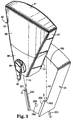
- Each of the side walls 45 and 47 include one of the channels 138 and 140. Referring to Figure 7, there is shown a bottom, rear portion of the side wall 47.
- the channels e.g. 140
- the channels are preferably located in the bottom, rear portion of a side wall (e.g. 47).
- the dispenser 30 preferably has surfaces which are substantially free of sudden discontinuities to afford ease of cleaning and to reduce the potential for accumulation of contaminants on the dispenser 30.
- the top 51, front 53, side 45 and 47 and bottom 49 walls of the container assembly 32 have surfaces which are substantially free of sudden discontinuities to afford ease of cleaning.
- the top, side and bottom walls of the bracket/actuator assembly 34 form a shape that is substantially identical to the shape of the container assembly 32 to provide a dispenser 30 which is substantially free of discontinuities.
- the shape of the dispenser 30 is not a complex geometry which contributes to the ease with which the dispenser 30 may be cleaned.
- the top 51 and front 53 walls have outer surfaces that are slightly curved while the side walls 45 and 47 are substantially flat.
- the front wall may have a radius of about six inches and the top wall 51 may have a radius of about six inches.
- the dispenser 30 is preferably relatively flat so that it presents a low profile which reduces the chances of it being inadvertently bumped, dislodged, or knocked over.
- the container assembly 32 is preferably relatively flat.
- the thickness of the container assembly 32 should be less than about two inches.
- the flanges 200 and 202 project inwardly from support arms 201 and 203.
- the container assembly 32 includes recessed ledges 139 and 141 adjacent the channels 138 and 140.
- the ledges 139 and 141 are recessed from the rest of the side walls 45 and 47 by an amount that is substantially the thickness of the support arms 201 and 203 so that there is a substantially flush interface or junction between the container assembly 32 and the bracket actuator assembly 34 to reduce the surfaces which may collect contaminants or which may be difficult to keep clean.
- the channels 138 and 140 each have first ends opening onto the bottom wall 49 and second ends detined by shoulder surfaces 143 and 145 which are adapted to engage stop surfaces S of the mounting flanges 200 and 202 and support arms 201 and 203. Engagement between the stop surfaces S and the shoulder surfaces 143 and 145 terminates the insertion of the container assembly 32 into the bracket/actuator assembly at the point where actuator 196 is properly oriented with the driven surfaces 164 of the piston 98.
- the container assembly 32 has a product path between the reservoir and the outlet 42.
- the container assembly 32 is disposable and the product path is located entirely within the container assembly 32 so that the entire product path is disposed of upon disposal of the container assembly 32. In this manner, the dispenser 30 avoids accumulation of contaminants within the product path.
- the container assembly 32 or portions thereof may be reusable.
- the container assembly 32 includes a valve assembly with inner surfaces which receive the piston 98 and define a pump chamber 90.
- the valve assembly includes outer surfaces 83 including sealing surfaces 84 for sealing the reservoir, grasping surfaces 40 (e.g. a knob) that are sized and shaped to be manually grasped, the outlet 42, and surfaces extending between the inner and outer surfaces 83 to define a fill hole 94.
- grasping surfaces 40 e.g. a knob
- the knob 40 can be turned to permit or prohibit flow of product (e.g. liquid) from the bottle 36 out through nozzle 42.
- the valve assembly is mounted within the dispenser 30 for movement between a sealed position ( Figure 2) with the sealing surfaces 84 sealing reservoir from the pump chamber 90, and a dispense position ( Figures 5 and 26-30) with the fill hole 94 affording passage of the product from the reservoir to the pump chamber 90.
- a sealed position Figure 2 with the sealing surfaces 84 sealing reservoir from the pump chamber 90
- a dispense position Figures 5 and 26-30
- the valve assembly provides a positive seal for the reservoir which is particularly convenient for shipping, handling or storage of the container assembly 32.
- the pump is a constant volume pump.
- the piston 98 is mounted within the inner surfaces of the valve assembly for movement between a return position ( Figure 26) and an actuated position ( Figure 29). Movement of the actuator 196 from the retracted to the extended position causes the actuator 196 to engage the surfaces 164 of the piston 98 and drive the piston 98 from the return position to the actuated position.
- a spring 100 is mounted within the inner surfaces of the valve assembly to bias the piston 98 toward the return position. The spring 100 also biases the actuator 196 toward the retracted position through the piston 98.
- the container assembly 32 includes a cover 38 that is adapted to receive the reservoir.
- the cover 38 has surfaces defining a passageway 46.
- the valve assembly comprises a spool element 52 ( Figures 17 and 18) adapted to be received in the passageway 46 of the cover 38.
- the spool element 52 is mounted to rotate within the passageway 46 between the sealed and dispense positions.
- the cover 38 includes a main opening 44 adapted to receive the bottle 36.
- the passageway 46 has a first end 48 and a second end 50 on opposite faces which receive the spool element 52.
- the axis of the passageway 46 in the cover 38 is conveniently oriented perpendicular to the main axis of the disposable container assembly 32.
- First 54 and second 56 hollow coaxial bosses project perpendicularly from the wall of the passageway 46 in the cover 38.
- the first hollow boss 54 includes a first opening 58 at the top and a second opening 60 into the passageway 46.
- the second hollow boss 56 includes an opening 62 at the top that is adapted to be connected to the bottle 36.
- the cover 38 may be constructed from any suitable material, such as, but not limits to high density polyethylene.
- the spool element 52 preferably includes a vent hole 96 which affords passage of replacement air into the reservoir.
- the vent hole 96 in the spool element 52 is a port for the aspiration of replacement air into the bottle 36.
- the reservoir includes a plug 64 having first 76 and second 78 passageways.
- the first passageway 76 affords passage of product from the reservoir to the pump chamber 90
- the second passageway 78 affords passage of replacement air into the reservoir.
- the plug 64 is constructed from an elastomeric material, but may include an insert 144( Figure 5).
- the majority of the plug 64 may be constructed from a thermoplastic elastomer such as Santoprene 271-64 available from Advanced Elastomer, and with the insert 144 constructed from high density polyethylene.
- the sealing surfaces 84 seal the first and second passageways 76 and 78, and in the dispense position, the fill hole 94 is aligned with the first passageway 76 and the vent hole 96 is aligned with the second passageway 78.
- the plug 64 is disposed between the bottle 36 and the cover 38.
- the plug 64 includes a conical top portion 66 that is adapted to seal against the inside surface of a neck portion 122 of the bottle 36, and a bottom portion 70 that is conveniently constructed to fit inside the first hollow boss 54 of the cover 38.
- the plug 64 also includes an intermediate flange 72 that is adapted to be compressed between the end of the bottle neck 122 and the top of the first hollow boss 54 in the cover 38.
- the bottom portion 70 of the plug 64 is constructed to include a cylindrical surface with a diameter substantially equal to that of the passageway 46 in the cover 38. When the plug 64 is compressed between the bottle 36 and the cover 38, the bottom surface 74 of the plug 64 projects slightly into the passageway 46 of the cover 38 and seals against spool element 52.
- the passageways 76 and 78 communicate between the interior of the bottle 36 and the spool element 52.
- the first passageway 76 includes a one-way valve 80 for preventing flow of product from the pump chamber 90 to the reservoir.
- the illustrated one-way valve 80 comprises a ball valve having a ball 146.
- the ball valve may be constructed from the insert mentioned above.
- the ball 146 is movable between an open position ( Figure 30) which affords passage of product from the reservoir to the pump chamber 90, and a closed position ( Figures 26-29) which prevents flow of product from the pump chamber 90 to the reservoir.
- the bottle 36 is situated above the outlet 42 when the dispenser 30 dispenses product, thus, gravity biases the ball 146 toward the closed position.
- the dispenser 30 is capable of completely dispensing substantially all of the product within the bottle 36, at least partly due to the location of the bottle 36 above the pump. Dispensing substantially all of the product within bottle 36 helps reduce wastage of product upon disposal of the container assembly 32.
- the second passageway 78 is adapted to provide a vent 82 for the entrainment of replacement air into the bottle 36.
- the piston 98 includes first and second piston seals 104 and 106 which are situated to seal the vent hole 96 when the piston 98 is in the return position, and to afford passage of ambient air through the vent hole 96, the second passageway 78, vent tube 82 and into the reservoir when the piston 98 is in the actuated position.
- the spool element 52 is adapted to closely fit in the passageway 46 of the cover 38 and includes a hollow cylindrical portion with a first end 86 that is adapted to connect to a retaining element 88 ( Figures 22 and 23), a second end that comprises the knob 40, and the pumping chamber 90.
- the retaining element 88 axially holds the spool element 52 in the passageway 46 of the cover 38 but permits rotation thereof.
- a solid portion (the sealing surfaces 84) of the hollow cylindrical portion of the spool element 52 seals against the elastomeric plug 64 and blocks the first 76 and second 78 passageways that communicate with the liquid in the bottle 36.
- the driven surfaces 164 of the piston 98 preferably do not project out beyond the rear wall 39 of the container assembly which helps reduce the chances of inadvertent or undesirable actuation of the container assembly during shipping, storage or handling prior to use.
- the inner cylindrical surface of the spool element 52 seals with piston 98.
- a boss 102 on the retaining element 88 holds the piston 98 in the spool element 52.
- the vent hole 96 in the spool element 52 is closed between first 104 and second 106 piston seal surfaces.
- product e.g. liquid
- the vent hole 96 is open to the atmosphere.
- the dispenser 30 preferably includes a drip resistant nozzle.
- the nozzle includes portions of the outlet tube 110 which includes the outlet 42, and a flexible, resilient member 112.
- the flexible, resilient member 112 has a seal portion 174 adapted to engage inner surfaces of the outlet tube 110 to seal the outlet 42 relative to the pump chamber 90.
- the flexible, resilient member 112 prevents air aspiration into the pump chamber 90 when the pump chamber 90 is filled with product (e.g. a liquid) from the reservoir.
- product e.g. a liquid
- the flexible, resilient member 112 also helps reduce the amount of unsealed liquid which is left adjacent the outlet 42 after a metered amount of the liquid is dispensed. This helps reduce contamination build up as there is less unsealed liquid adjacent the outlet 42 which may attract dirt, dust and other contaminants. Reducing the amount of unsealed liquid adjacent the outlet 42 diminishes the chance that dried liquid will clog or occlude the outlet 42 and also reduces the chance that any unsealed, undispensed liquid will drip from the outlet 42 at an inopportune time (e.g. between discharges of liquid).
- the flexible, resilient member 112 is mounted within the inner surfaces of the nozzle for movement between a) a relaxed position ( Figures 26 and 30) with the seal portion 174 engaging a portion of the inner surfaces of the nozzle to seal the outlet 42 relative to the pump chamber 90, b) a displaced sealing position ( Figures 27 and 29) in which the seal portion 174 is spaced from the relaxed position and in which the seal portion 174 engages a different portion of the inner surfaces of the nozzle to seal the outlet 42 relative to the pump chamber 90, and c) a deflected, dispense position (Figure 28) with the seal portion 174 of the flexible, resilient member 112 spaced from engagement with the inner surfaces of the nozzle to afford flow of the product to be dispensed from the pump chamber 90 through the outlet 42. Movement of the flexible resilient member 112 from the deflected, dispense position (Figure 28) toward said relaxed position ( Figure 29) tends to urge the unsealed, undispensed product from the outlet 42 back into
- a relaxed shape of the flexible, resilient member 112 is shown in Figures 21 and 26.
- the flexible, resilient member 112 is elongate in an axial direction and includes a seating portion having a first end 168 and retaining surfaces 172 spaced from the first end 168.
- the flexible resilient member 112 is preferably physically displaced to a different location within the nozzle without being deformed or deflected from its relaxed shape.
- the flexible resilient member 112 preferably stretches axially to deform from its relaxed shape.
- the inner surfaces of the nozzle include a base surface 173 for receiving the first end 168 of the flexible, resilient member 112 in the relaxed position ( Figures 26 and 30), and a stop surface 175 which is spaced from the base surface 173 to afford displacement of the flexible resilient member 112 from the relaxed position to the displaced sealing position by pressure within the pump chamber 90.
- the surfaces 173 and 175 may be spaced from each other about 0.19 inches.
- the seating portion of the member 112 may be fixed relative to the nozzle so that pressure within the pump chamber 90 deflects the flexible resilient member 112 from the relaxed position to the displaced sealing position.
- the inner surfaces of the outlet tube 110 of the nozzle are elongate in an axial direction and have a cross section along the axis.
- the cross section of the inner surface 118 of the outlet tube 110 which is immediately adjacent the sealing portion 174 of the flexible, resilient member 112 in the displaced, sealing position (Figure 27) is smaller than the cross section of the inner surface 119 of the outlet tube 110 which is immediately adjacent the sealing portion 174 of the flexible, resilient member 112 in the deflected, dispense position ( Figure 28).
- the inner surface 118 comprises a cylindrical portion having a substantially constant cross-sectional diameter (e.g. about 0.25 inches).
- the cylindrical portion is adapted to engage the sealing portion 174 of the flexible, resilient member 112 in the relaxed position ( Figures 26 and 30) and the displaced, sealing position ( Figures 27 and 29).
- the inner surfaces 119 include an enlarged portion (e.g. tapering out to a diameter of about 0.29 inches) substantially adjacent the cylindrical portion 118.
- the seating portion of the member 112 has a cross sectional area along its axis, and a central shaft portion 170 between the seating portion and the sealing portion 174.
- the central shaft portion 170 has a cross sectional area along the axis.
- the sealing portion 174 of the flexible resilient member 112 comprises a substantially cylindrical surface having a diameter defining a cross sectional area along the axis.
- the cross sectional area of the central shaft portion 170 is substantially less than the cross sectional areas of both the seating portion and the sealing portion 174 to afford axial stretching of the flexible, resilient member 112.
- the seating portion of the member 112 is capable of being snapped through a partition in the outlet tube 110 during assembly of the container assembly 32.
- the seating portion may be cylindrical with a maximum outer diameter of about 0.22 inches and a thickness of about 0.12 inches; the central shaft portion may be cylindrical with a diameter of about 0.125 inches and a length of less than about 1 inch, and the sealing portion may be frusto-conical with a maximum diameter of about 0.26 inches with a taper of about forty five degrees relative to its longitudinal axis.
- the flexible, resilient member 112 is first axially displaced and then stretched. In the deflected dispense position of the member 112, an annular flow path is opened between the seal portion 174 and the inner surface 119 of the outlet tube 110. At approximately the time when liquid stops flowing from the pump chamber 90 through the outlet 42, the member 112 relaxes from the deflected, dispense position to its relaxed shape in the displaced, sealing position and circumferentially seals.
- the member 112 is axially retracted until the first end 168 of the seating portion abuts the base surface 173 of the inner surface of the nozzle. The axial retraction of the sealing portion 174 after it circumferentially seals against the inner surfaces of the nozzle causes any liquid remaining within the nozzle adjacent outlet 42 to be drawn back into the nozzle and away from the outlet 42.
- liquid in the pump chamber 90 flows through a port 108 into the outlet tube 110 in the knob 40.
- the member 112 controls the direction of flow and helps reduce the amount of unsealed liquid that remains adjacent the outlet 42 that could dry between uses and obstruct the outlet 42.
- the outlet 42 is preferably provided by an insert 41 that is connected to the distal end of the outlet tube 110 by means of a snap fit, although gluing, staking, or ultrasonic welding could also be used to make the connection.
- the bottle 36 includes a body portion 120 and neck portion 122 that is adapted to connect to the cover 38.
- the neck portion 122 of the bottle is adapted to connect to cover 38 by any convenient means; threads are one possibility, or as in the depicted embodiment, the neck portion 122 of the bottle 36 includes an externally projecting lip 124 that connects to cover 38 by means of a snap fit.
- the bottle 36 includes a non-circular region 126 that is recessed from the body portion 120. The recessed region 126 is adapted to extend into the cover 38 to prevent rotation of the bottle 36 after assembly with the cover 38.
- the bottle 36 can be fabricated from any material compatible with the product to be dispensed.
- the bottle 36 is fabricated from a blow molded thermoplastic such as, but not limited to high density polyethylene.
- the entire bottle 36 or a portion thereof may be constructed from a transparent or semi-transparent material so that the user may visually determine the amount of product (liquid) that remains in the reservoir.
- the cover 38 is seen in isolation.
- the cover 38 includes an exterior body portion with a main opening 44 adapted to receive bottle 36 (not shown in these views for clarity).
- the main opening 44 is sized and shaped to receive the recessed region 126 on the bottle 36 ( Figure 10) such that the junction between the bottle 36 and the cover 38 is essentially flush.
- a passageway 46 runs substantially perpendicular to the main axis of the bottle 36, and there is an orifice 130 in the passageway 46 that is substantially parallel to the main axis of the bottle 36.
- the passageway 46 extends completely through the cover 38 and is bounded by a first end 48 on the front face and a second end 50 on the back face.
- the first 48 and second 50 ends are surrounded by first 132 and second 134 countersunk regions.
- the first countersunk region 132 optionally includes projections 137 that function as a detent or to limit the rotation of the spool element 52.
- the second countersunk region 134 is adapted to receive retaining element 88.
- the cover 38 includes first 54 and second 56 hollow coaxial bosses that project perpendicularly from the passageway 46.
- the first inner boss 54 surrounds the orifice 130 in the wall of the passageway 46 and is adapted to retain the bottom portion of the plug 64.
- the top of the first boss 54 is adapted to seat against a flange 72 on the plug 64 and control the distance that the bottom surface of the plug 64 projects into the passageway 46.
- the second boss 56 connects to the bottle 36 by any convenient means; in the depicted embodiment, the second boss 56 includes an inwardly projecting lip 136 that connects with the externally projecting lip 124 on the bottle 36 by means of a snap fit.
- the second boss 56 can be continuous or can be slotted so as to control the assembly force of the snap fit joint.
- the plug 64 is seen in isolation.
- the plug 64 includes a top conical portion 66 adapted to seal against the inside of the bottle neck 122, and a bottom portion 70 adapted to fit inside the first boss 54 in the cover 38.
- the bottom surface 74 is adapted to seal against the spool element 52, and an outwardly projecting flange 72 is adapted to seal between the end of the bottle neck 122 and the top of the first boss 54.
- the plug 64 includes a outwardly projecting annular rib ( Figures 15 and 16) that is intended to improve the seal between the top conical portion 66 and the inside of the bottle neck 122.
- the one-way valve 80 inserted within first passageway 76 can be of any of several well known types, including valves integrally molded in the elastomeric plug. As depicted in Figure 5, the presently preferred valve 80 includes valve seat insert 144 and the valve includes a gravity-biased ball 146 or poppet. Alternatively the valve 80 could be a spring-biased ball or poppet sealing against an integral valve seat in the plug 64.
- the second passageway 78 in the plug 64 retains a first end of a vent tube 82.
- the second end of the vent tube 82 is above the normal liquid level in the bottle when the disposable container assembly 32 is mounted in an inverted position on the bracket/actuator 34.
- Portions of the plug 64 can be fabricated from any elastomeric material that is compatible with the product to be dispensed. This is can be accomplished by molding from a thermoset elastomer.
- the portions of the plug shown in Figure 16 may be injection molded from thermoplastic elastomers (e.g. Santoprene 271-64) with a hardness of 40 to 90 Shore A.
- the spool element 52 is adapted to connect to a retaining element 88.
- the second end of the spool element 52 is shaped as a knob 40 that integrally includes outlet tube 110.
- the spool 52 includes two externally projecting ribs 148 and 150 that seal with the passageway 46 in the cover 38 by means of an interference fit.
- the first end 86 of the spool element 52 is adapted to be axially retained in the cover 38 by any convenient means.
- the first end 86 of the spool element 52 includes an externally projecting lip 152 that engages a snap fit joint on retaining element 88, but other expedients such as a threaded retainer or a split ring retainer could be used.
- the pump chamber 90 is open at first end 86 and is in part defined by the inner surfaces of the knob 40 at the other end.
- the pump chamber 90 contains the piston 98 and the piston return spring 100.
- a shoulder 154 in the pump chamber 90 acts as a piston stop.
- the knob 40 includes a flange 156 adapted for grasping by the hand of a user.
- the flange 156 of the knob 40 can include projections 158 adapted to limit the rotation of the spool element 52 in the cover 38.
- the valve assembly rotates approximately one-hundred twenty (120) degrees between the sealed and dispense positions.
- the piston 98 is seen in isolation.
- the piston 98 slidably seals in the pump chamber 90 and includes a rod portion 162.
- the piston 98 preferably includes multiple piston seals 104 and 106 but could optionally include a single sealing surface.
- the vent hole 96 in the spool element 52 is blocked between the two piston surfaces 104 and 106 in the return position of the piston 98.
- the two piston surfaces 104 and 106 are supported from the rod portion by any convenient structure.
- the driven surface 164 transmits the force from an actuator 196 in the bracket/actuator assembly 34 as will be explained with more particularity below.
- the second end 166 of the rod portion 162 retains the piston return spring 100.
- the piston 98 can be fabricated from any material compatible with the liquid to be dispensed; in the presently preferred embodiment, the piston 98 is injection molded from a thermoplastic material, such as, but not limited to high density polyethylene (HDPE).
- HDPE high density polyethylene
- the retaining element 88 connects to the spool element 52 to axially hold the spool element 52 in the cover 38 and to retain the piston 98 in the spool element 52 in the normal spring-biased (return) position.
- a number of expedients for retaining the spool element 52 may be used, such as a threaded retainer or a split ring retainer.
- the retaining element 88 includes three concentric bosses projecting from a cylindrical disc portion 176.
- the first central boss 178 fits inside the spool element 52.
- the top surface 180 of the first boss 178 retains the piston 98 in the return position.
- An axial bore 182 in the first boss 178 functions as a bushing for the piston 98 and the reciprocating actuator 196 of the bracket/actuator assembly 34.
- the second middle boss 184 includes projections 186 that connect to the first end 86 of the spool element 52 by means of a snap fit.
- the third outer boss 188 includes multiple, inwardly projecting, cantilevered beams 190 that axially bias the spool element 52 against the cover 38.
- the retaining element 88 is injection molded from a thermoplastic material, such as high density polyethylene.
- the bracket/actuator assembly 34 includes a housing 191 including a front housing 192 and a rear housing 194. Mounted within the two housings are the actuator 196 and a means 198 to drive the actuator 196.
- the front and rear housings 192 and 194 can be fabricated in any convenient shape, although it is desirable to provide a exterior surface with simple planar projections as depicted so as to make the bracket/actuator assembly 34 easy to clean.
- the bracket/actuator assembly 34 is formed from a plastic material in a shape visually similar to the disposable container assembly 32.
- the front housing 192 includes a passageway 208 that serves as a bushing for the actuator 196.
- the means 198 for moving the actuator 196 conveniently includes a cavity 210 in the rear housing 194 in which the actuator can slide forwards and back.
- An air chamber 212 disposed behind the cavity 210 is in fluid communication with the hose 221 which allows the air chamber to be pressurized.
- the actuator 196 is moved forward and against the driven surface 164 of the piston 98.
- the piston return spring 100 in the container assembly 32 helps return the actuator when the air chamber 212 is depressurized.
- An actuator seal 216 is provided to prevent leakage of air from the air cavity past the actuator 196.
- the seal 216 can include any well known devices such as o-rings, v-rings, u-seals, diaphragms, and rolling diaphragms.
- the actuator 196 can be reciprocated by any of several well known means including mechanically, for example a mechanical linkage to a user operated lever; electromechanically, for example a motor and a lead screw; or hydraulically, for example a fluid actuator.
- the various parts of the container assembly 32 may injection molded from a thermoplastic material.
- the spool element 52 can be fabricated from any material compatible with the liquid to be dispensed.
- the spool element 52 is injection molded from a thermoplastic material, such as, but not limited to high density polyethylene.
- the flexible, resilient member 112 can be fabricated from any elastomeric material compatible with the product to be dispensed.
- the flexible, resilient member 112 is molded from a compatible elastomer by well known processes; conveniently, the member 112 is injection molded from a thermoplastic elastomer.
- the member 112 may be constructed from a thermoplastic elastomer, such as, but not limited to Santoprene 271-64 available from Advanced Elastomer Systems.
- Set up of the dispenser 30 may begin with attaching the bracket/actuator assembly 34 in a convenient location, such as on the wall by a sink or on a wheel mounted vertical pole (not shown).
- the foot actuated pneumatic bladder pump 220 is coupled to the bracket/actuator assembly 34 with the air hose 221 through port 214.
- the container assembly 32 may then be attached to the bracket/actuator assembly 34 in the manner shown in Figure 3, except that typically the valve assembly will be in the sealed position (as opposed to the dispense position shown in Figure 3) during attachment of the container assembly 32 to the bracket/actuator assembly 34.
- the rear wall 39 of the container assembly 32 is placed opposite the front housing 192 of the bracket/actuator assembly 34 and the container assembly is moved in a substantially vertically downward direction 10 until the flanges 200 and 202 engage the channels 138 and 140.
- the flanges 200 and 202 and channels 138 and 140 are situated to automatically guide the driven surfaces 164 of the piston 98 to a position opposite the actuator 196. Engagement between the stop surfaces S and the shoulder surfaces 143 and 145 limits the insertion of the container assembly 32 into the bracket/actuator assembly 34 at the point where the piston 98 is properly oriented relative to the actuator 196.
- the valve assembly should be moved from the sealed position ( Figure 2) to the dispense position ( Figure 1).
- the outlet 42 opens substantially vertically downward.
- the user now steps on the foot actuated pneumatic bladder 220 which causes the actuator 196 to move from the retracted ( Figure 25 solid lines) position to the extended position ( Figure 25 dashed lines). Movement of the actuator from the retracted to the extended position causes the distal end of the actuator 196 to engage the driven surfaces 164 of the piston 98 and drives the piston from the return position to the actuated position.
- FIGS 26 through 30 sequentially illustrate movement of the piston 98 from the return to actuated position and back to the return position.
- the actuator 198 is omitted from these views to emphasize other details.
- the piston 98 is biased to the return position by spring 100.
- the vent tube 82 and hole 96 are sealed from atmospheric air by piston seal surface 106.
- the pump chamber 90 is full of a precise, metered amount of product to be dispensed, regardless of the amount of product in the reservoir.
- the pump chamber 90 is sealed by the piston seal surfaces 104 and 106 and the flexible, resilient member 112 in the relied position. Because the ball 146 of the ball valve is in a down, closed position, product from the pump chamber 90 cannot travel from the pump chamber 90 back into the reservoir via first passageway 76.
- the arrow in Figure 27 illustrates the direction of movement of the piston 98.
- the piston 98 is shown just as it moves from the return toward the actuated position.
- pressure within the pump chamber 90 increases and causes the flexible, resilient member 112 to be initially displaced from its relaxed position in Figure 26 to a displaced, sealing position ( Figure 27). While the flexible resilient member 112 still seals the pump chamber 90 when it is in the displaced, sealing position, it seals with a different portion of the inner surface 118 than it does when it is in the relaxed position.
- the dispenser has not yet dispensed product.
- Figure 28 illustrates the piston 98 after it has moved further along its stroke toward the actuated position.
- the flexible, resilient member 112 stretches axially to a deflected, dispense position which affords dispensing of the product from pump chamber 90 through the outlet 42.
- the axial stretching of the member 112 opens an annular path for the product to flow from the pump chamber 90, past the sealing portion 174 of the member 112 and past the inner surface 119 which is just adjacent the sealing portion 174 when the member 112 is in the deflected, dispense position.
- Figure 29 illustrates the piston 98 in the actuated position.
- Figure 30 illustrates the piston 98 as it is being spring biased from the actuated position back to the return position.
- a partial vacuum is created in the pump chamber.
- Vacuum in the pump chamber 90 causes the flexible, resilient member 112 to move from the displaced sealing position (Figure 29) back to the relaxed position ( Figure 30).
- the movement of the member 112 from the displaced sealing position ( Figure 29) back to the relaxed position ( Figure 30) changes the unsealed volume within tube 110 that is substantially adjacent the outlet 42.
- the unsealed volume adjacent outlet 42 is increased which tends to draw product from the outlet 42 back within outlet tube 110 which helps reduce the chance that the outlet 42 will drip at an inopportune time.
- the outlet 42 is formed by insert 41 which provides a restriction substantially adjacent the outlet 41 to enhance the effectiveness of the flexible, resilient member 112 at preventing drips.
- the vacuum also causes the ball 146 of the ball valve to move upward to an open position which affords flow of product from the reservoir, through first passageway 76 and into the pump chamber 90.
- the direction of the piston 98 is also illustrated in Figure 30 with an arrow.
- Piston seal 106 has already sealed vent hole 96 and vent tube 82.
- the entire container assembly 32 When the product within the reservoir is depleted, the entire container assembly 32 may be disposed of which reduces the chance of contaminant build up within the dispenser 30.
- a refill container assembly may be attached to bracket/actuated assembly 34 and the process repeated.
- product with the reservoir may be simply be replenished (or a new, full bottle 36 may be supplied for the container assembly 32) and the other elements of the container assembly (e.g. the pump and valve assembly) may be reused.
Abstract
Description
- The present invention relates generally to product dispensers, and more particularly to liquid or fluid dispensers specially adapted to dispense cleansing, disinfecting or sterilizing products such as antiseptic soaps, hydroalcoholic solutions, disinfecting lotions, cleaning solutions and other antimicrobial liquids.
- In food processing establishments, surgical centers, physician and dental offices, hospitals and other healthcare facilities, contamination of objects (e.g. hands) with infectious or other deleterious materials is a significant problem. The use of a contaminated object (e.g. a surgeon's hand) in such environments can be a serious problem.
- To address the problems associated with the spread of bacteria and microorganisms, the art has developed a variety of dispensers adapted to provide products for cleaning, disinfecting and potentially even sterilizing objects. For example, antiseptic preparation of a surgeon's hands conventionally includes a prolonged hand and lower arm scrubbing with an antimicrobial soap. The antimicrobial soap is typically dispensed from a liquid soap dispenser mounted near a scrub sink. To resist contamination, antimicrobial soap dispensers are designed to be operated without hand contact by mechanical, pneumatic or electromechanical means.
- The contamination problem extends not just to the objects to be cleaned but to the external and internal portions of dispensers themselves. Contamination accumulation over time is a problem to be addressed for each object left in a room over time. U.S. Patent No. 3,203,597 discloses a surgical soap dispenser which includes a complex bracket/actuator assembly and a bottle/pump assembly. The entire fluid (soap) path is provided in the bottle/pump assembly. The bottle/pump assembly is disposable in order to resist contamination build up in the fluid path. However, the bracket/actuator assembly is intended to be reusable and must itself be cleaned and disinfected. The bracket/actuator assembly comprises a complex structure including keyways and cam surfaces. This complex structure may tend to collect debris and make it very difficult to clean.
- Set up and maintenance of a dispenser are also affected by the contamination problem. Dispensers which require excessive handling during set up or maintenance increase the risk of contamination by the person preparing or maintaining the dispenser. For example, refillable bottles of soap with a threaded cap structure require personnel to rotate the cap relative to the rest of the dispenser for several revolutions. U.S. Patent Nos. 4,667,854; 4,921,131; 4,946,070; 4,946,072l and 5,156,300 disclose various dispensers which appear more difficult to set up and maintain than the present invention. Those patents disclose dispensers which include doors, flaps or covers which are opened and closed. Some of those dispensers include refill elements which are carefully placed in position to avoid dispenser malfunction. In U.S. Patent No. 3,203,597, the entire refill bottle must be rotated ninety degrees so that a flange on a piston may be received in a slot in an actuator assembly. Dispensers which are complicated to set up or maintain increase the risk of improper set up due to operator error with the attendant risk of unsatisfactory dispenser performance or malfunction.
- Problems are also associated with the storage, transportation, handling and shipping of prior art dispensers which include valve and pump means. For example, in U.S. Patent No. 3,203,597, a pump mechanism projects from the end of a soap container. Care needs to be taken that the pump mechanism is not inadvertently actuated during storage, transportation, handling and shipping of the soap container. The art has developed articles such as caps and removable inserts which are designed to prevent inadvertent actuation of the dispenser prior to use by the intended user. However, these additional articles tend to complicate set up of the dispenser and may also add cost to the dispenser.
- According to the present invention there is provided a container assembly for a product dispenser which (1) affords quick, convenient set up, refill and maintenance without requiring excessive user handling, (2) is easily cleaned, (3) reduces opportunities for contamination build up in its product path, (4) may optionally provide precise, repeatable metered amounts of product, regardless of the volume of product in a reservoir, (5) has a low profile, (6) optionally includes a novel nozzle for reducing dripping, waste, drying and clogging, (7) may be actuated without hand contact to avoid contamination due to actuation, and (8) includes container and bracket/actuator assemblies and an attachment mechanism which automatically aligns elements of the container and bracket/actuator assemblies without the need for excessive handling.
- According to the present invention, there is provided a container assembly that is attachable to a bracket/actuator assembly. The bracket/actuator assembly has a movable actuator and a pair of mounting flanges. The actuator is movable between a retracted position which affords attachment of the container assembly to the bracket/actuator assembly and an extended position that is spaced from the retracted position. The container assembly comprises a reservoir for holding product to be dispensed, an outlet sized and shaped to afford passage of product to be dispensed, and a pump that is operatively associated with the actuator. The pump includes a driven surface for receiving the actuator. The driven surface is adapted to be driven by the actuator when the actuator moves from the retracted to the extended position.
- The container assembly also includes a pair of channels which are sized and shaped to cooperatively receive the mounting flanges of the bracket/actuator assembly to attach the container assembly to the bracket/actuator assembly and to align the driven surface of the pump with the actuator when the container assembly is attached to the bracket/actuator assembly. The container assembly is attachable to the bracket/actuator assembly in a vertically downward direction. The channels of the bracket/actuator assembly are elongate and situated so that they taper toward each other in the direction of attachment so that the driven surface of the pump is guided into a predetermined orientation relative to the actuator upon attachment of the container assembly to the bracket/actuator assembly.
- The container assembly includes a valve assembly having inner surfaces. The inner surfaces receive the pump and define a pump chamber. The valve assembly also has outer surfaces including sealing surfaces for sealing the reservoir, and grasping surfaces that are sized and shaped to be manually grasped. The valve assembly also includes the outlet. Surfaces extend between the inner and outer surfaces to define a fill hole for the pump chamber. The valve assembly is adapted to move between a sealed position with the sealing surfaces sealing the pump chamber from the reservoir, and a dispense position with the fill hole affording passage of the product from the reservoir to the pump chamber.
- Alternatively, the present invention may be viewed as a unique method of dispensing product.
- Preferred embodiments of the present invention are listed in the following:
- 1. A container assembly attachable to a bracket/actuator assembly having a
movable actuator and a pair of mounting flanges; said container assembly comprising:
- a reservoir for holding product to be dispensed,
- an outlet sized and shaped to afford passage of product to be dispensed;
- a pump, operatively associated with the actuator, for pumping the product through the outlet, the pump including a driven surface for receiving the actuator;
- a pair of channels which are sized and shaped to cooperatively receive the
mounting flanges of the bracket/actuator assembly to attach the container assembly to
the bracket/actuator assembly and to align the driven surface of the pump with the
actuator when the container assembly is attached to the bracket/actuator assembly;
wherein the container assembly is attachable to the bracket/actuator assembly in a vertically downward direction; and - the channels are elongate and situated so that they taper toward each other in the direction of attachment so that the driven surface of the pump is guided into a predetermined orientation relative to the actuator upon attachment of the container assembly to the bracket/actuator assembly.
- 2. A container assembly according to embodiment 1 wherein the container assembly includes a substantially planar rear wall adapted to abut the bracket/actuator assembly when the container assembly is attached to the bracket/actuator assembly.
- 3. A container assembly according to embodiment 1 wherein the container assembly includes top, front, and side walls with surfaces which are substantially free of sudden discontinuities to afford ease of cleaning.
- 4. A container assembly according to embodiment 1 wherein the container assembly
includes a valve assembly that includes said outlet, and
wherein said valve assembly is movable relative to the reservoir between a first position which seals the product within said reservoir and a second position which affords dispensing of product through the outlet. - 5. A container assembly according to embodiment 4 wherein said valve assembly is adapted to rotate between said first and second positions.
- 6. A container assembly according to embodiment 4 wherein said reservoir has a vertical axis, said valve assembly is elongate along an axis which is perpendicular to the vertical axis of the reservoir.
- 7. A container assembly according to embodiment 6 wherein said valve assembly is adapted to rotate approximately one hundred twenty degrees between said first and second positions; and wherein, in said second position, said outlet opens downwardly.
- 8. A container assembly according to embodiment 1 wherein the container assembly is disposable and includes a product path between the reservoir and the outlet, and said product path is located entirely within said container assembly so that the entire product path is disposed of upon disposal of the container assembly.
- 9. A container assembly according to embodiment 1 wherein said container assembly includes a pair of side walls which taper toward each other in the direction of attachment, and said side walls each include one of said channels.
- 10. A container assembly according to embodiment 9 wherein said side walls have bottom, rear portions and said channels are located in the bottom, rear portions of said side walls.
- 11. A container assembly according to embodiment 9 wherein the container assembly
includes a bottom wall, and
- said channels have a first end opening onto the bottom wall and a second end defined by a shoulder surface which is adapted to engage a stop surface of the bracket/actuator assembly.
- 12. A method of using a disposable container assembly which is attachable to a
bracket/actuator assembly having a movable actuator and a pair of mounting flanges;
the method comprising the steps of:
- a) providing a container assembly including: a reservoir for holding product to be dispensed, an outlet sized and shaped to afford passage of product to be dispensed; a pump, operatively associated with the actuator, for pumping the product through the outlet, the pump including a driven surface for receiving the actuator; a pair of channels which taper toward each other and which are sized and shaped to cooperatively receive the mounting flanges of the bracket/actuator assembly; and
- b) attaching the container assembly to the bracket/actuator assembly and substantially simultaneously aligning the driven surface of the pump with the actuator by moving the container assembly in a substantially vertically downward direction relative to the bracket/actuator assembly until the channels engage the mounting flanges.
- 13. A method of using a disposable container assembly according to embodiment 12
wherein the step of providing a container assembly includes the step of providing a
valve assembly that includes said outlet, and the valve assembly is adapted to move
relative to the reservoir between a first position which seals the product within said
reservoir and a second position which affords dispensing of product through the outlet;
and
- the method further comprises the step of moving the valve assembly from said first position to said second position.
- 14. A method of using a disposable container assembly according to
embodiment 13 wherein the step of moving the valve assembly includes the step of rotating the valve assembly from said first to said second position. - 15. A method of using a disposable container assembly according to
embodiment 14 wherein the step of rotating the valve assembly includes the step of rotating the valve assembly approximately on hundred and twenty degrees between said first and second positions, such that, in the second position, the outlet opens downwardly. - 16. A method of using a disposable container assembly according to embodiment 12
wherein the step of providing a container assembly comprises the step of providing a
disposable container assembly with a product path between the reservoir and the outlet
which is located entirely within the container assembly; and
- the method further includes the step of disposing of the entire product path upon depletion of the container assembly.
- 17. A dispenser for product comprising:
- a bracket/actuator assembly having a movable actuator and a pair of mounting flanges;
- a container assembly comprising:
- a reservoir for holding the product to be dispensed,
- an outlet sized and shaped to afford passage of product to be dispensed;
- a pump, operatively associated with the actuator, for pumping the product through the outlet, the pump including a driven surface for receiving the actuator;
- attachment and alignment means for attaching the container assembly to the
bracket/actuator assembly and for automatically aligning the driven surface of the
pump with the actuator during attachment of the container assembly to the
bracket/actuator assembly; wherein said attachment and alignment means comprises a
pair of inwardly directed flanges on one of said bracket/actuator and container
assemblies and surfaces for engaging said flanges on the other of said assemblies; and
wherein the attachment and alignment means affords attachment of said container assembly to the bracket/actuator assembly in a vertically downward direction. - 18. A dispenser according to embodiment 17 wherein the dispenser includes top, front, and side walls with surfaces which are substantially free of sudden discontinuities to afford ease of cleaning.
- 19. A dispenser according to embodiment 17 wherein the container assembly is disposable and includes a product path between the reservoir and the outlet, and said product path is located entirely within said container assembly so that the entire product path is disposed of upon disposal of the container assembly.
- 20. A dispenser according to embodiment 17 wherein said container assembly includes a pair of side walls which taper toward each other in the direction of attachment, and said side walls each include one of said surfaces for engaging said flanges.
- 21. A dispenser according to
embodiment 20 wherein the flanges of the bracket/actuator assembly include a stop surface; - the container assembly has a bottom wall, and the surfaces for engaging said flanges have a first end opening onto the bottom wall and a second end defined by a shoulder surface which is adapted to engage said stop surfaces of the bracket/actuator assembly when the container assembly is attached to the bracket/actuator assembly.
- 22. A container assembly attachable to a bracket/actuator assembly having an
actuator movable between a retracted position which affords attachment of the
container assembly to the bracket/actuator assembly and an extended position spaced
from the retracted position; said container assembly comprising:
- a reservoir for holding product to be dispensed,
- a pump for pumping the product, the pump including a driven surface for receiving the actuator and being driven by the actuator when the actuator moves from the retracted to the extended position;
- a valve assembly having inner surfaces adapted to receive the pump and to
define a pump chamber, outer surfaces including sealing surfaces for sealing the
reservoir, grasping surfaces that are sized and shaped to be manually grasped, an outlet
sized and shaped to afford passage of product to be dispensed; and surfaces extending
between said inner and outer surfaces to define a fill hole; and
wherein the valve assembly is movable between a sealed position with the sealing surfaces sealing the pump chamber from the reservoir, and a dispense position with the fill hole affording passage of the product from the reservoir to the pump chamber. - 23. A container assembly according to embodiment 22 wherein said pump comprises a
piston mounted within the inner surfaces of said valve assembly for movement between
a return position and an actuated position, said driven surface comprises surfaces on
said piston which are used and shaped to receive the actuator; and
wherein movement of said actuator from said retracted to said extended position causes said actuator to engage the driven surfaces of said piston and drive said piston from said return position to said actuated position. - 24. A container assembly according to
embodiment 23 further including a spring mounted within the inner surfaces of the valve assembly for biasing the piston toward said return position. - 25. A container assembly according to embodiment 22 further including a cover
adapted to receive the reservoir, and having surfaces defining a passageway;
- said valve assembly comprises a spool element adapted to be received in the passageway of the cover; and
- the spool element rotates between said sealed and dispense positions.
- 26. A container assembly according to embodiment 25 wherein said spool element
includes a vent hole affording passage of replacement air into the reservoir;
- said reservoir includes a plug having first and second passageways; said first
passageway affording passage of product from said reservoir to said pump chamber,
and said second passageway affording passage of replacement air into the reservoir;
and
wherein, in the sealed position, said sealing surfaces seal said first and second passageways, and in said dispense position, said fill hole is aligned with said first passageway and said vent hole is aligned with said second passageway. - 27. A container assembly according to embodiment 26 wherein said first passageway includes a one-way valve for preventing flow of product from said pump chamber to said reservoir.
- 28. A container assembly according to embodiment 26 wherein the one-way valve
comprises a ball valve having a ball, said ball being movable between an open position
which affords passage of product from the reservoir to said pump chamber, and a
closed position which prevents flow of product from the pump chamber to said
reservoir; and
wherein, gravity biases said ball toward said closed position. - 29. A container according to embodiment 26 wherein said pump means comprises a
piston mounted within the inner surfaces of said valve assembly for movement between
a return position and an actuated position, said driven surface comprises driven
surfaces on said piston which are sized and shaped to receive the actuator;
wherein movement of said actuator from said retracted to said extended position causes said actuator to engage the driven surfaces of said piston and drive said piston from said return position to said actuated position; and - said piston includes first and second piston seals situated to seal said vent hole when said piston is in said return position, and to afford passage of ambient through said vent hole, said second passageway and into the reservoir when said piston is in said actuated position.
- 30. A container assembly according to embodiment 22 wherein said grasping surfaces comprise a knob having an outlet tube therein, said outlet tube having said outlet.
- 31. A method of using a container assembly that is attachable to a
bracket/actuator assembly having an actuator movable between a retracted position
which affords attachment of the container assembly to the bracket/actuator assembly
and an extended position spaced from the retracted position; the method comprising
the steps of:
- a) providing the container assembly including a reservoir for holding product to be dispensed, a pump for pumping the product, the pump including a driven surface for receiving the actuator and being driven by the actuator when the actuator moves from the retracted to the extended position; a valve assembly having inner surfaces adapted to receive the pump and to define a pump chamber, outer surfaces including sealing surfaces for sealing the reservoir, grasping surfaces that are sized and shaped to be manually grasped, a outlet sized and shaped to afford passage of product to be dispensed; an surfaces extending between said inner and outer surfaces to define a fill hole;
- b) moving the valve assembly between a sealed position with the sealing surfaces sealing the pump chamber from the reservoir, and a dispense position with the fill hole affording passage of the product from the reservoir to the pump chamber;
- c) attaching the container assembly to the bracket/actuator assembly; and
- d) moving the valve assembly from the sealed position to the dispense position.
- 32. A method according to embodiment 31 wherein the step of moving the valve assembly from the sealed position to the dispense position includes the step of rotating the valve assembly from the sealed position to the dispense position.
-
- The present invention will be further described with reference to the accompanying drawing wherein like reference numerals refer to like parts in the several views, and wherein:
- Figure 1 is a perspective view of a container assembly attached to a bracket/actuator assembly, with a foot actuated pneumatic bladder pump shown in phantom lines;
- Figure 2 is a front view of the container and bracket/actuator assemblies of Figure 1 with the foot actuated pneumatic bladder pump omitted and with a valve assembly shown in a sealed position;
- Figure 3 is a perspective view of the container assembly separated from the bracket/actuator assembly which illustrates the direction of attachment of the container assembly onto the bracket assembly;
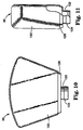
- Figure 4 is a tight side view of the container and bracket/actuator assemblies shown in Figure 2, with the valve assembly shown in a dispense position;
- Figure 5 is a sectional view of the container assembly;
- Figure 6 is a tight side view of Figure 2, with the bracket/actuator assembly omitted to illustrate details of the container assembly;
- Figure 7 is a perspective view of a portion of the container assembly;
- Figure 8 is a bottom view of the container assembly;
- Figure 9 is a rear view of the container assembly;
- Figure 10 is a front view of a reservoir for holding product to be dispensed which forms a portion of the container assembly;
- Figure 11 is a side view of the reservoir of Figure 10;
- Figure 12 is a top view of a cover which forms a portion of the container assembly;
- Figure 13 is a cross-section view of the cover taken substantially along section lines 13-13 in Figure 12;
- Figure 14 is a cross-section view of the cover taken substantially along section lines 14-14 in Figure 12;
- Figure 15 is a perspective view of a plug which forms a portion of the container assembly;
- Figure 16 is a cross-section view of the plug of Figure 15 taken substantially along section lines 16-16 in Figure 15, with an insert removed to illustrate other details of the plug;
- Figure 17 is a perspective view of a spool element for use in the container assembly;
- Figure 18 is a cross-section view of the spool element of Figure 17 taken substantially along section lines 18-18 in Figure 17;
- Figure 19 is a side view of a piston for use in a pump in the container assembly;
- Figure 20 is a cross-section view of the piston of Figure 19 taken substantially along section lines 20-20 in Figure 19;
- Figure 21 is a side view of a flexible, resilient member for use in the container assembly;
- Figure 22 is a perspective view of a retaining element for use in the container assembly;
- Figure 23 is a cross-section view of the retaining element of Figure 22 taken along section lines 23-23 in Figure 22;
- Figure 24 is a front view of the bracket/actuator assembly of Figure 1 with the container assembly and foot actuated pneumatic bladder pump omitted;
- Figure 25 is a side view of the bracket/actuator assembly of Figure 24 with portions broken away to schematically illustrate internal elements of the bracket/actuator assembly, and with an actuator shown in a retracted position with solid lines and in an extended position with phantom lines;
- Figures 26 through 30 are cross-section views of portions of the container assembly which sequentially illustrate the operation of the container assembly, wherein:
- Figure 26 illustrates a piston in a return position and a flexible, resilient member in a relaxed position;
- Figure 27 illustrates the position of the piston just after the actuator moves the piston toward an actuated position (with the actuator omitted to emphasize other details) and a displaced sealing position of the flexible, resilient member, with the direction of the piston movement illustrated with an arrow;
- Figure 28 illustrates piston as it moves further toward the actuated position, and the flexible resilient member in a deflected, dispense position which affords dispensing of the product to be dispensed through an outlet in the valve assembly, with the direction of the piston movement illustrated with an arrow;
- Figure 29 illustrates the piston in the actuated position, and the flexible, resilient member returned to the displaced sealing position, with the flow of air into the reservoir illustrated with arrows; and
- Figure 30 illustrates the piston on a return stroke from the actuated position toward the return position, the flexible, resilient member returned to the relaxed position, and the ball of a ball valve displaced to afford flow of product from the reservoir into a pump chamber, with the flow of the product from the reservoir into pump chamber illustrated with arrows, and with the direction of the piston movement illustrated with an arrow.
-
- Referring to Figure 1, the present invention is directed to a dispenser 30 (or components thereof) for dispensing product. The
dispenser 30 comprises a container assembly 32 (Figure 3) which is removably attachable to a bracket/actuator assembly 34. The bracket/actuator assembly 34 includes anactuator 196 that is movable between a retracted position (see Figure 3, Figure 25, solid lines) which affords attachment of thecontainer assembly 32 to the bracket/actuator assembly 34 and an extended position (Figure 25, dashed lines). The bracket/actuator assembly 34 also includes a pair of inwardly directed mountingflanges - The
container assembly 32 includes a reservoir for holding product to be dispensed. Thedispenser 30 is particularly suitable for dispensing cleansing, disinfecting or sterilizing liquids, fluids, compositions or solutions, such as antiseptic soaps, hydroalcoholic solutions, disinfecting lotions, cleaning solutions and other antimicrobial liquids. For example, the product may comprise the compositions described in PCT Publication No. WO/97/00667 and PCT Publication No. WO/97/00668. While thedispenser 30 is particularly suitable for dispensing antimicrobial liquids that include volatile active ingredients, may other compositions may be dispensed from thedispenser 30. Preferably, the reservoir is provided bybottle 36 which is shown in Figures 10 and 11. - The
actuator 196 of the bracket/actuator assembly 34 is preferably controlled without hand or arm contact with thedispenser 30 to reduce the risk of contamination due to actuation of thedispenser 30. For example, Figure 1 illustrates a foot actuatedpneumatic bladder pump 220 with anair hose 221 adapted to be connected toport 214. Thebladder pump 220 may optionally be used to move the actuator 196 from the retracted position to the extended position by delivering pneumatic pressure to the bracket/actuator assembly 34 when depressed by the operator. Alternatively, a wide variety of structures may be used to operate the bracket/actuator assembly 34 without hand contact. To activate thedispenser 30, a wide variety of devices may be used which are designed to engage a user's foot, knee, elbow or even the user's hand. Optionally, an electronic eye may be used to activate thedispenser 30. Additionally, a wide variety of devices may be used to propel theactuator 196 between the retracted and extended position. For example, theactuator 196 may be propelled by a fluid (e.g. pneumatic or hydraulic), a mechanical device, an electromechanical device or an electro/fluid device. Examples of fluid driven devices include molded bulbs, bladders, bellows and cylinders. Examples of mechanical devices include linkages, cables and foot pedals. Electromechanical devices include motors and solenoids with and without mechanical linkages. An example of an electrofluid device includes an electric compressor. - The
container assembly 32 includes a valve assembly (described in greater detail below) which includes anoutlet 42 that is sized and shaped to afford passage of product to be dispensed (e.g. a circular opening with a diameter of about 0.094 inches), and a pump that is operatively associated with theactuator 196 to dispense product through theoutlet 42. - Preferably, the pump for the
dispenser 30 comprises a constant volume pump adapted to deliver reproducible, metered amounts of the product regardless of the product volume (e.g. fluid level) in the reservoir. The pump comprises apiston 98 which includes a driven means in the form of drivensurfaces 164 for receiving theactuator 196. More preferably, the pump is capable of delivering a precise volume with each actuation. This feature is particularly preferred if thedispenser 30 is utilized to deliver a product whose efficacy, performance or effectiveness is dependent upon the volume delivered to the user. Controlling the volume of product delivered by thedispenser 30 also helps ensure that product is not wasted. Alternatively, thedispenser 30 may function with a pump that varies the volume of product delivered. - The
container assembly 32 includes a pair ofchannels flanges actuator assembly 34 to attach thecontainer assembly 32 to the bracket/actuator assembly 34 and to align the drivensurfaces 164 of thepiston 98 with theactuator 196 when thecontainer assembly 32 is attached to the bracket/actuator assembly 34. Engagement between the mountingflanges channels container assembly 32 to the bracket/actuator assembly 34, but also properly orients theactuator 196 andpiston 98 to afford proper operation of thedispenser 30. - The
container assembly 32 is quickly attachable to the bracket/actuator assembly 34 in a vertically downward direction (seearrows 10 in Figure 3). Conveniently, to assembly thedispenser 30, the operator may simply drop thecontainer assembly 32 into the bracket/actuator assembly so that theflanges channels dispenser 30 may be rapidly accomplished without the need for complicated steps or excessive handling. - Preferably, the
channels surfaces 164 of thepiston 98 are automatically guided into a predetermined orientation relative to theactuator 196 upon attachment of thecontainer assembly 32 to the bracket/actuator assembly 34. Automatic orientation of the drivensurfaces 164 andactuator 196 eliminates the need to carefully manipulate those elements into a proper orientation. As an example not intended to be limiting, thechannels - The
container assembly 32 preferably includes a substantially planarrear wall 39 which is adapted to abut a substantially planarfront housing 192 of the bracket/actuator assembly 34 when thedispenser 30 is assembled. Should the operator so desire, to assemble thedispenser 30, therear wall 39 may be placed against thehousing 192, and thecontainer assembly 32 slid downwardly until theflanges channels - The
container assembly 32 includes atop wall 51, afront wall 53, a pair ofside walls bottom wall 49. Each of theside walls channels side wall 47. The channels (e.g. 140) are preferably located in the bottom, rear portion of a side wall (e.g. 47). - The
dispenser 30 preferably has surfaces which are substantially free of sudden discontinuities to afford ease of cleaning and to reduce the potential for accumulation of contaminants on thedispenser 30. The top 51,front 53,side container assembly 32 have surfaces which are substantially free of sudden discontinuities to afford ease of cleaning. Further, the top, side and bottom walls of the bracket/actuator assembly 34 form a shape that is substantially identical to the shape of thecontainer assembly 32 to provide adispenser 30 which is substantially free of discontinuities. The shape of thedispenser 30 is not a complex geometry which contributes to the ease with which thedispenser 30 may be cleaned. - Preferably, the top 51 and
front 53 walls have outer surfaces that are slightly curved while theside walls top wall 51 may have a radius of about six inches. - The
dispenser 30 is preferably relatively flat so that it presents a low profile which reduces the chances of it being inadvertently bumped, dislodged, or knocked over. To this end, thecontainer assembly 32 is preferably relatively flat. As an example not intended to be limiting, the thickness of the container assembly 32 (the distance between therear wall 39 and the front wall 53) should be less than about two inches. - Also preferably, the
flanges support arms container assembly 32 includes recessedledges channels ledges side walls support arms container assembly 32 and thebracket actuator assembly 34 to reduce the surfaces which may collect contaminants or which may be difficult to keep clean. - The
channels bottom wall 49 and second ends detined byshoulder surfaces flanges arms container assembly 32 into the bracket/actuator assembly at the point whereactuator 196 is properly oriented with the drivensurfaces 164 of thepiston 98. - The
container assembly 32 has a product path between the reservoir and theoutlet 42. Preferably, thecontainer assembly 32 is disposable and the product path is located entirely within thecontainer assembly 32 so that the entire product path is disposed of upon disposal of thecontainer assembly 32. In this manner, thedispenser 30 avoids accumulation of contaminants within the product path. Alternatively, however, thecontainer assembly 32 or portions thereof may be reusable. - Within the product path and between the
outlet 42 and the reservoir, thecontainer assembly 32 includes a valve assembly with inner surfaces which receive thepiston 98 and define apump chamber 90. The valve assembly includesouter surfaces 83 including sealing surfaces 84 for sealing the reservoir, grasping surfaces 40 (e.g. a knob) that are sized and shaped to be manually grasped, theoutlet 42, and surfaces extending between the inner andouter surfaces 83 to define afill hole 94. As described in greater detail below, theknob 40 can be turned to permit or prohibit flow of product (e.g. liquid) from thebottle 36 out throughnozzle 42. - The valve assembly is mounted within the
dispenser 30 for movement between a sealed position (Figure 2) with the sealing surfaces 84 sealing reservoir from thepump chamber 90, and a dispense position (Figures 5 and 26-30) with thefill hole 94 affording passage of the product from the reservoir to thepump chamber 90. In the scaled position, the valve assembly provides a positive seal for the reservoir which is particularly convenient for shipping, handling or storage of thecontainer assembly 32. - In the preferred embodiment of
dispenser 30 shown in Figures 26-30, the pump is a constant volume pump. Thepiston 98 is mounted within the inner surfaces of the valve assembly for movement between a return position (Figure 26) and an actuated position (Figure 29). Movement of the actuator 196 from the retracted to the extended position causes theactuator 196 to engage thesurfaces 164 of thepiston 98 and drive thepiston 98 from the return position to the actuated position. Preferably, aspring 100 is mounted within the inner surfaces of the valve assembly to bias thepiston 98 toward the return position. Thespring 100 also biases theactuator 196 toward the retracted position through thepiston 98. - The
container assembly 32 includes acover 38 that is adapted to receive the reservoir. Thecover 38 has surfaces defining apassageway 46. Preferably, the valve assembly comprises a spool element 52 (Figures 17 and 18) adapted to be received in thepassageway 46 of thecover 38. Thespool element 52 is mounted to rotate within thepassageway 46 between the sealed and dispense positions. - The
cover 38 includes amain opening 44 adapted to receive thebottle 36. Thepassageway 46 has afirst end 48 and asecond end 50 on opposite faces which receive thespool element 52. The axis of thepassageway 46 in thecover 38 is conveniently oriented perpendicular to the main axis of thedisposable container assembly 32. First 54 and second 56 hollow coaxial bosses project perpendicularly from the wall of thepassageway 46 in thecover 38. The firsthollow boss 54 includes afirst opening 58 at the top and asecond opening 60 into thepassageway 46. The secondhollow boss 56 includes anopening 62 at the top that is adapted to be connected to thebottle 36. Thecover 38 may be constructed from any suitable material, such as, but not limits to high density polyethylene. - In addition to the
product fill hole 94, thespool element 52 preferably includes avent hole 96 which affords passage of replacement air into the reservoir. Thevent hole 96 in thespool element 52 is a port for the aspiration of replacement air into thebottle 36. - The reservoir includes a
plug 64 having first 76 and second 78 passageways. Thefirst passageway 76 affords passage of product from the reservoir to thepump chamber 90, and thesecond passageway 78 affords passage of replacement air into the reservoir. Preferably, theplug 64 is constructed from an elastomeric material, but may include an insert 144(Figure 5). As an example not intended to be limiting, the majority of theplug 64 may be constructed from a thermoplastic elastomer such as Santoprene 271-64 available from Advanced Elastomer, and with theinsert 144 constructed from high density polyethylene. In the sealed position, the sealing surfaces 84 seal the first andsecond passageways fill hole 94 is aligned with thefirst passageway 76 and thevent hole 96 is aligned with thesecond passageway 78. - The
plug 64 is disposed between thebottle 36 and thecover 38. Theplug 64 includes a conicaltop portion 66 that is adapted to seal against the inside surface of aneck portion 122 of thebottle 36, and abottom portion 70 that is conveniently constructed to fit inside the firsthollow boss 54 of thecover 38. Theplug 64 also includes anintermediate flange 72 that is adapted to be compressed between the end of thebottle neck 122 and the top of the firsthollow boss 54 in thecover 38. Thebottom portion 70 of theplug 64 is constructed to include a cylindrical surface with a diameter substantially equal to that of thepassageway 46 in thecover 38. When theplug 64 is compressed between thebottle 36 and thecover 38, thebottom surface 74 of theplug 64 projects slightly into thepassageway 46 of thecover 38 and seals againstspool element 52. - The
passageways bottle 36 and thespool element 52. Preferably, thefirst passageway 76 includes a one-way valve 80 for preventing flow of product from thepump chamber 90 to the reservoir. The illustrated one-way valve 80 comprises a ball valve having aball 146. The ball valve may be constructed from the insert mentioned above. - The
ball 146 is movable between an open position (Figure 30) which affords passage of product from the reservoir to thepump chamber 90, and a closed position (Figures 26-29) which prevents flow of product from thepump chamber 90 to the reservoir. In a preferred set up, thebottle 36 is situated above theoutlet 42 when thedispenser 30 dispenses product, thus, gravity biases theball 146 toward the closed position. Thedispenser 30 is capable of completely dispensing substantially all of the product within thebottle 36, at least partly due to the location of thebottle 36 above the pump. Dispensing substantially all of the product withinbottle 36 helps reduce wastage of product upon disposal of thecontainer assembly 32. - The
second passageway 78 is adapted to provide avent 82 for the entrainment of replacement air into thebottle 36. Thepiston 98 includes first and second piston seals 104 and 106 which are situated to seal thevent hole 96 when thepiston 98 is in the return position, and to afford passage of ambient air through thevent hole 96, thesecond passageway 78,vent tube 82 and into the reservoir when thepiston 98 is in the actuated position. - The
spool element 52 is adapted to closely fit in thepassageway 46 of thecover 38 and includes a hollow cylindrical portion with afirst end 86 that is adapted to connect to a retaining element 88 (Figures 22 and 23), a second end that comprises theknob 40, and the pumpingchamber 90. The retainingelement 88 axially holds thespool element 52 in thepassageway 46 of thecover 38 but permits rotation thereof. In the sealed position of the valve assembly (particularly useful for shipping, handling and storage), a solid portion (the sealing surfaces 84) of the hollow cylindrical portion of thespool element 52 seals against theelastomeric plug 64 and blocks the first 76 and second 78 passageways that communicate with the liquid in thebottle 36. Notably, the drivensurfaces 164 of thepiston 98 preferably do not project out beyond therear wall 39 of the container assembly which helps reduce the chances of inadvertent or undesirable actuation of the container assembly during shipping, storage or handling prior to use. - The inner cylindrical surface of the
spool element 52 seals withpiston 98. Aboss 102 on the retainingelement 88 holds thepiston 98 in thespool element 52. In the return position of thepiston 98, thevent hole 96 in thespool element 52 is closed between first 104 and second 106 piston seal surfaces. During movement of thepiston 98 from the return to the actuated position, product (e.g. liquid) in thepump chamber 90 flows through aport 108 that connects with anoutlet tube 110 which ends atoutlet 42. At least at the end of the movement of thepiston 98 to the actuated position, thevent hole 96 is open to the atmosphere. - The
dispenser 30 preferably includes a drip resistant nozzle. The nozzle includes portions of theoutlet tube 110 which includes theoutlet 42, and a flexible,resilient member 112. The flexible,resilient member 112 has aseal portion 174 adapted to engage inner surfaces of theoutlet tube 110 to seal theoutlet 42 relative to thepump chamber 90. - The flexible,
resilient member 112 prevents air aspiration into thepump chamber 90 when thepump chamber 90 is filled with product (e.g. a liquid) from the reservoir. The flexible,resilient member 112 also helps reduce the amount of unsealed liquid which is left adjacent theoutlet 42 after a metered amount of the liquid is dispensed. This helps reduce contamination build up as there is less unsealed liquid adjacent theoutlet 42 which may attract dirt, dust and other contaminants. Reducing the amount of unsealed liquid adjacent theoutlet 42 diminishes the chance that dried liquid will clog or occlude theoutlet 42 and also reduces the chance that any unsealed, undispensed liquid will drip from theoutlet 42 at an inopportune time (e.g. between discharges of liquid). - Referring to Figures 26-30, the flexible,
resilient member 112 is mounted within the inner surfaces of the nozzle for movement between a) a relaxed position (Figures 26 and 30) with theseal portion 174 engaging a portion of the inner surfaces of the nozzle to seal theoutlet 42 relative to thepump chamber 90, b) a displaced sealing position (Figures 27 and 29) in which theseal portion 174 is spaced from the relaxed position and in which theseal portion 174 engages a different portion of the inner surfaces of the nozzle to seal theoutlet 42 relative to thepump chamber 90, and c) a deflected, dispense position (Figure 28) with theseal portion 174 of the flexible,resilient member 112 spaced from engagement with the inner surfaces of the nozzle to afford flow of the product to be dispensed from thepump chamber 90 through theoutlet 42. Movement of the flexibleresilient member 112 from the deflected, dispense position (Figure 28) toward said relaxed position (Figure 29) tends to urge the unsealed, undispensed product from theoutlet 42 back into the nozzle and away from theoutlet 42. - A relaxed shape of the flexible,
resilient member 112 is shown in Figures 21 and 26. The flexible,resilient member 112 is elongate in an axial direction and includes a seating portion having afirst end 168 and retainingsurfaces 172 spaced from thefirst end 168. Between the relaxed position (Figure 26) and the displaced sealing position (Figure 27), the flexibleresilient member 112 is preferably physically displaced to a different location within the nozzle without being deformed or deflected from its relaxed shape. Between the displaced sealing position (Figure 27) and the deflected, dispense position (Figure 28), the flexibleresilient member 112 preferably stretches axially to deform from its relaxed shape. - The inner surfaces of the nozzle include a
base surface 173 for receiving thefirst end 168 of the flexible,resilient member 112 in the relaxed position (Figures 26 and 30), and astop surface 175 which is spaced from thebase surface 173 to afford displacement of the flexibleresilient member 112 from the relaxed position to the displaced sealing position by pressure within thepump chamber 90. For example, thesurfaces member 112 may be fixed relative to the nozzle so that pressure within thepump chamber 90 deflects the flexibleresilient member 112 from the relaxed position to the displaced sealing position. - Pressure within the
pump chamber 90 and engagement between the retainingsurface 172 and thestop surface 175 cause the flexible,resilient member 112 to deflect by stretching axially to afford movement of the flexible,resilient member 112 from the displaced, sealing position (Figure 27) to the deflected, dispense position (Figure 28). The flexibleresilient member 112 is urged back from the deflected, dispense position (Figure 28) toward the displaced, sealing position (Figure 29) by the resiliency of its material. - As best seen in Figures 26-30, the inner surfaces of the
outlet tube 110 of the nozzle are elongate in an axial direction and have a cross section along the axis. The cross section of theinner surface 118 of theoutlet tube 110 which is immediately adjacent the sealingportion 174 of the flexible,resilient member 112 in the displaced, sealing position (Figure 27) is smaller than the cross section of theinner surface 119 of theoutlet tube 110 which is immediately adjacent the sealingportion 174 of the flexible,resilient member 112 in the deflected, dispense position (Figure 28). Preferably theinner surface 118 comprises a cylindrical portion having a substantially constant cross-sectional diameter (e.g. about 0.25 inches). The cylindrical portion is adapted to engage the sealingportion 174 of the flexible,resilient member 112 in the relaxed position (Figures 26 and 30) and the displaced, sealing position (Figures 27 and 29). Theinner surfaces 119 include an enlarged portion (e.g. tapering out to a diameter of about 0.29 inches) substantially adjacent thecylindrical portion 118. - The seating portion of the
member 112 has a cross sectional area along its axis, and acentral shaft portion 170 between the seating portion and the sealingportion 174. Thecentral shaft portion 170 has a cross sectional area along the axis. The sealingportion 174 of the flexibleresilient member 112 comprises a substantially cylindrical surface having a diameter defining a cross sectional area along the axis. Preferably, the cross sectional area of thecentral shaft portion 170 is substantially less than the cross sectional areas of both the seating portion and the sealingportion 174 to afford axial stretching of the flexible,resilient member 112. The seating portion of themember 112 is capable of being snapped through a partition in theoutlet tube 110 during assembly of thecontainer assembly 32. As an example not intended to be limiting, the seating portion may be cylindrical with a maximum outer diameter of about 0.22 inches and a thickness of about 0.12 inches; the central shaft portion may be cylindrical with a diameter of about 0.125 inches and a length of less than about 1 inch, and the sealing portion may be frusto-conical with a maximum diameter of about 0.26 inches with a taper of about forty five degrees relative to its longitudinal axis. - During movement of the
piston 98 from the return to the actuated position, the flexible,resilient member 112 is first axially displaced and then stretched. In the deflected dispense position of themember 112, an annular flow path is opened between theseal portion 174 and theinner surface 119 of theoutlet tube 110. At approximately the time when liquid stops flowing from thepump chamber 90 through theoutlet 42, themember 112 relaxes from the deflected, dispense position to its relaxed shape in the displaced, sealing position and circumferentially seals. When thepiston 98 moves from the actuated back toward the return position, themember 112 is axially retracted until thefirst end 168 of the seating portion abuts thebase surface 173 of the inner surface of the nozzle. The axial retraction of the sealingportion 174 after it circumferentially seals against the inner surfaces of the nozzle causes any liquid remaining within the nozzleadjacent outlet 42 to be drawn back into the nozzle and away from theoutlet 42. - When the
piston 98 moves from the return to the actuated position, liquid in thepump chamber 90 flows through aport 108 into theoutlet tube 110 in theknob 40. Themember 112 controls the direction of flow and helps reduce the amount of unsealed liquid that remains adjacent theoutlet 42 that could dry between uses and obstruct theoutlet 42. Theoutlet 42 is preferably provided by aninsert 41 that is connected to the distal end of theoutlet tube 110 by means of a snap fit, although gluing, staking, or ultrasonic welding could also be used to make the connection. - Referring now to Figures 10 and 11, the
bottle 36 includes abody portion 120 andneck portion 122 that is adapted to connect to thecover 38. Theneck portion 122 of the bottle is adapted to connect to cover 38 by any convenient means; threads are one possibility, or as in the depicted embodiment, theneck portion 122 of thebottle 36 includes an externally projectinglip 124 that connects to cover 38 by means of a snap fit. In the preferred embodiment, thebottle 36 includes anon-circular region 126 that is recessed from thebody portion 120. The recessedregion 126 is adapted to extend into thecover 38 to prevent rotation of thebottle 36 after assembly with thecover 38. Thebottle 36 can be fabricated from any material compatible with the product to be dispensed. In a preferred embodiment, thebottle 36 is fabricated from a blow molded thermoplastic such as, but not limited to high density polyethylene. Optionally, theentire bottle 36 or a portion thereof may be constructed from a transparent or semi-transparent material so that the user may visually determine the amount of product (liquid) that remains in the reservoir. - Referring to Figures 12 through 14, the
cover 38 is seen in isolation. Thecover 38 includes an exterior body portion with amain opening 44 adapted to receive bottle 36 (not shown in these views for clarity). In the preferred embodiment, themain opening 44 is sized and shaped to receive the recessedregion 126 on the bottle 36 (Figure 10) such that the junction between thebottle 36 and thecover 38 is essentially flush. - A
passageway 46 runs substantially perpendicular to the main axis of thebottle 36, and there is anorifice 130 in thepassageway 46 that is substantially parallel to the main axis of thebottle 36. Thepassageway 46 extends completely through thecover 38 and is bounded by afirst end 48 on the front face and asecond end 50 on the back face. Preferably, the first 48 and second 50 ends are surrounded by first 132 and second 134 countersunk regions. The firstcountersunk region 132 optionally includesprojections 137 that function as a detent or to limit the rotation of thespool element 52. The secondcountersunk region 134 is adapted to receive retainingelement 88. - The
cover 38 includes first 54 and second 56 hollow coaxial bosses that project perpendicularly from thepassageway 46. The firstinner boss 54 surrounds theorifice 130 in the wall of thepassageway 46 and is adapted to retain the bottom portion of theplug 64. The top of thefirst boss 54 is adapted to seat against aflange 72 on theplug 64 and control the distance that the bottom surface of theplug 64 projects into thepassageway 46. Thesecond boss 56 connects to thebottle 36 by any convenient means; in the depicted embodiment, thesecond boss 56 includes an inwardly projectinglip 136 that connects with the externally projectinglip 124 on thebottle 36 by means of a snap fit. Thesecond boss 56 can be continuous or can be slotted so as to control the assembly force of the snap fit joint. - Referring now to Figures 15 and 16, the
plug 64 is seen in isolation. Theplug 64 includes a topconical portion 66 adapted to seal against the inside of thebottle neck 122, and abottom portion 70 adapted to fit inside thefirst boss 54 in thecover 38. Thebottom surface 74 is adapted to seal against thespool element 52, and an outwardly projectingflange 72 is adapted to seal between the end of thebottle neck 122 and the top of thefirst boss 54. - The
plug 64 includes a outwardly projecting annular rib (Figures 15 and 16) that is intended to improve the seal between the topconical portion 66 and the inside of thebottle neck 122. The one-way valve 80 inserted withinfirst passageway 76 can be of any of several well known types, including valves integrally molded in the elastomeric plug. As depicted in Figure 5, the presently preferredvalve 80 includesvalve seat insert 144 and the valve includes a gravity-biasedball 146 or poppet. Alternatively thevalve 80 could be a spring-biased ball or poppet sealing against an integral valve seat in theplug 64. - The
second passageway 78 in theplug 64 retains a first end of avent tube 82. The second end of thevent tube 82 is above the normal liquid level in the bottle when thedisposable container assembly 32 is mounted in an inverted position on the bracket/actuator 34. - Portions of the
plug 64 can be fabricated from any elastomeric material that is compatible with the product to be dispensed. This is can be accomplished by molding from a thermoset elastomer. The portions of the plug shown in Figure 16 may be injection molded from thermoplastic elastomers (e.g. Santoprene 271-64) with a hardness of 40 to 90 Shore A. - At
first end 86, thespool element 52 is adapted to connect to a retainingelement 88. Referring now to Figures 17 and 18, the second end of thespool element 52 is shaped as aknob 40 that integrally includesoutlet tube 110. Thespool 52 includes two externally projectingribs passageway 46 in thecover 38 by means of an interference fit. Thefirst end 86 of thespool element 52 is adapted to be axially retained in thecover 38 by any convenient means. In the depicted embodiment, thefirst end 86 of thespool element 52 includes an externally projectinglip 152 that engages a snap fit joint on retainingelement 88, but other expedients such as a threaded retainer or a split ring retainer could be used. - The
pump chamber 90 is open atfirst end 86 and is in part defined by the inner surfaces of theknob 40 at the other end. Thepump chamber 90 contains thepiston 98 and thepiston return spring 100. Ashoulder 154 in thepump chamber 90 acts as a piston stop. Theknob 40 includes aflange 156 adapted for grasping by the hand of a user. Theflange 156 of theknob 40 can includeprojections 158 adapted to limit the rotation of thespool element 52 in thecover 38. Preferably, the valve assembly rotates approximately one-hundred twenty (120) degrees between the sealed and dispense positions. - Referring now to Figures 19 and 20, the
piston 98 is seen in isolation. Thepiston 98 slidably seals in thepump chamber 90 and includes arod portion 162. Thepiston 98 preferably includes multiple piston seals 104 and 106 but could optionally include a single sealing surface. Thevent hole 96 in thespool element 52 is blocked between the twopiston surfaces piston 98. The twopiston surfaces surface 164 transmits the force from anactuator 196 in the bracket/actuator assembly 34 as will be explained with more particularity below. Thesecond end 166 of therod portion 162 retains thepiston return spring 100. Thepiston 98 can be fabricated from any material compatible with the liquid to be dispensed; in the presently preferred embodiment, thepiston 98 is injection molded from a thermoplastic material, such as, but not limited to high density polyethylene (HDPE). - Referring now to Figures 5, 22 and 23, the retaining
element 88 connects to thespool element 52 to axially hold thespool element 52 in thecover 38 and to retain thepiston 98 in thespool element 52 in the normal spring-biased (return) position. A number of expedients for retaining thespool element 52 may be used, such as a threaded retainer or a split ring retainer. - The retaining
element 88 includes three concentric bosses projecting from acylindrical disc portion 176. The firstcentral boss 178 fits inside thespool element 52. Thetop surface 180 of thefirst boss 178 retains thepiston 98 in the return position. Anaxial bore 182 in thefirst boss 178 functions as a bushing for thepiston 98 and thereciprocating actuator 196 of the bracket/actuator assembly 34. The secondmiddle boss 184 includesprojections 186 that connect to thefirst end 86 of thespool element 52 by means of a snap fit. The thirdouter boss 188 includes multiple, inwardly projecting, cantileveredbeams 190 that axially bias thespool element 52 against thecover 38. In the presently preferred embodiment, the retainingelement 88 is injection molded from a thermoplastic material, such as high density polyethylene. - Referring now to Figures 24 and 25, the bracket/
actuator assembly 34 includes ahousing 191 including afront housing 192 and arear housing 194. Mounted within the two housings are the actuator 196 and ameans 198 to drive theactuator 196. The front andrear housings actuator assembly 34 easy to clean. Preferably, the bracket/actuator assembly 34 is formed from a plastic material in a shape visually similar to thedisposable container assembly 32. - The
front housing 192 includes apassageway 208 that serves as a bushing for theactuator 196. The means 198 for moving theactuator 196 conveniently includes acavity 210 in therear housing 194 in which the actuator can slide forwards and back. Anair chamber 212 disposed behind thecavity 210 is in fluid communication with thehose 221 which allows the air chamber to be pressurized. When the air chamber is pressurized, theactuator 196 is moved forward and against the drivensurface 164 of thepiston 98. Thepiston return spring 100 in thecontainer assembly 32 helps return the actuator when theair chamber 212 is depressurized. Anactuator seal 216 is provided to prevent leakage of air from the air cavity past theactuator 196. Theseal 216 can include any well known devices such as o-rings, v-rings, u-seals, diaphragms, and rolling diaphragms. - While the depicted embodiment shows the
actuator 196 being moved pneumatically, the actuator can be reciprocated by any of several well known means including mechanically, for example a mechanical linkage to a user operated lever; electromechanically, for example a motor and a lead screw; or hydraulically, for example a fluid actuator. - The various parts of the
container assembly 32 may injection molded from a thermoplastic material. Thespool element 52 can be fabricated from any material compatible with the liquid to be dispensed. In a preferred embodiment, thespool element 52 is injection molded from a thermoplastic material, such as, but not limited to high density polyethylene. The flexible,resilient member 112 can be fabricated from any elastomeric material compatible with the product to be dispensed. In a preferred embodiment, the flexible,resilient member 112 is molded from a compatible elastomer by well known processes; conveniently, themember 112 is injection molded from a thermoplastic elastomer. As an example not intended to be limiting, themember 112 may be constructed from a thermoplastic elastomer, such as, but not limited to Santoprene 271-64 available from Advanced Elastomer Systems. - Set up of the
dispenser 30 may begin with attaching the bracket/actuator assembly 34 in a convenient location, such as on the wall by a sink or on a wheel mounted vertical pole (not shown). The foot actuatedpneumatic bladder pump 220 is coupled to the bracket/actuator assembly 34 with theair hose 221 throughport 214. - The
container assembly 32 may then be attached to the bracket/actuator assembly 34 in the manner shown in Figure 3, except that typically the valve assembly will be in the sealed position (as opposed to the dispense position shown in Figure 3) during attachment of thecontainer assembly 32 to the bracket/actuator assembly 34. Therear wall 39 of thecontainer assembly 32 is placed opposite thefront housing 192 of the bracket/actuator assembly 34 and the container assembly is moved in a substantially verticallydownward direction 10 until theflanges channels flanges channels surfaces 164 of thepiston 98 to a position opposite theactuator 196. Engagement between the stop surfaces S and the shoulder surfaces 143 and 145 limits the insertion of thecontainer assembly 32 into the bracket/actuator assembly 34 at the point where thepiston 98 is properly oriented relative to theactuator 196. - Once the
container assembly 32 is attached to the bracket assembly, the valve assembly should be moved from the sealed position (Figure 2) to the dispense position (Figure 1). Preferably, in the dispense position, theoutlet 42 opens substantially vertically downward. - To dispense the product from the
dispenser 30, the user now steps on the foot actuatedpneumatic bladder 220 which causes theactuator 196 to move from the retracted (Figure 25 solid lines) position to the extended position (Figure 25 dashed lines). Movement of the actuator from the retracted to the extended position causes the distal end of theactuator 196 to engage the drivensurfaces 164 of thepiston 98 and drives the piston from the return position to the actuated position. - Figures 26 through 30 sequentially illustrate movement of the
piston 98 from the return to actuated position and back to the return position. Theactuator 198 is omitted from these views to emphasize other details. - In Figure 26, the
piston 98 is biased to the return position byspring 100. Thevent tube 82 andhole 96 are sealed from atmospheric air bypiston seal surface 106. After the pump is primed, thepump chamber 90 is full of a precise, metered amount of product to be dispensed, regardless of the amount of product in the reservoir. Thepump chamber 90 is sealed by the piston seal surfaces 104 and 106 and the flexible,resilient member 112 in the relied position. Because theball 146 of the ball valve is in a down, closed position, product from thepump chamber 90 cannot travel from thepump chamber 90 back into the reservoir viafirst passageway 76. - The arrow in Figure 27 illustrates the direction of movement of the
piston 98. Thepiston 98 is shown just as it moves from the return toward the actuated position. As thepiston 98 moves, pressure within thepump chamber 90 increases and causes the flexible,resilient member 112 to be initially displaced from its relaxed position in Figure 26 to a displaced, sealing position (Figure 27). While the flexibleresilient member 112 still seals thepump chamber 90 when it is in the displaced, sealing position, it seals with a different portion of theinner surface 118 than it does when it is in the relaxed position. At this point, the dispenser has not yet dispensed product. - Figure 28 illustrates the
piston 98 after it has moved further along its stroke toward the actuated position. After sufficient pressure builds up in thepump chamber 90, the flexible,resilient member 112 stretches axially to a deflected, dispense position which affords dispensing of the product frompump chamber 90 through theoutlet 42. The axial stretching of themember 112 opens an annular path for the product to flow from thepump chamber 90, past the sealingportion 174 of themember 112 and past theinner surface 119 which is just adjacent the sealingportion 174 when themember 112 is in the deflected, dispense position. - Figure 29 illustrates the
piston 98 in the actuated position. Once the pressure within thepump chamber 90 dissipates sufficiently, the internal resilience of the flexible,resilient member 112 causes themember 112 to retract from the deflected, dispense position (Figure 28) back to the displaced sealing position (Figure 29). In this position, thepiston seal 106 no longer seals venthole 96 and venttube 82 from ambient, and air is allowed to flow from ambient, throughvent tube 82 and into the reservoir. Note the arrows in Figure 29 which show the ingress of air into the reservoir. - Figure 30 illustrates the
piston 98 as it is being spring biased from the actuated position back to the return position. As thepiston 98 moves back to the return position, a partial vacuum is created in the pump chamber. Vacuum in thepump chamber 90 causes the flexible,resilient member 112 to move from the displaced sealing position (Figure 29) back to the relaxed position (Figure 30). The movement of themember 112 from the displaced sealing position (Figure 29) back to the relaxed position (Figure 30) changes the unsealed volume withintube 110 that is substantially adjacent theoutlet 42. The unsealed volumeadjacent outlet 42 is increased which tends to draw product from theoutlet 42 back withinoutlet tube 110 which helps reduce the chance that theoutlet 42 will drip at an inopportune time. Preferably, theoutlet 42 is formed byinsert 41 which provides a restriction substantially adjacent theoutlet 41 to enhance the effectiveness of the flexible,resilient member 112 at preventing drips. - The vacuum also causes the
ball 146 of the ball valve to move upward to an open position which affords flow of product from the reservoir, throughfirst passageway 76 and into thepump chamber 90. Note the arrows in Figure 30 which illustrate the flow of product from the reservoir and into thepump chamber 90. The direction of thepiston 98 is also illustrated in Figure 30 with an arrow.Piston seal 106 has already sealedvent hole 96 and venttube 82. Once thespring 100 moves the piston to the return position, the elements of thecontainer assembly 32 are back to their position shown in Figure 26 and thedispenser 30 is ready to be actuated again until product within the reservoir is depleted. - When the product within the reservoir is depleted, the
entire container assembly 32 may be disposed of which reduces the chance of contaminant build up within thedispenser 30. A refill container assembly may be attached to bracket/actuatedassembly 34 and the process repeated. Optionally, but not preferably, product with the reservoir may be simply be replenished (or a new,full bottle 36 may be supplied for the container assembly 32) and the other elements of the container assembly (e.g. the pump and valve assembly) may be reused. - The present invention ha now been described with reference to several embodiments thereof. It will be apparent to those skilled in the art that many changes or additions can be made in the embodiments described without departing from the scope of the present invention.
Claims (11)
- A container assembly attachable to a bracket/actuator assembly having an actuator movable between a retracted position which affords attachment of the container assembly to the bracket/actuator assembly and an extended position spaced from the retracted position; said container assembly comprising:a reservoir for holding product to be dispensed,a pump for pumping the product, the pump including a driven surface for receiving the actuator and being driven by the actuator when the actuator moves from the retracted to the extended position;a valve assembly having inner surfaces adapted to receive the pump and to define a pump chamber, outer surfaces including sealing surfaces for sealing the reservoir, grasping surfaces that are sized and shaped to be manually grasped, an outlet sized and shaped to afford passage of product to be dispensed; and surfaces extending between said inner and outer surfaces to define a fill hole; and
wherein the valve assembly is movable between a sealed position with the sealing surfaces sealing the pump chamber from the reservoir, and a dispense position with the fill hole affording passage of the product from the reservoir to the pump chamber. - A container assembly according to claim 1 wherein said pump comprises a piston mounted within the inner surfaces of said valve assembly for movement between a return position and an actuated position, said driven surface comprises surfaces on said piston which are sized and shaped to receive the actuator; and wherein movement of said actuator from said retracted to said extended position causes said actuator to engage the driven surfaces of said piston and drive said piston from said return position to said actuated position.
- A container assembly according to claim 1 or 2 further including a spring mounted within the inner surfaces of the valve assembly for biasing the piston toward said return position.
- A container assembly according to any one of the preceding claims furtherincluding a cover adapted to receive the reservoir, and having surfaces defining a passageway;said valve assembly comprises a spool element adapted to be received in the passageway of the cover; andthe spool element rotates between said sealed and dispense positions.
- A container assembly according to claim 4 wherein said spool element includes a vent hole affording passage of replacement air into the reservoir;said reservoir includes a plug having first and second passageways; said first passageway affording passage of product from said reservoir to said pump chamber, and said second passageway affording passage of replacement air into the reservoir; and
wherein, in the sealed position, said sealing surfaces seal said first and second passageways, and in said dispense position, said fill hole is aligned with said first passageway and said vent hole is aligned with said second passageway. - A container assembly according to claim 5 wherein said first passageway includes a one-way valve for preventing flow of product from said pump chamber to said reservoir.
- A container assembly according to claim 6 wherein the one-way valve comprises a ball valve having a ball, said ball being movable between an open position which affords passage of product from the reservoir to said pump chamber, and a closed position which prevents flow of product from the pump chamber to said reservoir, and
wherein, gravity biases said ball toward said closed position. - A container according to claim 4, 5, or 6 wherein said pump means comprises a piston mounted within the inner surfaces of said valve assembly for movement between a return position and an actuated position, said driven surface comprises driven surfaces on said piston which are sized and shaped to receive the actuator;
wherein movement of said actuator from said retracted to said extended position causes said actuator to engage the driven surfaces of said piston and drive said piston from said return position to said actuated position; andsaid piston includes first and second piston seals situated to seal said vent hole when said piston is in said return position, and to afford passage of ambient through said vent hole, said second passageway and into the reservoir when said piston is in said actuated position. - A container assembly according to any one of the preceding claims wherein saidgrasping surfaces comprise a knob having an outlet tube therein, said outlet tube having said outlet.
- A method of using a container assembly that is attachable to a bracket/actuator assembly having an actuator movable between a retracted position which affords attachment of the container assembly to the bracket/actuator assembly and an extended position spaced from the retracted position; the method comprising the steps of:a) providing the container assembly including a reservoir for holding product to be dispensed, a pump for pumping the product, the pump including a driven surface for receiving the actuator and being driven by the actuator when the actuator moves from the retracted to the extended position; a valve assembly having inner surfaces adapted to receive the pump and to define a pump chamber, outer surfaces including sealing surfaces for sealing the reservoir, grasping surfaces that are sized and shaped to be manually grasped, an outlet sized and shaped to afford passage of product to be dispensed; and surfaces extending between said inner and outer surfaces to define a fill hole;b) moving the valve assembly between a sealed position with the sealing surfaces sealing the pump chamber from the reservoir, and a dispense position with the fill hole affording passage of the product from the reservoir to the pump chamber;c) attaching the container assembly to the bracket/actuator assembly; andd) moving the valve assembly from the sealed position to the dispense position.
- A method according to claim 10 wherein the step of moving the valve assembly from the sealed position to the dispense position includes the step of rotating the valve assembly from the sealed position to the dispense position.
Applications Claiming Priority (3)
| Application Number | Priority Date | Filing Date | Title |
|---|---|---|---|
| US08/668,198 US5897031A (en) | 1996-06-21 | 1996-06-21 | Dispenser for antimicrobial liquids |
| US668198 | 1996-06-21 | ||
| EP97924780A EP0906049B1 (en) | 1996-06-21 | 1997-05-20 | Dispenser for antimicrobial liquids |
Related Parent Applications (1)
| Application Number | Title | Priority Date | Filing Date |
|---|---|---|---|
| EP97924780A Division EP0906049B1 (en) | 1996-06-21 | 1997-05-20 | Dispenser for antimicrobial liquids |
Publications (3)
| Publication Number | Publication Date |
|---|---|
| EP0904722A2 true EP0904722A2 (en) | 1999-03-31 |
| EP0904722A3 EP0904722A3 (en) | 1999-09-08 |
| EP0904722B1 EP0904722B1 (en) | 2003-07-30 |
Family
ID=24681396
Family Applications (2)
| Application Number | Title | Priority Date | Filing Date |
|---|---|---|---|
| EP98124233A Expired - Lifetime EP0904722B1 (en) | 1996-06-21 | 1997-05-20 | Dispenser for antimicrobial liquids |
| EP97924780A Expired - Lifetime EP0906049B1 (en) | 1996-06-21 | 1997-05-20 | Dispenser for antimicrobial liquids |
Family Applications After (1)
| Application Number | Title | Priority Date | Filing Date |
|---|---|---|---|
| EP97924780A Expired - Lifetime EP0906049B1 (en) | 1996-06-21 | 1997-05-20 | Dispenser for antimicrobial liquids |
Country Status (8)
| Country | Link |
|---|---|
| US (1) | US5897031A (en) |
| EP (2) | EP0904722B1 (en) |
| JP (1) | JP3811742B2 (en) |
| AT (2) | ATE245936T1 (en) |
| AU (1) | AU3009697A (en) |
| CA (1) | CA2257592C (en) |
| DE (2) | DE69723836T2 (en) |
| WO (1) | WO1997048321A1 (en) |
Cited By (1)
| Publication number | Priority date | Publication date | Assignee | Title |
|---|---|---|---|---|
| GB2389840A (en) * | 2001-12-13 | 2003-12-24 | Ian Fairweather | Stackable fluid dispensing and holding system |
Families Citing this family (39)
| Publication number | Priority date | Publication date | Assignee | Title |
|---|---|---|---|---|
| CA2224702C (en) | 1995-06-22 | 2013-01-08 | Robert A. Asmus | Stable hydroalcoholic compositions |
| US6623744B2 (en) * | 1995-06-22 | 2003-09-23 | 3M Innovative Properties Company | Stable hydroalcoholic compositions |
| EP2322137A1 (en) | 1995-06-22 | 2011-05-18 | Minnesota Mining And Manufacturing Company | Stable hydroalcoholic compositions |
| US7566460B2 (en) * | 1995-06-22 | 2009-07-28 | 3M Innovative Properties Company | Stable hydroalcoholic compositions |
| US6582711B1 (en) | 1997-01-09 | 2003-06-24 | 3M Innovative Properties Company | Hydroalcoholic compositions thickened using polymers |
| US6247621B1 (en) | 1998-09-30 | 2001-06-19 | Kimberly-Clark Worldwide, Inc. | Dual use dispensing system |
| US6079595A (en) * | 1999-04-12 | 2000-06-27 | Ecolab Inc. | Chemical solution dispenser |
| US6516976B2 (en) | 2000-12-19 | 2003-02-11 | Kimberly-Clark Worldwide, Inc. | Dosing pump for liquid dispensers |
| US6543651B2 (en) | 2000-12-19 | 2003-04-08 | Kimberly-Clark Worldwide, Inc. | Self-contained viscous liquid dispenser |
| US6540117B2 (en) | 2001-03-30 | 2003-04-01 | Kimberly-Clark Worldwide, Inc. | Dosing pump for liquid dispensers |
| US8105306B2 (en) * | 2002-10-03 | 2012-01-31 | 3M Innovative Properties Company | Skin antiseptic composition dispenser and methods of use |
| US7261701B2 (en) * | 2002-10-03 | 2007-08-28 | 3M Innovative Properties Co. | Skin antiseptic composition dispenser and methods of use |
| US7793801B2 (en) * | 2002-11-18 | 2010-09-14 | David Carl Drummond | Positive pressure liquid transfer and removal system configured for operation by a hand and by a foot |
| US7299951B2 (en) * | 2005-03-08 | 2007-11-27 | Ecolab Inc. | Foot activated dispenser |
| US20070138208A1 (en) * | 2005-12-16 | 2007-06-21 | 3M Innovative Properties Company | Dispenser |
| US20070147946A1 (en) * | 2005-12-23 | 2007-06-28 | 3M Innovative Properties Cornpany | Surgical prep solution applicator |
| ES2375279T3 (en) | 2006-03-22 | 2012-02-28 | Diversey, Inc. | DILUTION CONTROL DEVICE AND METHOD. |
| CA2656708C (en) | 2006-07-07 | 2015-05-19 | Hrp Manufacturing, Llc | Liquid food dispenser system and method |
| GB0623052D0 (en) * | 2006-11-18 | 2006-12-27 | Reckitt Benckiser Uk Ltd | An assembly |
| EP2125250B1 (en) | 2007-03-21 | 2011-11-30 | Diversey, Inc. | Fluid dispensing apparatus |
| WO2009088894A2 (en) | 2007-12-31 | 2009-07-16 | 3M Innovative Properties Company | Antimicrobial compositions |
| US8235689B2 (en) * | 2008-11-03 | 2012-08-07 | Gojo Industries, Inc. | Piston pump with rotating pump actuator |
| DE102010004950A1 (en) * | 2010-01-18 | 2011-07-21 | Remis Gesellschaft für Entwicklung und Vertrieb von technischen Elementen mbH, 50829 | Cooling shelf with door device |
| US8534504B2 (en) * | 2011-03-18 | 2013-09-17 | Gojo Industries, Inc. | Wall-mounted and countertop-mounted dispenser |
| US9739272B2 (en) | 2012-11-29 | 2017-08-22 | Fair Oaks Farms Brands, Llc | Liquid product dispensing system and method |
| US20150053791A1 (en) * | 2013-08-21 | 2015-02-26 | Gojo Industries, Inc. | Anti-clog pump nozzles, pump and refill units |
| US20150090737A1 (en) * | 2013-09-30 | 2015-04-02 | Gojo Industries, Inc. | Dispensers, refill units and pumps having suck-back features |
| MY186715A (en) * | 2014-10-02 | 2021-08-12 | Unilever Plc | Liquid dispenser with framed refill receiving bay |
| KR101826878B1 (en) * | 2015-02-27 | 2018-02-07 | 아프타그룹, 인크. | Operating system for fluid material distribution system |
| US10022023B2 (en) | 2015-04-07 | 2018-07-17 | Vi-Jon, Inc. | Dispenser assembly |
| US10149575B2 (en) * | 2015-10-08 | 2018-12-11 | Gojo Industries, Inc. | Slide open refillable dispenser |
| US10337662B1 (en) * | 2016-06-15 | 2019-07-02 | Leonard Galindo Gradillas | Water cooler stand |
| EP3585225B1 (en) * | 2017-02-22 | 2021-07-07 | GOJO Industries, Inc. | Dispensers, refill units and pumps having vacuum actuated antidrip mechanisms |
| WO2019010393A1 (en) * | 2017-07-07 | 2019-01-10 | Gojo Industries, Inc. | Refillable dispensers having reservoirs and refill containers configured for fluid and air transfer therebetween |
| EP3849313A1 (en) | 2018-09-14 | 2021-07-21 | 3M Innovative Properties Company | Antimicrobial compositions comprising chlorhexidine |
| AU2020203799B1 (en) * | 2020-03-27 | 2021-06-24 | Déric RUSSIER | Device for dispensing gel or liquid |
| US11744411B2 (en) * | 2020-05-21 | 2023-09-05 | Clean Hand Station USA, LLC | Hand sanitizing station |
| AT523899B1 (en) * | 2020-05-27 | 2023-02-15 | Zawo Tec Gmbh | Dispenser for dispensing a disinfectant |
| US20220007896A1 (en) * | 2020-07-08 | 2022-01-13 | Han San Station LLC | Mobile dispensing station and method for using same |
Citations (8)
| Publication number | Priority date | Publication date | Assignee | Title |
|---|---|---|---|---|
| US3203597A (en) | 1964-01-22 | 1965-08-31 | Bard Parker Company Inc | Surgical soap dispenser |
| US4667854A (en) | 1985-04-19 | 1987-05-26 | Ecolab Inc. | Liquid dispenser |
| US4921131A (en) | 1988-07-27 | 1990-05-01 | Horst Binderbauer | Liquid dispenser |
| US4946070A (en) | 1989-02-16 | 1990-08-07 | Johnson & Johnson Medical, Inc. | Surgical soap dispenser |
| US4946072A (en) | 1989-02-16 | 1990-08-07 | Johnson & Johnson Medical, Inc. | Container for surgical soap dispenser |
| US5136300A (en) | 1991-06-13 | 1992-08-04 | Westinghouse Electric Corp. | Modular solid state radar transmitter |
| WO1997000668A1 (en) | 1995-06-22 | 1997-01-09 | Minnesota Mining And Manufacturing Company | Stable hydroalcoholic compositions |
| WO1997000667A1 (en) | 1995-06-22 | 1997-01-09 | Minnesota Mining And Manufacturing Company | Stable hydroalcoholic compositions |
Family Cites Families (72)
| Publication number | Priority date | Publication date | Assignee | Title |
|---|---|---|---|---|
| US1174674A (en) * | 1910-03-09 | 1916-03-07 | Standard Sanitary Specialties Co Inc | Liquid-dispensing apparatus. |
| US1219364A (en) * | 1915-03-11 | 1917-03-13 | Frank W Adsit | Soap-dispensing machine. |
| US1565686A (en) * | 1925-01-24 | 1925-12-15 | Thomas L Titus | Dispensing valve |
| US1949315A (en) * | 1926-08-02 | 1934-02-27 | Martin W Levernier | Portable foot pedal soap dispenser |
| US1736392A (en) * | 1928-07-12 | 1929-11-19 | Coss Dorris | Pipette |
| US2032163A (en) * | 1932-09-30 | 1936-02-25 | Ralph B Bagby | Filling machine |
| US2283529A (en) * | 1938-12-27 | 1942-05-19 | Arthur L Bobrick | Dispenser for liquid soap and the like |
| US2294236A (en) * | 1940-11-08 | 1942-08-25 | Martin W Levernier | Pedal operated hydraulic fluid dispenser |
| US2456958A (en) * | 1944-11-18 | 1948-12-21 | Midland Lab | Liquid dispenser |
| US2488266A (en) * | 1946-01-19 | 1949-11-15 | Huntington Lab Inc | Pedestal type foot-operated liquid dispenser |
| US2537415A (en) * | 1948-07-29 | 1951-01-09 | Loeb Noel | Dispensing cover for open ends of containers for granular material having a spring-biased reciprocable valve |
| US2616095A (en) * | 1951-01-29 | 1952-11-04 | Lloyd C Stuckey | Hand cleansing apparatus |
| US2703191A (en) * | 1952-07-10 | 1955-03-01 | K P Mfg Co | Multistage lubricating gun |
| US2824676A (en) * | 1955-01-31 | 1958-02-25 | Still & Sons Ltd W M | Dispensing apparatus |
| US2975942A (en) * | 1958-12-15 | 1961-03-21 | Sherwin Williams Co | Metering dispensing valve |
| US2978149A (en) * | 1959-12-18 | 1961-04-04 | Rosen Sidney | Variable pressure suck-back device for a pump |
| US3090528A (en) * | 1960-10-27 | 1963-05-21 | Sterling Drug Inc | Mechanically operated fluid dispensing device |
| US3072297A (en) * | 1961-02-23 | 1963-01-08 | Lippman | Liquid soap dispenser |
| US3233787A (en) * | 1962-12-17 | 1966-02-08 | Rollin W Emerson | Foot-operated, bottled-liquid dispensing apparatus |
| US3197081A (en) * | 1963-04-22 | 1965-07-27 | Sterling Drug Inc | Dispenser having a pressure actuated outlet means |
| US3231149A (en) * | 1964-04-13 | 1966-01-25 | Joseph J Yuza | Dispenser for viscous fluids |
| US3381856A (en) * | 1967-03-29 | 1968-05-07 | Ceskoslovenska Akademie Ved | Device for the repetitive metering of exact quantities of liquids |
| US3584834A (en) * | 1967-09-21 | 1971-06-15 | Otto S Reid | Manually operable elastic spring and valve member |
| US3465924A (en) * | 1967-09-27 | 1969-09-09 | United States Borax Chem | Soap dispenser |
| US3485419A (en) * | 1968-01-30 | 1969-12-23 | Wilfred V Taylor | Fluent material dispenser |
| US3952924A (en) * | 1968-11-08 | 1976-04-27 | Gustav Eric Valdemar Benson | Dispenser for dispensing a liquid or pasty product from a container |
| SE355131B (en) * | 1971-08-12 | 1973-04-09 | Landstroem K Med Fa Ind Kompan | |
| US3741439A (en) * | 1971-11-04 | 1973-06-26 | R Vehrs | Viscous liquid dispenser |
| US3897890A (en) * | 1974-01-10 | 1975-08-05 | Grace W R & Co | Automatic dispenser |
| US3977569A (en) * | 1975-10-14 | 1976-08-31 | Scholle Corporation | Drink dispenser |
| US4130224A (en) * | 1976-10-08 | 1978-12-19 | Envair, Inc. | Viscous liquid dispenser |
| US4222500A (en) * | 1978-07-24 | 1980-09-16 | James D. Pauls, Limited | Non-propellant, duration spray dispenser with positive shut off valve |
| DE2932848C2 (en) * | 1979-08-14 | 1983-09-15 | Apura GmbH + Co PWA Einmalhandtücher, 6200 Wiesbaden | Soap dispenser for liquid soaps |
| US4371097A (en) * | 1980-05-07 | 1983-02-01 | Diamond International Corporation | Liquid dispensing pump |
| US4340158A (en) * | 1980-06-13 | 1982-07-20 | Realex Corporation | Vent-sealing, down-locked pump dispenser |
| US4546904A (en) * | 1980-08-11 | 1985-10-15 | Sani-Fresh International, Inc. | Dispenser and package for liquid or granular materials |
| US4489857A (en) * | 1982-03-22 | 1984-12-25 | Bobrick Washroom Equipment, Inc. | Liquid dispenser |
| US4615476A (en) * | 1982-07-26 | 1986-10-07 | Huntington Laboratories, Inc. | Fluid-dispensing apparatus |
| US4534669A (en) * | 1983-03-24 | 1985-08-13 | Sani-Fresh International, Inc. | Cleaning system with cartridge having valve means |
| US4705195A (en) * | 1983-03-24 | 1987-11-10 | Sani-Fresh International, Inc. | Valve apparatus for liquid dispensers |
| US4645094A (en) * | 1983-04-26 | 1987-02-24 | Calgon Corporation | Photo-electric controlled dispenser |
| US4493440A (en) * | 1983-08-08 | 1985-01-15 | United States Borax & Chemical Corporation | Wall-mounted soap dispenser |
| US4561571A (en) * | 1983-08-29 | 1985-12-31 | Chen Jason K S | Washing liquid supplier |
| US4564127A (en) * | 1984-03-22 | 1986-01-14 | Dexide, Inc. | Dispenser with pump for dispensing liquid from a collapsible bag |
| US4586635A (en) * | 1984-06-01 | 1986-05-06 | Collins Jr Virgil H | Conical dome collapsible tube dispenser for dispensing liquids |
| DE8426265U1 (en) * | 1984-09-06 | 1984-12-06 | Erich Schumm Gmbh, 7157 Murrhardt | SOAP DISPENSER |
| US4673109A (en) * | 1985-10-18 | 1987-06-16 | Steiner Company, Inc. | Liquid soap dispensing system |
| US4671428A (en) * | 1985-11-15 | 1987-06-09 | Spatz Walter B | Dispenser for fluent masses |
| US5312018A (en) * | 1988-07-08 | 1994-05-17 | Evezich Paul D | Containing and dispensing device for flowable material having relatively rigid and deformable material containment portions |
| US4792064A (en) * | 1986-08-12 | 1988-12-20 | The Dial Corporation | Liquid soap dispenser |
| US4838460A (en) * | 1987-10-09 | 1989-06-13 | Calmar Corporation | Product dispenser having actuator locking collar and shroud |
| US4895276A (en) * | 1987-10-19 | 1990-01-23 | Sani-Fresh International, Inc. | Dual liquid cartridge dispenser |
| US4793521A (en) * | 1988-01-13 | 1988-12-27 | Andy Steiner | Device for dispensing fluent materials from cartridges |
| DE3819412A1 (en) * | 1988-06-07 | 1989-12-21 | Schulze Karl Heinz | Meterable liquid dispenser |
| US4930670A (en) * | 1989-03-17 | 1990-06-05 | Smiley Chien | Pumping mechanism for dispensing lotion in bottle/container |
| US4949877A (en) * | 1989-05-11 | 1990-08-21 | Bobrick Washroom Equipment, Inc. | Fluid dispenser valve |
| US4967935A (en) * | 1989-05-15 | 1990-11-06 | Celest Salvatore A | Electronically controlled fluid dispenser |
| FR2650255B1 (en) * | 1989-07-25 | 1992-01-10 | Oreal | DISPENSING ASSEMBLY OF ONE OR MORE PRODUCT (S) IN THE FORM OF A CREAM, LIQUID OR POWDER, ESPECIALLY COSMETIC PRODUCTS |
| AU7310991A (en) * | 1990-02-22 | 1991-09-18 | Procter & Gamble Company, The | Bag-in-squeeze-bottle fluid dispenser with means for resisting bag collapse inserted therein |
| DE9106675U1 (en) * | 1991-05-31 | 1991-07-18 | Cwf-Chemie Frankfurt Gmbh, 6457 Maintal, De | |
| US5226625A (en) * | 1991-08-05 | 1993-07-13 | Bobrick Washroom Equipment, Inc. | Container mounting system |
| US5222633A (en) * | 1991-09-20 | 1993-06-29 | Jack W. Kaufman | Foam dispensing device |
| IT1251684B (en) * | 1991-10-11 | 1995-05-19 | Carlo Mancini | MANUALLY OPERATED PUMP TO DISPENSE LIQUID OR CREAMY SUBSTANCES AT CONSTANT PRESSURE AND PERFORMANCE. |
| US5213236A (en) * | 1991-12-06 | 1993-05-25 | Liquid Molding Systems, Inc. | Dispensing valve for packaging |
| US5435465A (en) * | 1992-04-28 | 1995-07-25 | El-Amin; Hassan A. | Hygiene device |
| US5234132A (en) * | 1992-05-29 | 1993-08-10 | The Gillette Company | Actuator for dispensing pump |
| FR2693174B1 (en) * | 1992-07-03 | 1994-08-19 | Saint Laurent Parfums Yves | Improvements to product dispenser and metering devices. |
| US5356038A (en) * | 1993-01-21 | 1994-10-18 | Sprintvest Corporation N.V. | Wall mountable cream tube dispenser |
| US5277332A (en) * | 1993-02-04 | 1994-01-11 | Isabel Rogers | Multiple dispensing container for viscous materials, cups and toothpaste |
| US5332129A (en) * | 1993-06-16 | 1994-07-26 | Moen Incorporated | Soap dispenser assembly |
| US5379813A (en) * | 1993-09-10 | 1995-01-10 | Ing; Hwang L. C. | Liquid dispenser |
| US5622317A (en) * | 1994-12-12 | 1997-04-22 | Contico International, Inc. | Pressure buildup trigger sprayer |
-
1996
- 1996-06-21 US US08/668,198 patent/US5897031A/en not_active Expired - Lifetime
-
1997
- 1997-05-20 AT AT97924780T patent/ATE245936T1/en not_active IP Right Cessation
- 1997-05-20 DE DE69723836T patent/DE69723836T2/en not_active Expired - Lifetime
- 1997-05-20 CA CA002257592A patent/CA2257592C/en not_active Expired - Fee Related
- 1997-05-20 EP EP98124233A patent/EP0904722B1/en not_active Expired - Lifetime
- 1997-05-20 WO PCT/US1997/008529 patent/WO1997048321A1/en active IP Right Grant
- 1997-05-20 EP EP97924780A patent/EP0906049B1/en not_active Expired - Lifetime
- 1997-05-20 JP JP50296598A patent/JP3811742B2/en not_active Expired - Fee Related
- 1997-05-20 AU AU30096/97A patent/AU3009697A/en not_active Abandoned
- 1997-05-20 DE DE69723834T patent/DE69723834T2/en not_active Expired - Fee Related
- 1997-05-20 AT AT98124233T patent/ATE245935T1/en not_active IP Right Cessation
Patent Citations (8)
| Publication number | Priority date | Publication date | Assignee | Title |
|---|---|---|---|---|
| US3203597A (en) | 1964-01-22 | 1965-08-31 | Bard Parker Company Inc | Surgical soap dispenser |
| US4667854A (en) | 1985-04-19 | 1987-05-26 | Ecolab Inc. | Liquid dispenser |
| US4921131A (en) | 1988-07-27 | 1990-05-01 | Horst Binderbauer | Liquid dispenser |
| US4946070A (en) | 1989-02-16 | 1990-08-07 | Johnson & Johnson Medical, Inc. | Surgical soap dispenser |
| US4946072A (en) | 1989-02-16 | 1990-08-07 | Johnson & Johnson Medical, Inc. | Container for surgical soap dispenser |
| US5136300A (en) | 1991-06-13 | 1992-08-04 | Westinghouse Electric Corp. | Modular solid state radar transmitter |
| WO1997000668A1 (en) | 1995-06-22 | 1997-01-09 | Minnesota Mining And Manufacturing Company | Stable hydroalcoholic compositions |
| WO1997000667A1 (en) | 1995-06-22 | 1997-01-09 | Minnesota Mining And Manufacturing Company | Stable hydroalcoholic compositions |
Cited By (2)
| Publication number | Priority date | Publication date | Assignee | Title |
|---|---|---|---|---|
| GB2389840A (en) * | 2001-12-13 | 2003-12-24 | Ian Fairweather | Stackable fluid dispensing and holding system |
| GB2389840B (en) * | 2001-12-13 | 2005-03-30 | Ian Fairweather | Stackable fluid dispensers |
Also Published As
| Publication number | Publication date |
|---|---|
| WO1997048321A1 (en) | 1997-12-24 |
| JP2000514020A (en) | 2000-10-24 |
| EP0904722A3 (en) | 1999-09-08 |
| EP0906049B1 (en) | 2003-07-30 |
| EP0904722B1 (en) | 2003-07-30 |
| US5897031A (en) | 1999-04-27 |
| AU3009697A (en) | 1998-01-07 |
| DE69723836D1 (en) | 2003-09-04 |
| DE69723834T2 (en) | 2004-04-15 |
| ATE245936T1 (en) | 2003-08-15 |
| CA2257592C (en) | 2005-12-13 |
| DE69723834D1 (en) | 2003-09-04 |
| ATE245935T1 (en) | 2003-08-15 |
| DE69723836T2 (en) | 2004-05-13 |
| CA2257592A1 (en) | 1997-12-24 |
| JP3811742B2 (en) | 2006-08-23 |
| EP0906049A1 (en) | 1999-04-07 |
Similar Documents
| Publication | Publication Date | Title |
|---|---|---|
| EP0904722B1 (en) | Dispenser for antimicrobial liquids | |
| US5799841A (en) | Drip resistant nozzle for a dispenser | |
| US20070138208A1 (en) | Dispenser | |
| US6341718B1 (en) | Squeeze bottle for dispensing a liquid in a metered and substantially germ-free manner | |
| US20100284726A1 (en) | Liquid Dentifrice Dispensing Toothbrush | |
| US6082593A (en) | Low maintenance cosmetic dispenser with a slideable nozzle hood | |
| PT802760E (en) | DISTRIBUTOR OF FLEXIVELY SABAO | |
| US20040159332A1 (en) | Cleaning device and method of use | |
| ZA200403595B (en) | Foam dispenser housing and storage holder therefor | |
| EP1920694B1 (en) | Vacuum switch multi reservoir dispenser | |
| CA2429810A1 (en) | Dosing pump for liquid dispensers | |
| NZ257809A (en) | Dispensing pump for handsoap with piston and chamber coupled to reservoir: components typically of recycable plastics | |
| EP3174430B1 (en) | Oral care implement | |
| WO2015048698A1 (en) | Dispensers, refill units and pumps having suck-back features | |
| US20090308896A1 (en) | Venting System for Battery Operated Sprayer | |
| CA2522124C (en) | Dispenser for antimicrobial liquids | |
| US20090057345A1 (en) | Fluid dispenser | |
| AU709023B2 (en) | Cosmetic dispenser | |
| US20240033755A1 (en) | Pump assembly with shield | |
| MXPA98010046A (en) | Liquid dispenser with seat for valve skirt | |
| AU2002235223A1 (en) | Dosing pump for liquid dispensers |
Legal Events
| Date | Code | Title | Description |
|---|---|---|---|
| PUAI | Public reference made under article 153(3) epc to a published international application that has entered the european phase |
Free format text: ORIGINAL CODE: 0009012 |
|
| 17P | Request for examination filed |
Effective date: 19981217 |
|
| AK | Designated contracting states |
Kind code of ref document: A2 Designated state(s): AT DE DK ES FR GB IT NL |
|
| PUAL | Search report despatched |
Free format text: ORIGINAL CODE: 0009013 |
|
| RIN1 | Information on inventor provided before grant (corrected) |
Inventor name: FOSLIEN, FLOYD L. Inventor name: WIRT, DAVID F. |
|
| AK | Designated contracting states |
Kind code of ref document: A3 Designated state(s): AT DE DK ES FR GB IT NL |
|
| RIC1 | Information provided on ipc code assigned before grant |
Free format text: 6A 47K 5/12 A, 6F 04B 9/14 B |
|
| GRAH | Despatch of communication of intention to grant a patent |
Free format text: ORIGINAL CODE: EPIDOS IGRA |
|
| GRAH | Despatch of communication of intention to grant a patent |
Free format text: ORIGINAL CODE: EPIDOS IGRA |
|
| GRAA | (expected) grant |
Free format text: ORIGINAL CODE: 0009210 |
|
| AC | Divisional application: reference to earlier application |
Ref document number: 0906049 Country of ref document: EP Kind code of ref document: P |
|
| AK | Designated contracting states |
Designated state(s): AT DE DK ES FR GB IT NL |
|
| PG25 | Lapsed in a contracting state [announced via postgrant information from national office to epo] |
Ref country code: NL Free format text: LAPSE BECAUSE OF FAILURE TO SUBMIT A TRANSLATION OF THE DESCRIPTION OR TO PAY THE FEE WITHIN THE PRESCRIBED TIME-LIMIT Effective date: 20030730 Ref country code: AT Free format text: LAPSE BECAUSE OF FAILURE TO SUBMIT A TRANSLATION OF THE DESCRIPTION OR TO PAY THE FEE WITHIN THE PRESCRIBED TIME-LIMIT Effective date: 20030730 |
|
| REG | Reference to a national code |
Ref country code: GB Ref legal event code: FG4D |
|
| REF | Corresponds to: |
Ref document number: 69723834 Country of ref document: DE Date of ref document: 20030904 Kind code of ref document: P |
|
| PG25 | Lapsed in a contracting state [announced via postgrant information from national office to epo] |
Ref country code: DK Free format text: LAPSE BECAUSE OF FAILURE TO SUBMIT A TRANSLATION OF THE DESCRIPTION OR TO PAY THE FEE WITHIN THE PRESCRIBED TIME-LIMIT Effective date: 20031030 |
|
| PG25 | Lapsed in a contracting state [announced via postgrant information from national office to epo] |
Ref country code: ES Free format text: LAPSE BECAUSE OF FAILURE TO SUBMIT A TRANSLATION OF THE DESCRIPTION OR TO PAY THE FEE WITHIN THE PRESCRIBED TIME-LIMIT Effective date: 20031110 |
|
| NLV1 | Nl: lapsed or annulled due to failure to fulfill the requirements of art. 29p and 29m of the patents act | ||
| ET | Fr: translation filed | ||
| PLBE | No opposition filed within time limit |
Free format text: ORIGINAL CODE: 0009261 |
|
| STAA | Information on the status of an ep patent application or granted ep patent |
Free format text: STATUS: NO OPPOSITION FILED WITHIN TIME LIMIT |
|
| 26N | No opposition filed |
Effective date: 20040504 |
|
| PGFP | Annual fee paid to national office [announced via postgrant information from national office to epo] |
Ref country code: FR Payment date: 20070517 Year of fee payment: 11 |
|
| PGFP | Annual fee paid to national office [announced via postgrant information from national office to epo] |
Ref country code: DE Payment date: 20080630 Year of fee payment: 12 |
|
| PGFP | Annual fee paid to national office [announced via postgrant information from national office to epo] |
Ref country code: IT Payment date: 20080528 Year of fee payment: 12 |
|
| PGFP | Annual fee paid to national office [announced via postgrant information from national office to epo] |
Ref country code: GB Payment date: 20080529 Year of fee payment: 12 |
|
| REG | Reference to a national code |
Ref country code: FR Ref legal event code: ST Effective date: 20090119 |
|
| PG25 | Lapsed in a contracting state [announced via postgrant information from national office to epo] |
Ref country code: FR Free format text: LAPSE BECAUSE OF NON-PAYMENT OF DUE FEES Effective date: 20080602 |
|
| GBPC | Gb: european patent ceased through non-payment of renewal fee |
Effective date: 20090520 |
|
| PG25 | Lapsed in a contracting state [announced via postgrant information from national office to epo] |
Ref country code: GB Free format text: LAPSE BECAUSE OF NON-PAYMENT OF DUE FEES Effective date: 20090520 |
|
| PG25 | Lapsed in a contracting state [announced via postgrant information from national office to epo] |
Ref country code: DE Free format text: LAPSE BECAUSE OF NON-PAYMENT OF DUE FEES Effective date: 20091201 |
|
| PG25 | Lapsed in a contracting state [announced via postgrant information from national office to epo] |
Ref country code: IT Free format text: LAPSE BECAUSE OF NON-PAYMENT OF DUE FEES Effective date: 20090520 |