EP0903970B1 - Enclosure with spring clamps and stands covering the clamps - Google Patents
Enclosure with spring clamps and stands covering the clamps Download PDFInfo
- Publication number
- EP0903970B1 EP0903970B1 EP98306851A EP98306851A EP0903970B1 EP 0903970 B1 EP0903970 B1 EP 0903970B1 EP 98306851 A EP98306851 A EP 98306851A EP 98306851 A EP98306851 A EP 98306851A EP 0903970 B1 EP0903970 B1 EP 0903970B1
- Authority
- EP
- European Patent Office
- Prior art keywords
- piece
- enclosure
- stand
- opening
- stands
- Prior art date
- Legal status (The legal status is an assumption and is not a legal conclusion. Google has not performed a legal analysis and makes no representation as to the accuracy of the status listed.)
- Expired - Lifetime
Links
Images


Classifications
-
- H—ELECTRICITY
- H05—ELECTRIC TECHNIQUES NOT OTHERWISE PROVIDED FOR
- H05K—PRINTED CIRCUITS; CASINGS OR CONSTRUCTIONAL DETAILS OF ELECTRIC APPARATUS; MANUFACTURE OF ASSEMBLAGES OF ELECTRICAL COMPONENTS
- H05K5/00—Casings, cabinets or drawers for electric apparatus
- H05K5/0004—Casings, cabinets or drawers for electric apparatus comprising several parts forming a closed casing
- H05K5/0013—Casings, cabinets or drawers for electric apparatus comprising several parts forming a closed casing assembled by resilient members
Definitions
- This invention relates generally to enclosures used to house-electronic instruments and the like and more specifically to an enclosure with two pieces clamped together.
- Screws are commonly used to join the two enclosure pieces.
- screws typically require metal inserts which in turn require an additional manufacturing step.
- screws are relatively time consuming and require relatively expensive equipment.
- Plastic molded parts may also be designed to be snapped together.
- Features may be molded into one part that snap into corresponding features molded into another part.
- Snap fit parts are typically easy to assemble.
- the features may require substantially increased complexity in the plastic molds, requiring tighter tolerances and additional time to tune the molds to ensure that the parts are held precisely and securely.
- snap together parts may be difficult to disassemble for troubleshooting or changes after assembly, possibly requiring a tool or fixture to disengage multiple snap features.
- the invention provides an enclosure as defined in claim 1.
- a two piece enclosure uses molded features for hinge action retention on one side and spring clips on an opposite side.
- the exclosure includes snap-on stands that serve as anti-slip feet to permit the enclosure to stand in a vertical orientation.
- the stands cover the spring clips.
- the spring clips provide a retention force that is substantially higher than the retention force provided by snap together parts. The parts are low cost and easy to remove. Most important, the combination of spring clips and snap-on stands facilitate automatic manufacturing, enabling the enclosure to simply be pressed against the clips and stands.
- Figure 1 is a perspective view of the bottom, right, and rear surfaces of an enclosure with a spring clip and stand in accordance with an example embodiment of the invention.
- Figure 2 is a plane front (or rear) view of a stand with a spring clip inserted.
- Figure 3 is a top view of a stand with a spring clip inserted.
- Figure 4 is a perspective view of a stand.
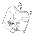
- Figure 5 is a perspective view of the bottom rear corner of the right enclosure piece showing an opening for receiving the spring clip and stand.
- Figure 6 is a perspective view of the inside surface of the bottom front corner of the left enclosure piece illustrating a spring clip and a stand snapped into a corresponding opening.
- Figure 7 is a perspective front and bottom view of the left part of the enclosure illustrating hinge details in the inside top surface.
- Figure 8 is a perspective rear and bottom view of the right part of the enclosure illustrating hinge details in the inside top surface.
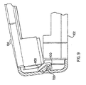
- Figure 9 is a cross section view illustrating how the 2 enclosure parts are hinged together.
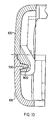
- Figure 10 is an expanded cross section view of the hinges as in figure 9 with the 2 enclosure parts fitted together.
- FIG. 1 illustrates an example embodiment of the invention.
- An enclosure has two major pieces, 100 and 102. Each enclosure piece has an opening 104 at two corners.
- Two metal spring clips 106 snap into the openings 104 to provide a high retention force for holding the pieces together.
- Two flexible stands 108 also snap into the openings 104, providing a cosmetic cover for the spring clips 106 as well as providing anti-slip feet to support the completed enclosure in a vertical orientation as illustrated in figure 1.
- one spring clip 106 is placed into each stand 108 and the two enclosure pieces (100 and 102) are simply pressed onto the spring clips and stands so that both spring clips and both stands snap into the openings 104 in the enclosure pieces.
- the spring clips 106 are fabricated from half-hard stainless steel.
- each stand 108 is injection molded using a thermoplastic elastomer (Sanoprene) from Advanced Elastomer Systems.
- Figure 1 illustrates the bottom, rear, and right side of the enclosure. Right and left are defined as viewed from the front side, which faces away in figure 1.
- the bottom is the side receiving the spring clips. Therefore, side 100 is the right side and side 102 is the left side.
- FIG 2 illustrates a view of one stand 108 along its longest dimension, with a spring clip 106 inserted into the stand.
- Figure 3 illustrates a top view of a stand 108, with a spring clip 106 inserted into the stand.
- Figure 4 illustrates a perspective view of a stand 108 without a spring clip.
- Each stand 108 has two retainer sections 200 and 202 on each end that provide retention of the stand to the enclosure.
- Figure 5 is an expanded external view of an opening 104 for receiving a stand and spring clip.
- a larger portion 502 of the opening 104 receives retainer section 202 (figures 2-4) of a stand.
- Figure 6 is an internal view of an opening with a stand and spring clip inserted.
- retainer section 200 inserts into slot 500 of the opening 104 and retainer section 202 and the spring clip 106 both insert into portion 502 of the opening 104.
- FIG. 7 is a view of the inside of the left side 102 of the enclosure, illustrating three wedge shaped hinge sections 700 along the inside surface of the top side.
- each hinge section 700 is about 6.4 mm long.
- the number and length of each hinge section may vary to accommodate various strengthening ribs, vent holes, or industrial design details.
- FIG 8 is a view of the inside of the right side 100 of the enclosure, illustrating three hinge sections 800 along the inside surface of the top side.
- Each hinge section 800 has a wedge shaped pocket (not visible in figure 8) for receiving a hinge section 700 (figure 7) from the left side of the enclosure.
- Figure 9 is front view of the right side 100 of the enclosure and the left side 102 of the enclosure with part of the top side cut away to illustrate a cross section through the hinges.
- Wedge shaped hinge section 700 on the left side 102 inserts into wedge shaped pocket 900 on the right side 100.
- the matching edges on the top side are brought together as illustrated in figure 9 to mate the hinge sections and then the matching edges of the bottom side are brought together.
- Figure 10 is an expanded view of the hinge parts further illustrating the wedge shaped hinge section 700 on the left side 102 and the wedge shaped pocket 900 on the right side 100.
- the combination of hinge and spring clips provides ease of automated assembly, ease of disassembly, low tooling cost, low part cost, pleasing aesthetics, and a capability to withstand rigorous vibration and mechanical shock.
- the example embodiment has been illustrated with two clips and two stands.
- a single clip and stand may be appropriate for some enclosure designs or more than two clips and stands may be appropriate.
- the example embodiment has been illustrated with a combination of hinge action and spring clips. In some enclosure designs, it may be appropriate to use only spring clips.
- the example embodiment has been illustrated with two stands for vertical operation. Additional feet may be added for optional horizontal or vertical operation.
Description
- This invention relates generally to enclosures used to house-electronic instruments and the like and more specifically to an enclosure with two pieces clamped together.
- Electronic instruments, computer peripheral devices, and similar products are often housed in an enclosure comprising two pieces, for example a top and a bottom, that are joined. Screws are commonly used to join the two enclosure pieces. For plastic molded enclosures, screws typically require metal inserts which in turn require an additional manufacturing step. In addition, in a high volume automated production environment, screws are relatively time consuming and require relatively expensive equipment.
- Plastic molded parts may also be designed to be snapped together. Features may be molded into one part that snap into corresponding features molded into another part. Snap fit parts are typically easy to assemble. However, the features may require substantially increased complexity in the plastic molds, requiring tighter tolerances and additional time to tune the molds to ensure that the parts are held precisely and securely. In addition, snap together parts may be difficult to disassemble for troubleshooting or changes after assembly, possibly requiring a tool or fixture to disengage multiple snap features. Finally, it is relatively difficult to design snap together parts with a high retention force. It is particularly difficult to design snap together parts that can survive the shake, vibration and drop requirements of many commercial consumer products.
- There are many ways of holding two parts together. Many of these ways function satisfactorily, but are not aesthetically acceptable for some consumer products. For example, various clamping devices are used for enclosures in harsh environments, such as automobile engine compartments, that function very well but may not be generally acceptable for use on a consumer product where appearance is important.
- An enclosure according to the preamble of claim 1 is shown in FR-A-2 564 684.
- There is an ongoing need for enclosures having ease of automated assembly, ease of disassembly, low tooling cost, low part cost, pleasing aesthetics, and a capability to withstand rigorous vibration and mechanical shock.
- The invention provides an enclosure as defined in claim 1.
- A two piece enclosure uses molded features for hinge action retention on one side and spring clips on an opposite side. The exclosure includes snap-on stands that serve as anti-slip feet to permit the enclosure to stand in a vertical orientation. The stands cover the spring clips. The spring clips provide a retention force that is substantially higher than the retention force provided by snap together parts. The parts are low cost and easy to remove. Most important, the combination of spring clips and snap-on stands facilitate automatic manufacturing, enabling the enclosure to simply be pressed against the clips and stands.
- Figure 1 is a perspective view of the bottom, right, and rear surfaces of an enclosure with a spring clip and stand in accordance with an example embodiment of the invention.
- Figure 2 is a plane front (or rear) view of a stand with a spring clip inserted.
- Figure 3 is a top view of a stand with a spring clip inserted.
- Figure 4 is a perspective view of a stand.
- Figure 5 is a perspective view of the bottom rear corner of the right enclosure piece showing an opening for receiving the spring clip and stand.
- Figure 6 is a perspective view of the inside surface of the bottom front corner of the left enclosure piece illustrating a spring clip and a stand snapped into a corresponding opening.
- Figure 7 is a perspective front and bottom view of the left part of the enclosure illustrating hinge details in the inside top surface.
- Figure 8 is a perspective rear and bottom view of the right part of the enclosure illustrating hinge details in the inside top surface.
- Figure 9 is a cross section view illustrating how the 2 enclosure parts are hinged together.
- Figure 10 is an expanded cross section view of the hinges as in figure 9 with the 2 enclosure parts fitted together.
- Figure 1 illustrates an example embodiment of the invention. An enclosure has two major pieces, 100 and 102. Each enclosure piece has an opening 104 at two corners. Two
metal spring clips 106 snap into theopenings 104 to provide a high retention force for holding the pieces together. Twoflexible stands 108 also snap into theopenings 104, providing a cosmetic cover for thespring clips 106 as well as providing anti-slip feet to support the completed enclosure in a vertical orientation as illustrated in figure 1. In an automated assembly line, onespring clip 106 is placed into eachstand 108 and the two enclosure pieces (100 and 102) are simply pressed onto the spring clips and stands so that both spring clips and both stands snap into theopenings 104 in the enclosure pieces. - In a specific example embodiment, the
spring clips 106 are fabricated from half-hard stainless steel. In the specific example embodiment, eachstand 108 is injection molded using a thermoplastic elastomer (Sanoprene) from Advanced Elastomer Systems. - Figure 1 illustrates the bottom, rear, and right side of the enclosure. Right and left are defined as viewed from the front side, which faces away in figure 1. The bottom is the side receiving the spring clips. Therefore,
side 100 is the right side andside 102 is the left side. - Figure 2 illustrates a view of one
stand 108 along its longest dimension, with aspring clip 106 inserted into the stand. Figure 3 illustrates a top view of astand 108, with aspring clip 106 inserted into the stand. Figure 4 illustrates a perspective view of astand 108 without a spring clip. Eachstand 108 has tworetainer sections - Figure 5 is an expanded external view of an opening 104 for receiving a stand and spring clip. A
slit 500 in a right or left side (right in figure 5), withgripping surfaces 504, receives the retainer section 200 (figures 2-4) of a stand. Alarger portion 502 of theopening 104 receives retainer section 202 (figures 2-4) of a stand. Figure 6 is an internal view of an opening with a stand and spring clip inserted. In particular, note thatretainer section 200 inserts intoslot 500 of theopening 104 andretainer section 202 and thespring clip 106 both insert intoportion 502 of theopening 104. - Figure 7 is a view of the inside of the
left side 102 of the enclosure, illustrating three wedge shapedhinge sections 700 along the inside surface of the top side. In the specific example embodiment, eachhinge section 700 is about 6.4 mm long. The number and length of each hinge section may vary to accommodate various strengthening ribs, vent holes, or industrial design details. - Figure 8 is a view of the inside of the
right side 100 of the enclosure, illustrating threehinge sections 800 along the inside surface of the top side. Eachhinge section 800 has a wedge shaped pocket (not visible in figure 8) for receiving a hinge section 700 (figure 7) from the left side of the enclosure. - Figure 9 is front view of the
right side 100 of the enclosure and theleft side 102 of the enclosure with part of the top side cut away to illustrate a cross section through the hinges. Wedge shapedhinge section 700 on theleft side 102 inserts into wedge shapedpocket 900 on theright side 100. During assembly, the matching edges on the top side are brought together as illustrated in figure 9 to mate the hinge sections and then the matching edges of the bottom side are brought together. - Figure 10 is an expanded view of the hinge parts further illustrating the wedge shaped
hinge section 700 on theleft side 102 and the wedge shapedpocket 900 on theright side 100. - While the enclosure pieces are pressed together, the enclosure pieces are pressed against spring clips and stands and discussed above to complete the assembly. The combination of hinge and spring clips provides ease of automated assembly, ease of disassembly, low tooling cost, low part cost, pleasing aesthetics, and a capability to withstand rigorous vibration and mechanical shock.
- The example embodiment has been illustrated with two clips and two stands. A single clip and stand may be appropriate for some enclosure designs or more than two clips and stands may be appropriate. The example embodiment has been illustrated with a combination of hinge action and spring clips. In some enclosure designs, it may be appropriate to use only spring clips. The example embodiment has been illustrated with two stands for vertical operation. Additional feet may be added for optional horizontal or vertical operation.
- The foregoing description of the present invention has been presented for purposes of illustration and description. It is not intended to be exhaustive or to limit the invention to the precise form disclosed, and other modifications and variations may be possible in light of the above teachings. The embodiment was chosen and described in order to best explain the principles of the invention and its practical application to thereby enable others skilled in the art to best utilize the invention in various embodiments and various modifications as are suited to the particular use contemplated. It is intended that the appended claims be construed to include other alternative embodiments of the invention except insofar as limited by the prior art.
Claims (2)
- An enclosure comprising:a first piece (100), the first piece having at least one opening (104);a second piece (102), the second piece having at least one opening;a spring clip (106) having first and second bent portions so that a spring force resists movement of the bent portions away from each other, the first bent portion being snapped into the opening of the first piece and the second bent portion being snapped into the opening of the second piece to join the two pieces; and characterised bya stand (108), the stand having first and second ends, the first end snapped into the opening of the first piece and the second end snapped into the opening of the second piece, the stand covering the spring clip.
- The enclosure of claim 1 further comprising:a first surface on the first piece, the opening for the first piece in the first surface;a second surface on the first piece that is parallel to the first surface;a pocket (800) on the second surface;a third surface on the second piece, the opening for the second piece in the third surface;a fourth surface on the second piece that is parallel to the third surface;a projection (700) on the fourth surface, positioned so that when the first piece is joined to the second piece the projection is inserted into the pocket, forming a hinge that holds the second and fourth surfaces together and permits the second surface to rotate relative to the fourth surface around the hinge.
Applications Claiming Priority (2)
| Application Number | Priority Date | Filing Date | Title |
|---|---|---|---|
| US935952 | 1997-09-23 | ||
| US08/935,952 US5921422A (en) | 1997-09-23 | 1997-09-23 | Enclosure with spring clamps and stands covering the clamps |
Publications (3)
| Publication Number | Publication Date |
|---|---|
| EP0903970A2 EP0903970A2 (en) | 1999-03-24 |
| EP0903970A3 EP0903970A3 (en) | 2000-02-23 |
| EP0903970B1 true EP0903970B1 (en) | 2003-10-29 |
Family
ID=25467958
Family Applications (1)
| Application Number | Title | Priority Date | Filing Date |
|---|---|---|---|
| EP98306851A Expired - Lifetime EP0903970B1 (en) | 1997-09-23 | 1998-08-26 | Enclosure with spring clamps and stands covering the clamps |
Country Status (4)
| Country | Link |
|---|---|
| US (1) | US5921422A (en) |
| EP (1) | EP0903970B1 (en) |
| JP (1) | JPH11163544A (en) |
| DE (1) | DE69819274T2 (en) |
Families Citing this family (13)
| Publication number | Priority date | Publication date | Assignee | Title |
|---|---|---|---|---|
| TW496971B (en) | 2001-02-09 | 2002-08-01 | Ind Tech Res Inst | Reflective type optical circulator |
| US20050201054A1 (en) * | 2004-03-12 | 2005-09-15 | John Norman | Coupler for mounting a device to another device, and related system and method |
| US20050230388A1 (en) * | 2004-04-16 | 2005-10-20 | Wen-Liang Wu | Computer host casing |
| US7168668B2 (en) * | 2004-08-04 | 2007-01-30 | Checkpoint Systems, Inc. | Damage resistant antenna mount |
| FR2888569B1 (en) * | 2005-07-13 | 2007-09-07 | Qualipac Soc Par Actions Simpl | FLUID CIRCULATION MEMBER AND VAPORIZATION DEVICE COMPRISING THE SAME |
| JP4681484B2 (en) * | 2006-03-30 | 2011-05-11 | ミライアル株式会社 | Thin plate storage container hook and thin plate storage container |
| CN200956692Y (en) * | 2006-09-22 | 2007-10-03 | 鸿富锦精密工业(深圳)有限公司 | Electronic device |
| JP5268142B2 (en) * | 2008-09-27 | 2013-08-21 | Hoya株式会社 | Mask blank storage case, mask blank storage method, and mask blank storage body |
| USD709507S1 (en) * | 2011-11-04 | 2014-07-22 | Seagate Technology Llc | Storage cartridge |
| DE102012103791B3 (en) * | 2012-04-30 | 2013-10-02 | Fujitsu Technology Solutions Intellectual Property Gmbh | Locking plate and an arrangement for locking a housing of an electronic device |
| WO2019245531A1 (en) | 2018-06-19 | 2019-12-26 | Hewlett-Packard Development Company, L.P. | Clamps having rotatable clamping elements |
| DE202018103694U1 (en) * | 2018-06-28 | 2019-10-09 | steute Schaltgeräte GmbH & Co. KG | Housing with a locking arrangement of a housing cover |
| JP2024514767A (en) * | 2021-03-24 | 2024-04-03 | モンディ・プロダクツ・リミテッド | Lockable indoor/outdoor grower |
Family Cites Families (9)
| Publication number | Priority date | Publication date | Assignee | Title |
|---|---|---|---|---|
| US3317073A (en) * | 1965-01-06 | 1967-05-02 | Schick Electric Inc | Plastic molded case halves with concealed interlock |
| US3868041A (en) * | 1973-03-16 | 1975-02-25 | Lippy Can Co | Can or container with resealable lid |
| US4330050A (en) * | 1980-05-23 | 1982-05-18 | Sangster Marshall A | Portable article carrying case |
| JPS5872708A (en) * | 1981-10-22 | 1983-04-30 | トヨタ自動車株式会社 | Two-split type resin cover |
| FR2564684B1 (en) * | 1984-05-15 | 1986-09-19 | Vedette Horlogerie | MODULAR HOUSING FOR ELECTRICAL AND / OR ELECTRONIC APPARATUS, PARTICULARLY FOR ELECTRONIC SWITCHING CLOCKS |
| US5032791A (en) * | 1989-08-04 | 1991-07-16 | A & E Manufacturing Co., Inc. | Apparatus for testing Hall effect device |
| US5013105A (en) * | 1990-01-19 | 1991-05-07 | E-Mu Systems, Inc. | Screwless electronic instrument enclosure |
| DE9420291U1 (en) * | 1994-12-19 | 1995-10-19 | Siemens Ag | Housing from at least two housing parts that can be assembled by means of a tongue and groove connection |
| AU4926796A (en) * | 1995-03-10 | 1996-10-02 | Ericsson Raynet | Environmental enclosure and method of sealing same |
-
1997
- 1997-09-23 US US08/935,952 patent/US5921422A/en not_active Expired - Fee Related
-
1998
- 1998-08-26 DE DE69819274T patent/DE69819274T2/en not_active Expired - Fee Related
- 1998-08-26 EP EP98306851A patent/EP0903970B1/en not_active Expired - Lifetime
- 1998-09-21 JP JP10266319A patent/JPH11163544A/en active Pending
Also Published As
| Publication number | Publication date |
|---|---|
| EP0903970A3 (en) | 2000-02-23 |
| JPH11163544A (en) | 1999-06-18 |
| DE69819274T2 (en) | 2004-07-15 |
| EP0903970A2 (en) | 1999-03-24 |
| DE69819274D1 (en) | 2003-12-04 |
| US5921422A (en) | 1999-07-13 |
Similar Documents
| Publication | Publication Date | Title |
|---|---|---|
| EP0903970B1 (en) | Enclosure with spring clamps and stands covering the clamps | |
| US5593219A (en) | Mainframe housing of a personal computer | |
| US5438778A (en) | Frame | |
| CA2106839C (en) | Apparatus for compliantly retaining a circuit board in a housing | |
| US5154505A (en) | Mounting structure for a lamp base for an automobile | |
| CN109755798A (en) | Modularization for connectors keeps frame | |
| US4274237A (en) | Holder for a decorative trim strip | |
| US5791606A (en) | Multi use radio installation kit | |
| US6233155B1 (en) | Encapsulation of printed circuit boards | |
| US5573317A (en) | Bracket apparatus for a cabinet | |
| JP2003188547A (en) | Mutually exchangeable customized bezels | |
| US11731449B2 (en) | System for coupling magnets to articles | |
| US5432298A (en) | Apparatus for covering electrical sockets or switches | |
| US6619595B2 (en) | Rear tray having speaker grill and method for installing speaker grill and rear tray to vehicle panel | |
| EP0047864B1 (en) | Holder for lengthy articles such as cables | |
| US8080732B2 (en) | Electronic device | |
| US4199204A (en) | Housing for a two-way radio or the like | |
| JPH04151010A (en) | Engagingly locking structure | |
| USD371016S (en) | Curio cabinet | |
| US20040210915A1 (en) | Screwless optical disc drive housing | |
| KR0126463Y1 (en) | Structure for assembling the leg of an electronic equipment | |
| EP0573422B1 (en) | Signboard and accessories for use in such a signboard | |
| KR20190000079U (en) | Cable storage box | |
| EP1296425B1 (en) | Expandable housing | |
| JP3675258B2 (en) | Housing mounting structure |
Legal Events
| Date | Code | Title | Description |
|---|---|---|---|
| PUAI | Public reference made under article 153(3) epc to a published international application that has entered the european phase |
Free format text: ORIGINAL CODE: 0009012 |
|
| AK | Designated contracting states |
Kind code of ref document: A2 Designated state(s): DE FR GB |
|
| AX | Request for extension of the european patent |
Free format text: AL;LT;LV;MK;RO;SI |
|
| PUAL | Search report despatched |
Free format text: ORIGINAL CODE: 0009013 |
|
| AK | Designated contracting states |
Kind code of ref document: A3 Designated state(s): AT BE CH CY DE DK ES FI FR GB GR IE IT LI LU MC NL PT SE |
|
| AX | Request for extension of the european patent |
Free format text: AL;LT;LV;MK;RO;SI |
|
| RIC1 | Information provided on ipc code assigned before grant |
Free format text: 7H 05K 5/00 A, 7F 16B 5/00 B |
|
| 17P | Request for examination filed |
Effective date: 20000516 |
|
| AKX | Designation fees paid |
Free format text: DE FR GB |
|
| RAP1 | Party data changed (applicant data changed or rights of an application transferred) |
Owner name: HEWLETT-PACKARD COMPANY, A DELAWARE CORPORATION |
|
| GRAH | Despatch of communication of intention to grant a patent |
Free format text: ORIGINAL CODE: EPIDOS IGRA |
|
| GRAS | Grant fee paid |
Free format text: ORIGINAL CODE: EPIDOSNIGR3 |
|
| GRAA | (expected) grant |
Free format text: ORIGINAL CODE: 0009210 |
|
| AK | Designated contracting states |
Kind code of ref document: B1 Designated state(s): DE FR GB |
|
| REG | Reference to a national code |
Ref country code: GB Ref legal event code: FG4D |
|
| REF | Corresponds to: |
Ref document number: 69819274 Country of ref document: DE Date of ref document: 20031204 Kind code of ref document: P |
|
| ET | Fr: translation filed | ||
| PLBE | No opposition filed within time limit |
Free format text: ORIGINAL CODE: 0009261 |
|
| STAA | Information on the status of an ep patent application or granted ep patent |
Free format text: STATUS: NO OPPOSITION FILED WITHIN TIME LIMIT |
|
| 26N | No opposition filed |
Effective date: 20040730 |
|
| PGFP | Annual fee paid to national office [announced via postgrant information from national office to epo] |
Ref country code: GB Payment date: 20060825 Year of fee payment: 9 |
|
| PGFP | Annual fee paid to national office [announced via postgrant information from national office to epo] |
Ref country code: FR Payment date: 20060831 Year of fee payment: 9 |
|
| PGFP | Annual fee paid to national office [announced via postgrant information from national office to epo] |
Ref country code: DE Payment date: 20061002 Year of fee payment: 9 |
|
| GBPC | Gb: european patent ceased through non-payment of renewal fee |
Effective date: 20070826 |
|
| REG | Reference to a national code |
Ref country code: FR Ref legal event code: ST Effective date: 20080430 |
|
| PG25 | Lapsed in a contracting state [announced via postgrant information from national office to epo] |
Ref country code: DE Free format text: LAPSE BECAUSE OF NON-PAYMENT OF DUE FEES Effective date: 20080301 |
|
| PG25 | Lapsed in a contracting state [announced via postgrant information from national office to epo] |
Ref country code: FR Free format text: LAPSE BECAUSE OF NON-PAYMENT OF DUE FEES Effective date: 20070831 |
|
| PG25 | Lapsed in a contracting state [announced via postgrant information from national office to epo] |
Ref country code: GB Free format text: LAPSE BECAUSE OF NON-PAYMENT OF DUE FEES Effective date: 20070826 |