EP0902690B1 - Balloon catheter - Google Patents
Balloon catheter Download PDFInfo
- Publication number
- EP0902690B1 EP0902690B1 EP97925035A EP97925035A EP0902690B1 EP 0902690 B1 EP0902690 B1 EP 0902690B1 EP 97925035 A EP97925035 A EP 97925035A EP 97925035 A EP97925035 A EP 97925035A EP 0902690 B1 EP0902690 B1 EP 0902690B1
- Authority
- EP
- European Patent Office
- Prior art keywords
- catheter
- balloon
- pump
- hose
- balloon catheter
- Prior art date
- Legal status (The legal status is an assumption and is not a legal conclusion. Google has not performed a legal analysis and makes no representation as to the accuracy of the status listed.)
- Expired - Lifetime
Links
Images

Classifications
-
- A—HUMAN NECESSITIES
- A61—MEDICAL OR VETERINARY SCIENCE; HYGIENE
- A61M—DEVICES FOR INTRODUCING MEDIA INTO, OR ONTO, THE BODY; DEVICES FOR TRANSDUCING BODY MEDIA OR FOR TAKING MEDIA FROM THE BODY; DEVICES FOR PRODUCING OR ENDING SLEEP OR STUPOR
- A61M60/00—Blood pumps; Devices for mechanical circulatory actuation; Balloon pumps for circulatory assistance
- A61M60/40—Details relating to driving
- A61M60/403—Details relating to driving for non-positive displacement blood pumps
- A61M60/408—Details relating to driving for non-positive displacement blood pumps the force acting on the blood contacting member being mechanical, e.g. transmitted by a shaft or cable
- A61M60/411—Details relating to driving for non-positive displacement blood pumps the force acting on the blood contacting member being mechanical, e.g. transmitted by a shaft or cable generated by an electromotor
- A61M60/414—Details relating to driving for non-positive displacement blood pumps the force acting on the blood contacting member being mechanical, e.g. transmitted by a shaft or cable generated by an electromotor transmitted by a rotating cable, e.g. for blood pumps mounted on a catheter
-
- A—HUMAN NECESSITIES
- A61—MEDICAL OR VETERINARY SCIENCE; HYGIENE
- A61M—DEVICES FOR INTRODUCING MEDIA INTO, OR ONTO, THE BODY; DEVICES FOR TRANSDUCING BODY MEDIA OR FOR TAKING MEDIA FROM THE BODY; DEVICES FOR PRODUCING OR ENDING SLEEP OR STUPOR
- A61M60/00—Blood pumps; Devices for mechanical circulatory actuation; Balloon pumps for circulatory assistance
- A61M60/10—Location thereof with respect to the patient's body
- A61M60/122—Implantable pumps or pumping devices, i.e. the blood being pumped inside the patient's body
- A61M60/126—Implantable pumps or pumping devices, i.e. the blood being pumped inside the patient's body implantable via, into, inside, in line, branching on, or around a blood vessel
- A61M60/13—Implantable pumps or pumping devices, i.e. the blood being pumped inside the patient's body implantable via, into, inside, in line, branching on, or around a blood vessel by means of a catheter allowing explantation, e.g. catheter pumps temporarily introduced via the vascular system
-
- A—HUMAN NECESSITIES
- A61—MEDICAL OR VETERINARY SCIENCE; HYGIENE
- A61M—DEVICES FOR INTRODUCING MEDIA INTO, OR ONTO, THE BODY; DEVICES FOR TRANSDUCING BODY MEDIA OR FOR TAKING MEDIA FROM THE BODY; DEVICES FOR PRODUCING OR ENDING SLEEP OR STUPOR
- A61M60/00—Blood pumps; Devices for mechanical circulatory actuation; Balloon pumps for circulatory assistance
- A61M60/20—Type thereof
- A61M60/205—Non-positive displacement blood pumps
- A61M60/216—Non-positive displacement blood pumps including a rotating member acting on the blood, e.g. impeller
- A61M60/226—Non-positive displacement blood pumps including a rotating member acting on the blood, e.g. impeller the blood flow through the rotating member having mainly radial components
-
- A—HUMAN NECESSITIES
- A61—MEDICAL OR VETERINARY SCIENCE; HYGIENE
- A61M—DEVICES FOR INTRODUCING MEDIA INTO, OR ONTO, THE BODY; DEVICES FOR TRANSDUCING BODY MEDIA OR FOR TAKING MEDIA FROM THE BODY; DEVICES FOR PRODUCING OR ENDING SLEEP OR STUPOR
- A61M60/00—Blood pumps; Devices for mechanical circulatory actuation; Balloon pumps for circulatory assistance
- A61M60/30—Medical purposes thereof other than the enhancement of the cardiac output
- A61M60/31—Medical purposes thereof other than the enhancement of the cardiac output for enhancement of in vivo organ perfusion, e.g. retroperfusion
- A61M60/32—Medical purposes thereof other than the enhancement of the cardiac output for enhancement of in vivo organ perfusion, e.g. retroperfusion of heart muscle tissues, e.g. using coronary sinus occlusion
-
- A—HUMAN NECESSITIES
- A61—MEDICAL OR VETERINARY SCIENCE; HYGIENE
- A61M—DEVICES FOR INTRODUCING MEDIA INTO, OR ONTO, THE BODY; DEVICES FOR TRANSDUCING BODY MEDIA OR FOR TAKING MEDIA FROM THE BODY; DEVICES FOR PRODUCING OR ENDING SLEEP OR STUPOR
- A61M60/00—Blood pumps; Devices for mechanical circulatory actuation; Balloon pumps for circulatory assistance
- A61M60/40—Details relating to driving
- A61M60/403—Details relating to driving for non-positive displacement blood pumps
- A61M60/408—Details relating to driving for non-positive displacement blood pumps the force acting on the blood contacting member being mechanical, e.g. transmitted by a shaft or cable
- A61M60/411—Details relating to driving for non-positive displacement blood pumps the force acting on the blood contacting member being mechanical, e.g. transmitted by a shaft or cable generated by an electromotor
-
- A—HUMAN NECESSITIES
- A61—MEDICAL OR VETERINARY SCIENCE; HYGIENE
- A61M—DEVICES FOR INTRODUCING MEDIA INTO, OR ONTO, THE BODY; DEVICES FOR TRANSDUCING BODY MEDIA OR FOR TAKING MEDIA FROM THE BODY; DEVICES FOR PRODUCING OR ENDING SLEEP OR STUPOR
- A61M60/00—Blood pumps; Devices for mechanical circulatory actuation; Balloon pumps for circulatory assistance
- A61M60/50—Details relating to control
- A61M60/508—Electronic control means, e.g. for feedback regulation
- A61M60/577—High-frequency driving
-
- A—HUMAN NECESSITIES
- A61—MEDICAL OR VETERINARY SCIENCE; HYGIENE
- A61M—DEVICES FOR INTRODUCING MEDIA INTO, OR ONTO, THE BODY; DEVICES FOR TRANSDUCING BODY MEDIA OR FOR TAKING MEDIA FROM THE BODY; DEVICES FOR PRODUCING OR ENDING SLEEP OR STUPOR
- A61M60/00—Blood pumps; Devices for mechanical circulatory actuation; Balloon pumps for circulatory assistance
- A61M60/80—Constructional details other than related to driving
- A61M60/841—Constructional details other than related to driving of balloon pumps for circulatory assistance
- A61M60/843—Balloon aspects, e.g. shapes or materials
-
- A—HUMAN NECESSITIES
- A61—MEDICAL OR VETERINARY SCIENCE; HYGIENE
- A61M—DEVICES FOR INTRODUCING MEDIA INTO, OR ONTO, THE BODY; DEVICES FOR TRANSDUCING BODY MEDIA OR FOR TAKING MEDIA FROM THE BODY; DEVICES FOR PRODUCING OR ENDING SLEEP OR STUPOR
- A61M25/00—Catheters; Hollow probes
- A61M25/10—Balloon catheters
- A61M2025/1043—Balloon catheters with special features or adapted for special applications
- A61M2025/1095—Balloon catheters with special features or adapted for special applications with perfusion means for enabling blood circulation while the balloon is in an inflated state or in a deflated state, e.g. permanent by-pass within catheter shaft
-
- A—HUMAN NECESSITIES
- A61—MEDICAL OR VETERINARY SCIENCE; HYGIENE
- A61M—DEVICES FOR INTRODUCING MEDIA INTO, OR ONTO, THE BODY; DEVICES FOR TRANSDUCING BODY MEDIA OR FOR TAKING MEDIA FROM THE BODY; DEVICES FOR PRODUCING OR ENDING SLEEP OR STUPOR
- A61M25/00—Catheters; Hollow probes
-
- A—HUMAN NECESSITIES
- A61—MEDICAL OR VETERINARY SCIENCE; HYGIENE
- A61M—DEVICES FOR INTRODUCING MEDIA INTO, OR ONTO, THE BODY; DEVICES FOR TRANSDUCING BODY MEDIA OR FOR TAKING MEDIA FROM THE BODY; DEVICES FOR PRODUCING OR ENDING SLEEP OR STUPOR
- A61M60/00—Blood pumps; Devices for mechanical circulatory actuation; Balloon pumps for circulatory assistance
- A61M60/10—Location thereof with respect to the patient's body
- A61M60/122—Implantable pumps or pumping devices, i.e. the blood being pumped inside the patient's body
- A61M60/126—Implantable pumps or pumping devices, i.e. the blood being pumped inside the patient's body implantable via, into, inside, in line, branching on, or around a blood vessel
- A61M60/148—Implantable pumps or pumping devices, i.e. the blood being pumped inside the patient's body implantable via, into, inside, in line, branching on, or around a blood vessel in line with a blood vessel using resection or like techniques, e.g. permanent endovascular heart assist devices
-
- A—HUMAN NECESSITIES
- A61—MEDICAL OR VETERINARY SCIENCE; HYGIENE
- A61M—DEVICES FOR INTRODUCING MEDIA INTO, OR ONTO, THE BODY; DEVICES FOR TRANSDUCING BODY MEDIA OR FOR TAKING MEDIA FROM THE BODY; DEVICES FOR PRODUCING OR ENDING SLEEP OR STUPOR
- A61M60/00—Blood pumps; Devices for mechanical circulatory actuation; Balloon pumps for circulatory assistance
- A61M60/80—Constructional details other than related to driving
- A61M60/802—Constructional details other than related to driving of non-positive displacement blood pumps
- A61M60/833—Occluders for preventing backflow
-
- A—HUMAN NECESSITIES
- A61—MEDICAL OR VETERINARY SCIENCE; HYGIENE
- A61M—DEVICES FOR INTRODUCING MEDIA INTO, OR ONTO, THE BODY; DEVICES FOR TRANSDUCING BODY MEDIA OR FOR TAKING MEDIA FROM THE BODY; DEVICES FOR PRODUCING OR ENDING SLEEP OR STUPOR
- A61M60/00—Blood pumps; Devices for mechanical circulatory actuation; Balloon pumps for circulatory assistance
- A61M60/80—Constructional details other than related to driving
- A61M60/855—Constructional details other than related to driving of implantable pumps or pumping devices
- A61M60/865—Devices for guiding or inserting pumps or pumping devices into the patient's body
Definitions
- the invention relates to a balloon catheter, which in a Blood vessel can be inserted, for example Vasoconstrictions widen or part of the wall of the blood vessel temporarily from contact with the blood stream cordon off.
- Balloon catheters with a catheter tube are known, the tubular balloon carrier at the distal end has, on which an annular balloon sits.
- the balloon stands above one through the catheter tube lumen passing through with an extracorporeal pressure source in connection.
- an extracorporeal pressure source in connection.
- ischemia deficiency supply
- Perfusion catheter perfusion catheter
- autoperfusion catheters DE 92 07 395 U1
- active Perfusion systems with the help of an external High pressure pump connected to the distal end of the catheter is going through continuous perfusion the catheter lumen occurs.
- certain pressure actively built up that is independent of the patient's current blood pressure. To do this however, arterialized blood is drawn from the patient the extracorporeally into the lumen of the catheter tube is pumped.
- pump pressures up to approx. 12 bar
- an intravascular blood pump is shown Cardiac support known.
- This blood pump can go through a blood vessel is inserted into the heart. It has an elongated tube in which a helical Is arranged by a propeller flexible shaft is driven. This pump sucks axially and points at the opposite exit end Holes for radial outflow.
- the blood pump is placed in the opening of the heart valve, the suction end being in one of the cardiac ventricles located while the outflow end is arranged in the aorta is.
- US-A-5 163 910 describes a balloon catheter containing a pump assembly.
- the preamble of claim 1 corresponds to the publication of this document.
- the invention has for its object a balloon catheter to create a simplified active Perfusion system forms.
- the balloon catheter there is a pump arranged in the course of the catheter, proximal from the balloon carrier.
- the pump sucks laterally through appropriate Openings blood from the blood vessel on and pumps it axially through the balloon carrier. Since the Pump is placed directly in front of the balloon carrier, only a relatively low pump pressure is required.
- the pump is so small that it is directly in the area of the Surgery, i.e. near the balloon, in the catheter can be placed so that the length of the to be flushed Lumens is short, making the pressure drop relative is kept low.
- the pump has such a small one Diameter that they are in the course of the catheter Blood vessel can be inserted without blocking it. Are from treatment with balloon catheters usually affected smaller blood vessels.
- the maximum Outside diameter of the pump should not be about 1.4 mm exceed.
- Such a small pump can be used in the Catheters are integrated so that they are immediately in front the balloon carrier that passes through the treatment site of the Blood vessel passes through. The pump sucks in the direction of flow of the vessel from the area higher Pressure blood through at least one side inlet and promotes this in the low pressure area beyond of the inflated balloons.
- the pump speed is preferably in the range of 80,000 to 150,000 rpm.
- the balloon catheter is preferably used for stretching Vascular narrowing, especially in the coronary artery area, in the carotid arteries and the like. But it is also possible to use the balloon catheter to Wire basket (stent) for widening vasoconstrictions to place.
- Wire basket stent
- the perfusion catheter The invention can be arranged in series Have balloons.
- the balloons seal a section of length of the vessel temporarily to in this area to be able to sew a bypass.
- the blood is flowing continue through the tubular balloon carrier while the sealed vessel section for surgical interventions is available.
- the invention creates an active perfusion catheter with integrated pump. This corresponds in its Largely handling passive autoperfusion catheters, is in its performance but the active perfusion systems comparable. Another advantage is there in that the balloon carrier with a very low Outside diameter of about 1 mm can be realized can. This is in almost all cases, even at severe stenosis, ensuring placement of the balloon area in the stenosis.
- the pump is preferably of a flexible shaft powered with one at the proximal end of the catheter tube provided motor is connected.
- Such Pumps that only consist of a pump housing and the can consist of a rotating impeller with a very small outside diameter of about 1.5 mm are manufactured.
- a guidewire is usually inserted, over which the catheter is then pushed.
- a such laying with a guide wire is also provided in the balloon catheter according to the invention.
- the guide wire must pass through the pump be passed through.
- the impeller of the pump or the pump itself is therefore designed so that it Passage of a guidewire that has a diameter of about 0.3 mm. To consider is that the pump is only started after the guidewire is sufficiently far from the immediate Pump area was pulled out. During the Laying the catheter is acceptable if the Guide wire blocked the impeller.
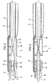
- the balloon catheter 1 according to FIG. 1 has an elongated one Catheter tube 10, the length of which is approximately 1 m and its diameter is approximately 1.3 mm.
- the flexible catheter tube 10 has a central one Tube lumen 11 with a diameter of approximately 0.8 mm on. It also runs through the wall of the catheter tube 10 another lumen 12 for the supply of Pressurized fluid to the balloon 14.
- the tubular one is at the tip of the catheter Balloon carrier 13 with an inner diameter of approximately 0.8 mm and an outer diameter of approx. 1.0 mm.
- This Balloon carrier 13 is surrounded by at least one balloon 14.
- the balloon 14 is connected via a line 15 to the Lumen 12 of the catheter tube 10 in connection.
- the the front end of the balloon carrier 12 is tapered and has one axial and several lateral Blood outlet openings.
- the pump 16 Between the catheter tube 10 and the balloon carrier 13 is the pump 16. This has a tubular Pump housing 17 with an outer diameter of approx. 1.5 mm.
- the proximal end 17a of the pump housing is attached to the end of the catheter tube 10 and the distal end 17b is with the balloon carrier 13 connected.
- the pump housing 17 is made of metal and it contains a bearing 18 in which the shaft 19 of the impeller 20 is stored.
- the end of the catheter tube 10 is between the bearing 18 and the pump housing 17 fitted.
- Immediately following that End of the catheter tube 10 are on the housing 17th side inlets 21 provided through the blood radially can enter the pump housing 17. In that area, in which the impeller 20 is located is the housing 17 circumferentially closed.
- the impeller 20 has several wings 22 that are helical about the axis are arranged around and over an angular range extend of at least 150 °.
- the axial length of the Pump wheel 20 is approximately twice the maximum Diameter of this impeller.
- the impeller 20 ends immediately in front of the balloon carrier 13.
- the shaft 19 of the impeller 20 is flexible Connected shaft 23 which inside the lumen 11 of the Catheter tube 10 runs and at the proximal end is connected to an external electric motor that the Shaft with a speed of the order of magnitude 100,000 rpm. drives.
- the pump 16 conveys blood from the inlets 21 through the balloon carrier 13.
- the distal end of the balloon carrier 13 is open or provided with openings, so that the blood there from the balloon carrier 13 into the blood vessel can exit.
- Fig. 2 the balloon catheter according to the invention with an additional Guide wire 25 described, the first in is placed in the blood vessel and then the catheter is pushed.
- This flexible guide wire 25 generally runs outside the catheter tube 10.
- the diameter of the Guide wire is approximately 0.3 mm, making the guide wire through the impeller 20 between its wings can run through.
- the guidewire 25 is in the pump housing, there is no rotation of the pump wheel. After placing the catheter the guidewire is at least on for treatment pulled out of the pump housing.
- the channel is 26 placed and designed the impeller 20 so that the Guide wire 25 at any time after treatment again via the standing impeller 20 in the direction of Balloons pushed through the balloon carrier 13 can be used to guide the system again using the guide wire 25 to place in a changed position without withdrawing the balloon catheter 1 completely to have to.
- each of the balloons 15 can be provided across the pump 16. Yet should the catheter be in its thickest area, i.e. in the Pump 16 area, especially for use in the coronary area (Carotenes), not significantly over 1.5 mm Diameter, otherwise the placement of the Catheters over a standard insertion catheter with an inner diameter of 2 mm would no longer be possible. Further it is necessary that the length of the pump housing 17 does not exceed approx. 6 mm.
- the exemplary embodiments described above relate on a balloon catheter, the one based on the low pressure principle working pump 16, which in the vicinity of the balloon carrier, i.e. at the end of the catheter tube, is arranged.
- the pump needs to generate only a relatively low pressure.
Landscapes
- Health & Medical Sciences (AREA)
- Engineering & Computer Science (AREA)
- Heart & Thoracic Surgery (AREA)
- Cardiology (AREA)
- Biomedical Technology (AREA)
- Veterinary Medicine (AREA)
- Animal Behavior & Ethology (AREA)
- Anesthesiology (AREA)
- Public Health (AREA)
- Hematology (AREA)
- Life Sciences & Earth Sciences (AREA)
- Mechanical Engineering (AREA)
- General Health & Medical Sciences (AREA)
- Physics & Mathematics (AREA)
- Optics & Photonics (AREA)
- Geometry (AREA)
- Vascular Medicine (AREA)
- Media Introduction/Drainage Providing Device (AREA)
- External Artificial Organs (AREA)
Description
Die Erfindung betrifft einen Ballonkatheter, der in ein Blutgefäß eingeführt werden kann, um beispielsweise Gefäßverengungen aufzuweiten oder einen Teil der Wand des Blutgefäßes vorübergehend vom Kontakt mit dem Blutstrom abzusperren.The invention relates to a balloon catheter, which in a Blood vessel can be inserted, for example Vasoconstrictions widen or part of the wall of the blood vessel temporarily from contact with the blood stream cordon off.
Bekannt sind Ballonkatheter mit einem Katheterschlauch, der am distalen Ende einen rohrförmigen Ballonträger aufweist, auf welchem ein ringförmiger Ballon sitzt. Der Ballon steht über ein durch den Katheterschlauch hindurchgehendes Lumen mit einer extrakorporalen Druckquelle in Verbindung. Durch Einleiten einer Flüssigkeit unter Druck wird der Ballon aufgeweitet. Dabei erfolgt normalerweise ein Totalverschluß des Blutgefäßes, mit der Folge einer Mangelversorgung (Ischämie) der nachfolgenden Organregionen. Um diese zu vermeiden, werden Perfusionskatheter (Durchblutungskatheter) benutzt. Zu diesen gehören Autoperfusionskatheter (DE 92 07 395 U1), die einen durch den Ballonträger hindurchgehenden Durchlaß aufweisen, so daß eine Blutströmung durch das Innere des ringförmigen Ballons erfolgt, sowie aktive Perfusionssysteme, bei denen mit Hilfe einer externen Hochdruckpumpe, die an das distale Katheterende angeschlossen wird, eine kontinuierliche Perfusion durch das Katheterlumen erfolgt. Im Gegensatz zu Autoperfusionskathetern wird bei aktiven Perfusionssystemen ein bestimmter Druck aktiv aufgebaut, der unabhängig von dem aktuellen Blutdruck des Patienten ist. Hierzu muß dem Patienten jedoch arterialisiertes Blut entnommen werden, das extrakorporal in das Lumen des Katheterschlauchs gepumpt wird. Zudem sind sehr hohe Pumpendrücke (bis ca. 12 bar) aufgrund der großen Druckverluste im kleinlumigen Katheterschlauch erforderlich, um ca. 40 bis 60 ml/min. zu fördern.Balloon catheters with a catheter tube are known, the tubular balloon carrier at the distal end has, on which an annular balloon sits. The balloon stands above one through the catheter tube lumen passing through with an extracorporeal pressure source in connection. By introducing a liquid the balloon is expanded under pressure. This is done usually a total occlusion of the blood vessel, with the consequence of a deficiency supply (ischemia) of the following Organ regions. To avoid this, be Perfusion catheter (perfusion catheter) used. To these include autoperfusion catheters (DE 92 07 395 U1), the one passing through the balloon carrier Have passage so that blood flow through the Inside of the ring-shaped balloon is done as well as active Perfusion systems with the help of an external High pressure pump connected to the distal end of the catheter is going through continuous perfusion the catheter lumen occurs. In contrast to autoperfusion catheters is used in active perfusion systems certain pressure actively built up that is independent of the patient's current blood pressure. To do this however, arterialized blood is drawn from the patient the extracorporeally into the lumen of the catheter tube is pumped. There are also very high pump pressures (up to approx. 12 bar) due to the large pressure drops in the small-lumen catheter tube required to approx. 40 to 60 ml / min. to promote.
Aus US-A-4 969 865 ist eine intravasale Blutpumpe bei Herzunterstützung bekannt. Diese Blutpumpe kann durch ein Blutgefäß hindurch in das Herz eingeführt werden. Sie weist ein längliches Rohr auf, in dem ein schraubenförmiger Propeller angeordnet ist, der durch eine flexible Welle angetrieben wird. Diese Pumpe saugt axial an und sie weist am entgegengesetzten Austrittsende Löcher für das radiale Abströmen auf. Im Betrieb wird die Blutpumpe in der Öffnung der Herzklappe plaziert, wobei das Ansaugende sich in einem der Herzventrikel befindet, während das Abströmende in der Aorta angeordnet ist.From US-A-4 969 865 an intravascular blood pump is shown Cardiac support known. This blood pump can go through a blood vessel is inserted into the heart. It has an elongated tube in which a helical Is arranged by a propeller flexible shaft is driven. This pump sucks axially and points at the opposite exit end Holes for radial outflow. In operation the blood pump is placed in the opening of the heart valve, the suction end being in one of the cardiac ventricles located while the outflow end is arranged in the aorta is.
US-A-5 163 910 beschreibt ein, eine Pumpanordnung enthaltener, Ballonkatheter. Der Oberbegriff des Anspruchs 1 entspricht der Veröffentlichung dieses Dokumentes.US-A-5 163 910 describes a balloon catheter containing a pump assembly. The preamble of
Der Erfindung liegt die Aufgabe zugrunde, einen Ballonkatheter zu schaffen, der ein vereinfachtes aktives Perfusionssystem bildet. The invention has for its object a balloon catheter to create a simplified active Perfusion system forms.
Die Lösung dieser Aufgabe erfolgt erfindungsgemäß mit
den im Patentanspruch 1 angegebenen Merkmalen.This object is achieved with the invention
the features specified in
Bei dem erfindungsgemäßen Ballonkatheter ist eine Pumpe im Zuge des Katheters angeordnet, und zwar proximal von dem Ballonträger. Die Pumpe saugt seitlich über entsprechende Öffnungen Blut aus dem Blutgefäß an und pumpt es axial durch den Ballonträger hindurch. Da die Pumpe unmittelbar vor dem Ballonträger angeordnet ist, ist nur ein relativ geringer Pumpendruck erforderlich. Die Pumpe ist so klein, daß sie direkt im Bereich des Eingriffs, also in der Nähe des Ballons, im Katheter plaziert werden kann, so daß die Länge des zu durchspülenden Lumens kurz ist, wodurch der Druckverlust relativ gering gehalten wird. Die Pumpe hat einen so kleinen Durchmesser, daß sie im Zuge des Katheters in das Blutgefäß eingeführt werden kann, ohne dieses zu versperren. Von einer Behandlung mit Ballonkathetern sind in der Regel kleinere Blutgefäße betroffen. Der maximale Außendurchmesser der Pumpe sollte etwa 1,4 mm nicht übersteigen. Eine derartig kleine Pumpe kann in den Katheter integriert werden, so daß sie unmittelbar vor dem Ballonträger, der durch die Behandlungsstelle des Blutgefäßes hindurchgeht, liegt. Dabei saugt die Pumpe in Strömungsrichtung des Gefäßes aus dem Bereich höheren Drucks Blut über mindestens einen seitlichen Einlaß an und fördert dieses in den Niederdruckbereich jenseits der aufgeblasenen Ballons.In the balloon catheter according to the invention there is a pump arranged in the course of the catheter, proximal from the balloon carrier. The pump sucks laterally through appropriate Openings blood from the blood vessel on and pumps it axially through the balloon carrier. Since the Pump is placed directly in front of the balloon carrier, only a relatively low pump pressure is required. The pump is so small that it is directly in the area of the Surgery, i.e. near the balloon, in the catheter can be placed so that the length of the to be flushed Lumens is short, making the pressure drop relative is kept low. The pump has such a small one Diameter that they are in the course of the catheter Blood vessel can be inserted without blocking it. Are from treatment with balloon catheters usually affected smaller blood vessels. The maximum Outside diameter of the pump should not be about 1.4 mm exceed. Such a small pump can be used in the Catheters are integrated so that they are immediately in front the balloon carrier that passes through the treatment site of the Blood vessel passes through. The pump sucks in the direction of flow of the vessel from the area higher Pressure blood through at least one side inlet and promotes this in the low pressure area beyond of the inflated balloons.
Wegen der erforderlichen Kleinheit der Pumpe muß diese mit relativ hohen Drehzahlen betrieben werden, um die erforderliche Förderleistung von beispielsweise 60 cm3/min. zu erreichen. Die Pumpendrehzahl liegt vorzugsweise im Bereich von 80.000 bis 150.000 U/min.Because of the required smallness of the pump, it must be operated at relatively high speeds in order to achieve the required delivery rate of, for example, 60 cm 3 / min. to reach. The pump speed is preferably in the range of 80,000 to 150,000 rpm.
Der Ballonkatheter wird vorzugsweise für das Dehnen von Gefäßverengungen, speziell im Herzkranzgefäßbereich, in den Halsschlagadern u.dgl., eingesetzt. Es ist aber auch möglich, den Ballonkatheter dazu zu benutzen, einen Drahtkorb (Stent) zur Weitstellung von Gefäßverengungen zu plazieren.The balloon catheter is preferably used for stretching Vascular narrowing, especially in the coronary artery area, in the carotid arteries and the like. But it is also possible to use the balloon catheter to Wire basket (stent) for widening vasoconstrictions to place.
Das Perfusionskatheter der Erfindung kann mehrere hintereinander angeordnete Ballons aufweisen. Die Ballons dichten einen Längenabschnitt des Gefäßes vorübergehend ab, um in diesem Bereich einen Bypaß annähen zu können. Das Blut strömt weiterhin durch den rohrförmigen Ballonträger, während der abgedichtete Gefäßabschnitt für operative Eingriffe zur Verfügung steht.The perfusion catheter The invention can be arranged in series Have balloons. The balloons seal a section of length of the vessel temporarily to in this area to be able to sew a bypass. The blood is flowing continue through the tubular balloon carrier while the sealed vessel section for surgical interventions is available.
Die Erfindung schafft einen aktiven Perfusionskatheter mit integrierter Pumpe. Dieser entspricht in seiner Handhabung weitgehend den passiven Autoperfusionskathetern, ist in seiner Leistung aber den aktiven Perfusionssystemen vergleichbar. Ein weiterer Vorteil besteht darin, daß der Ballonträger mit einem sehr geringen Außendurchmesser von etwa 1 mm realisiert werden kann. Hierdurch ist in fast allen Fällen, selbst bei starken Stenosen, gewährleistet, daß eine Plazierung des Ballonbereichs in der Stenose erfolgen kann.The invention creates an active perfusion catheter with integrated pump. This corresponds in its Largely handling passive autoperfusion catheters, is in its performance but the active perfusion systems comparable. Another advantage is there in that the balloon carrier with a very low Outside diameter of about 1 mm can be realized can. This is in almost all cases, even at severe stenosis, ensuring placement of the balloon area in the stenosis.
Vorzugsweise ist die Pumpe von einer flexiblen Welle angetrieben, die mit einem am proximalen Ende des Katheterschlauchs vorgesehenen Motor verbunden ist. Solche Pumpen, die nur aus einem Pumpengehäuse und dem darin rotierend angeordneten Flügelrad bestehen, können mit einem sehr geringen Außendurchmesser von etwa 1,5 mm gefertigt werden. Generell ist es im Rahmen der Erfindung aber auch möglich, einen Pumpenmotor in den Katheter, in direkter Nähe zur Pumpe, zu integrieren, wobei der Motor dann das Pumpenrad unmittelbar antreibt.The pump is preferably of a flexible shaft powered with one at the proximal end of the catheter tube provided motor is connected. Such Pumps that only consist of a pump housing and the can consist of a rotating impeller with a very small outside diameter of about 1.5 mm are manufactured. Generally, it is within the scope of the invention but also possible to put a pump motor in the Integrate catheters in close proximity to the pump the motor then drives the impeller directly.
Um einen Ballonkatheter in einem Blutgefäß zu plazieren, wird in der Regel ein Führungsdraht eingebracht, über den der Katheter anschließend geschoben wird. Eine derartige Verlegung mit einem Führungsdraht ist auch bei dem erfindungsgemäßen Ballonkatheter vorgesehen. Hierbei muß der Führungsdraht allerdings durch die Pumpe hindurchgeführt werden. Das Flügelrad der Pumpe oder die Pumpe selbst ist demnach so ausgebildet, daß es den Durchgang eines Führungsdrahtes, der einen Durchmesser von etwa 0,3 mm hat, ermöglicht. Zu berücksichtigen ist, daß die Pumpe erst in Betrieb genommen wird, nachdem der Führungsdraht hinreichend weit aus dem unmittelbaren Pumpenbereich herausgezogen wurde. Während der Verlegung des Katheters ist es hinnehmbar, wenn der Führungsdraht das Pumpenrad blockiert.To place a balloon catheter in a blood vessel, a guidewire is usually inserted, over which the catheter is then pushed. A such laying with a guide wire is also provided in the balloon catheter according to the invention. Here the guide wire must pass through the pump be passed through. The impeller of the pump or the pump itself is therefore designed so that it Passage of a guidewire that has a diameter of about 0.3 mm. To consider is that the pump is only started after the guidewire is sufficiently far from the immediate Pump area was pulled out. During the Laying the catheter is acceptable if the Guide wire blocked the impeller.
Im folgenden werden unter Bezugnahme auf die Zeichnungen Ausführungsbeispiele der Erfindung näher erläutert.The following are with reference to the drawings Embodiments of the invention explained in more detail.
Es zeigen:
- Fig. 1
- einen Längsschnitt durch den distalen Endbereich des Ballonkatheters,
- Fig. 2
- den Ballonkatheter nach Fig. 1 mit eingeschobenem Führungsdraht, wobei die Pumpe eine Monorail-Führung bildet, und
- Fig. 3
- ein Ausführungsbeispiel, bei dem der Führungsdraht koaxial durch die Pumpe hindurchgeht.
- Fig. 1
- a longitudinal section through the distal end region of the balloon catheter,
- Fig. 2
- 1 with inserted guide wire, the pump forming a monorail guide, and
- Fig. 3
- an embodiment in which the guide wire passes coaxially through the pump.
Der Ballonkatheter 1 nach Fig. 1 weist einen langgestreckten
Katheterschlauch 10 auf, dessen Länge etwa 1
m beträgt und dessen Durchmesser ca. 1,3 mm beträgt.
Der flexible Katheterschlauch 10 weist ein zentrisches
Schlauchlumen 11 mit einem Durchmesser von ca. 0,8 mm
auf. Ferner verläuft durch die Wand des Katheterschlauchs
10 ein weiteres Lumen 12 zur Zuleitung von
Druckfluid zu dem Ballon 14.The
An der Katheterspitze befindet sich der rohrförmige
Ballonträger 13 mit einem Innendurchmesser von ca. 0,8
mm und einem Außendurchmesser von ca. 1,0 mm. Dieser
Ballonträger 13 ist von mindestens einem Ballon 14 umgeben.
Der Ballon 14 steht über eine Leitung 15 mit dem
Lumen 12 des Katheterschlauchs 10 in Verbindung. Das
vordere Ende des Ballonträgers 12 ist verjüngt ausgebildet
und weist eine axiale und mehrere seitliche
Blutaustrittsöffnungen auf.The tubular one is at the tip of the
Zwischen dem Katheterschlauch 10 und dem Ballonträger
13 befindet sich die Pumpe 16. Diese weist ein rohrförmiges
Pumpengehäuse 17 mit einem Außendurchmesser von
ca. 1,5 mm auf. Das proximale Ende 17a des Pumpengehäuses
ist an dem Ende des Katheterschlauchs 10 befestigt
und das distale Ende 17b ist mit dem Ballonträger 13
verbunden. Das Pumpengehäuse 17 besteht aus Metall und
es enthält ein Lager 18, in dem die Welle 19 des Pumpenrades
20 gelagert ist. Das Ende des Katheterschlauchs
10 ist zwischen dem Lager 18 und dem Pumpengehäuse
17 eingepaßt. Unmittelbar im Anschluß an das
Ende des Katheterschlauchs 10 sind an dem Gehäuse 17
seitliche Einlässe 21 vorgesehen, durch die Blut radial
in das Pumpengehäuse 17 eintreten kann. In dem Bereich,
im dem sich das Pumpenrad 20 befindet, ist das Gehäuse
17 umfangsmäßig geschlossen. Das Pumpenrad 20 weist
mehrere Flügel 22 auf, die schraubenförmig um die Achse
herum angeordnet sind und sich über einen Winkelbereich
von mindestens 150° erstrecken. Die axiale Länge des
Pumpenrades 20 beträgt ca. das Doppelte des maximalen
Durchmessers dieses Pumpenrades. Das Pumpenrad 20 endet
unmittelbar vor dem Ballonträger 13.Between the
Die Welle 19 des Pumpenrades 20 ist mit einer flexiblen
Welle 23 verbunden, die im Innern des Lumens 11 des
Katheterschlauchs 10 verläuft und am proximalen Ende
mit einem externen Elektromotor verbunden ist, der die
Welle mit einer Drehzahl in der Größenordnung von
100.000 U/min. antreibt.The
Während der Ballonbereich des Katheters beispielsweise
in den Bereich einer Stenose eingeführt und der Ballon
14 unter Druck gesetzt und dadurch aufgeweitet wurde,
fördert die Pumpe 16 Blut von den Einlässen 21 durch
den Ballonträger 13 hindurch. Das distale Ende des Ballonträgers
13 ist offen oder mit Öffnungen versehen, so
daß das Blut dort aus dem Ballonträger 13 in das Blutgefäß
hinein austreten kann. During the balloon area of the catheter, for example
inserted into the area of a stenosis and the
In Fig. 2 wird das Ballonkatheter
gemäß der Erfindung mit einem zusätzlichen
Führungsdraht 25 geschildert, der zunächst in
dem Blutgefäß plaziert wird und über den dann der Katheter
geschoben wird. Dieser flexible Führungsdraht 25
verläuft generell außerhalb des Katheterschlauchs 10.
Am distalen Ende des Katheterschlauchs und in
einem Teil des Pumpengehäuses 17, vorzugsweise
auf den letzten 10 cm des Katheterschlauchs 10 befindet sich ein
längslaufender Kanal 26, der einen Führungsbereich (Monorail)
bildet, durch den der Führungsdraht 25 in das
Pumpengehäuse 17 geleitet wird. Der Durchmesser des
Führungsdrahtes beträgt ca. 0,3 mm, so daß der Führungsdraht
durch das Pumpenrad 20 zwischen dessen Flügeln
hindurch verlaufen kann. Während der Führungsdraht
25 sich im Pumpengehäuse befindet, erfolgt keine Rotation
des Pumpenrades. Nach dem Plazieren des Katheters
wird der Führungsdraht für die Behandlung mindestens an
dem Pumpengehäuse herausgezogen. Dabei ist der Kanal 26
so plaziert und das Flügelrad 20 so gestaltet, daß der
Führungsdraht 25 jederzeit nach erfolgter Behandlung
erneut über das stehende Flügelrad 20 in Richtung des
Ballons durch den Ballonträger 13 hindurch geschoben
werden kann, um das System erneut mit Hilfe des Führungsdrahtes
25 in einer veränderten Position zu plazieren,
ohne den Ballonkatheter 1 hierfür völlig zurückziehen
zu müssen.In Fig. 2 the balloon catheter
according to the invention with an
Bei dem Ausführungsbeispiel von Fig. 3 verläuft der
Führungsdraht 25 koaxial durch die flexible Welle 23,
die Welle 19 und das Flügelrad 20 hindurch. Diese Teile
haben entsprechende Axialkanäle, um über den Führungsdraht
geschoben werden zu können (Over-the-Wire-Technique).
Während des Betriebes der Pumpe kann der Führungsdraht
zurückgezogen werden, um den Durchfluß durch
den Ballonträger 13 zu verbessern. Nach dem Zurückziehen
des Führungsdrahtes ist ein erneutes Vorschieben
möglich, wenn die Plazierung des Katheters verändert
werden soll. Für die Funktion der Pumpe ist dies allerdings
nicht erforderlich.3 runs the
Befinden sich auf dem Ballonträger mehrere Ballons, so
kann für jeden der Ballons eine hydraulische Zuleitung
15 über die Pumpe 16 hinweg vorgesehen werden. Dennoch
sollte der Katheter in seinem dicksten Bereich, also im
Bereich der Pumpe 16, speziell für den Einsatz im Koronarbereich
(Karotinen), nicht wesentlich über 1,5 mm
Durchmesser hinausgehen, da sonst eine Plazierung des
Katheters über einen standardmäßigen Einführkatheter
mit 2 mm Innendurchmesser nicht mehr möglich wäre. Ferner
ist es erforderlich, daß die Länge des Pumpengehäuses
17 ca. 6 mm nicht übersteigt.If there are several balloons on the balloon carrier, see above
there can be a hydraulic supply line for each of the
Die zuvor beschriebenen Ausführungsbeispiele beziehen
sich auf einen Ballonkatheter, der eine nach dem Niederdruckprinzip
arbeitenden Pumpe 16 enthält, die in
der Nähe des Ballonträgers, also am Ende des Katheterschlauchs,
angeordnet ist. Hierbei braucht die Pumpe
nur einen relativ geringen Druck zu erzeugen. Im Rahmen
der Erfindung ist es aber auch möglich, eine intravasale
Pumpe im Zuge des Katheterschlauchs anzuordnen, die
einen größeren Abstand von dem Ballonträger hat. Eine
solche Pumpe muß einen höheren Pumpendruck liefern,
weil im Zuge des Katheterschlauchs ein Druckabfall
stattfindet.The exemplary embodiments described above relate
on a balloon catheter, the one based on the low pressure
Claims (10)
- A balloon catheter (1) comprising a catheter hose (10) and a tubular balloon support (13) connected to the catheter hose and carrying at least one expandable balloon (14),
a pump (16) disposed in the area of the catheter hose (10) or between the same and the balloon support (13), the pump drawing blood through at least one lateral inlet (21) and delivering it axially into the balloon support (13)
characterized in that the pump (16) is integrated in the catheter and comprises a longitudinal guide channel (26) for a guide wire (25) extending along the catheter hose (10). - The balloon catheter of claim 1, characterized in that the guide wire (25) extends substantially outside the catheter hose (10) and that the guide channel (26) leads into the pump (16).
- The balloon catheter of claim 1 or 2, characterized in that the guide channel (26) extends from the rear end of the catheter hose (about 10 cm) up to the beginning (of the blades) of the impeller wheel (20).
- The balloon catheter of claim 1, characterized in that the guide wire (25) extends within the catheter hose (10) and coaxially through the pump (16).
- The balloon catheter of one of claims 1 - 4, characterized in that the pump (16) is driven by a flexible shaft (23) connected with a motor arranged at the proximal end of the catheter hose (10).
- The balloon catheter of one of claims 1-5, characterized in that the pump (16) is driven by a motor arranged along the length of the catheter hose.
- The balloon catheter of one of claims 1-6, characterized in that the pump (16) comprises an impeller wheel (20) with at least one blade (22), the length of which is at least equal to the maximum diameter of the impeller wheel (20).
- The balloon catheter of one of claims 1-7, characterized in that the lateral inlets (21) are at least partly spaced from the vessel wall when the balloon (14) is inflated.
- The balloon catheter of claim 8, characterized in that the distance between the lateral inlets (21) and the balloon (14) is at most equal to the length of the blades of the impeller wheel (20).
- The balloon catheter of one of claims 1 - 9, characterized in that at least two mutually spaced balloons are arranged on the balloon support.
Applications Claiming Priority (3)
| Application Number | Priority Date | Filing Date | Title |
|---|---|---|---|
| DE19622335A DE19622335C2 (en) | 1996-06-04 | 1996-06-04 | Balloon catheter |
| DE19622335 | 1996-06-04 | ||
| PCT/EP1997/002864 WO1997046270A1 (en) | 1996-06-04 | 1997-06-03 | Balloon catheter |
Publications (2)
| Publication Number | Publication Date |
|---|---|
| EP0902690A1 EP0902690A1 (en) | 1999-03-24 |
| EP0902690B1 true EP0902690B1 (en) | 2001-12-19 |
Family
ID=7796073
Family Applications (1)
| Application Number | Title | Priority Date | Filing Date |
|---|---|---|---|
| EP97925035A Expired - Lifetime EP0902690B1 (en) | 1996-06-04 | 1997-06-03 | Balloon catheter |
Country Status (7)
| Country | Link |
|---|---|
| US (1) | US6248091B1 (en) |
| EP (1) | EP0902690B1 (en) |
| JP (1) | JP3786289B2 (en) |
| CA (1) | CA2257356A1 (en) |
| DE (2) | DE19622335C2 (en) |
| ES (1) | ES2169393T3 (en) |
| WO (1) | WO1997046270A1 (en) |
Families Citing this family (67)
| Publication number | Priority date | Publication date | Assignee | Title |
|---|---|---|---|---|
| US6129704A (en) * | 1997-06-12 | 2000-10-10 | Schneider (Usa) Inc. | Perfusion balloon catheter having a magnetically driven impeller |
| DE19821307C1 (en) | 1998-05-13 | 1999-10-21 | Impella Cardiotech Gmbh | Intra-cardiac blood pump |
| DE19904975A1 (en) * | 1999-02-06 | 2000-09-14 | Impella Cardiotech Ag | Device for intravascular heart valve surgery |
| JP2001070438A (en) * | 1999-09-02 | 2001-03-21 | Sentan Kagaku Gijutsu Incubation Center:Kk | Precision screw pump for living body |
| EP1207934B1 (en) * | 1999-09-03 | 2014-08-06 | A-Med Systems, Inc. | Guidable intravascular blood pump |
| US7022100B1 (en) | 1999-09-03 | 2006-04-04 | A-Med Systems, Inc. | Guidable intravascular blood pump and related methods |
| DE29921352U1 (en) | 1999-12-04 | 2001-04-12 | Impella Cardiotech Ag | Intravascular blood pump |
| DE10059714C1 (en) * | 2000-12-01 | 2002-05-08 | Impella Cardiotech Ag | Intravasal pump has pump stage fitted with flexible expandible sleeve contricted during insertion through blood vessel |
| US20050113631A1 (en) * | 2003-11-12 | 2005-05-26 | Bolling Steven F. | Cannulae having a redirecting tip |
| US7393181B2 (en) | 2004-09-17 | 2008-07-01 | The Penn State Research Foundation | Expandable impeller pump |
| EP3800357B1 (en) | 2006-03-23 | 2024-05-08 | The Penn State Research Foundation | Heart assist device with expandable impeller pump |
| US20080125749A1 (en) * | 2006-08-29 | 2008-05-29 | Boston Scientific Scimed, Inc. | Self-powered medical devices |
| DE502007005973D1 (en) * | 2007-10-08 | 2011-01-27 | Ais Gmbh Aachen Innovative Solutions | Catheter device |
| US8439859B2 (en) | 2007-10-08 | 2013-05-14 | Ais Gmbh Aachen Innovative Solutions | Catheter device |
| CA2769631A1 (en) | 2009-07-01 | 2011-01-06 | The Penn State Research Foundation | Blood pump with expandable cannula |
| EP2338539A1 (en) | 2009-12-23 | 2011-06-29 | ECP Entwicklungsgesellschaft mbH | Pump device with a detection device |
| KR101170785B1 (en) | 2010-03-31 | 2012-08-02 | 이근호 | Amniotic membrane reinsertion device |
| US8485961B2 (en) | 2011-01-05 | 2013-07-16 | Thoratec Corporation | Impeller housing for percutaneous heart pump |
| US8597170B2 (en) | 2011-01-05 | 2013-12-03 | Thoratec Corporation | Catheter pump |
| US9138518B2 (en) | 2011-01-06 | 2015-09-22 | Thoratec Corporation | Percutaneous heart pump |
| US8591393B2 (en) | 2011-01-06 | 2013-11-26 | Thoratec Corporation | Catheter pump |
| WO2012158543A1 (en) * | 2011-05-13 | 2012-11-22 | Heartware, Inc. | Intravascular blood pump and method of implantation |
| US9872947B2 (en) | 2012-05-14 | 2018-01-23 | Tc1 Llc | Sheath system for catheter pump |
| US8721517B2 (en) | 2012-05-14 | 2014-05-13 | Thoratec Corporation | Impeller for catheter pump |
| US9327067B2 (en) | 2012-05-14 | 2016-05-03 | Thoratec Corporation | Impeller for catheter pump |
| US9446179B2 (en) | 2012-05-14 | 2016-09-20 | Thoratec Corporation | Distal bearing support |
| GB2504176A (en) | 2012-05-14 | 2014-01-22 | Thoratec Corp | Collapsible impeller for catheter pump |
| US9421311B2 (en) | 2012-07-03 | 2016-08-23 | Thoratec Corporation | Motor assembly for catheter pump |
| US9358329B2 (en) | 2012-07-03 | 2016-06-07 | Thoratec Corporation | Catheter pump |
| EP4186557A1 (en) | 2012-07-03 | 2023-05-31 | Tc1 Llc | Motor assembly for catheter pump |
| US11033728B2 (en) | 2013-03-13 | 2021-06-15 | Tc1 Llc | Fluid handling system |
| US11077294B2 (en) | 2013-03-13 | 2021-08-03 | Tc1 Llc | Sheath assembly for catheter pump |
| WO2014164136A1 (en) | 2013-03-13 | 2014-10-09 | Thoratec Corporation | Fluid handling system |
| EP3808390B1 (en) | 2013-03-15 | 2023-11-08 | Tc1 Llc | Catheter pump assembly including a stator |
| US9308302B2 (en) | 2013-03-15 | 2016-04-12 | Thoratec Corporation | Catheter pump assembly including a stator |
| US10105475B2 (en) | 2014-04-15 | 2018-10-23 | Tc1 Llc | Catheter pump introducer systems and methods |
| US10583232B2 (en) | 2014-04-15 | 2020-03-10 | Tc1 Llc | Catheter pump with off-set motor position |
| US10029037B2 (en) | 2014-04-15 | 2018-07-24 | Tc1 Llc | Sensors for catheter pumps |
| EP3479854A1 (en) | 2014-04-15 | 2019-05-08 | Tc1 Llc | Catheter pump with access ports |
| US9901722B2 (en) | 2014-06-01 | 2018-02-27 | White Swell Medical Ltd | System and method for treatment of pulmonary edema |
| EP3183024B1 (en) | 2014-08-18 | 2019-09-18 | Tc1 Llc | Guide features for percutaneous catheter pump |
| EP3247420B1 (en) | 2015-01-22 | 2019-10-02 | Tc1 Llc | Reduced rotational mass motor assembly for catheter pump |
| US9675738B2 (en) | 2015-01-22 | 2017-06-13 | Tc1 Llc | Attachment mechanisms for motor of catheter pump |
| US9675739B2 (en) | 2015-01-22 | 2017-06-13 | Tc1 Llc | Motor assembly with heat exchanger for catheter pump |
| US9907890B2 (en) | 2015-04-16 | 2018-03-06 | Tc1 Llc | Catheter pump with positioning brace |
| US10149684B2 (en) | 2015-05-11 | 2018-12-11 | White Swell Medical Ltd | Systems and methods for reducing pressure at an outflow of a duct |
| EP3487550B1 (en) | 2016-07-21 | 2022-09-28 | Tc1 Llc | Gas-filled chamber for catheter pump motor assembly |
| EP3804804A1 (en) | 2016-07-21 | 2021-04-14 | Tc1 Llc | Fluid seals for catheter pump motor assembly |
| US11123541B2 (en) | 2016-09-01 | 2021-09-21 | Abiomed, Inc. | Anti-suction blood pump inlet |
| WO2018083537A1 (en) | 2016-11-01 | 2018-05-11 | White Swell Medical Ltd | Systems and methods for treatment of fluid overload |
| CN110582241B (en) | 2017-03-02 | 2023-05-26 | 怀特斯维尔医疗有限公司 | System and method for reducing pressure at an output of a pipeline |
| US11406393B2 (en) | 2017-03-19 | 2022-08-09 | White Swell Medical Ltd | Methods and devices for reducing pressure |
| CN110944689B (en) | 2017-06-07 | 2022-12-09 | 施菲姆德控股有限责任公司 | Intravascular fluid movement devices, systems, and methods of use |
| CN111556763B (en) | 2017-11-13 | 2023-09-01 | 施菲姆德控股有限责任公司 | Intravascular fluid movement device and system |
| EP3746149A4 (en) | 2018-02-01 | 2021-10-27 | Shifamed Holdings, LLC | Intravascular blood pumps and methods of use and manufacture |
| US11793996B2 (en) | 2019-02-26 | 2023-10-24 | White Swell Medical Ltd | Devices and methods for treating edema |
| US11660426B2 (en) | 2019-02-26 | 2023-05-30 | White Swell Medical Ltd | Devices and methods for treating edema |
| CN113727752A (en) * | 2019-02-26 | 2021-11-30 | 怀特斯维尔医疗有限公司 | Devices and methods for treating edema |
| US11931560B2 (en) | 2019-02-26 | 2024-03-19 | White Swell Medical Ltd | Devices and methods for treating edema |
| US11717652B2 (en) | 2019-02-26 | 2023-08-08 | White Swell Medical Ltd | Devices and methods for treating edema |
| US11724095B2 (en) | 2019-02-26 | 2023-08-15 | White Swell Medical Ltd | Devices and methods for treating edema |
| US11964145B2 (en) | 2019-07-12 | 2024-04-23 | Shifamed Holdings, Llc | Intravascular blood pumps and methods of manufacture and use |
| US11654275B2 (en) | 2019-07-22 | 2023-05-23 | Shifamed Holdings, Llc | Intravascular blood pumps with struts and methods of use and manufacture |
| EP4034192A4 (en) | 2019-09-25 | 2023-11-29 | Shifamed Holdings, LLC | Intravascular blood pump systems and methods of use and control thereof |
| IL294964A (en) | 2020-02-04 | 2022-09-01 | Abiomed Inc | Intravascular blood pump with intake filter |
| US20230149695A1 (en) * | 2021-11-17 | 2023-05-18 | Boston Scientific Scimed Inc. | Device housing features to facilitate damage free guidewire translations |
| WO2024049710A1 (en) * | 2022-09-02 | 2024-03-07 | Cardiovascular Systems, Inc. | Rapid exchange blood pump with straight guidewire path through pump housing |
Family Cites Families (11)
| Publication number | Priority date | Publication date | Assignee | Title |
|---|---|---|---|---|
| US4631052A (en) * | 1984-01-03 | 1986-12-23 | Intravascular Surgical Instruments, Inc. | Method and apparatus for surgically removing remote deposits |
| US4729763A (en) * | 1986-06-06 | 1988-03-08 | Henrie Rodney A | Catheter for removing occlusive material |
| US4753221A (en) * | 1986-10-22 | 1988-06-28 | Intravascular Surgical Instruments, Inc. | Blood pumping catheter and method of use |
| US4857046A (en) * | 1987-10-21 | 1989-08-15 | Cordis Corporation | Drive catheter having helical pump drive shaft |
| US4969865A (en) * | 1989-01-09 | 1990-11-13 | American Biomed, Inc. | Helifoil pump |
| US5240003A (en) * | 1989-10-16 | 1993-08-31 | Du-Med B.V. | Ultrasonic instrument with a micro motor having stator coils on a flexible circuit board |
| US5163910A (en) | 1990-04-10 | 1992-11-17 | Mayo Foundation For Medical Education And Research | Intracatheter perfusion pump apparatus and method |
| US5137513A (en) * | 1990-07-02 | 1992-08-11 | Advanced Cardiovoascular Systems, Inc. | Perfusion dilatation catheter |
| DK0517654T3 (en) * | 1991-06-03 | 1996-08-12 | Schneider Europ Ag | Catheter system for mechanical dilatation of coronary stenoses |
| US5376114A (en) * | 1992-10-30 | 1994-12-27 | Jarvik; Robert | Cannula pumps for temporary cardiac support and methods of their application and use |
| US5628719A (en) | 1992-11-25 | 1997-05-13 | Scimed Life Systems, Inc. | In vivo mechanical energy source and perfusion pump |
-
1996
- 1996-06-04 DE DE19622335A patent/DE19622335C2/en not_active Expired - Fee Related
-
1997
- 1997-06-03 CA CA002257356A patent/CA2257356A1/en not_active Abandoned
- 1997-06-03 JP JP50021798A patent/JP3786289B2/en not_active Expired - Lifetime
- 1997-06-03 WO PCT/EP1997/002864 patent/WO1997046270A1/en active IP Right Grant
- 1997-06-03 DE DE59705895T patent/DE59705895D1/en not_active Expired - Lifetime
- 1997-06-03 ES ES97925035T patent/ES2169393T3/en not_active Expired - Lifetime
- 1997-06-03 EP EP97925035A patent/EP0902690B1/en not_active Expired - Lifetime
- 1997-06-03 US US09/194,853 patent/US6248091B1/en not_active Expired - Lifetime
Also Published As
| Publication number | Publication date |
|---|---|
| EP0902690A1 (en) | 1999-03-24 |
| DE19622335C2 (en) | 1999-03-18 |
| JP3786289B2 (en) | 2006-06-14 |
| DE19622335A1 (en) | 1997-12-11 |
| ES2169393T3 (en) | 2002-07-01 |
| JP2000511442A (en) | 2000-09-05 |
| WO1997046270A1 (en) | 1997-12-11 |
| US6248091B1 (en) | 2001-06-19 |
| CA2257356A1 (en) | 1997-12-11 |
| DE59705895D1 (en) | 2002-01-31 |
Similar Documents
| Publication | Publication Date | Title |
|---|---|---|
| EP0902690B1 (en) | Balloon catheter | |
| DE60307599T2 (en) | MULTILUMEN CATHETER FOR MINIMIZING LINERIES | |
| EP1317295B1 (en) | Intracardiac blood pump | |
| DE19535781C2 (en) | Device for active flow support of body fluids | |
| US11344700B2 (en) | Boosting catheter and related systems and methods | |
| US4944745A (en) | Perfusion balloon catheter | |
| DE69133510T2 (en) | catheter shaft | |
| DE69626822T2 (en) | ENDOVASCULAR SYSTEM FOR GENERATING A HEART STOP | |
| US7993325B2 (en) | Renal infusion systems and methods | |
| EP0996472B1 (en) | Intracardiac blood pump | |
| DE69924487T2 (en) | LIQUID EXTRACTOR GUIDE WIRE | |
| DE69827806T2 (en) | BALLOON CATHETER | |
| DE10336902C5 (en) | Intracardiac pumping device | |
| US5167628A (en) | Aortic balloon catheter assembly for indirect infusion of the coronary arteries | |
| US5180364A (en) | Valved self-perfusing catheter guide | |
| DE60126335T2 (en) | MEDICAMENT CATHETER WITH A HIGH-ACTION BALLOON WITH INFUSION HOSES | |
| US7048680B2 (en) | Multilumen catheter for minimizing limb ischemia | |
| EP0630617A1 (en) | Suction catheter assembly | |
| DE102004054714A1 (en) | Foldable intravascular insertable blood pump | |
| WO2006040252A1 (en) | Intracardiac blood pump | |
| WO2001024867A1 (en) | Catheter for carrying out the combined examination of the left ventricle and of the right and left coronary arteries | |
| WO1997037697A1 (en) | Intravascular blood pump | |
| CN107530532A (en) | Apparatus and method for implementing treatment in the pipe inside patient | |
| EP3340896A1 (en) | Medical aspiration system and medical thrombectomy system | |
| EP3250254B1 (en) | Assembly comprising a suction line, a pressure line and a pump |
Legal Events
| Date | Code | Title | Description |
|---|---|---|---|
| PUAI | Public reference made under article 153(3) epc to a published international application that has entered the european phase |
Free format text: ORIGINAL CODE: 0009012 |
|
| 17P | Request for examination filed |
Effective date: 19981128 |
|
| AK | Designated contracting states |
Kind code of ref document: A1 Designated state(s): BE CH DE ES FR GB IT LI NL |
|
| GRAG | Despatch of communication of intention to grant |
Free format text: ORIGINAL CODE: EPIDOS AGRA |
|
| 17Q | First examination report despatched |
Effective date: 20010221 |
|
| GRAG | Despatch of communication of intention to grant |
Free format text: ORIGINAL CODE: EPIDOS AGRA |
|
| GRAH | Despatch of communication of intention to grant a patent |
Free format text: ORIGINAL CODE: EPIDOS IGRA |
|
| GRAH | Despatch of communication of intention to grant a patent |
Free format text: ORIGINAL CODE: EPIDOS IGRA |
|
| GRAA | (expected) grant |
Free format text: ORIGINAL CODE: 0009210 |
|
| AK | Designated contracting states |
Kind code of ref document: B1 Designated state(s): BE CH DE ES FR GB IT LI NL |
|
| REG | Reference to a national code |
Ref country code: CH Ref legal event code: NV Representative=s name: TROESCH SCHEIDEGGER WERNER AG Ref country code: CH Ref legal event code: EP |
|
| REG | Reference to a national code |
Ref country code: GB Ref legal event code: IF02 |
|
| REF | Corresponds to: |
Ref document number: 59705895 Country of ref document: DE Date of ref document: 20020131 |
|
| GBT | Gb: translation of ep patent filed (gb section 77(6)(a)/1977) |
Effective date: 20020319 |
|
| ET | Fr: translation filed | ||
| PG25 | Lapsed in a contracting state [announced via postgrant information from national office to epo] |
Ref country code: LI Free format text: LAPSE BECAUSE OF NON-PAYMENT OF DUE FEES Effective date: 20020630 Ref country code: CH Free format text: LAPSE BECAUSE OF NON-PAYMENT OF DUE FEES Effective date: 20020630 Ref country code: BE Free format text: LAPSE BECAUSE OF NON-PAYMENT OF DUE FEES Effective date: 20020630 |
|
| REG | Reference to a national code |
Ref country code: ES Ref legal event code: FG2A Ref document number: 2169393 Country of ref document: ES Kind code of ref document: T3 |
|
| PLBE | No opposition filed within time limit |
Free format text: ORIGINAL CODE: 0009261 |
|
| STAA | Information on the status of an ep patent application or granted ep patent |
Free format text: STATUS: NO OPPOSITION FILED WITHIN TIME LIMIT |
|
| 26N | No opposition filed | ||
| BERE | Be: lapsed |
Owner name: *VOLKER WOLFRAM Effective date: 20020630 |
|
| REG | Reference to a national code |
Ref country code: CH Ref legal event code: PL |
|
| REG | Reference to a national code |
Ref country code: FR Ref legal event code: PLFP Year of fee payment: 20 |
|
| PGFP | Annual fee paid to national office [announced via postgrant information from national office to epo] |
Ref country code: GB Payment date: 20160628 Year of fee payment: 20 Ref country code: ES Payment date: 20160622 Year of fee payment: 20 |
|
| PGFP | Annual fee paid to national office [announced via postgrant information from national office to epo] |
Ref country code: FR Payment date: 20160621 Year of fee payment: 20 Ref country code: NL Payment date: 20160621 Year of fee payment: 20 |
|
| PGFP | Annual fee paid to national office [announced via postgrant information from national office to epo] |
Ref country code: IT Payment date: 20160621 Year of fee payment: 20 Ref country code: DE Payment date: 20160630 Year of fee payment: 20 |
|
| REG | Reference to a national code |
Ref country code: DE Ref legal event code: R071 Ref document number: 59705895 Country of ref document: DE |
|
| REG | Reference to a national code |
Ref country code: NL Ref legal event code: MK Effective date: 20170602 |
|
| REG | Reference to a national code |
Ref country code: GB Ref legal event code: PE20 Expiry date: 20170602 |
|
| PG25 | Lapsed in a contracting state [announced via postgrant information from national office to epo] |
Ref country code: GB Free format text: LAPSE BECAUSE OF EXPIRATION OF PROTECTION Effective date: 20170602 |
|
| REG | Reference to a national code |
Ref country code: ES Ref legal event code: FD2A Effective date: 20180508 |
|
| PG25 | Lapsed in a contracting state [announced via postgrant information from national office to epo] |
Ref country code: ES Free format text: LAPSE BECAUSE OF EXPIRATION OF PROTECTION Effective date: 20170604 |