EP0902558A2 - Dispersion compensation apparatus including a fixed dispersion compensator for coarse compensation and a variable dispersion compensator for fine compensation - Google Patents
Dispersion compensation apparatus including a fixed dispersion compensator for coarse compensation and a variable dispersion compensator for fine compensation Download PDFInfo
- Publication number
- EP0902558A2 EP0902558A2 EP98104699A EP98104699A EP0902558A2 EP 0902558 A2 EP0902558 A2 EP 0902558A2 EP 98104699 A EP98104699 A EP 98104699A EP 98104699 A EP98104699 A EP 98104699A EP 0902558 A2 EP0902558 A2 EP 0902558A2
- Authority
- EP
- European Patent Office
- Prior art keywords
- dispersion compensator
- transmission line
- variable dispersion
- dispersion
- compensator
- Prior art date
- Legal status (The legal status is an assumption and is not a legal conclusion. Google has not performed a legal analysis and makes no representation as to the accuracy of the status listed.)
- Withdrawn
Links
Images


Classifications
-
- H—ELECTRICITY
- H04—ELECTRIC COMMUNICATION TECHNIQUE
- H04B—TRANSMISSION
- H04B10/00—Transmission systems employing electromagnetic waves other than radio-waves, e.g. infrared, visible or ultraviolet light, or employing corpuscular radiation, e.g. quantum communication
- H04B10/25—Arrangements specific to fibre transmission
- H04B10/2507—Arrangements specific to fibre transmission for the reduction or elimination of distortion or dispersion
- H04B10/2513—Arrangements specific to fibre transmission for the reduction or elimination of distortion or dispersion due to chromatic dispersion
- H04B10/2519—Arrangements specific to fibre transmission for the reduction or elimination of distortion or dispersion due to chromatic dispersion using Bragg gratings
-
- H—ELECTRICITY
- H04—ELECTRIC COMMUNICATION TECHNIQUE
- H04B—TRANSMISSION
- H04B10/00—Transmission systems employing electromagnetic waves other than radio-waves, e.g. infrared, visible or ultraviolet light, or employing corpuscular radiation, e.g. quantum communication
- H04B10/25—Arrangements specific to fibre transmission
- H04B10/2507—Arrangements specific to fibre transmission for the reduction or elimination of distortion or dispersion
- H04B10/2513—Arrangements specific to fibre transmission for the reduction or elimination of distortion or dispersion due to chromatic dispersion
- H04B10/2525—Arrangements specific to fibre transmission for the reduction or elimination of distortion or dispersion due to chromatic dispersion using dispersion-compensating fibres
-
- H—ELECTRICITY
- H04—ELECTRIC COMMUNICATION TECHNIQUE
- H04B—TRANSMISSION
- H04B2210/00—Indexing scheme relating to optical transmission systems
- H04B2210/25—Distortion or dispersion compensation
- H04B2210/252—Distortion or dispersion compensation after the transmission line, i.e. post-compensation
-
- H—ELECTRICITY
- H04—ELECTRIC COMMUNICATION TECHNIQUE
- H04B—TRANSMISSION
- H04B2210/00—Indexing scheme relating to optical transmission systems
- H04B2210/25—Distortion or dispersion compensation
- H04B2210/254—Distortion or dispersion compensation before the transmission line, i.e. pre-compensation
Definitions
- the present invention relates to an apparatus which compensates for dispersion in an optical fiber transmission line. More specifically, the present invention relates to an apparatus which includes a fixed dispersion compensator for coarse compensation and a variable dispersion compensator for fine compensation.
- Optical transmission systems using fiber optical transmission lines are being used to transmit relatively large amounts of information. For example, optical transmission systems at 10 Gb/s are now in practical use. However, as users require larger amounts of information to be rapidly transmitted, a further increase in the capacity of optical transmission systems is required.
- SMFs single-mode fibers
- This type of SMF is the most common type of fiber currently being used in existing fiber transmission lines.
- the chromatic dispersion value at a signal light wavelength of 1.55 ⁇ m (where transmission loss of silica-based fiber is the lowest) is as large as about +18 ps/nm/km.
- dispersion compensation techniques are required for 10 Gb/s and higher-speed transmission systems where a relatively small amount of dispersion can be tolerated.
- the dispersion compensation tolerance when the power penalty is 1 dB or less is extremely small, i.e., 30 ps/nm. Therefore, in a 40 Gb/s SMF transmission system, highly precise dispersion compensation must be performed for each repeater section in the system.
- DSFs band dispersion-shifted fibers
- ⁇ 0 varies from one repeater section to another.
- ⁇ 0 varies along the length of fiber.
- a transmission cable is usually constructed by joining together multi-core cable segments each a few kilometers long. That is, there is no continuity in ⁇ 0 between adjacent segments, so ⁇ 0 has a random distribution profile.
- dispersion compensation In optical transmission systems with transmission speeds up to 10 Gb/s, since the dispersion tolerance is relatively wide, system design is possible that allows the common use of a dispersion compensator having a predefined dispersion value, such as a dispersion-compensating fiber (DCF) or a fiber grating, over a transmission distance of 20 to 40 km.
- a dispersion compensation tolerance is extremely small, as in 40 Gb/s systems, the amount of dispersion compensation must be optimized for each repeater section. The only ways to achieve such dispersion compensation, at the present time, are:
- variable dispersion compensator capable of varying the amount of dispersion with a single device.
- PLC Planar Lightwave Circuit
- variable dispersion compensator with a variable range of -383 ps/nm to +615 ps/nm can only support transmission distances up to about 20 km in the case of an SMF having a chromatic dispersion value of +18 ps/nm/km. Also, commercial implementation is difficult in terms of manufacturing as well as from the viewpoint of controllability.
- variable dispersion compensators are difficult to design, manufacture, and control, and lack practicability, since they are designed to combine (i) a large dispersion amount with (ii) a large variable range in a single dispersion compensator.
- an object of the present invention is to provide a dispersion compensation apparatus that can provide the required amount of dispersion compensation in a transmission system that transmits information at 40 Gb/s through a transmission line requiring a large amount of dispersion compensation.
- a transmission line may have a chromatic dispersion value of, for example, +18 ps/nm/km, and the transmission distance may be, for example, 20 km or longer.
- the foregoing objects of the present invention are achieved by providing an apparatus which compensates for dispersion in an optical transmission line, wherein the apparatus includes a fixed dispersion compensator and a variable dispersion compensator.
- the fixed dispersion compensator has a fixed dispersion amount and coarsely compensates for the dispersion in the transmission line.
- the variable dispersion compensator has a variable dispersion amount and finely compensates for the dispersion in the transmission line.
- Objects of the present invention are also achieved by providing an apparatus which compensates for dispersion in an optical transmission line, wherein the apparatus includes a discretely variable dispersion compensator and a continuously variable dispersion compensator.
- the discretely variable dispersion compensator has a discontinuously variable dispersion amount and coarsely compensates for the dispersion in the transmission line.
- the continuously variable dispersion compensator has a continuously variable dispersion amount and finely compensates for dispersion in the transmission line.
- FIG. 1 is a diagram illustrating an optical transmission system, according to an embodiment of the present invention.
- a transmitter 10 outputs an optical signal through an SMF 12.
- the optical signal is at 1.55 ⁇ m wavelength and 40 Gb/s transmission speed, and SMF 12 has zero dispersion at 1.3 ⁇ m.
- the optical signal is received by a receiver section 14 having an optical receiver 20.
- a fixed dispersion compensator 16 and a variable dispersion compensator 18 are also located in receiver section 14.
- Fixed dispersion compensator 16 has a dispersion amount which is preferably selected from several choices according to the length of SMF 12.
- Variable dispersion compensator 18 is capable of varying the amount of dispersion compensation according to parameters such as transmission distance.
- fixed dispersion compensator 16 provides coarse dispersion compensation
- variable dispersion compensator 18 provides fine dispersion compensation.
- coarse dispersion compensation and fine are relative terms, where “coarse” refers to a larger amount of compensation than "fine”. Therefore, fixed dispersion compensator 16 provides a relatively large amount of fixed compensation, and variable dispersion compensator 18 essentially "fine-tunes" the amount of compensation so that an accurate amount of total compensation is provided.
- Fixed dispersion compensator 16 can be constructed, for example, from a dispersion-compensating fiber (DCF) whose fiber core has a refractive index graded with a special profile in the radial direction thereof, thereby providing dispersion opposite in sign (i.e., negative) to dispersion (positive) in an ordinary SMF, or from a fiber grating dispersion compensator in which a Bragg grating with changing refractive index is formed in the fiber core to provide negative dispersion.
- DCF dispersion-compensating fiber
- Variable dispersion compensator 18 can be constructed from the previously mentioned PLC dispersion compensator or from one in which the dispersion amount is varied by providing a stress gradient or temperature gradient to a fiber grating.
- variable dispersion compensator achieved by applying a stress to the fiber grating (see M. M. Ohm et al., "Tunable Fiber Grating Dispersion Using a Piezoelectric Stack,” OFC' 97 Technical Digest, WJ3, pp. 155-156, which is incorporated herein by reference), will be described as an example.
- FIG. 2 is a diagram illustrating a variable dispersion compensator, according to an embodiment of the present invention.
- FIG. 3 is a graph illustrating patterns A to D of voltages V 1 to V 21 applied to segments of the variable dispersion compensator of FIG. 2, according to an embodiment of the present invention.
- FIG. 4 is a graph illustrating dispersion values for the voltage patterns A to D in FIG. 3, according to an embodiment of the present invention.
- a piezoelectric element 24 is attached to each of 21 segments of a chirped fiber grating 22.
- voltages V 1 to V 21 with a gradient such as shown in FIG. 3, are applied to the piezoelectric elements, the pressure being applied in the longitudinal direction of grating 22 changes, and for the voltage patterns A to D shown in FIG. 3, the dispersion values (slopes of the lines) change as shown in FIG. 4.
- the dispersion values can, of course, be varied continuously by giving intermediate voltage patterns between those shown.
- FIG. 5 is a diagram illustrating a modification of the optical transmission system of FIG. 1, according to an embodiment of the present invention. More specifically, FIG. 5 shows an example in which the optical transmission system includes an optical amplifier-repeater that amplifies and relays an optical signal without regenerating it.
- many optical amplifier-repeaters each having an erbium doped fiber amplifier (EDFA) 26 are installed at intermediate points along the transmission line to relay the optical signal without regenerating it.
- EDFA erbium doped fiber amplifier
- fixed dispersion compensator 16 and variable dispersion compensator 18 may be interchanged.
- fixed dispersion compensator 16 and variable dispersion compensator 18 may be provided in a transmitter section 28 where optical transmitter 10 is located. Also, in that case, their order can be interchanged.
- fixed dispersion compensator 16 and variable dispersion compensator 18 may be positioned so that one is in transmitter section 28 and the other is in receiver section 14.
- fixed dispersion compensator 16 and variable dispersion compensator 18 may also be provided in each optical amplifier-repeater 30.
- dispersion compensators 16 and 18 are provided in every optical amplifier-repeater 30, but these may be provided only in designated optical amplifier-repeaters.
- a fixed dispersion compensator 16 and a variable dispersion compensator 18 are provided in receiver section 14, but, instead, they may be provided at the transmitting end.
- variable dispersion compensator 18 may be provided only in receiver section 14 to perform fine dispersion compensation.
- variable dispersion compensator 18 may be provided at the transmitting end, not in receiver section 14.
- more than one variable dispersion compensator 18 can be provided in the system.
- fixed dispersion compensator 16 may be provided only in designated optical amplifier-repeaters, not in every optical amplifier-repeater 30.
- a fixed dispersion compensator has a fixed dispersion amount, and coarsely compensates for dispersion in the transmission line.
- a variable dispersion compensator has a variable dispersion amount, and finely compensates for dispersion in the transmission line.
- the fixed dispersion compensator and the variable dispersion compensator together provide a total amount of dispersion compensation substantially equal to the amount of dispersion of the transmission line.
- the fixed dispersion compensator provides coarse dispersion compensation
- the variable dispersion compensator provides fine dispersion compensation.
- fine dispersion compensation are relative terms, where “coarse” refers to a larger amount of compensation than "fine”. Therefore, the fixed dispersion compensator provides a relatively large amount of fixed compensation, and the variable dispersion compensator essentially "fine-tunes" the amount of compensation so that an accurate amount of total compensation is provided.
- the amount of compensation provided by the variable dispersion compensator will be less than or equal to 20% of that provided by the fixed dispersion compensator.
- the total dispersion is typically about 920 ps/nm.
- the fixed dispersion compensator could provide approximately -850 ps/nm of dispersion compensation
- the variable dispersion compensator could provide variable dispersion compensation in the range of 0 to -150 ps/nm. (Thus, -150/-850 ⁇ 0.176, that is, less then or equal to 20%.)
- the above embodiments of the present invention are very effective in fine tuning the total amount of dispersion compensation to adjust for changes in environmental conditions, and changes in system specifications from the ideal specification.
- a plurality of repeaters are supposed to be spaced along a transmission line at intervals of 50 km. If the repeaters are spaced at exactly 50 km intervals, an individual fixed dispersion compensator (such as a DCF) can be used by itself for each 50 km interval, to compensate for dispersion. Since the interval between repeaters is exactly 50 km, the exact amount of required dispersion can be determined and compensated for by the fixed dispersion compensator. However, in actuality, the interval between each repeater may not be exactly 50 km.
- variable dispersion compensator can be used to fine tune the total amount of compensation, to adjust for the changes in interval between repeaters.
- the variable dispersion compensator can also adjust, for example, for environmental changes over time.
- Such a variable dispersion compensation can be positioned at many different locations, such as in the transmitter, the receiver or in a repeater.
- a plurality of such variable dispersion compensators can be provided to provide the required "fine-tuning".
- FIG. 12 is a diagram illustrating an optical transmission system, according to a further embodiment of the present invention. Referring now to FIG. 12, a discretely variable dispersion compensator 32 and a continuously variable dispersion compensator 34 are located in receiver section 14.
- FIG. 13 is a diagram illustrating discretely variable dispersion compensator 32. See also, A. Sano et al., ECOC' 96, Tud.3.5, which is incorporated herein by reference. Referring now to FIG. 13, discretely variable dispersion compensator 32 has a dispersion amount capable of being varied discontinuously.
- Discretely variable dispersion compensator 32 includes DCFs 36 having positive or negative dispersion values cascaded with 1x4 switches 38.
- the dispersion value can be set in increments of about 7 ps/nm between -183 ps/nm and +152 nm.
- the DCFs may be replaced by other devices, such as fiber gratings, that can set a fixed dispersion value.
- the present invention is not intended to be limited to this specific example, and many other configurations can be used for a discretely variable dispersion compensator.
- many other configurations can be used for a discretely variable dispersion compensator.
- virtually any number of DCFs and switches can be used to provide many different configurations, and elements other than DCFs and switches can be used.
- Continuously variable dispersion compensator 34 can be constructed, for example, from the previously mentioned PLC dispersion compensator or from a fiber grating provided with a stress gradient or temperature gradient.
- FIG. 14 is a diagram illustrating a modification of the optical transmission system of FIG. 12, according to an embodiment of the present invention. More specifically, FIG. 14 shows an example of an optical amplifier-repeater transmission system. As in the configuration of FIG. 12, discretely variable dispersion compensator 32 and continuously variable dispersion compensator 34 are located in receiver section 14.
- discretely variable dispersion compensator 32 and continuously variable dispersion compensator 34 may be interchanged.
- these compensators may be provided in transmitter section 28. Also, in that case, their order can be interchanged.
- discretely variable dispersion compensator 32 and continuously variable dispersion compensator 34 can be positioned so that one is in transmitter section 28 and the other in receiver section 14.
- discretely variable dispersion compensator 32 and continuously variable dispersion compensator 34 may be provided in each optical amplifier-repeater 30.
- dispersion compensators 32 and 34 are provided in every optical amplifier-repeater 30, but may be provided only in designated optical amplifier-repeaters.
- dispersion compensators 32 and 34 are provided in receiver section 14 but, instead, may be provided at the transmitting end.
- discretely variable dispersion compensator 32 may be provided in each optical amplifier-repeater 30 to perform coarse dispersion compensation, and continuously variable dispersion compensator 34 may be provided only in receiver section 14 to perform fine dispersion compensation.
- continuously variable dispersion compensator 34 may be provided at the transmitting end, not in receiver section 14.
- discretely variable dispersion compensator 32 may be provided only in designated optical amplifier-repeaters, not in every optical amplifier-repeater 30.
- the locations of the dispersion compensators fixed, continuously variable, and discretely variable
- their dispersion compensation amounts can be determined from the results of the simulation.
- variable dispersion compensation values can be set in accordance with the measured characteristic, to optimize the transmission characteristics.
- FIG. 21 is a diagram illustrating an optical transmission system, according to a further embodiment of the present invention.
- FIGS. 22-26 illustrate modifications of the optical transmission system of FIG. 21, according to an embodiment of the present invention.
- a transmission characteristic measuring section 36 is preferably provided at the receiving end. Then, for example, during system power up, transmission characteristic measuring section 36 measures a transmission characteristic, and the dispersion compensation values are set so as to optimize the transmission characteristics. At this time, it is also possible to sweep the dispersion compensation amount while feeding back a control signal to the variable dispersion compensator (continuously variable, discretely variable), as shown in the figures.
- the bit-error rate, Q value, signal parity bit check, transmission waveform, etc. can be used as the transmission characteristic measured here.
- FIG. 27 is a diagram illustrating an example of a detailed configuration of transmission characteristic measuring section 36 in which the Q value is measured and fed back as the transmission characteristic.
- a Q value measuring system 42 measures the Q value from an optical signal transmitted through the transmission line, and a microcomputer 40 uses the measured Q value to provide a feedback control signal.
- FIG. 28 is a flow chart illustrating the operation of microcomputer 40 shown in FIG. 27, according to an embodiment of the present invention.
- the Q value is measured during system power up while sweeping the dispersion value in the variable dispersion compensator (step 1000), and the dispersion value of the variable dispersion compensator is set to a value that maximizes the Q value (step 1002).
- the Q value is measured, for example, at intervals of one hour (step 1004), and if the measured value is less than reference value (step 1006), the dispersion value in the variable dispersion compensator is incremented by one step (step 1008).
- the process returns to the decision-making operation in step 1006. If the Q value is not improved, the dispersion value is then decremented by one step (step 1012), and the step 1012 is repeated until the Q value becomes equal to or greater than the reference value.
- the Q value is expressed using the signal level difference (signal amplitude) between emission and no emission as the numerator and the sum of the standard deviations of noise during emission and during no emission as the denominator.
- the bit-error rate given by the Q value defined in FIG. 29 agrees with the minimum value of the actually measured bit-error rate.
- Q value measuring system 42 is substantially identical in configuration to the optical receiver.
- the discrimination level for an equalized waveform is varied up and down with respect to the optimum level to measure the bit-error rate, and by finding the intersection of the two straight lines obtained from the measurement, the minimum point of the bit-error rate is estimated, and the Q value can thus be obtained.
- the chromatic dispersion value of the received light itself may be measured as the transmission characteristic, and the variable dispersion compensator may be controlled so that the dispersion is set to an optimum value.
- the measurement of the chromatic dispersion value can be achieved by simply using a commercially available chromatic dispersion measuring device, or by incorporating the equivalent function into the transmitting and/or receiving equipment.
- the intensity of a specific frequency component in the baseband region, especially the intensity of a clock signal component may be detected from the received signal, and the amount of dispersion compensation may be controlled so that the intensity reaches a maximum or a minimum, or a prescribed value, by using the relationship between the chromatic dispersion value and the intensity of the clock signal component.
- control can be performed to accommodate the temperature dependence, temporal change, etc. of the chromatic dispersion value of the transmission line.
- the locations of the dispersion compensators 16, 18, 32, and 34 are not limited to the examples shown in FIGS. 21 to 26, but various modifications such as those described previously are possible.
- each variable dispersion compensator Several methods are possible for transmitting the feedback signal from the receiving end to each variable dispersion compensator. For example, a bidirectional communication method using a fiber transmission line or a low-speed electrical analog communication method can be used. Further, it is also possible to automatically set the amount of dispersion compensation to an optimum value by using a CPU or by centrally controlling the entire system. When there is a spare line having substantially the same dispersion condition and installation environment as the working line, a method can be employed in which the amount of dispersion compensation is first optimized using the spare line, and then, by referring to the result, the value is applied to the working line. With this method, the amount of dispersion compensation can be optimized without interrupting service.
- transmission speed can be increased while using already installed fiber transmission lines without modifications, and different types of fiber (SMF, DSF), different repeater spacings, and the variation of the chromatic dispersion value along fiber length can also be accommodated. These together serve to reduce the overall cost of the system.
- the chromatic dispersion of the optical transmission line is coarsely compensated for by using a fixed dispersion compensator or a discretely variable dispersion compensator according to the length of the transmission distance, and then the chromatic dispersion is finely compensated for by using a variable dispersion compensator or a continuously variable dispersion compensator.
- a variable dispersion compensator or a continuously variable dispersion compensator is used.
- an optical transmission system includes two types of dispersion compensators (such as a fixed dispersion compensator in combination with a variable dispersion compensator, or a discretely variable dispersion compensator in combination with a continuously variable dispersion compensator) .
- These different compensators can have many different positions in the optical transmission system.
- one compensator can be in a transmitter section and the other compensator can be in a receiver section.
- both compensators can be in the transmitter section, the receiver section or in a repeater.
- both compensators can be included in the same housing.
- both compensators when both compensators are in the receiver section, transmitter section or repeater, they are typically enclosed inside the same housing.
- a housing would typically be represented by the "box” illustrating a specific element.
- the "box” representing receiver section 14 could indicate a housing of the receiver section which includes the various elements enclosed therein.
- the "box" representing transmitter section 28 could indicate a housing of the transmitter section which includes the various elements enclosed therein.
- both compensators are located in very close physical proximity, such as less than or equal to three meters.
- the compensators can be located very close together so that there is no transmission line between the two compensators. This close situation can occur, for example, when both compensators are located in the transmitter section or the receiver section.
- the compensators are located in close proximity, it is very easy to coordinate the combined compensation, and provide the appropriate amount of dispersion compensation fine-tuning.
- the "receiver section” can simply be referred to as a "receiver”.
- the "transmission section” can simply be referred to as a "transmitter”.
- an apparatus compensates for dispersion in an optical transmission line.
- the apparatus includes a fixed dispersion compensator and a variable dispersion compensator.
- the fixed dispersion compensator has a fixed dispersion amount and coarsely compensates for the dispersion in the transmission line.
- the variable dispersion compensator has a variable dispersion amount and finely compensates for the dispersion in the transmission line.
- the fixed and variable dispersion compensators can be located at many positions. For example, one may be in a transmitter and the other may be in a receiver. Both may be in the transmitter and/or the receiver. One may be in either the transmitter or the receiver, with the other in an optical repeater positioned along the transmission line.
- a first fixed dispersion compensator or the variable dispersion compensator can be in the transmitter, with the other in the receiver.
- a second fixed dispersion compensator can be positioned in an optical repeater.
- first fixed dispersion compensator or a first variable dispersion compensator can be in the transmitter, with the other in the receiver.
- a second fixed dispersion compensator and a second variable dispersion compensator can be positioned in an optical repeater.
- a first fixed dispersion compensator can be in the transmitter while a second fixed dispersion compensator is in the receiver.
- a variable dispersion compensator can be at virtually any location in the optical transmission system.
- both the fixed dispersion compensator and the variable dispersion compensator can be enclosed inside the same housing. Further, in many situations, the fixed dispersion compensator and the variable dispersion compensator will be located physically close together, such as within or equal to three meters. Moreover, in some situations, the fixed dispersion compensator and the variable dispersion compensator can be directly connected to each other so that no portion of the transmission line is between the fixed dispersion compensator and the variable dispersion compensator.
- an apparatus includes a discretely variable dispersion compensator and a continuously variable dispersion compensator.
- the discretely variable dispersion compensator has a discontinuously variable dispersion amount and coarsely compensates for the dispersion in the transmission line.
- the continuously variable dispersion compensator has a continuously variable dispersion amount and finely compensates for dispersion in the transmission line.
- the discretely and continuously variable dispersion compensators can be located at many positions. For example, one may be in a transmitter and the other may be in a receiver. Both may be in the transmitter and/or the receiver. One may be in either the transmitter or the receiver, with the other in an optical repeater positioned along the transmission line.
- a first discretely variable dispersion compensator or the continuously variable dispersion compensator can be in the transmitter, with the other in the receiver.
- a second discretely variable dispersion compensator can be positioned in an optical repeater.
- first discretely variable dispersion compensator or a first continuously variable dispersion compensator can be in the transmitter, with the other in the receiver.
- a second discretely variable dispersion compensator and a second continuously variable dispersion compensator can be positioned in an optical repeater.
- a first discretely variable dispersion compensator can be in the transmitter while a second discretely variable dispersion compensator is in the receiver.
- a continuously variable dispersion compensator can be at virtually any location in the optical transmission system.
- both the discretely and continuously variable dispersion compensators can be enclosed inside the same housing. Further, in many situations, the discretely and continuously variable dispersion compensators will be located physically close together, such as within or equal to three meters. Moreover, in some situations, the discretely and continuously variable dispersion compensators can be directly connected to each other so that no portion of the transmission line is between the fixed dispersion compensator and the variable dispersion compensator.
- a compensator can be positioned at either the transmitting end or the receiving end of a transmission line.
- a transmission line can be considered as having two ends. One end is where a signal is provided to the transmission line to be transmitted through the transmission line, and the other end is where the signal is received from the transmission line.
Landscapes
- Physics & Mathematics (AREA)
- Electromagnetism (AREA)
- Engineering & Computer Science (AREA)
- Computer Networks & Wireless Communication (AREA)
- Signal Processing (AREA)
- Optical Communication System (AREA)
- Light Guides In General And Applications Therefor (AREA)
Abstract
Description
- This application is based on, and claims priority to, Japanese application number 9-243877, filed September 9, 1997, in Japan, and which is incorporated herein by reference.
- The present invention relates to an apparatus which compensates for dispersion in an optical fiber transmission line. More specifically, the present invention relates to an apparatus which includes a fixed dispersion compensator for coarse compensation and a variable dispersion compensator for fine compensation.
- Optical transmission systems using fiber optical transmission lines are being used to transmit relatively large amounts of information. For example, optical transmission systems at 10 Gb/s are now in practical use. However, as users require larger amounts of information to be rapidly transmitted, a further increase in the capacity of optical transmission systems is required.
- However, in an optical transmission system, as transmission speed increases, the transmission distance is severely limited because of wavelength degradation caused by group-velocity dispersion (GVD) in an optical fiber. Furthermore, when the transmitting optical power is increased to maintain the required transmit/receive level difference, the effect of self-phase modulation (SPM), a fiber nonlinear effect, increases. This increase in SPM further complicates the waveform degradation through interaction with the group-velocity dispersion (SPM-GVD effect).
- As an example, consider an optical transmission system having transmission lines which use single-mode fibers (SMFs) having a zero dispersion wavelength in the 1.3 µm region. This type of SMF is the most common type of fiber currently being used in existing fiber transmission lines. In such an optical transmission system, the chromatic dispersion value at a signal light wavelength of 1.55 µm (where transmission loss of silica-based fiber is the lowest) is as large as about +18 ps/nm/km. As a result, dispersion compensation techniques are required for 10 Gb/s and higher-speed transmission systems where a relatively small amount of dispersion can be tolerated.
- For example, according to an experiment with a 40 Gb/s SMF transmission over a distance of 50 km (see G. Ishikawa et al., ECOC' 96 ThC.3.3 for the transmitter/receiver configuration), the dispersion compensation tolerance when the power penalty is 1 dB or less is extremely small, i.e., 30 ps/nm. Therefore, in a 40 Gb/s SMF transmission system, highly precise dispersion compensation must be performed for each repeater section in the system.
- Transmission lines using 1.55 µm band dispersion-shifted fibers (DSFs) have been installed in recent years for long-distance transmission at 10 Gb/s. However, because of slight variations in fiber core diameter introduced when drawing fibers in the optical fiber manufacturing process, the zero dispersion wavelength λ0 varies from one repeater section to another. Further, even within the same repeater section, λ0 varies along the length of fiber. In addition, a transmission cable is usually constructed by joining together multi-core cable segments each a few kilometers long. That is, there is no continuity in λ0 between adjacent segments, so λ0 has a random distribution profile. As a result, a variation of ±10 nm can occur within one repeater section, and the state of the variation differs from one repeater section to another. Strict dispersion compensation is therefore necessary in a 40 Gb/s long-distance DSF transmission system.
- In optical transmission systems with transmission speeds up to 10 Gb/s, since the dispersion tolerance is relatively wide, system design is possible that allows the common use of a dispersion compensator having a predefined dispersion value, such as a dispersion-compensating fiber (DCF) or a fiber grating, over a transmission distance of 20 to 40 km. However, when the dispersion compensation tolerance is extremely small, as in 40 Gb/s systems, the amount of dispersion compensation must be optimized for each repeater section. The only ways to achieve such dispersion compensation, at the present time, are:
- (i) To fabricate a dispersion compensator that matches the actually measured value of the chromatic dispersion of the transmission line; or
- (ii) To prepare "units" of DCFs or fiber gratings whose dispersion values are different by small amounts, and change the combination of units to be inserted according to the actually measured value of the chromatic dispersion, similar to the manner in which an object is weighed on a balance.
-
- In the case of (ii), however, if multiple units are connected, the apparatus size increases. Moreover, if the units are joined together by connectors, the total insertion loss increases. If the value of the chromatic dispersion is unknown, optimization can be achieved by inserting and removing units, but this leads to an enormous increase in man-hours and also a waste of units.
- Furthermore, neither (i) nor (ii) can be applied to cases where the value of the chromatic dispersion changes over time due to transmission line (waveguide) temperature, external pressures, or vibrations.
- Therefore, for an ultra high-speed system such as a 40 Gb/s system, the development of a "variable dispersion compensator" capable of varying the amount of dispersion with a single device is essential. As a variable dispersion compensator, there has been proposed a Planar Lightwave Circuit (PLC) dispersion compensator capable of varying its dispersion amount from -383 ps/nm to +615 ps/nm (for example, see K. Takiguchi et al., ECOC' 93 ThC 12.9, which is incorporated herein by reference). However, a variable dispersion compensator with a variable range of -383 ps/nm to +615 ps/nm can only support transmission distances up to about 20 km in the case of an SMF having a chromatic dispersion value of +18 ps/nm/km. Also, commercial implementation is difficult in terms of manufacturing as well as from the viewpoint of controllability.
- There has also been proposed a method in which, in a fiber grating dispersion compensator, a temperature gradient is provided using a Peltier element, or an external stress is applied to the fiber grating itself using piezoelectric elements, to provide the capability to vary the amount of dispersion compensation (for example, see R. I. Raming and N. N. Zervas, ECOC' 96 Short courses, which is incorporated herein by reference). This method, however, involves problems such as complex control and narrow bandwidth (see, for example, M. Kato and Y. Miyajima, OECC' 97 9D1-2, which is incorporated herein by reference), and is not yet ready for commercial implementation.
- Therefore, as described above, known or proposed variable dispersion compensators are difficult to design, manufacture, and control, and lack practicability, since they are designed to combine (i) a large dispersion amount with (ii) a large variable range in a single dispersion compensator.
- Accordingly, it is an object of the present invention to provide an apparatus for compensating for chromatic dispersion and nonlinear effects in a transmission line in order to achieve further increases in transmission distance and in transmission capacity.
- It is an additional object of the present invention to provide an apparatus that can accurately compensate for chromatic dispersion in a transmission line according to various parameters, such as transmission distance, when transmitting a large-capacity optical signal at a high transmission rate.
- For example, an object of the present invention is to provide a dispersion compensation apparatus that can provide the required amount of dispersion compensation in a transmission system that transmits information at 40 Gb/s through a transmission line requiring a large amount of dispersion compensation. For example, such a transmission line may have a chromatic dispersion value of, for example, +18 ps/nm/km, and the transmission distance may be, for example, 20 km or longer.
- Additional objects and advantages of the invention will be set forth in part in the description which follows, and, in part, will be obvious from the description, or may be learned by practice of the invention.
- The foregoing objects of the present invention are achieved by providing an apparatus which compensates for dispersion in an optical transmission line, wherein the apparatus includes a fixed dispersion compensator and a variable dispersion compensator. The fixed dispersion compensator has a fixed dispersion amount and coarsely compensates for the dispersion in the transmission line. The variable dispersion compensator has a variable dispersion amount and finely compensates for the dispersion in the transmission line.
- Objects of the present invention are also achieved by providing an apparatus which compensates for dispersion in an optical transmission line, wherein the apparatus includes a discretely variable dispersion compensator and a continuously variable dispersion compensator. The discretely variable dispersion compensator has a discontinuously variable dispersion amount and coarsely compensates for the dispersion in the transmission line. The continuously variable dispersion compensator has a continuously variable dispersion amount and finely compensates for dispersion in the transmission line.
- These and other objects and advantages of the invention will become apparent and more readily appreciated from the following description of the preferred embodiments, taken in conjunction with the accompanying drawings of which:
- FIG. 1 is a diagram illustrating an optical transmission system, according to an embodiment of the present invention.
- FIG. 2 is a diagram illustrating a variable dispersion compensator, according to an embodiment of the present invention.
- FIG. 3 is a graph illustrating patterns A to D of voltages V1 to V21 applied to segments of the variable dispersion compensator of FIG. 2, according to an embodiment of the present invention.
- FIG. 4 is a graph illustrating dispersion values for the voltage patterns A to D in FIG. 3, according to an embodiment of the present invention.
- FIG. 5 is a diagram illustrating a modification of the optical transmission system of FIG. 1, according to an embodiment of the present invention.
- FIG. 6 is a diagram illustrating a modification of the optical transmission system of FIG. 1, according to an embodiment of the present invention.
- FIG. 7 is a diagram illustrating an additional modification of the optical transmission system of FIG. 1, according to an embodiment of the present invention.
- FIG. 8 is a diagram illustrating a modification of the optical transmission system of FIG. 1, according to an embodiment of the present invention.
- FIG. 9 is a diagram illustrating a modification of the optical transmission system of FIG. 1, according to an embodiment of the present invention.
- FIG. 10 is a diagram illustrating an additional modification of the optical transmission system of FIG. 1, according to an embodiment of the present invention.
- FIG. 11 is a diagram illustrating a modification of the optical transmission system of FIG. 1, according to an embodiment of the present invention.
- FIG. 12 is a diagram illustrating an optical transmission system, according to a further embodiment of the present invention.
- FIG. 13 is a diagram illustrating a discretely variable dispersion compensator, according to an embodiment of the present invention.
- FIG. 14 is a diagram illustrating a modification of the optical transmission system of FIG. 12, according to an embodiment of the present invention.
- FIG. 15 is a diagram illustrating a modification of the optical transmission system of FIG. 12, according to an embodiment of the present invention.
- FIG. 16 is a diagram illustrating a modification of the optical transmission system of FIG. 12, according to an embodiment of the present invention.
- FIG. 17 is a diagram illustrating a modification of the optical transmission system of FIG. 12, according to an embodiment of the present invention.
- FIG. 18 is a diagram illustrating a modification of the optical transmission system of FIG. 12, according to an embodiment of the present invention.
- FIG. 19 is a diagram illustrating a modification of the optical transmission system of FIG. 12, according to an embodiment of the present invention.
- FIG. 20 is a diagram illustrating a modification of the optical transmission system of FIG. 12, according to an embodiment of the present invention.
- FIG. 21 is a diagram illustrating an optical transmission system, according to a further embodiment of the present invention.
- FIG. 22 is a diagram illustrating a modification of the optical transmission system of FIG. 21, according to an embodiment of the present invention.
- FIG. 23 is a diagram illustrating a modification of the optical transmission system of FIG. 21, according to an embodiment of the present invention.
- FIG. 24 is a diagram illustrating a modification of the optical transmission system of FIG. 21, according to an embodiment of the present invention.
- FIG. 25 is a diagram illustrating a modification of the optical transmission system of FIG. 21, according to an embodiment of the present invention.
- FIG. 26 is a diagram illustrating a modification of the optical transmission system of FIG. 21, according to an embodiment of the present invention.
- FIG. 27 is a diagram illustrating a detailed configuration of a transmission characteristic measuring section, according to an embodiment of the present invention.
- FIG. 28 is a flow chart illustrating the operation of a microcomputer in FIG. 27, according to an embodiment of the present invention.
- FIG. 29 is a diagram showing the definition of a Q value, according to an embodiment of the present invention.
-
- Reference will now be made in detail to the present preferred embodiments of the present invention, examples of which are illustrated in the accompanying drawings, wherein like reference numerals refer to like elements throughout.
- FIG. 1 is a diagram illustrating an optical transmission system, according to an embodiment of the present invention. Referring now to FIG. 1, a transmitter 10 outputs an optical signal through an SMF 12. For example, the optical signal is at 1.55 µm wavelength and 40 Gb/s transmission speed, and SMF 12 has zero dispersion at 1.3 µm. The optical signal is received by a receiver section 14 having an optical receiver 20. A fixed dispersion compensator 16 and a variable dispersion compensator 18 are also located in receiver section 14. Fixed dispersion compensator 16 has a dispersion amount which is preferably selected from several choices according to the length of SMF 12. Variable dispersion compensator 18 is capable of varying the amount of dispersion compensation according to parameters such as transmission distance.
- Moreover, fixed dispersion compensator 16 provides coarse dispersion compensation, and variable dispersion compensator 18 provides fine dispersion compensation. Here, "coarse" and "fine" are relative terms, where "coarse" refers to a larger amount of compensation than "fine". Therefore, fixed dispersion compensator 16 provides a relatively large amount of fixed compensation, and variable dispersion compensator 18 essentially "fine-tunes" the amount of compensation so that an accurate amount of total compensation is provided.
- Fixed dispersion compensator 16 can be constructed, for example, from a dispersion-compensating fiber (DCF) whose fiber core has a refractive index graded with a special profile in the radial direction thereof, thereby providing dispersion opposite in sign (i.e., negative) to dispersion (positive) in an ordinary SMF, or from a fiber grating dispersion compensator in which a Bragg grating with changing refractive index is formed in the fiber core to provide negative dispersion.
- Variable dispersion compensator 18 can be constructed from the previously mentioned PLC dispersion compensator or from one in which the dispersion amount is varied by providing a stress gradient or temperature gradient to a fiber grating.
- An example of the latter type, i.e, the variable dispersion compensator achieved by applying a stress to the fiber grating (see M. M. Ohm et al., "Tunable Fiber Grating Dispersion Using a Piezoelectric Stack," OFC' 97 Technical Digest, WJ3, pp. 155-156, which is incorporated herein by reference), will be described as an example.
- More specifically, FIG. 2 is a diagram illustrating a variable dispersion compensator, according to an embodiment of the present invention. FIG. 3 is a graph illustrating patterns A to D of voltages V1 to V21 applied to segments of the variable dispersion compensator of FIG. 2, according to an embodiment of the present invention. FIG. 4 is a graph illustrating dispersion values for the voltage patterns A to D in FIG. 3, according to an embodiment of the present invention.
- As shown in FIG. 2, a piezoelectric element 24 is attached to each of 21 segments of a chirped fiber grating 22. When voltages V1 to V21, with a gradient such as shown in FIG. 3, are applied to the piezoelectric elements, the pressure being applied in the longitudinal direction of grating 22 changes, and for the voltage patterns A to D shown in FIG. 3, the dispersion values (slopes of the lines) change as shown in FIG. 4. Here, the dispersion values can, of course, be varied continuously by giving intermediate voltage patterns between those shown.
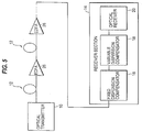
- FIG. 5 is a diagram illustrating a modification of the optical transmission system of FIG. 1, according to an embodiment of the present invention. More specifically, FIG. 5 shows an example in which the optical transmission system includes an optical amplifier-repeater that amplifies and relays an optical signal without regenerating it.
- Referring now to FIG. 5, many optical amplifier-repeaters each having an erbium doped fiber amplifier (EDFA) 26 are installed at intermediate points along the transmission line to relay the optical signal without regenerating it. As in the configuration of FIG. 1, fixed dispersion compensator 16 and variable dispersion compensator 18 are located in receiver section 14.
- In the examples of FIGS. 1 and 5, the order of fixed dispersion compensator 16 and variable dispersion compensator 18 may be interchanged. Alternatively, as shown in FIGS. 6 and 7, fixed dispersion compensator 16 and variable dispersion compensator 18 may be provided in a transmitter section 28 where optical transmitter 10 is located. Also, in that case, their order can be interchanged.
- Moreover, as shown in FIGS. 8 and 9, fixed dispersion compensator 16 and variable dispersion compensator 18 may be positioned so that one is in transmitter section 28 and the other is in receiver section 14.
- Further, as shown in FIG. 10, fixed dispersion compensator 16 and variable dispersion compensator 18 may also be provided in each optical amplifier-repeater 30. In FIG. 10, dispersion compensators 16 and 18 are provided in every optical amplifier-repeater 30, but these may be provided only in designated optical amplifier-repeaters. Further, in FIG. 10, a fixed dispersion compensator 16 and a variable dispersion compensator 18 are provided in receiver section 14, but, instead, they may be provided at the transmitting end.
- Alternatively, as shown in FIG. 11, only fixed dispersion compensator 16 may be provided in each optical amplifier-repeater 30 to perform coarse dispersion compensation, and variable dispersion compensator 18 may be provided only in receiver section 14 to perform fine dispersion compensation. In this case, variable dispersion compensator 18 may be provided at the transmitting end, not in receiver section 14. Also, more than one variable dispersion compensator 18 can be provided in the system. Further, fixed dispersion compensator 16 may be provided only in designated optical amplifier-repeaters, not in every optical amplifier-repeater 30.
- Therefore, according to embodiments of the present invention, a fixed dispersion compensator has a fixed dispersion amount, and coarsely compensates for dispersion in the transmission line. A variable dispersion compensator has a variable dispersion amount, and finely compensates for dispersion in the transmission line. Preferably, the fixed dispersion compensator and the variable dispersion compensator together provide a total amount of dispersion compensation substantially equal to the amount of dispersion of the transmission line.
- As indicated above, the fixed dispersion compensator provides coarse dispersion compensation, and the variable dispersion compensator provides fine dispersion compensation. As previously noted, "coarse" and "fine" are relative terms, where "coarse" refers to a larger amount of compensation than "fine". Therefore, the fixed dispersion compensator provides a relatively large amount of fixed compensation, and the variable dispersion compensator essentially "fine-tunes" the amount of compensation so that an accurate amount of total compensation is provided.
- Typically, the amount of compensation provided by the variable dispersion compensator will be less than or equal to 20% of that provided by the fixed dispersion compensator. As an example, in a 40 Gb/s transmission system, with an SMF transmission line of 50 km, the total dispersion is typically about 920 ps/nm. In this case, as an example, the fixed dispersion compensator could provide approximately -850 ps/nm of dispersion compensation, and the variable dispersion compensator could provide variable dispersion compensation in the range of 0 to -150 ps/nm. (Thus, -150/-850 ≈ 0.176, that is, less then or equal to 20%.)
- The above embodiments of the present invention are very effective in fine tuning the total amount of dispersion compensation to adjust for changes in environmental conditions, and changes in system specifications from the ideal specification. As an example, assume that a plurality of repeaters are supposed to be spaced along a transmission line at intervals of 50 km. If the repeaters are spaced at exactly 50 km intervals, an individual fixed dispersion compensator (such as a DCF) can be used by itself for each 50 km interval, to compensate for dispersion. Since the interval between repeaters is exactly 50 km, the exact amount of required dispersion can be determined and compensated for by the fixed dispersion compensator. However, in actuality, the interval between each repeater may not be exactly 50 km. For example, some repeaters may be spaced by 49 km, 51 km or 52 km. In this case, the variable dispersion compensator can be used to fine tune the total amount of compensation, to adjust for the changes in interval between repeaters. The variable dispersion compensator can also adjust, for example, for environmental changes over time. Such a variable dispersion compensation can be positioned at many different locations, such as in the transmitter, the receiver or in a repeater. Moreover, a plurality of such variable dispersion compensators can be provided to provide the required "fine-tuning".
- FIG. 12 is a diagram illustrating an optical transmission system, according to a further embodiment of the present invention. Referring now to FIG. 12, a discretely variable dispersion compensator 32 and a continuously variable dispersion compensator 34 are located in receiver section 14.
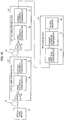
- FIG. 13 is a diagram illustrating discretely variable dispersion compensator 32. See also, A. Sano et al., ECOC' 96, Tud.3.5, which is incorporated herein by reference. Referring now to FIG. 13, discretely variable dispersion compensator 32 has a dispersion amount capable of being varied discontinuously. Discretely variable dispersion compensator 32 includes DCFs 36 having positive or negative dispersion values cascaded with 1x4 switches 38. In the illustrated example, the dispersion value can be set in increments of about 7 ps/nm between -183 ps/nm and +152 nm. The DCFs may be replaced by other devices, such as fiber gratings, that can set a fixed dispersion value. The present invention is not intended to be limited to this specific example, and many other configurations can be used for a discretely variable dispersion compensator. For example, virtually any number of DCFs and switches can be used to provide many different configurations, and elements other than DCFs and switches can be used.
- Continuously variable dispersion compensator 34 can be constructed, for example, from the previously mentioned PLC dispersion compensator or from a fiber grating provided with a stress gradient or temperature gradient.
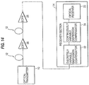
- FIG. 14 is a diagram illustrating a modification of the optical transmission system of FIG. 12, according to an embodiment of the present invention. More specifically, FIG. 14 shows an example of an optical amplifier-repeater transmission system. As in the configuration of FIG. 12, discretely variable dispersion compensator 32 and continuously variable dispersion compensator 34 are located in receiver section 14.
- In the examples of FIGS. 12 and 14, the order of discretely variable dispersion compensator 32 and continuously variable dispersion compensator 34 may be interchanged. Alternatively, as shown in FIGS. 15 and 16, these compensators may be provided in transmitter section 28. Also, in that case, their order can be interchanged. Further, as shown in FIGS. 17 and 18, discretely variable dispersion compensator 32 and continuously variable dispersion compensator 34 can be positioned so that one is in transmitter section 28 and the other in receiver section 14.
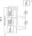
- As an additional example, as shown in FIG. 19, discretely variable dispersion compensator 32 and continuously variable dispersion compensator 34 may be provided in each optical amplifier-repeater 30. In FIG. 19, dispersion compensators 32 and 34 are provided in every optical amplifier-repeater 30, but may be provided only in designated optical amplifier-repeaters. Further, in FIG. 19, dispersion compensators 32 and 34 are provided in receiver section 14 but, instead, may be provided at the transmitting end.
- Alternatively, as shown in FIG. 20, only discretely variable dispersion compensator 32 may be provided in each optical amplifier-repeater 30 to perform coarse dispersion compensation, and continuously variable dispersion compensator 34 may be provided only in receiver section 14 to perform fine dispersion compensation. Moreover, instead, continuously variable dispersion compensator 34 may be provided at the transmitting end, not in receiver section 14. Further, discretely variable dispersion compensator 32 may be provided only in designated optical amplifier-repeaters, not in every optical amplifier-repeater 30.
- In the examples so far described, if the chromatic dispersion value including its variation along fiber length is already known from, for example, transmission waveform simulation, the locations of the dispersion compensators (fixed, continuously variable, and discretely variable) and their dispersion compensation amounts can be determined from the results of the simulation.
- On the other hand, if the chromatic dispersion of the transmission line is unknown, a transmission characteristic can be measured and the variable dispersion compensation values can be set in accordance with the measured characteristic, to optimize the transmission characteristics.
- More specifically, FIG. 21 is a diagram illustrating an optical transmission system, according to a further embodiment of the present invention. FIGS. 22-26 illustrate modifications of the optical transmission system of FIG. 21, according to an embodiment of the present invention.
- Referring now to FIGS. 21-26, a transmission characteristic measuring section 36 is preferably provided at the receiving end. Then, for example, during system power up, transmission characteristic measuring section 36 measures a transmission characteristic, and the dispersion compensation values are set so as to optimize the transmission characteristics. At this time, it is also possible to sweep the dispersion compensation amount while feeding back a control signal to the variable dispersion compensator (continuously variable, discretely variable), as shown in the figures. The bit-error rate, Q value, signal parity bit check, transmission waveform, etc. can be used as the transmission characteristic measured here.
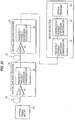
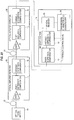
- FIG. 27 is a diagram illustrating an example of a detailed configuration of transmission characteristic measuring section 36 in which the Q value is measured and fed back as the transmission characteristic. Referring now to FIG. 27, a Q value measuring system 42 measures the Q value from an optical signal transmitted through the transmission line, and a microcomputer 40 uses the measured Q value to provide a feedback control signal.
- FIG. 28 is a flow chart illustrating the operation of microcomputer 40 shown in FIG. 27, according to an embodiment of the present invention. In FIG. 28, the Q value is measured during system power up while sweeping the dispersion value in the variable dispersion compensator (step 1000), and the dispersion value of the variable dispersion compensator is set to a value that maximizes the Q value (step 1002). During system operation, the Q value is measured, for example, at intervals of one hour (step 1004), and if the measured value is less than reference value (step 1006), the dispersion value in the variable dispersion compensator is incremented by one step (step 1008). If the Q value is improved, the process returns to the decision-making operation in step 1006. If the Q value is not improved, the dispersion value is then decremented by one step (step 1012), and the step 1012 is repeated until the Q value becomes equal to or greater than the reference value.
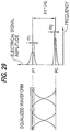
- FIG. 29 is a diagram showing the definition of the Q value measured by Q value measuring system 42, according to an embodiment of the present invention. That is
- µ1:
- average level during "emission"
- µ0:
- average level during "no emission"
- σ1:
- standard deviation of level during "emission"
- σ0:
- standard deviation of level during "no emission"
- The Q value is expressed using the signal level difference (signal amplitude) between emission and no emission as the numerator and the sum of the standard deviations of noise during emission and during no emission as the denominator. When a Gaussian distribution is assumed for the noise distribution, the bit-error rate given by the Q value defined in FIG. 29 agrees with the minimum value of the actually measured bit-error rate. Q value measuring system 42 is substantially identical in configuration to the optical receiver. That is, using a discrimination circuit having a reference voltage varying function, the discrimination level for an equalized waveform is varied up and down with respect to the optimum level to measure the bit-error rate, and by finding the intersection of the two straight lines obtained from the measurement, the minimum point of the bit-error rate is estimated, and the Q value can thus be obtained.
- The chromatic dispersion value of the received light itself may be measured as the transmission characteristic, and the variable dispersion compensator may be controlled so that the dispersion is set to an optimum value. The measurement of the chromatic dispersion value can be achieved by simply using a commercially available chromatic dispersion measuring device, or by incorporating the equivalent function into the transmitting and/or receiving equipment. Alternatively, the intensity of a specific frequency component in the baseband region, especially the intensity of a clock signal component, may be detected from the received signal, and the amount of dispersion compensation may be controlled so that the intensity reaches a maximum or a minimum, or a prescribed value, by using the relationship between the chromatic dispersion value and the intensity of the clock signal component.
- Furthermore, by controlling the amount of dispersion compensation while monitoring the transmission characteristic not only during system power up but also during system operation, control can be performed to accommodate the temperature dependence, temporal change, etc. of the chromatic dispersion value of the transmission line.
- The locations of the dispersion compensators 16, 18, 32, and 34 are not limited to the examples shown in FIGS. 21 to 26, but various modifications such as those described previously are possible.
- Several methods are possible for transmitting the feedback signal from the receiving end to each variable dispersion compensator. For example, a bidirectional communication method using a fiber transmission line or a low-speed electrical analog communication method can be used. Further, it is also possible to automatically set the amount of dispersion compensation to an optimum value by using a CPU or by centrally controlling the entire system. When there is a spare line having substantially the same dispersion condition and installation environment as the working line, a method can be employed in which the amount of dispersion compensation is first optimized using the spare line, and then, by referring to the result, the value is applied to the working line. With this method, the amount of dispersion compensation can be optimized without interrupting service.
- According to the above embodiments of the present invention, transmission speed can be increased while using already installed fiber transmission lines without modifications, and different types of fiber (SMF, DSF), different repeater spacings, and the variation of the chromatic dispersion value along fiber length can also be accommodated. These together serve to reduce the overall cost of the system.
- According to the above embodiments of the present invention, the chromatic dispersion of the optical transmission line is coarsely compensated for by using a fixed dispersion compensator or a discretely variable dispersion compensator according to the length of the transmission distance, and then the chromatic dispersion is finely compensated for by using a variable dispersion compensator or a continuously variable dispersion compensator. In this way, highly precise compensation can be made even when the required dispersion compensation amount is large, and large-capacity transmission is thus made possible.
- In the above embodiments of the present invention, an optical transmission system includes two types of dispersion compensators (such as a fixed dispersion compensator in combination with a variable dispersion compensator, or a discretely variable dispersion compensator in combination with a continuously variable dispersion compensator) . These different compensators can have many different positions in the optical transmission system. For example, one compensator can be in a transmitter section and the other compensator can be in a receiver section. Or, both compensators can be in the transmitter section, the receiver section or in a repeater.
- Often, both compensators can be included in the same housing. For example, when both compensators are in the receiver section, transmitter section or repeater, they are typically enclosed inside the same housing. For example, in the above drawings, such a housing would typically be represented by the "box" illustrating a specific element. For example, in FIG. 1, the "box" representing receiver section 14 could indicate a housing of the receiver section which includes the various elements enclosed therein. Similarly, for example, in FIG. 6, the "box" representing transmitter section 28 could indicate a housing of the transmitter section which includes the various elements enclosed therein.
- In addition, in many situations, both compensators are located in very close physical proximity, such as less than or equal to three meters. In some situations, the compensators can be located very close together so that there is no transmission line between the two compensators. This close situation can occur, for example, when both compensators are located in the transmitter section or the receiver section. When the compensators are located in close proximity, it is very easy to coordinate the combined compensation, and provide the appropriate amount of dispersion compensation fine-tuning.
- In the above embodiments of the present invention, the "receiver section" can simply be referred to as a "receiver". Similarly, the "transmission section" can simply be referred to as a "transmitter".
- Therefore, according to the above embodiments of the present invention, an apparatus compensates for dispersion in an optical transmission line. The apparatus includes a fixed dispersion compensator and a variable dispersion compensator. The fixed dispersion compensator has a fixed dispersion amount and coarsely compensates for the dispersion in the transmission line. The variable dispersion compensator has a variable dispersion amount and finely compensates for the dispersion in the transmission line.
- The fixed and variable dispersion compensators can be located at many positions. For example, one may be in a transmitter and the other may be in a receiver. Both may be in the transmitter and/or the receiver. One may be in either the transmitter or the receiver, with the other in an optical repeater positioned along the transmission line.
- There are many other possible configurations. For example, either a first fixed dispersion compensator or the variable dispersion compensator can be in the transmitter, with the other in the receiver. In this case, a second fixed dispersion compensator can be positioned in an optical repeater.
- Further, either a first fixed dispersion compensator or a first variable dispersion compensator can be in the transmitter, with the other in the receiver. In this case, a second fixed dispersion compensator and a second variable dispersion compensator can be positioned in an optical repeater.
- Moreover, a first fixed dispersion compensator can be in the transmitter while a second fixed dispersion compensator is in the receiver. In this case, a variable dispersion compensator can be at virtually any location in the optical transmission system.
- In addition, both the fixed dispersion compensator and the variable dispersion compensator can be enclosed inside the same housing. Further, in many situations, the fixed dispersion compensator and the variable dispersion compensator will be located physically close together, such as within or equal to three meters. Moreover, in some situations, the fixed dispersion compensator and the variable dispersion compensator can be directly connected to each other so that no portion of the transmission line is between the fixed dispersion compensator and the variable dispersion compensator.
- In addition, according to the above embodiments of the present invention, an apparatus includes a discretely variable dispersion compensator and a continuously variable dispersion compensator. The discretely variable dispersion compensator has a discontinuously variable dispersion amount and coarsely compensates for the dispersion in the transmission line. The continuously variable dispersion compensator has a continuously variable dispersion amount and finely compensates for dispersion in the transmission line.
- The discretely and continuously variable dispersion compensators can be located at many positions. For example, one may be in a transmitter and the other may be in a receiver. Both may be in the transmitter and/or the receiver. One may be in either the transmitter or the receiver, with the other in an optical repeater positioned along the transmission line.
- There are many other possible configurations. For example, either a first discretely variable dispersion compensator or the continuously variable dispersion compensator can be in the transmitter, with the other in the receiver. In this case, a second discretely variable dispersion compensator can be positioned in an optical repeater.
- Further, either a first discretely variable dispersion compensator or a first continuously variable dispersion compensator can be in the transmitter, with the other in the receiver. In this case, a second discretely variable dispersion compensator and a second continuously variable dispersion compensator can be positioned in an optical repeater.
- Moreover, a first discretely variable dispersion compensator can be in the transmitter while a second discretely variable dispersion compensator is in the receiver. In this case, a continuously variable dispersion compensator can be at virtually any location in the optical transmission system.
- In addition, both the discretely and continuously variable dispersion compensators can be enclosed inside the same housing. Further, in many situations, the discretely and continuously variable dispersion compensators will be located physically close together, such as within or equal to three meters. Moreover, in some situations, the discretely and continuously variable dispersion compensators can be directly connected to each other so that no portion of the transmission line is between the fixed dispersion compensator and the variable dispersion compensator.
- According to the above embodiments of the present invention, a compensator can be positioned at either the transmitting end or the receiving end of a transmission line. Generally, a transmission line can be considered as having two ends. One end is where a signal is provided to the transmission line to be transmitted through the transmission line, and the other end is where the signal is received from the transmission line.
- Although a few preferred embodiments of the present invention have been shown and described, it would be appreciated by those skilled in the art that changes may be made in these embodiments without departing from the principles and spirit of the invention, the scope of which is defined in the claims and their equivalents.
Claims (46)
- An apparatus which compensates for dispersion in an optical transmission line, comprising:a fixed dispersion compensator, having a fixed dispersion amount, coarsely compensating for the dispersion in the transmission line; anda variable dispersion compensator, having a variable dispersion amount, finely compensating for the dispersion in the transmission line.
- An apparatus as in claim 1, wherein the transmission line has a transmitting end and a receiving end, and the fixed dispersion compensator and the variable dispersion compensator are both positioned at the receiving end of the transmission line.
- An apparatus as in claim 1, wherein the transmission line has a transmitting end and a receiving end, and the fixed dispersion compensator and the variable dispersion compensator are both positioned at the transmitting end of the transmission line.
- An apparatus as in claim 1, further comprising:a receiver receiving an optical signal transmitted through the transmission line, wherein the fixed dispersion compensator and the variable dispersion compensator are both positioned in the receiver.
- An apparatus as in claim 1, further comprising:a transmitter transmitting an optical signal through the transmission line, wherein the fixed dispersion compensator and the variable dispersion compensator are both positioned in the transmitter.
- An apparatus as in claim 1, further comprising:a transmitter transmitting an optical signal through the transmission line; anda receiver receiving the optical signal transmitted through the transmission line, whereinone of the group consisting of the fixed dispersion compensator and the variable dispersion compensator is positioned in the transmitter, andthe other of the group consisting of the fixed dispersion compensator and the variable dispersion compensator is positioned in the receiver.
- An apparatus as in claim 1, whereinthe transmission line has a transmitting end and a receiving end,one of the group consisting of the fixed dispersion compensator and the variable dispersion compensator is positioned at the transmitting end of the transmission line, andthe other of the group consisting of the fixed dispersion compensator and the variable dispersion compensator is positioned at the receiving end of the transmission line.
- An apparatus as in claim 1, further comprising:an optical repeater, whereinthe transmission line includes a transmitting end and a receiving end, the optical repeater being positioned along the transmission line between the transmitting end and the receiving end,the fixed dispersion compensator includes first and second fixed dispersion compensators each having a fixed dispersion amount,one of the group consisting of the first fixed dispersion compensator and the variable dispersion compensator is positioned at the transmitting end of the transmission line,the other of the group consisting of the first fixed dispersion compensator and the variable dispersion compensator is positioned at the receiving end of the transmission line, andthe second fixed dispersion compensator is positioned in the optical repeater.
- An apparatus as in claim 1, further comprising:an optical repeater, whereinthe transmission line includes a transmitting end and a receiving end, the optical repeater being positioned along the transmission line between the transmitting end and the receiving end,the fixed dispersion compensator includes first and second fixed dispersion compensators each having a fixed dispersion amount,the variable dispersion compensator includes first and second variable dispersion compensators each having a variable dispersion amount,one of the group consisting of the first fixed dispersion compensator and the first variable dispersion compensator is positioned at the transmitting end of the transmission line,the other of the group consisting of the first fixed dispersion compensator and the first variable dispersion compensator is positioned at the receiving end of the transmission line, andthe second fixed dispersion compensator and the second variable dispersion compensator are both positioned in the optical repeater.
- An apparatus as in claim 1, wherein:the transmission line includes a transmitting end and a receiving end,the fixed dispersion compensator includes first and second fixed dispersion compensators each having a fixed dispersion amount, the first fixed dispersion compensator being positioned at the transmitting end of the transmission line and the second fixed dispersion compensator being positioned at the receiving end of the transmission line.
- An apparatus as in claim 1, further comprising:a transmitter transmitting an optical signal through the transmission line; anda receiver receiving the optical signal transmitted through the transmission line, whereinthe fixed dispersion compensator includes first and second fixed dispersion compensators each having a fixed dispersion amount, the first fixed dispersion compensator being positioned in the transmitter and the second fixed dispersion compensator being positioned in the receiver.
- An apparatus as in claim 1, further comprising:a measuring device measuring a transmission characteristic of the transmission line from an optical signal transmitted through the transmission line, wherein the variable dispersion amount of the variable dispersion compensator is set in accordance with the transmission characteristic measured by the measuring device.
- An apparatus as in claim 12, further comprising:a controller controlling the variable dispersion amount of the variable dispersion compensator in accordance with the transmission characteristic measured by the measuring device.
- An apparatus as in claim 1, wherein the variable dispersion amount of the variable dispersion compensator is less than or equal to 20% of the fixed dispersion amount of the fixed dispersion compensator.
- An apparatus as in claim 1, further comprising:a housing, the fixed dispersion compensator and the variable dispersion compensator both being enclosed inside the housing.
- An apparatus as in claim 4, wherein the receiver comprises a housing, the fixed dispersion compensator and the variable dispersion compensator both being enclosed inside the housing.
- An apparatus as in claim 5, wherein the transmitter comprises a housing, the fixed dispersion compensator and the variable dispersion compensator both being enclosed inside the housing.
- An apparatus as in claim 1, wherein the fixed dispersion compensator is a dispersion shifted fiber (DSF).
- An apparatus as in claim 1, wherein the fixed dispersion compensator and the variable dispersion compensator are physically separated by a distance of less than or equal to three meters.
- An apparatus as in claim 1, wherein the fixed dispersion compensator and the variable dispersion compensator are directly connected to each other so that no portion of the transmission line is between the fixed dispersion compensator and the variable dispersion compensator.
- An apparatus as in claim 1, wherein the transmission line requires a specific amount of dispersion compensation in accordance with the length of the transmission line, and the fixed dispersion compensator and the variable dispersion compensator together provide a total amount of dispersion compensation substantially equal to the required amount of dispersion compensation.
- An apparatus which compensates for dispersion in an optical transmission line, comprising:a discretely variable dispersion compensator, having a discontinuously variable dispersion amount, coarsely compensating for the dispersion in the transmission line; anda continuously variable dispersion compensator, having a continuously variable dispersion amount, finely compensating for dispersion in the transmission line.
- An apparatus as in claim 22, wherein the transmission line has a transmitting end and a receiving end, and the discretely variable dispersion compensator and the continuously variable dispersion compensator are both positioned at the receiving end of the transmission line.
- An apparatus as in claim 22, wherein the transmission line has a transmitting end and a receiving end, and the discretely variable dispersion compensator and the continuously variable dispersion compensator are both positioned at the transmitting end of the transmission line.
- An apparatus as in claim 22, further comprising:a receiver receiving an optical signal transmitted through the transmission line, wherein the discretely variable dispersion compensator and the continuously variable dispersion compensator are both positioned in the receiver.
- An apparatus as in claim 22, further comprising:a transmitter transmitting an optical signal through the transmission line, wherein the discretely variable dispersion compensator and the continuously variable dispersion compensator are both positioned in the transmitter.
- An apparatus as in claim 22, further comprising:a transmitter transmitting an optical signal through the transmission line; anda receiver receiving the optical signal transmitted through the transmission line, whereinone of the group consisting of the discretely variable dispersion compensator and the continuously variable dispersion compensator is positioned in the transmitter, andthe other of the group consisting of the discretely variable dispersion compensator and the continuously variable dispersion compensator is positioned in the receiver.
- An apparatus as in claim 22, whereinthe transmission line has a transmitting end and a receiving end,one of the group consisting of the discretely variable dispersion compensator and the continuously variable dispersion compensator is positioned at the transmitting end of the transmission line, andthe other of the group consisting of the discretely variable dispersion compensator and the continuously variable dispersion compensator is positioned at the receiving end of the transmission line.
- An apparatus as in claim 22, further comprising:an optical repeater, whereinthe transmission line includes a transmitting end and a receiving end, the optical repeater being positioned along the transmission line between the transmitting end and the receiving end,the discretely variable dispersion compensator includes first and second discretely variable dispersion compensators each having a discontinuously variable dispersion amount,one of the group consisting of the first discretely variable dispersion compensator and the continuously variable dispersion compensator is positioned at the transmitting end of the transmission line,the other of the group consisting of the first discretely variable dispersion compensator and the continuously variable dispersion compensator is positioned at the receiving end of the transmission line, andthe second discretely variable dispersion compensator is positioned in the optical repeater.
- An apparatus as in claim 22, further comprising:an optical repeater, whereinthe transmission line includes a transmitting end and a receiving end, the optical repeater being positioned along the transmission line between the transmitting end and the receiving end,the discretely variable dispersion compensator includes first and second discretely variable dispersion compensators each having a discontinuously variable dispersion amount,the continuously variable dispersion compensator includes first and second continuously variable dispersion compensators each having a continuously variable dispersion amount,one of the group consisting of the first discretely variable dispersion compensator and the first continuously variable dispersion compensator is positioned at the transmitting end of the transmission line,the other of the group consisting of the first discretely variable dispersion compensator and the first continuously variable dispersion compensator is positioned at the receiving end of the transmission line, andthe second discretely variable dispersion compensator and the second continuously variable dispersion compensator are both positioned in the optical repeater.
- An apparatus as in claim 22, wherein:the transmission line includes a transmitting end and a receiving end,the discretely variable dispersion compensator includes first and second discretely variable dispersion compensators each having a discontinuously variable dispersion amount, the first discretely variable dispersion compensator being positioned at the transmitting end of the transmission line and the second discretely variable dispersion compensator being positioned at the receiving end of the transmission line.
- An apparatus as in claim 22, further comprising:a transmitter transmitting an optical signal through the transmission line; anda receiver receiving the optical signal transmitted through the transmission line, whereinthe discretely variable dispersion compensator includes first and second discretely variable dispersion compensators each having a discontinuously variable dispersion amount, the first discretely variable dispersion compensator being positioned in the transmitter and the second discretely variable dispersion compensator being positioned in the receiver.
- An apparatus as in claim 22, further comprising:a measuring device measuring a transmission characteristic of the transmission line from an optical signal transmitted through the transmission line, wherein the discontinuously variable dispersion amount of the discretely variable dispersion compensator and the continuously variable dispersion amount of the continuously variable dispersion compensator are set in accordance with the transmission characteristic measured by the measuring device.
- An apparatus as in claim 33, further comprising:a controller controlling the discontinuously variable dispersion amount of the discretely variable dispersion compensator and the continuously variable dispersion amount of the continuously variable dispersion compensator in accordance with the transmission characteristic measured by the measuring device.
- An apparatus as in claim 22, wherein the continuously variable dispersion amount of the continuously variable dispersion compensator is less than or equal to 20% of the discontinuously variable dispersion amount of the discretely variable dispersion compensator.
- An apparatus as in claim 22, further comprising:a housing, the discretely variable dispersion compensator and the continuously variable dispersion compensator both being enclosed inside the housing.
- An apparatus as in claim 25, wherein the receiver comprises a housing, the discretely variable dispersion compensator and the continuously variable dispersion compensator both being enclosed inside the housing.
- An apparatus as in claim 26, wherein the transmitter comprises a housing, the discretely variable dispersion compensator and the continuously variable dispersion compensator both being enclosed inside the housing.
- An apparatus as in claim 22, wherein the discretely variable dispersion compensator is a dispersion shifted fiber (DSF).
- An apparatus as in claim 22, wherein the discretely variable dispersion compensator and the continuously variable dispersion compensator are physically separated by a distance of less than or equal to three meters.
- An apparatus as in claim 22, wherein the discretely variable dispersion compensator and the continuously variable dispersion compensator are directly connected to each other so that no portion of the transmission line is between the discretely variable dispersion compensator and the continuously variable dispersion compensator.
- An apparatus as in claim 22, wherein the transmission line requires a specific amount of dispersion compensation in accordance with the length of the transmission line, and the discretely variable dispersion compensator and the continuously variable dispersion compensator together provide a total amount of dispersion compensation substantially equal to the required amount of dispersion compensation.
- An apparatus comprising:a transmission line having a corresponding amount of dispersion;a fixed dispersion compensator, having a fixed dispersion amount, coarsely compensating for dispersion in the transmission line; anda variable dispersion compensator, having a variable dispersion amount, finely compensating for dispersion in the transmission line, wherein the fixed dispersion compensator and the variable dispersion compensator together provide a total amount of dispersion compensation substantially equal to the amount of dispersion of the transmission line.
- An apparatus as in claim 43 wherein the variable dispersion amount of the variable dispersion compensator is less than or equal to 20% of the fixed dispersion amount of the fixed dispersion compensator.
- A method of compensating for dispersion in an optical transmission line having a corresponding amount of dispersion, comprising the steps of:coarsely compensating for dispersion in the transmission line with a fixed dispersion amount; andfinely compensating for dispersion in the transmission line with a variable compensation amount, wherein the steps of coarsely compensating and finely compensating together provide a total amount of dispersion compensation substantially equal to the amount of dispersion of the transmission line.
- A method as in claim 45, wherein the step of finely compensating provides an amount of dispersion compensation which is less than or equal to 20% of the amount of dispersion compensation provided by the step of coarsely compensating.
Applications Claiming Priority (3)
| Application Number | Priority Date | Filing Date | Title |
|---|---|---|---|
| JP9243877A JPH1188260A (en) | 1997-09-09 | 1997-09-09 | Spread compensating device of optical transmission line |
| JP24387797 | 1997-09-09 | ||
| JP243877/97 | 1997-09-09 |
Publications (2)
| Publication Number | Publication Date |
|---|---|
| EP0902558A2 true EP0902558A2 (en) | 1999-03-17 |
| EP0902558A3 EP0902558A3 (en) | 2004-01-28 |
Family
ID=17110320
Family Applications (1)
| Application Number | Title | Priority Date | Filing Date |
|---|---|---|---|
| EP98104699A Withdrawn EP0902558A3 (en) | 1997-09-09 | 1998-03-16 | Dispersion compensation apparatus including a fixed dispersion compensator for coarse compensation and a variable dispersion compensator for fine compensation |
Country Status (4)
| Country | Link |
|---|---|
| US (3) | US6320687B1 (en) |
| EP (1) | EP0902558A3 (en) |
| JP (1) | JPH1188260A (en) |
| CN (1) | CN1173495C (en) |
Cited By (14)
| Publication number | Priority date | Publication date | Assignee | Title |
|---|---|---|---|---|
| WO2000011815A1 (en) * | 1998-08-20 | 2000-03-02 | Ciena Corporation | Dispersion compensating element having an adjustable dispersion |
| WO2001029993A1 (en) * | 1999-10-18 | 2001-04-26 | Scc Special Communication Cables Gmbh & Co Kg | Device for compensating the chromatic dispersion in an optical waveguide |
| EP1117200A2 (en) * | 2000-01-11 | 2001-07-18 | Fujitsu Limited | Apparatus and method for compensating chromatic dispersion in an optical transmission line |
| WO2002015441A2 (en) * | 2000-08-15 | 2002-02-21 | Chorum Technologies Lp | Dispersion compensation for high speed optical transmission systems |
| EP1223694A2 (en) * | 2001-01-10 | 2002-07-17 | Fujitsu Limited | Dispersion compensating method, dispersion compensating apparatus and optical transmission system |
| EP1257076A1 (en) * | 2000-01-31 | 2002-11-13 | Sumitomo Electric Industries, Ltd. | Wavelength dispersion compensation module and optical transmission system including the same |
| US6574404B2 (en) | 2000-01-31 | 2003-06-03 | Sumitomo Electric Industries, Ltd. | Choromatic dispersion compensating module and optical transmission system using the same |
| EP1431785A1 (en) * | 2002-12-18 | 2004-06-23 | Alcatel | A method for controlling the transmission performance of an optical transmission line, an optical transmission system and a control facility therefore |
| US6907200B2 (en) | 1999-12-03 | 2005-06-14 | Sumitomo Electric Industries, Ltd. | Dispersion compensating module, line switching apparatus and optical communication system |
| US7006770B2 (en) * | 2000-05-29 | 2006-02-28 | Fujitsu Limited | Optical receiving station, optical communication system, and dispersion controlling method |
| WO2008135965A1 (en) * | 2007-05-02 | 2008-11-13 | Eci Telecom Ltd. | Technique for compensating undesired effects in optical links of an optical communication network |
| EP2007042A2 (en) * | 2006-03-10 | 2008-12-24 | ZTE Corporation | Wavelength division multiplexing system and residual dispersion compensating device and method thereof |
| US20140328556A1 (en) * | 2011-03-15 | 2014-11-06 | Medlumics S.L. | Integrated System for Active Equalization of Chromatic Dispersion |
| EP2214333B1 (en) * | 2009-01-30 | 2017-03-08 | Fujitsu Limited | Distortion compensating apparatus, optical receiving apparatus, and optical transmitting and receiving system |
Families Citing this family (82)
| Publication number | Priority date | Publication date | Assignee | Title |
|---|---|---|---|---|
| JP3748652B2 (en) * | 1997-02-27 | 2006-02-22 | 富士通株式会社 | Optical transmission system using inline amplifier |
| JPH1188260A (en) * | 1997-09-09 | 1999-03-30 | Fujitsu Ltd | Spread compensating device of optical transmission line |
| DE19812078A1 (en) * | 1998-03-19 | 1999-09-23 | Siemens Ag | Signal quality monitoring method for optical transmission path |
| US6456411B1 (en) | 1998-03-30 | 2002-09-24 | Fujitsu Limited | Method of setting signal wavelength in optical transmission system |
| ITTO980362A1 (en) * | 1998-04-28 | 1999-10-28 | Cselt Centro Studi Lab Telecom | PROCEDURE FOR TRANSMISSION OF OPTICAL SIGNALS WITH COMPENSATION OF CHROMATIC DISPERSION BY MEANS OF OPTICAL FIBER RETICLES WITH VARIABLE PITCH |
| JP2000031900A (en) * | 1998-07-08 | 2000-01-28 | Fujitsu Ltd | Method for optical fiber communication and terminal station device and system used for execution of the method |
| US6674557B1 (en) * | 1998-09-21 | 2004-01-06 | Corning Incorporated | Wavelength division multiplexing systems |
| US6609220B2 (en) * | 1998-09-30 | 2003-08-19 | Ando Electric Co., Ltd. | Method of manufacturing Q-value and device therefor |
| JP2000236297A (en) * | 1999-02-16 | 2000-08-29 | Fujitsu Ltd | Method and system for optical transmission applied with dispersion compensation |
| FR2791835B1 (en) * | 1999-03-31 | 2001-06-29 | Cit Alcatel | DEVICE AND METHOD FOR COMPENSATING FOR POLARIZATION DISPERSION IN AN OPTICAL TRANSMISSION SYSTEM |
| JP4180738B2 (en) * | 1999-06-14 | 2008-11-12 | 株式会社東芝 | Digital signal quality monitoring method and communication apparatus using the method |
| US6690886B1 (en) * | 1999-12-22 | 2004-02-10 | Nortel Networks Limited | Suppression of four-wave mixing in ultra dense WDM optical communication systems through optical fibre dispersion map design |
| JP2001211122A (en) * | 2000-01-26 | 2001-08-03 | Nec Corp | Device and method for monitoring dispersion compensation, device and method for controlling dispersion, optical receiver, and optical transmission system |
| AU2001260987A1 (en) * | 2000-02-18 | 2001-08-27 | Corning Incorporated | Electrical detector for adaptive control of chromatic dispersion in optical systems |
| US20010028760A1 (en) * | 2000-03-03 | 2001-10-11 | Yaffe Henry H. | Methods and apparatus for compensating chromatic and polarization mode dispersion |
| GB0011143D0 (en) * | 2000-05-10 | 2000-06-28 | Ilotron Limited | Dispersion compensation |
| US6832050B1 (en) * | 2000-07-19 | 2004-12-14 | At&T Corp. | Method and system for reducing intra-channel nonlinear effects in highly dispersed optical pulse transmission |
| JP4592887B2 (en) | 2000-08-07 | 2010-12-08 | 富士通株式会社 | Method and system for compensating chromatic dispersion |
| ITMI20010442A1 (en) * | 2001-03-02 | 2002-09-02 | Marconi Comm Spa | OPTICAL COMMUNICATION SYSTEM AND APPARATUS FOR COMPENSATION OR EMULATION OF PMD EFFECTS |
| US20030026533A1 (en) * | 2001-08-03 | 2003-02-06 | Yochay Danziger | Configurable dispersion management device |
| JP2003163642A (en) * | 2001-11-28 | 2003-06-06 | Fujitsu Ltd | Optical transmitter and optical transmission module |
| KR20030044110A (en) * | 2001-11-28 | 2003-06-09 | 삼성전자주식회사 | Optical preamplifier having one stage configuration |
| US7577366B2 (en) * | 2002-01-07 | 2009-08-18 | Fujitsu Limited | Selectable dispersion enhancement |
| JP3994264B2 (en) * | 2002-01-31 | 2007-10-17 | 横河電機株式会社 | OTDR output signal filtering method for chromatic dispersion distribution measuring instrument |
| US20030185573A1 (en) * | 2002-03-28 | 2003-10-02 | Fells Julian A. | Optical transmission systems |
| US6931186B2 (en) * | 2002-04-05 | 2005-08-16 | Alcatel | Chromatic dispersion compensation module |
| FR2854517B1 (en) * | 2003-04-29 | 2005-08-05 | Cit Alcatel | CHROMATIC DISPERSION COMPENSATION MODULE |
| US6965738B2 (en) * | 2002-04-16 | 2005-11-15 | Eiselt Michael H | Chromatic dispersion compensation system and method |
| JP3923373B2 (en) * | 2002-05-31 | 2007-05-30 | 富士通株式会社 | Automatic dispersion compensation device and compensation method |
| US7460745B2 (en) * | 2002-06-04 | 2008-12-02 | Pivotal Decisions Llc | Configurable dispersion compensation trimmer |
| US20040037568A1 (en) * | 2002-08-20 | 2004-02-26 | Evangelides Stephen G. | Optical repeater employed in an optical communication system having a modular dispersion map |
| US20040096223A1 (en) * | 2002-08-20 | 2004-05-20 | Red Sky Systems, Inc. | Modular dispersion map for an optical communication system |
| DE10243141B4 (en) * | 2002-09-17 | 2006-05-11 | Siemens Ag | Method for transmitting optical polarization multiplexed signals |
| US7421207B2 (en) * | 2002-12-13 | 2008-09-02 | Pivotal Decisions Llc | Single fiber duplex optical transport |
| US7782778B2 (en) | 2002-12-24 | 2010-08-24 | Samir Satish Sheth | Apparatus and method for fibre channel distance extension embedded within an optical transport system |
| JP3864338B2 (en) * | 2003-01-31 | 2006-12-27 | 富士通株式会社 | Dispersion compensation apparatus and dispersion compensation control method |
| JP4576094B2 (en) | 2003-03-03 | 2010-11-04 | 富士通株式会社 | Wavelength division multiplexing optical repeater transmission method and repeater |
| JP4520097B2 (en) * | 2003-03-06 | 2010-08-04 | ソフトバンクテレコム株式会社 | Dispersion compensation method for optical communication path with dynamic control |
| JP4138557B2 (en) | 2003-03-31 | 2008-08-27 | 富士通株式会社 | Chromatic dispersion compensation control system |
| JP4468656B2 (en) | 2003-05-27 | 2010-05-26 | 株式会社日立製作所 | Signal waveform deterioration compensator |
| US7197252B2 (en) * | 2003-07-31 | 2007-03-27 | Sumitomo Electric Industries, Ltd. | Optical transmitter and optical communication system |
| JP2005159928A (en) * | 2003-11-28 | 2005-06-16 | Hitachi Communication Technologies Ltd | Automatic dispersion compensating method |
| US20050226613A1 (en) * | 2004-03-30 | 2005-10-13 | Lutz Raddatz | Net chromatic dispersion measurement and compensation method and system for optical networks |
| JP4280665B2 (en) | 2004-03-31 | 2009-06-17 | 富士通株式会社 | Dispersion compensation method and compensation node device |
| JP4484608B2 (en) * | 2004-07-14 | 2010-06-16 | 富士通株式会社 | Optical transmission system control method |
| FR2879863A1 (en) * | 2004-12-21 | 2006-06-23 | Highwave Optical Tech | Optical signal`s chromatic dispersion compensating device for e.g. field of optical telecommunication through optical guides, has switches to switch optical path of signal between two paths situated between inlet and outlet |
| WO2006106973A1 (en) * | 2005-03-31 | 2006-10-12 | Nec Corporation | Optical communication method, optical communication apparatus, and optical communication system |
| US8798483B2 (en) * | 2005-12-20 | 2014-08-05 | Zte Corporation | Apparatus and method for selfadapting dispersion compensation |
| JP4686370B2 (en) * | 2006-01-30 | 2011-05-25 | 株式会社日立製作所 | WDM transmission system |
| JP2008060682A (en) * | 2006-08-29 | 2008-03-13 | Fujitsu Ltd | Dispersion compensator and dispersion compensating method |
| CN100447600C (en) * | 2006-12-30 | 2008-12-31 | 北京交通大学 | Compensation method for polarization mode dispersion by using high birefringence uniform fiber grating and structure thereof |
| WO2009008042A1 (en) * | 2007-07-06 | 2009-01-15 | Fujitsu Limited | Communication network and method for design |
| JP5181770B2 (en) * | 2008-03-27 | 2013-04-10 | 富士通株式会社 | Optical transmission system |
| CN102308499B (en) | 2009-02-04 | 2015-01-21 | 日本电气株式会社 | Optical communication system and optical communication method |
| EP2249493B1 (en) * | 2009-05-05 | 2013-12-18 | Alcatel Lucent | Method and equipment for operating a coherent optical packet receiver |
| CN102484532B (en) * | 2009-09-02 | 2015-08-12 | 富士通株式会社 | Communication system, dispersion slope imparting unit and communication means |
| CN102111224B (en) * | 2010-12-31 | 2015-04-08 | 武汉虹拓新技术有限责任公司 | Broadband-adjustable dispersion compensation method and dispersion compensation device |
| JP5786427B2 (en) * | 2011-04-13 | 2015-09-30 | 富士通株式会社 | Skew reduction method and optical transmission system |
| US20120328294A1 (en) * | 2011-06-23 | 2012-12-27 | Verizon Patent And Licensing Inc. | High speed passive optical network architecture |
| US9178641B2 (en) * | 2011-07-06 | 2015-11-03 | Infinera Corporation | Suppression of non-linear effects in low dispersion optical fibers |
| US10404397B2 (en) | 2015-12-23 | 2019-09-03 | Adva Optical Networking Se | Wavelength division multiplexed telecommunication system with automatic compensation of chromatic dispersion |
| KR102415308B1 (en) * | 2016-02-25 | 2022-07-01 | 한국전자통신연구원 | Analog optical transmission system |
| US20170272163A1 (en) * | 2016-03-17 | 2017-09-21 | Nikola Alic | Compensation of nonlinear impairment in fiber optic links by including distributed variations of waveguide dispersive properties |
| US10122460B2 (en) | 2017-01-13 | 2018-11-06 | Adva Optical Networking Se | Method and apparatus for automatic compensation of chromatic dispersion |
| US10205552B2 (en) | 2017-01-20 | 2019-02-12 | Cox Communications, Inc. | Optical communications module link, systems, and methods |
| US10516922B2 (en) | 2017-01-20 | 2019-12-24 | Cox Communications, Inc. | Coherent gigabit ethernet and passive optical network coexistence in optical communications module link extender related systems and methods |
| US11502770B2 (en) | 2017-01-20 | 2022-11-15 | Cox Communications, Inc. | Optical communications module link extender, and related systems and methods |
| EP3656069A1 (en) * | 2017-07-21 | 2020-05-27 | Telefonaktiebolaget LM Ericsson (publ) | Chromatic dispersion compensation |
| US10993003B2 (en) | 2019-02-05 | 2021-04-27 | Cox Communications, Inc. | Forty channel optical communications module link extender related systems and methods |
| US11290184B2 (en) * | 2019-03-01 | 2022-03-29 | Molex, Llc | Switchable dispersion compensating module |
| US10999658B2 (en) | 2019-09-12 | 2021-05-04 | Cox Communications, Inc. | Optical communications module link extender backhaul systems and methods |
| US11317177B2 (en) * | 2020-03-10 | 2022-04-26 | Cox Communications, Inc. | Optical communications module link extender, and related systems and methods |
| US11689308B2 (en) * | 2020-03-10 | 2023-06-27 | Cox Communications, Inc. | Optical communications module link extender, and related systems and methods |
| US11271670B1 (en) | 2020-11-17 | 2022-03-08 | Cox Communications, Inc. | C and L band optical communications module link extender, and related systems and methods |
| US11146350B1 (en) | 2020-11-17 | 2021-10-12 | Cox Communications, Inc. | C and L band optical communications module link extender, and related systems and methods |
| WO2022168303A1 (en) * | 2021-02-08 | 2022-08-11 | 日本電信電話株式会社 | Optical communication system, control device, and quality compensation method |
| US11323788B1 (en) | 2021-02-12 | 2022-05-03 | Cox Communications, Inc. | Amplification module |
| US11689287B2 (en) | 2021-02-12 | 2023-06-27 | Cox Communications, Inc. | Optical communications module link extender including ethernet and PON amplification |
| US11523193B2 (en) | 2021-02-12 | 2022-12-06 | Cox Communications, Inc. | Optical communications module link extender including ethernet and PON amplification |
| US20230084066A1 (en) * | 2021-09-14 | 2023-03-16 | Huawei Technologies Co., Ltd. | System and method for dispersion compensation in fibered optical communication paths |
| US11637637B1 (en) * | 2021-12-23 | 2023-04-25 | Equinix, Inc. | Hybrid compensation of chromatic dispersion in optical networks |
| US11962345B2 (en) * | 2022-01-21 | 2024-04-16 | Precision Optical Technologies, Inc. | Configurable dispersion compensation in a pluggable optical transceiver |
Citations (4)
| Publication number | Priority date | Publication date | Assignee | Title |
|---|---|---|---|---|
| US5430568A (en) * | 1992-12-01 | 1995-07-04 | Scientific-Atlanta, Inc. | Optical communications system for transmitting information signals having different wavelengths over a same optical fiber |
| EP0700178A2 (en) * | 1994-08-02 | 1996-03-06 | Fujitsu Limited | Optical transmission system with optimisation of transmission conditions |
| US5608562A (en) * | 1994-05-25 | 1997-03-04 | Lucent Technologies Inc. | Optical communications system with adjustable dispersion compensation |
| DE19602433A1 (en) * | 1996-01-24 | 1997-07-31 | Siemens Ag | Dispersion compensating circuit arrangement for multiplexed optical transmission system |
Family Cites Families (12)
| Publication number | Priority date | Publication date | Assignee | Title |
|---|---|---|---|---|
| JPH06216467A (en) | 1993-01-19 | 1994-08-05 | Hitachi Ltd | Semiconductor light-dispersion compensator |
| US5365362A (en) * | 1993-09-10 | 1994-11-15 | At&T Bell Laboratories | Ultra-high capacity non-soliton optical transmission using optical phase conjugation |
| US5411566A (en) * | 1994-06-08 | 1995-05-02 | At&T Corp. | Optical fiber spatial mode converter using periodic core deformation |
| JPH08256106A (en) | 1995-03-17 | 1996-10-01 | Fujitsu Ltd | Decentralization compensation device for optical amplification submarine transmission system |
| JP3606628B2 (en) * | 1995-03-31 | 2005-01-05 | 富士通株式会社 | Optical transmission system using SMF transmission line |
| JPH0946318A (en) * | 1995-08-01 | 1997-02-14 | Fujitsu Ltd | Wavelength multiplexed optical transmission system and optical transmitter to be used for same |
| JP3262312B2 (en) | 1995-09-05 | 2002-03-04 | 日本電信電話株式会社 | Optical dispersion equalizer |
| JPH09218314A (en) | 1996-02-13 | 1997-08-19 | Fujitsu Ltd | Optimum dispersion compensating device for receiving terminal station for optical communication |
| JP3522044B2 (en) | 1996-04-19 | 2004-04-26 | 富士通株式会社 | Optical transmission system |
| CA2208393C (en) * | 1996-06-21 | 2004-01-06 | Youichi Akasaka | Wavelength division multiplex communication link for optical transmission |
| JPH1188260A (en) * | 1997-09-09 | 1999-03-30 | Fujitsu Ltd | Spread compensating device of optical transmission line |
| US5887093A (en) * | 1997-09-12 | 1999-03-23 | Lucent Technologies Incorporated | Optical fiber dispersion compensation |
-
1997
- 1997-09-09 JP JP9243877A patent/JPH1188260A/en active Pending
-
1998
- 1998-02-10 US US09/021,578 patent/US6320687B1/en not_active Expired - Lifetime
- 1998-03-16 EP EP98104699A patent/EP0902558A3/en not_active Withdrawn
- 1998-03-19 CN CNB981057292A patent/CN1173495C/en not_active Expired - Fee Related
-
2001
- 2001-09-13 US US09/950,709 patent/US6909851B2/en not_active Expired - Lifetime
-
2005
- 2005-04-22 US US11/111,783 patent/US20050185964A1/en not_active Abandoned
Patent Citations (4)
| Publication number | Priority date | Publication date | Assignee | Title |
|---|---|---|---|---|
| US5430568A (en) * | 1992-12-01 | 1995-07-04 | Scientific-Atlanta, Inc. | Optical communications system for transmitting information signals having different wavelengths over a same optical fiber |
| US5608562A (en) * | 1994-05-25 | 1997-03-04 | Lucent Technologies Inc. | Optical communications system with adjustable dispersion compensation |
| EP0700178A2 (en) * | 1994-08-02 | 1996-03-06 | Fujitsu Limited | Optical transmission system with optimisation of transmission conditions |
| DE19602433A1 (en) * | 1996-01-24 | 1997-07-31 | Siemens Ag | Dispersion compensating circuit arrangement for multiplexed optical transmission system |
Cited By (26)
| Publication number | Priority date | Publication date | Assignee | Title |
|---|---|---|---|---|
| US6259845B1 (en) | 1998-08-20 | 2001-07-10 | Ciena Corporation | Dispersion compensating element having an adjustable dispersion |
| WO2000011815A1 (en) * | 1998-08-20 | 2000-03-02 | Ciena Corporation | Dispersion compensating element having an adjustable dispersion |
| WO2001029993A1 (en) * | 1999-10-18 | 2001-04-26 | Scc Special Communication Cables Gmbh & Co Kg | Device for compensating the chromatic dispersion in an optical waveguide |
| US6907200B2 (en) | 1999-12-03 | 2005-06-14 | Sumitomo Electric Industries, Ltd. | Dispersion compensating module, line switching apparatus and optical communication system |
| EP1117200A2 (en) * | 2000-01-11 | 2001-07-18 | Fujitsu Limited | Apparatus and method for compensating chromatic dispersion in an optical transmission line |
| US7397981B2 (en) | 2000-01-11 | 2008-07-08 | Fujitsu Limited | Apparatus and method of compensating for wavelength dispersion of optical transmission line |
| EP1117200A3 (en) * | 2000-01-11 | 2004-11-10 | Fujitsu Limited | Apparatus and method for compensating chromatic dispersion in an optical transmission line |
| EP1257076A1 (en) * | 2000-01-31 | 2002-11-13 | Sumitomo Electric Industries, Ltd. | Wavelength dispersion compensation module and optical transmission system including the same |
| US6574404B2 (en) | 2000-01-31 | 2003-06-03 | Sumitomo Electric Industries, Ltd. | Choromatic dispersion compensating module and optical transmission system using the same |
| EP1257076A4 (en) * | 2000-01-31 | 2006-05-10 | Sumitomo Electric Industries | Wavelength dispersion compensation module and optical transmission system including the same |
| US7321736B2 (en) | 2000-05-29 | 2008-01-22 | Fujitsu Limited | Optical receiving station, optical communication system, and dispersion controlling method |
| US7006770B2 (en) * | 2000-05-29 | 2006-02-28 | Fujitsu Limited | Optical receiving station, optical communication system, and dispersion controlling method |
| WO2002015441A3 (en) * | 2000-08-15 | 2002-07-18 | Chorum Technologies Lp | Dispersion compensation for high speed optical transmission systems |
| WO2002015441A2 (en) * | 2000-08-15 | 2002-02-21 | Chorum Technologies Lp | Dispersion compensation for high speed optical transmission systems |
| EP1223694A3 (en) * | 2001-01-10 | 2004-06-16 | Fujitsu Limited | Dispersion compensating method, dispersion compensating apparatus and optical transmission system |
| EP1223694A2 (en) * | 2001-01-10 | 2002-07-17 | Fujitsu Limited | Dispersion compensating method, dispersion compensating apparatus and optical transmission system |
| EP1928108A1 (en) * | 2001-01-10 | 2008-06-04 | Fujitsu Limited | Dispersion compensating method, dispersion compensating apparatus and optical transmission system |
| US6871024B2 (en) | 2001-01-10 | 2005-03-22 | Fujitsu Limited | Dispersion compensating method, dispersion compensating apparatus and optical transmission system |
| EP1431785A1 (en) * | 2002-12-18 | 2004-06-23 | Alcatel | A method for controlling the transmission performance of an optical transmission line, an optical transmission system and a control facility therefore |
| US8886050B2 (en) | 2006-03-10 | 2014-11-11 | Zte Corporation | Wavelength division multiplexing system, method and device for its residual dispersion compensation |
| EP2007042A2 (en) * | 2006-03-10 | 2008-12-24 | ZTE Corporation | Wavelength division multiplexing system and residual dispersion compensating device and method thereof |
| EP2007042A4 (en) * | 2006-03-10 | 2012-03-07 | Zte Corp | Wavelength division multiplexing system and residual dispersion compensating device and method thereof |
| WO2008135965A1 (en) * | 2007-05-02 | 2008-11-13 | Eci Telecom Ltd. | Technique for compensating undesired effects in optical links of an optical communication network |
| EP2214333B1 (en) * | 2009-01-30 | 2017-03-08 | Fujitsu Limited | Distortion compensating apparatus, optical receiving apparatus, and optical transmitting and receiving system |
| US20140328556A1 (en) * | 2011-03-15 | 2014-11-06 | Medlumics S.L. | Integrated System for Active Equalization of Chromatic Dispersion |
| US9310563B2 (en) * | 2011-03-15 | 2016-04-12 | Medlumics S.L. | Integrated system for active equalization of chromatic dispersion |
Also Published As
| Publication number | Publication date |
|---|---|
| US20020003646A1 (en) | 2002-01-10 |
| US6320687B1 (en) | 2001-11-20 |
| CN1211119A (en) | 1999-03-17 |
| CN1173495C (en) | 2004-10-27 |
| US20050185964A1 (en) | 2005-08-25 |
| JPH1188260A (en) | 1999-03-30 |
| US6909851B2 (en) | 2005-06-21 |
| EP0902558A3 (en) | 2004-01-28 |
Similar Documents
| Publication | Publication Date | Title |
|---|---|---|
| US6320687B1 (en) | Dispersion compensation apparatus including a fixed dispersion compensator for coarse compensation and a variable dispersion compensator for fine compensation | |
| EP0626768B1 (en) | High capacity optical fiber network and fiber | |
| EP0554714B1 (en) | Dispersion compensating devices and systems | |
| Ramachandran et al. | All-fiber grating-based higher order mode dispersion compensator for broad-band compensation and 1000-km transmission at 40 Gb/s | |
| US7440662B2 (en) | Compensating fiber for cumulated chromatic dispersion and chromatic dispersion slope | |
| Refi | Optical fibers for optical networking | |
| EP0959374A1 (en) | Dispersion flat optical fiber | |
| US6496631B2 (en) | Optical transmission line and optical transmission system including the same | |
| JP5112582B2 (en) | Fiber for chromatic dispersion compensation of NZ-DSF fiber with positive chromatic dispersion | |
| Vorbeck et al. | Dispersion and dispersion slope tolerance of 160-Gb/s systems, considering the temperature dependence of chromatic dispersion | |
| EP1049275B1 (en) | Dispersion compensation module | |
| US7164829B2 (en) | Optical fiber, optical transmission line and optical communications system | |
| EP0882334B1 (en) | Dispersion compensation in optical fibre transmission | |
| US6917743B2 (en) | Optical fiber, optical transmission line, and optical communications system | |
| JP2002182053A (en) | Optical fiber for in-line compensation of chromatic dispersion in optical fiber having positive chromatic dispersion | |
| JPH08316912A (en) | Wavelength dispersion compensator and wavelength dispersion compensation optical communication system | |
| EP1576747B1 (en) | Optical transmission system using an optical phase conjugation device | |
| Raja et al. | An optimized design for non-zero dispersion shifted fiber with reduced nonlinear effects for future optical networks | |
| US6476950B1 (en) | Method for optical signal transmission with chromatic dispersion compensation through chirped optical fibre gratings, and optical communication system using the method | |
| JP2004530345A (en) | Optical transmission line and optical transmission system using the same | |
| US6684017B1 (en) | Optical transmission line and optical transmission system including the same | |
| Tawade et al. | A novel analysis of single mode fiber for reduction of chromatic dispersion using dispersion compensated fiber | |
| AU728349B2 (en) | High capacity optical fiber network | |
| Vishwakarma et al. | A Review Paper on a Simulation Approach for Dispersion Compensation in Optical System with a FBG | |
| Viljoen | Improving DWDM transmission systems by using dispersion management |
Legal Events
| Date | Code | Title | Description |
|---|---|---|---|
| PUAI | Public reference made under article 153(3) epc to a published international application that has entered the european phase |
Free format text: ORIGINAL CODE: 0009012 |
|
| AK | Designated contracting states |
Kind code of ref document: A2 Designated state(s): AT BE CH DE DK ES FI FR GB GR IE IT LI LU MC NL PT SE |
|
| AX | Request for extension of the european patent |
Free format text: AL;LT;LV;MK;RO;SI |
|
| PUAL | Search report despatched |
Free format text: ORIGINAL CODE: 0009013 |
|
| AK | Designated contracting states |
Kind code of ref document: A3 Designated state(s): AT BE CH DE DK ES FI FR GB GR IE IT LI LU MC NL PT SE |
|
| AX | Request for extension of the european patent |
Extension state: AL LT LV MK RO SI |
|
| RIC1 | Information provided on ipc code assigned before grant |
Ipc: 7G 02B 6/34 B Ipc: 7H 04B 10/18 A |
|
| 17P | Request for examination filed |
Effective date: 20040226 |
|
| 17Q | First examination report despatched |
Effective date: 20040414 |
|
| AKX | Designation fees paid |
Designated state(s): DE FR GB |
|
| STAA | Information on the status of an ep patent application or granted ep patent |
Free format text: STATUS: THE APPLICATION IS DEEMED TO BE WITHDRAWN |
|
| 18D | Application deemed to be withdrawn |
Effective date: 20051103 |