EP0902416B1 - Method and device for recognizing a speech input during an announcement - Google Patents
Method and device for recognizing a speech input during an announcement Download PDFInfo
- Publication number
- EP0902416B1 EP0902416B1 EP98114986A EP98114986A EP0902416B1 EP 0902416 B1 EP0902416 B1 EP 0902416B1 EP 98114986 A EP98114986 A EP 98114986A EP 98114986 A EP98114986 A EP 98114986A EP 0902416 B1 EP0902416 B1 EP 0902416B1
- Authority
- EP
- European Patent Office
- Prior art keywords
- signal
- announcement
- adaptation
- adder
- elog
- Prior art date
- Legal status (The legal status is an assumption and is not a legal conclusion. Google has not performed a legal analysis and makes no representation as to the accuracy of the status listed.)
- Expired - Lifetime
Links
Images


Classifications
-
- G—PHYSICS
- G10—MUSICAL INSTRUMENTS; ACOUSTICS
- G10L—SPEECH ANALYSIS OR SYNTHESIS; SPEECH RECOGNITION; SPEECH OR VOICE PROCESSING; SPEECH OR AUDIO CODING OR DECODING
- G10L15/00—Speech recognition
- G10L15/20—Speech recognition techniques specially adapted for robustness in adverse environments, e.g. in noise, of stress induced speech
-
- G—PHYSICS
- G10—MUSICAL INSTRUMENTS; ACOUSTICS
- G10L—SPEECH ANALYSIS OR SYNTHESIS; SPEECH RECOGNITION; SPEECH OR VOICE PROCESSING; SPEECH OR AUDIO CODING OR DECODING
- G10L15/00—Speech recognition
- G10L15/22—Procedures used during a speech recognition process, e.g. man-machine dialogue
- G10L2015/223—Execution procedure of a spoken command
Definitions
- Speech recognition systems make it easy to use Realize services via public communication networks. So a user of a voice-controlled announcement system request information via his voice input, that are stored in the announcement system. Furthermore, he can Transactions, e.g. Money transfers or orders To run. Finds between the user and the announcement system human-machine communication takes place that is in favor of designed the user the more convenient and effective, ever they better in their process of human-human communication is approximated. Communication between people draws is known, among other things, by the fact that one Interlocutors aimed at the information of the other responds. It also speaks in a human-human communication usually only one interlocutor, so that the other can register what has been said.
- announcement Information For information services by voice-controlled announcement systems are offered, are to be conveyed via the announcement Information organized in a kind of tree structure.
- answer the user makes a first announcement with his voice input of the announcement system.
- the announcement system the user chooses the next announcement from so-called announcement menu from which the tree structure of the reflects stored information.
- the user communicates with targeted voice inputs in response to the Voice announcements of the announcement menu as long as with the announcement system, until it gives him the information he wants. To this Way, the time it takes to get the one you want Obtaining information from the announcement system, comparatively be kept short.
- the invention solves this problem according to claims 1-17 by the method for Recognize a pause during an announcement in which an digital announcement signal and a digital voice input signal is averaged over a predetermined averaging period. It become signal differences for time windows of predetermined length of the average speech input signal and the average announcement signal determined. The signal differences are consecutive Time windows are fed to a first digital filter, this taking into account a first adaptation function
- Pulse measure determines which one besides a basic part Share of changes in the signal difference of a time window contains.
- the signal differences of successive time windows will continue to be a second digital filter supplied, taking into account a second adaptation function determined a basic measure, which essentially the basic part of the signal difference of a time window reproduces.
- a detector signal is generated if that Pulse size larger than the basic size plus a specified one Is threshold.
- successive Time windows differed whether they both Announcement information and voice input information included or not.
- This distinction is currently too processing time window based on the determined Pulse measure and the determined background measure taken.
- the Time windows determine the temporal resolution with which a simultaneous occurrence of announcement and voice input recorded can be.
- the length of the time window can equal the duration of the averaging his. This can be the case, for example, during processing encoded data may be advantageous if this is in time frames given length.
- the determination of the pulse measure and the background measure is the determination of the Signal difference between averaged voice input signal and averaged announcement signal. The signal difference is in their chronological course at times through maximum values, i.e. characterized by pulses, to which the announcement and the Voice input occur simultaneously.
- the temporal Course of the pulse measure essentially the temporal behavior the signal difference is reflected, the temporal Course of the basic dimension essentially solely from the announcement certainly.
- the comparison of the pulse measure with the basic measure for a given time window allows time ranges, in which the announcement and the speech input occur at the same time, to distinguish from time periods in which only the Announcement is made.
- the synchronous determination of pulse measure and The background measure of the current time frame is given by the Consideration of the first and second adaptation functions allows. Since the pulse measure for each individual time window compared to the background measure plus the specified threshold and the evaluation signal is generated, a simultaneous appearance of announcement and voice input quickly and reliably determined.
- the method according to the invention is not based on the use limited in a voice-controlled announcement system, but can be used for any system where a simultaneous Occurrence of two speech signals is to be detected. For example, it can be used to control hands-free telephones used by echo cancellation units, at which "double talking" in a known manner based on Volume comparison of the near and far speakers determined becomes.
- An advantageous development of the invention consists in that the absolute values of the announcement signal of the voice input signal be averaged. Instead of the absolute values, too the squares of the values of the announcement signal and the speech input signal be averaged. Is advantageous as a signal difference the difference in the logarithm of the average speech input signal and the logarithm of the averaged announcement signal used.
- logarithmic signals which is the dynamic range of the speech signals underlying data are well adapted.
- Another advantageous embodiment of the invention exists in that the signal difference caused by the first digital Filter is processed, a first and a second Processing branch of the first digital filter supplied is that the processing branch connected in series first adder, a multiplier and a has second adder, which outputs the pulse measure that the pulse measure with a delay of at least the duration of one Time window and the second adder is added and subtracted at the first adder that the second processing branch connected in series an adder and an adapter has that on the adder the delayed pulse measure is subtracted and as a result one first auxiliary variable is determined that in the adapter from the first auxiliary variable a first adaptation variable according to predetermined first adaptation function is determined and that this adaptation variable in the first processing branch on the multiplication element is used as a multiplier.
- the first auxiliary variable corresponds to the change in the pulse measurements consecutive time slots, i.e. it gives a measure for the short-term fluctuations in the signal difference.
- Dependency of the first auxiliary variable is in the second processing branch determines the first adaptation size, which in turn in the first processing branch for determining the pulse measure of the current time window is used.
- the settling time the first digital filter is for the duration of a time window limited so that the pulse measure after switching on can be determined without significant delay.
- the method is advantageously further developed in that the signal difference caused by the second digital filter is processed, a first and a second processing branch of the second digital filter is supplied that the first processing branch connected in series a first Adder, a multiplier, a second adder and a third adder, which is the basic dimension plus the specified threshold value indicates that the basic dimension with a delay of at least the duration of a time window returned and added at the second adder and the first adder is subtracted that the second Processing branch connected in series an adder and an adapter has that on the adder the delayed Subtracted the basic dimension and as a result a second auxiliary variable it is determined that in the adapter from the second Auxiliary size a second adaptation size according to the given second adaptation function is determined and that this adaptation size in the first processing branch on the multiplier is used as a multiplier.
- a second digital filter can be used, which differs from distinguishes the first digital filter only in that it taking into account the second adaptation function second adaptation base size determined.
- essentially identical digital filters are used are compared, so that the circuit complexity is relatively low with known methods.
- the threshold is advantageously between 6dB and 10dB. If the background dimension of the current time window for a Comparison with the pulse measure increased by this threshold, this increases the reliability with which a simultaneous Occurrence of announcement and voice input can be determined can.
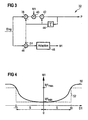
- the announcement system 10 contains in addition to an announcement device 12 and a speech recognition device 14 as functionally essential components Detector device 16, an echo canceller 18 and a damping device 20.
- the announcement system 10 includes furthermore a multiplier 22, the inputs of which the announcement device 12 and the damping device 20 are connected and the output of the echo canceller 18 and controls the detector device 16. Further leads the output of the multiplier 22 to one Output 23 of the announcement system 10, via which the announcement User is fed.
- the announcement is based on a digital announcement signal An that in a known manner by means of a D / A converter (not shown) into an analog one and then audible to the user Signal is converted.
- voice input of the user through A-D conversion of one of the voice input corresponding analog signal, a digital voice input signal Sp generated that the announcement system 10 via an input 24 is supplied.
- the announcement signal On and the voice input signal Sp are fed to the detector unit 16, which in to be described, a simultaneous occurrence of Announcement and voice input.
- the detector device 16 inputs announcement and voice input Detector signal Dt with the logic value 1, while for the In the event that announcement and voice input do not coincide superimpose, the detector signal Dt assumes the logic value 0.
- the echo canceller is used via the detector signal Dt 18 and the damping device 20 controlled.
- the volume of the Announcement can be varied. Will be inside the detector device 16 a simultaneous occurrence of voice input and Announcement detected, the damping device 20 with the Logic value 1 of the detector signal Dt driven. In this Case becomes a damping factor in the damping device 20 d set to a setpoint that is a medium damping the announcement of 12 dB, for example, by the Multiplier 22 is supplied and this from the Announcement device 12 originating announcement signal accordingly the damping factor d is reduced.
- a counter (not shown) started when a predetermined count value is reached the damping device 20 causes the damping factor d increase and thus the volume of the announcement continues to increase reduce.
- the volume of the announcement is controlled by the damping device 20 varies in stages, because the damping factor d only then is set to another value when the counter within the damping device 20 the predetermined count has reached. This gradually varying the volume the announcement On can cause noise, e.g. pops cause.
- the setpoints of the damping factor to be set d are therefore within the damping device 20th filtered in a known manner by means of digital low passports, so that instead of the step-like setpoint specification "smooth" setpoint function results by appropriate Transition times of the respective transitions between two successive ones Setpoints of the damping factor d marked is.
- the echo canceller 18 has the task of Exempt voice input from an announcement echo. This will generated in that the announcement about a in Fig. 1 with EP designated echo path from the output 23 to the input 24 of the Announcement system 10 is transmitted and there in the to be processed Voice input signal Sp is received.
- the Transmission properties of the echo path EP i.e. his Transfer function, from the echo canceller 18 reproduced in a rapidly converging adaptation process.
- the echo canceller 18 is by the Detector signal Dt controlled and generated from the announcement signal To that fed to him by the multiplier 22 an echo signal Ae simulated by the announcement echo, that is subtracted from the speech signal Sp at the adder 25 becomes.
- the speech recognition device 14 is responsible for this digital signal of the speech input freed from the announcement echo to disposal. In the speech recognition device 14 can the relevant message content in a known manner voice input.
- the detector device 16 contains in parallel switched an announcement averaging element 26 and an input averaging element 28. These components are with an adder 30 linked, arranged in parallel with a digital Follow pulse filter 32 and a digital basic filter 34.
- the pulse filter 32 and the basic filter 34 are with a Evaluation unit 36 connected.
- the invention is illustrated below using an example in which the announcement signal On and the voice input signal Sp are each a sequence of samples taken by Sampling the corresponding analog signals at a sampling rate of 8 kHz are generated.
- the announcement averaging member 26 determined from the announcement signal An a medium energy content ⁇ An> by for an appropriate number of samples of the announcement signal to an absolute value formation, logarithmization and averaging is performed.
- the number of Samples are set at 80 for this example, so that the announcement signal An in this example over an averaging period of 10 ms is averaged.
- the averaging can e.g. done in a known manner by low-pass filtering.
- On Average energy content ⁇ An> of the announcement signal An thus recorded is fed to the adder 30.
- the pulse filter 32 or the basic filter 34 generate in a manner to be described from the Difference Elog a pulse measure P or a basic measure G, which the Evaluation unit 36 are supplied.
- the evaluation unit 36 is the pulse measure P with the basic measure G plus a predetermined Threshold value OF compared. If the pulse measure P is larger than the basic dimension G increased by the threshold value OF, see above the evaluation unit 36 outputs the evaluation signal Dt with the Logic value 1 from which the simultaneous occurrence of announcement and Displays voice input.
- the digital pulse filter 32 is shown that from the difference Elog of the current time window the pulse measure P generated.
- the pulse filter 32 contains two processing branches. In the first processing branch are connected in series first adder 38, a multiplier 40 and a second adder 42 included. The second adder 42 is followed by a delay element 44, the Output connected to the input of the first adder 38 is.
- the delay element 44 generates a signal delay T, which corresponds to the length of a time window.
- the digital filters work together a clock frequency of 8 kHz, so that the signal delay T and thus the length of a time window is set at 125 ns is.
- the second processing branch there is an adder 46 and an adapter 48 connected in series. The Input of adder 46 is also connected to the output of Delay element 44 connected.
- the first auxiliary variable D1 is formed by subtracting the pulse measure P delayed by T, ie the pulse measure P of the time window preceding the current time window, from the difference Elog of the current time window on the adder 28. If one designates the time window currently to be processed with n and the previous time window, ie a signal delay T previously processed, with n-1, then D1 can be written as (1) D1 (n) Elog (n) - P (n-1).
- the auxiliary variable D1 gives a measure of the change in the pulse measures P of two successive time windows. From the auxiliary variable D1 according to the relationship (1), the adaptation element 48 generates the adaptation variable M1 according to the characteristic curve 50 according to FIG. 4, which is supplied to the multiplication element 40. In the first processing branch, the pulse measure P (n-1) of the last processed time window n-1 is subtracted from the difference Elog (n) of the current time window n at the adder 38. The result of this subtraction is multiplied at the multiplication element 40 by the adaptation variable M1.
- the pulse measure P (n) of the time window n currently to be processed is the sum of two complementary weights Shares.
- the two shares are weighted using the Adaptation size M1, which generally has values between 0 and 1 can accept.
- the second part M1 dominates for large values of M1 ⁇ Elog (n), so that the pulse measure P (n) of the current time window n essentially by the difference Elog (n) of the current Time window n is given.
- the pulse measure P (n) remains for small values of D1 of the current time window n compared to the pulse measure P (n-1) of the previous frame n-1 almost unchanged since the first Adaptation function in this value range from D1 small values assumes close to 0.
- D1 increase the value of the adaptation size M1 too, so that the contribution of the difference Elog (n) des current time window n becomes larger and the pulse measure P (n) of the current time window n follows the difference Elog.
- the effect of the digital pulse filter 32 according to FIG. 3 is accordingly in that strong pulses over time the difference Elog can be detected while slight fluctuations in Elog to be smoothed.
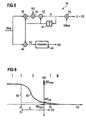
- the first adaptation function with the characteristic curve 50 according to FIG. 4 can be approximated by a rectangular function which assumes a minimum value M1 min for magnitude values of D1 smaller than a predetermined amplitude value s and a maximum value M1 max for magnitude values of D1 greater than the predetermined amplitude value s.
- the predetermined amplitude value s is 10
- the minimum value M1 min is 1/32
- the maximum value M1 max is 1/2.
- the rectangular function is represented in FIG. 4 by a rectangular characteristic curve 52 (dashed line).
- the minimum value M1 min is shown exaggeratedly large in FIG. 4.
- the amplitude value s is set in such a way that the pulse measure P remains essentially unaffected by slight fluctuations in the difference Elog, but strong pulses of Elog are reflected in the course of P over time, which is illustrated later with reference to FIGS. 10 and 11.
- the digital basic filter 34 is shown, the from the difference Elog (n) of the current time window n das Basic dimension G is generated.
- the basic filter 34 is essentially constructed in the same way as the Pulsf ter 14, so that on a detailed description of its structure at this point can be dispensed with.
- the components of the basic filter 34 which correspond to the components of the pulse filter 32 according to FIG. 2, are in Fig. 5 with the reference numerals of the components of the pulse filter 32.
- the digital basic filter 34 additionally contains a further adder 54, which on Output of the first processing branch is arranged. On the adder 54 becomes that of the adder 42 output basic dimension G and a predetermined threshold OF added and the result of this addition is output.
- the Adding the threshold value OF ensures a safety margin of the basic measure G compared to the pulse measure P.
- the Threshold value OF is set so that the safety distance is about 6 dB to 10 dB.
- the basic filter 34 also differs from the pulse filter 32 in that a second adaptation variable M2 which is different from the first adaptation variable M1 and which is supplied to the multiplication element 40 is determined in the adaptation element 48.
- the determination of the second adaptation variable M2 is based on a second adaptation function, the characteristic curve 56 of which is shown as a solid line in FIG. 6.
- the characteristic curve 56 falls from a higher level to a lower level near 0 within a transition region II, which predominantly contains negative values of D2.
- the second adaptation variable M2 determined according to the characteristic curve 56 becomes in the first Processing branch used to calculate the basic dimension G (n) of the current time window n.
- the basic dimension G (n-1) of the last processed time window n-1 is subtracted from the difference Elog (n) of the current time window n and the result of this subtraction is multiplied at the multiplication element 40 by the second adaptation variable M2.
- the result of this multiplication and the basic dimension G (n-1) of the last processed time window n-1 are added to the adder 42.
- Adaptation size M2 are weighted complementarily to each other.
- M2 can generally take values between 0 and 1. ever The larger M2 is, the less it bears due to the basic size G (n-1) of the previous time window n-1 given portion (1-M2) ⁇ G (n-1) to the basic dimension G (n) of the current time window n at. Conversely, as M2 decreases, the contribution M2 ⁇ Elog (n) reduced.
- equation (4) in connection with Fig. 6 the basic dimension G (n) for positive values of D2 (area III) essentially by the basic dimension G (n-1) of the previous one Time window n-1 given, since M2 for positive values of D2 Assumes values close to 0.
- the basic dimension G therefore remains at one sudden increase in difference Elog, i.e. on insertion the speech input during the announcement, essentially unchanged.
- D2 i.e. for bigger ones Values of M2
- I in FIG. 6 I denotes according to the equation (3) an area where the difference elog (n) versus the basic dimension G (n-1) drops significantly. This is the case as soon as the speech input is ended during the announcement.
- the second adaptation function can be approximated by a step function.
- a step-shaped characteristic curve 58 is shown in dashed lines in FIG. 6 as an approximation to the second adaptation function characterized by the characteristic curve 56.
- the adaptation variable M2 takes a maximum value M2 max in region I, which is given by values of D2 smaller than a predetermined negative value S1, in region II, which by values of D2 greater than or equal to the predetermined negative value S1 and less than or equal to a predetermined positive value S2, an intermediate value M2 zw and in the area III, which is given by values of D2 greater than the predetermined positive value S2, a minimum value M2 min .
- the second adaptation variable M2 is determined in accordance with the characteristic curve 58.
- the characteristic curve 58 is equal to -20 by S1, S2 equal to 10, M2 max is equal to 1/16, M2 zw equal to 1/128 and M2 characterized min is equal to 1/32768.
- the method of operation of the detector device 16 just explained 7 to 12 using the example of a concrete announcement and a concrete speech input illustrated.
- the voice input is the time of the announcement partially overlaid.
- 7 is the time course of the Announcement signal An, which corresponds to an announcement "Siemens", in shown in a time range from 0 to 1.8 s.
- the speech signal Sp is shown in FIG won by A-D conversion of a voice input "Mueller" has been.
- FIGS. 7 and 8 there is one partial temporal overlay of the announcement signal An and the Speech input signals Sp before.
- the echo path EP (see FIG. 1) is in this example by an over the entire frequency range largely constant attenuation of approx.
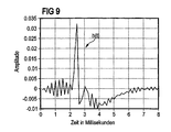
- the announcement signal On and the speech input signal Sp become after absolute value formation, logarithmization and averaging the signal difference Elog formed, their temporal Course is shown in Fig. 10.
- Fig. 10 Like a comparison of the Fig. 10 with Figs. 7 and 8 shows the signal difference Elog to great values at the times when the announcement signal On and overlay the voice input signal Sp. kick the announcement signal An, on the other hand, is the temporal Course of the signal difference Elog largely constant.
- the digital filters 32 and 34 generate from the signal difference Elog the pulse measure P and the basic measure in the manner described above G plus the predetermined threshold OF, whose temporal Course is shown in Fig. 11. At the times when if the announcement occurs alone, this is around the threshold OF Enlarged basic size, i.e.
- the threshold value OF is approximately 10 dB is set.
- the detector signal Dt with logic value 0 becomes voice input is output as shown in FIG.
- the occurrence of announcement and voice input exceeds the pulse measure P is the sum of the basic measure G and the threshold value OF, and the detector device 16 outputs the detector signal Dt with logic value 1, as also shown in FIG. 12 is.
- FIGS. 7, 8 and 12 show that the Detector device 16 a simultaneous occurrence of Announcement and voice input reliable and with negligible Delay detected.
Description
Spracherkennungssysteme ermöglichen es, benutzerfreundliche Dienste über öffentliche Kommunikationsnetze zu realisieren. So kann ein Benutzer eines sprachgesteuerten Ansagesystems über seine Spracheingabe beispielsweise Informationen abfragen, die in dem Ansagesystem gespeichert sind. Ferner kann er Transaktionen, z.B. Geldüberweisungen oder Bestellungen ausführen. Zwischen dem Benutzer und dem Ansagesystem findet dabei eine Mensch-Maschine-Kommunikation statt, die sich für den Benutzer um so bequemer und effektiver gestaltet, je besser sie in ihrem Ablauf einer Mensch-Mensch-Kommunikation angenähert ist. Eine Kommunikation zwischen Menschen zeichnet sich bekanntlich unter anderem dadurch aus, daß der eine Gesprächspartner auf die Information des anderen gezielt antwortet. Darüber hinaus spricht bei einer Mensch-Mensch-Kommunikation in der Regel nur ein Gesprächspartner, so daß der andere das Gesagte registrieren kann.Speech recognition systems make it easy to use Realize services via public communication networks. So a user of a voice-controlled announcement system request information via his voice input, that are stored in the announcement system. Furthermore, he can Transactions, e.g. Money transfers or orders To run. Finds between the user and the announcement system human-machine communication takes place that is in favor of designed the user the more convenient and effective, ever they better in their process of human-human communication is approximated. Communication between people draws is known, among other things, by the fact that one Interlocutors aimed at the information of the other responds. It also speaks in a human-human communication usually only one interlocutor, so that the other can register what has been said.
Bei Informationsdiensten, die von sprachgesteuerten Ansagesystemen angeboten werden, sind die über die Ansage zu vermittelnden Informationen in einer Art Baumstruktur organisiert. Um die gewünschte Information zu erhalten, antwortet der Benutzer mit seiner Spracheingabe auf eine erste Ansage des Ansagesystems. In Abhängigkeit der Spracheingabe des Benutzers wählt das Ansagesystem die nächste Ansage aus einem sogenannten Ansage-Menü aus, das die Baumstruktur der gespeicherten Information wiederspiegelt. Der Benutzer kommuniziert mit gezielten Spracheingaben als Antwort auf die Sprachansagen des Ansage-Menüs solange mit dem Ansagesystem, bis dieses ihm die gewünschte Information liefert. Auf diese Weise kann die Zeit, die benötigt wird, um die gewünschte Information von dem Ansagesystem zu erhalten, vergleichsweise kurz gehalten werden. For information services by voice-controlled announcement systems are offered, are to be conveyed via the announcement Information organized in a kind of tree structure. To get the requested information, answer the user makes a first announcement with his voice input of the announcement system. Depending on the voice input of the The announcement system the user chooses the next announcement from so-called announcement menu from which the tree structure of the reflects stored information. The user communicates with targeted voice inputs in response to the Voice announcements of the announcement menu as long as with the announcement system, until it gives him the information he wants. To this Way, the time it takes to get the one you want Obtaining information from the announcement system, comparatively be kept short.
Bei bekannten Ansagesystemen stellt es sich jedoch als Nachteil dar, daß der Benutzer bis zum Ende der jeweiligen Ansage warten muß, bis er die Spracheingabe und so die gewünschte Wahl innerhalb des Ansage-Menüs vornehmen darf, da das Ansagesystem mit der Ansage fortfährt, ohne die Spracheingabe des Benutzers zu registrieren. Bei gleichzeitig auftretender Ansage und Spracheingabe, auch "double talking" genannt, geht so ein Teil der von dem Benutzer aufgesprochenen Sprachinformation verloren, so daß die Kommunikation zwischen Benutzer und Ansagesystem gestört ist. Derartige Kommunikationsstörungen treten bei bekannten Ansagesystemen häufig auf. So geht aus einem Feldversuch, wiedergegeben in "A voice-activated telephone exchange system and its field trial", S. Yamamoto, K. Takeda, N. Inone, S. Kuroiwa, M. Naitoh, Proceedings of 2nd IEEE Workshop on Interactive Voice Technology for Telecommunications Applications, Kyoto, Japan 26-27 Sept. 1994, p. 21-26, hervor, daß über 60 % der Benutzer bereits vor dem Ende der Ansage mit dem Sprechen begonnen haben. Um die eben erläuterten Kommunikationsstörungen zu vermeiden, muß ein Ansagesystem in die Lage versetzt werden, ein gleichzeitiges Auftreten von Ansage und Spracheingabe zu erkennen.In known announcement systems, however, it is a disadvantage represents that the user until the end of each announcement must wait until he has the voice input and so the desired one May make a choice within the announcement menu, because the announcement system continues with the announcement without the voice input of Register user. When occurring simultaneously Announcement and voice input, also called "double talking", goes such a part of the speech information spoken by the user lost, so communication between users and announcement system is disturbed. Such communication problems occur frequently with known announcement systems. This is how it works from a field trial, reproduced in "A voice-activated telephone exchange system and its field trial ", S. Yamamoto, K. Takeda, N. Inone, S. Kuroiwa, M. Naitoh, Proceedings of 2nd IEEE Workshop on Interactive Voice Technology for Telecommunications Applications, Kyoto, Japan Sept. 26-27, 1994, p. 21-26, shows that over 60% of users before Started speaking at the end of the announcement. Just about that To avoid the described communication problems, a Announcement system will be able to use a simultaneous Recognize the appearance of announcement and voice input.
Ein weiterer Stand der Technik ist aus der Patentschrift US-A-5548681 bekannt. In dieser Patentschrift wird ein sprachgesteuertes Ansagesystem beschrieben, bei dem eine Spracheingabe eines Benutzers bereits während einer Ansage erfolgen kann.Another prior art is known from US-A-5548681. In this Patent specification describes a voice-controlled announcement system in which a Voice input from a user can already take place during an announcement.
Es ist Aufgabe der Erfindung, ein Verfahren und eine Einrichtung für ein sprachgesteuertes Ansagesystem anzugeben, das bzw. die es erlaubt, eine Spracheingabe während einer Ansage sicher und schnell zu erkennen.It is an object of the invention, a method and a device for a voice-operated announcement system to indicate that or which allows voice input during an announcement recognizable safely and quickly.
Die Erfindung löst diese Aufgabe gemäss den Ansprüchen 1-17 durch das Verfahren zum Erkennen einer Sprechpause während einer Ansage, bei dem ein digitales Ansagesignal und ein digitales Spracheingabesignal über eine vorgegebene Mittelungsdauer gemittelt wird. Es werden für Zeitfenster vorbestimmter Länge Signaldifferenzen von gemitteltem Spracheingabesignal und gemitteltem Ansagesignal ermittelt. Die Signaldifferenzen aufeinanderfolgender Zeitfenster werden einem ersten digitalen Filter zugeführt, das unter Berücksichtigung einer ersten Adaptionsfunktion ein The invention solves this problem according to claims 1-17 by the method for Recognize a pause during an announcement in which an digital announcement signal and a digital voice input signal is averaged over a predetermined averaging period. It become signal differences for time windows of predetermined length of the average speech input signal and the average announcement signal determined. The signal differences are consecutive Time windows are fed to a first digital filter, this taking into account a first adaptation function
Pulsmaß ermittelt, welches neben einem Basisanteil einen Änderungsanteil an der Signaldifferenz eines Zeitfensters enthält. Die Signaldifferenzen aufeinanderfolgender Zeitfenster werden weiterhin einem zweiten digitalen Filter zugeführt, das unter Berücksichtigung einer zweiten Adaptionsfunktion ein Grundmaß ermittelt, welches im wesentlichen den Basisanteil an der Signaldifferenz eines Zeitfensters wiedergibt. Für das gleichzeitige Auftreten der Ansage und der Spracheingabe wird ein Detektorsignal erzeugt, wenn das Pulsmaß größer als das Grundmaß plus einem vorgegebenem Schwellenwert ist.Pulse measure determines which one besides a basic part Share of changes in the signal difference of a time window contains. The signal differences of successive time windows will continue to be a second digital filter supplied, taking into account a second adaptation function determined a basic measure, which essentially the basic part of the signal difference of a time window reproduces. For the simultaneous appearance of the announcement and the speech input a detector signal is generated if that Pulse size larger than the basic size plus a specified one Is threshold.
Bei dem erfindungsgemäßen Verfahren werden aufeinanderfolgende Zeitfenster dahingehend unterschieden, ob sie sowohl Ansageinformation als auch Spracheingabeinformation enthalten oder nicht. Diese Unterscheidung wird für das aktuell zu verarbeitende Zeitfenster auf der Grundlage des ermittelten Pulsmaßes und des ermittelten Hintergrundmaßes getroffen. Die Zeitfenster bestimmen die zeitliche Auflösung, mit der ein gleichzeitiges Auftreten von Ansage und Spracheingabe erfaßt werden kann. Die Länge der Zeitfenster kann gleich der Mittelungsdauer sein. Dies kann beispielsweise bei der Verarbeitung codierter Daten vorteilhaft sein, wenn diese in Zeitrahmen vorgegebener Länge vorliegen. Der Ermittlung des Pulsmaßes und des Hintergrundmaßes liegt die Bestimmung der Signaldifferenz von gemitteltem Spracheingabesignal und gemitteltem Ansagesignal zugrunde. Die Signaldifferenz ist in ihrem zeitlichen Verlauf zu den Zeiten durch Maximalwerte, d.h. durch Pulse gekennzeichnet, zu denen die Ansage und die Spracheingabe gleichzeitig auftreten. Während der zeitliche Verlauf des Pulsmaßes im wesentlichen das zeitliche Verhalten der Signaldifferenz wiederspiegelt, wird der zeitliche Verlauf des Grundmaßes im wesentlichen allein von der Ansage bestimmt. Der Vergleich des Pulsmaßes mit dem Grundmaß für ein vorgegebenes Zeitfenster erlaubt es mithin, Zeitbereiche, in denen die Ansage und die Spracheingabe zugleich auftreten, von Zeitbereichen zu unterscheiden, in denen allein die Ansage erfolgt. Die synchrone Ermittlung von Pulsmaß und Hintergrundmaß des aktuellen Zeitrahmens wird durch die Berücksichtigung der ersten und der zweiten Adaptionsfunktion ermöglicht. Da für jedes einzelne Zeitfenster das Pulsmaß mit dem Hintergrundmaß plus dem vorgegebenen Schwellenwert verglichen und das Auswertesignal erzeugt wird, kann ein gleichzeitiges Auftreten von Ansage und Spracheingabe schnell und zuverlässig ermittelt werden.In the method according to the invention, successive Time windows differed whether they both Announcement information and voice input information included or not. This distinction is currently too processing time window based on the determined Pulse measure and the determined background measure taken. The Time windows determine the temporal resolution with which a simultaneous occurrence of announcement and voice input recorded can be. The length of the time window can equal the duration of the averaging his. This can be the case, for example, during processing encoded data may be advantageous if this is in time frames given length. The determination of the pulse measure and the background measure is the determination of the Signal difference between averaged voice input signal and averaged announcement signal. The signal difference is in their chronological course at times through maximum values, i.e. characterized by pulses, to which the announcement and the Voice input occur simultaneously. During the temporal The course of the pulse measure essentially the temporal behavior the signal difference is reflected, the temporal Course of the basic dimension essentially solely from the announcement certainly. The comparison of the pulse measure with the basic measure for a given time window allows time ranges, in which the announcement and the speech input occur at the same time, to distinguish from time periods in which only the Announcement is made. The synchronous determination of pulse measure and The background measure of the current time frame is given by the Consideration of the first and second adaptation functions allows. Since the pulse measure for each individual time window compared to the background measure plus the specified threshold and the evaluation signal is generated, a simultaneous appearance of announcement and voice input quickly and reliably determined.
Das erfindungsgemäße Verfahren ist nicht auf die Verwendung in einem sprachgesteuerten Ansagesystem beschränkt, sondern kann für jedes System angewendet werden, bei dem ein gleichzeitiges Auftreten von zwei Sprachsignalen zu erfassen ist. Beispielsweise kann es bei Freisprechtelefonen zur Ansteuerung von Echounterdrückungseinheiten eingesetzt werden, bei denen "double talking" in bekannter Weise auf der Basis von Lautstärkevergleichen der Nah- und Fernsprecher ermittelt wird.The method according to the invention is not based on the use limited in a voice-controlled announcement system, but can be used for any system where a simultaneous Occurrence of two speech signals is to be detected. For example, it can be used to control hands-free telephones used by echo cancellation units, at which "double talking" in a known manner based on Volume comparison of the near and far speakers determined becomes.
Eine vorteilhafte Weiterbildung der Erfindung besteht darin, daß die Absolutwerte des Ansagesignals des Spracheingabesignals gemittelt werden. Anstelle der Absolutwerte können auch die Quadrate der Werte des Ansagesignals und des Spracheingabesignals gemittelt werden. Vorteilhaft wird als Signaldifferenz die Differenz des Logarithmus des gemittelten Spracheingabesignals und des Logarithmus des gemittelten Ansagesignals verwendet. Bei der Verarbeitung von Sprache hat es sich als vorteilhaft herausgestellt, logarithmierte Signale zu verwenden, die dem dynamischen Bereich der den Sprachsignalen zugrundeliegenden Daten, gut angepaßt sind. Ferner kann durch die Verwendung des Logarithmus die Bildung des Quotienten aus gemitteltem Spracheingabesignal zu gemitteltem Ansagesignal durch eine Differenzbildung ersetzt werden, die bei einer schaltungstechnischen Realisierung des Verfahrens unter Verwendung von anwendungsspezifischen integrierten Schaltkreisen, sogenannten ASIC-Bausteinen, leichter als die Quotientenbildung umzusetzen ist. An advantageous development of the invention consists in that the absolute values of the announcement signal of the voice input signal be averaged. Instead of the absolute values, too the squares of the values of the announcement signal and the speech input signal be averaged. Is advantageous as a signal difference the difference in the logarithm of the average speech input signal and the logarithm of the averaged announcement signal used. When processing language, it has proven to be found to be advantageous to use logarithmic signals, which is the dynamic range of the speech signals underlying data are well adapted. Furthermore, by the use of the logarithm from the formation of the quotient average speech input signal to average announcement signal to be replaced by a difference that occurs in a circuit implementation of the method under Use of application-specific integrated circuits, so-called ASIC blocks, easier than the quotient formation is to be implemented.
Eine weitere vorteilhafte Ausgestaltung der Erfindung besteht darin, daß die Signaldifferenz, welche durch das erste digitale Filter verarbeitet wird, einem ersten und einem zweiten Verarbeitungszweig des ersten digitalen Filters zugeführt wird, daß der Verarbeitungszweig in Reihe geschaltet ein erstes Additionsglied, ein Multiplikationsglied und ein zweites Additionsglied hat, welches das Pulsmaß ausgibt, daß das Pulsmaß mit einer Verzögerung mindestens der Dauer eines Zeitfensters zurückgeführt und beim zweiten Additionsglied addiert und beim ersten Additionsglied subtrahiert wird, daß der zweite Verarbeitungszweig in Reihe geschaltet ein Additionsglied und eine Adaptionsglied hat, daß am Additionsglied das verzögerte Pulsmaß subtrahiert und als Ergebnis eine erste Hilfsgröße ermittelt wird, daß in dem Adaptionsglied aus der ersten Hilfsgröße eine erste Adaptionsgröße gemäß der vorgegebenen ersten Adaptionsfunktion ermittelt wird und daß diese Adaptionsgröße im ersten Verarbeitungszweig am Multiplikationsglied als Multiplikator verwendet wird.Another advantageous embodiment of the invention exists in that the signal difference caused by the first digital Filter is processed, a first and a second Processing branch of the first digital filter supplied is that the processing branch connected in series first adder, a multiplier and a has second adder, which outputs the pulse measure that the pulse measure with a delay of at least the duration of one Time window and the second adder is added and subtracted at the first adder that the second processing branch connected in series an adder and an adapter has that on the adder the delayed pulse measure is subtracted and as a result one first auxiliary variable is determined that in the adapter from the first auxiliary variable a first adaptation variable according to predetermined first adaptation function is determined and that this adaptation variable in the first processing branch on the multiplication element is used as a multiplier.
Die erste Hilfsgröße entspricht der Änderung der Pulsmaße aufeinanderfolgender Zeitfenster, d.h. sie gibt ein Maß an für die kurzzeitigen Schwankungen der Signaldifferenz. In Abhängigkeit der ersten Hilfsgröße wird im zweiten Verarbeitungszweig die erste Adaptionsgröße ermittelt, die wiederum in dem ersten Verarbeitungszweig zur Bestimmung des Pulsmaßes des aktuellen Zeitfensters benutzt wird. Die Einschwingzeit des ersten digitalen Filters ist auf die Dauer eines Zeitfensters beschränkt, so daß das Pulsmaß nach dem Einschalten ohne wesentliche Verzögerung ermittelt werden kann.The first auxiliary variable corresponds to the change in the pulse measurements consecutive time slots, i.e. it gives a measure for the short-term fluctuations in the signal difference. In Dependency of the first auxiliary variable is in the second processing branch determines the first adaptation size, which in turn in the first processing branch for determining the pulse measure of the current time window is used. The settling time the first digital filter is for the duration of a time window limited so that the pulse measure after switching on can be determined without significant delay.
Vorteilhaft wird das Verfahren dadurch weitergebildet, daß die Signaldifferenz, welche durch das zweite digitale Filter verarbeitet wird, einem ersten und einem zweiten Verarbeitungszweig des zweiten digitalen Filters zugeführt wird, daß der erste Verarbeitungszweig in Reihe geschaltet ein erstes Additionsglied, ein Multiplikationsglied, ein zweites Additionsglied und ein drittes Additionsglied, welches das Grundmaß plus dem vorgegebenen Schwellenwert ausgibt, daß das Grundmaß mit einer Verzögerung mindestens der Dauer eines Zeitfensters zurückgeführt und beim zweiten Additionsglied addiert und beim ersten Additionsglied subtrahiert wird, daß der zweite Verarbeitungszweig in Reihe geschaltet ein Additionsglied und ein Adaptionsglied hat, daß am Additionsglied das verzögerte Grundmaß subtrahiert und als Ergebnis eine zweite Hilfsgröße ermittelt wird, daß in dem Adaptionsglied aus der zweiten Hilfsgröße eine zweite Adaptionsgröße gemäß der vorgegebenen zweiten Adaptionsfunktion ermittelt wird und daß diese Adaptionsgröße im ersten Verarbeitungszweig am Multiplikationsglied als Multiplikator verwendet wird. Bei der beschriebenen Weiterbildung kann demnach zum Ermitteln des Hintergrundmaßes ein zweites digitales Filter verwendet werden, das sich von dem ersten digitalen Filter nur dadurch unterscheidet, daß es unter Berücksichtigung der zweiten Adaptionsfunktion die zweite Adaptionsgrundgröße bestimmt. Bei dem Verfahren können also im wesentlichen baugleiche digitale Filter verwendet werden, so daß der schaltungstechnische Aufwand verglichen mit bekannten Verfahren relativ gering ist.The method is advantageously further developed in that the signal difference caused by the second digital filter is processed, a first and a second processing branch of the second digital filter is supplied that the first processing branch connected in series a first Adder, a multiplier, a second adder and a third adder, which is the basic dimension plus the specified threshold value indicates that the basic dimension with a delay of at least the duration of a time window returned and added at the second adder and the first adder is subtracted that the second Processing branch connected in series an adder and an adapter has that on the adder the delayed Subtracted the basic dimension and as a result a second auxiliary variable it is determined that in the adapter from the second Auxiliary size a second adaptation size according to the given second adaptation function is determined and that this adaptation size in the first processing branch on the multiplier is used as a multiplier. With the described Further training can therefore be used to determine the background dimension a second digital filter can be used, which differs from distinguishes the first digital filter only in that it taking into account the second adaptation function second adaptation base size determined. In the process you can So essentially identical digital filters are used are compared, so that the circuit complexity is relatively low with known methods.
Vorteilhaft liegt der Schwellenwert zwischen 6dB und 10dB. Wird das Hintergrundmaß des aktuellen Zeitfensters bei einem Vergleich mit dem Pulsmaß um diesen Schwellenwert vergrößert, so wird die Zuverlässigkeit erhöht, mit der ein gleichzeitiges Auftreten von Ansage und Spracheingabe ermittelt werden kann.The threshold is advantageously between 6dB and 10dB. If the background dimension of the current time window for a Comparison with the pulse measure increased by this threshold, this increases the reliability with which a simultaneous Occurrence of announcement and voice input can be determined can.
Weitere vorteilhafte Weiterbildungen der Erfindung sind Gegenstand der Unteransprüche sowie der folgenden Beschreibung.Further advantageous developments of the invention are Subject of the subclaims and the following description.
Die Erfindung wird im folgenden an Hand der Figuren näher erläutert. Darin zeigen:
- Fig. 1
- ein Blockdiagramm eines sprachgesteuerten Ansage-systems,
- Fig. 2
- ein Blockdiagramm einer Detektoreinrichtung zum Erkennen gleichzeitig auftretender Ansage und Spracheingabe,
- Fig. 3
- eine Schaltungsanordnung eines digitalen Pulsfilters der Detektoreinrichtung nach Fig. 2,
- Fig. 4
- eine erste Adaptionsfunktion, die in dem Pulsfilter nach Fig. 3 berücksichtigt wird,
- Fig. 5
- eine Schaltungsanordnung eines digitalen Grundfilters der Detektoreinrichtung nach Fig. 2,
- Fig. 6
- eine zweite Adaptionsfunktion, die in dem Grundfilter nach Fig. 5 berücksichtigt wird,
- Fig. 7
- den zeitlichen Verlauf eines Ansagesignals,
- Fig. 8
- den zeitlichen Verlauf eines Spracheingabesignals,
- Fig. 9
- eine Impulsantwort eines Echopfades für das Beispiel
nach Fig. 7
und 8, - Fig. 10
- den zeitlichen Verlauf der Signaldifferenz von
mittlerem Ansageenergiegehalt und mittlerem Spracheingabeenergiegehalt
für das Beispiel nach Fig. 7
und 8, - Fig. 11
- den zeitlichen Verlauf von Pulsmaß und Grundmaß für
das Beispiel nach Fig. 7
und 8, und - Fig. 12
- den zeitlichen Verlauf eines Detektorsignals für
das Beispiel nach Fig. 7
und 8.
- Fig. 1
- a block diagram of a voice-controlled announcement system,
- Fig. 2
- 2 shows a block diagram of a detector device for recognizing simultaneous announcement and voice input,
- Fig. 3
- 3 shows a circuit arrangement of a digital pulse filter of the detector device according to FIG. 2,
- Fig. 4
- a first adaptation function which is taken into account in the pulse filter according to FIG. 3,
- Fig. 5
- 3 shows a circuit arrangement of a digital basic filter of the detector device according to FIG. 2,
- Fig. 6
- a second adaptation function which is taken into account in the basic filter according to FIG. 5,
- Fig. 7
- the time course of an announcement signal,
- Fig. 8
- the time course of a voice input signal,
- Fig. 9
- an impulse response of an echo path for the example of FIGS. 7 and 8,
- Fig. 10
- the time course of the signal difference between the average announcement energy content and the average speech input energy content for the example according to FIGS. 7 and 8,
- Fig. 11
- the time course of pulse measure and basic measure for the example of FIGS. 7 and 8, and
- Fig. 12
- the time course of a detector signal for the example of FIGS. 7 and 8.
In Fig. 1 ist ein sprachgesteuertes Ansagesystem 10 dargestellt,
das es dem Benutzer ermöglicht, eine Spracheingabe
während einer Ansage vorzunehmen. Das Ansagesystem 10 enthält
neben einer Ansageeinrichtung 12 und einer Spracherkennungseinrichtung
14 als funktionswesentliche Komponenten eine
Detektoreinrichtung 16, eine Echounterdrückungseinrichtung 18
und eine Dämpfungsvorrichtung 20. Das Ansagesystem 10 enthält
weiterhin ein Multiplikationsglied 22, dessen Eingänge mit
der Ansageeinrichtung 12 und der Dämpfungsvorrichtung 20
verbunden sind und dessen Ausgang die Echounterdrückungseinrichtung
18 und die Detektoreinrichtung 16 ansteuert. Ferner
führt der Ausgang des Multiplikationsgliedes 22 auf einen
Ausgang 23 des Ansagesystems 10, über den die Ansage dem
Benutzer zugeführt wird.1 shows a voice-controlled
Der Ansage liegt ein digitales Ansagesignal An zugrunde, das
in bekannter Weise durch einen D-A-Wandler (nicht dargestellt)
in ein analoges und dann für den Benutzer hörbares
Signal gewandelt wird. Ebenso wird aus einer Spracheingabe
des Benutzers durch A-D-Wandlung eines der Spracheingabe
entsprechenden analogen Signals ein digitales Spracheingabesignal
Sp erzeugt, das dem Ansagesystem 10 über einen Eingang
24 zugeführt wird. Das Ansagesignal An und das Spracheingabesignal
Sp werden der Detektoreinheit 16 zugeführt, die in
noch zu beschreibender Weise ein gleichzeitiges Auftreten von
Ansage und Spracheingabe feststellt. Bei gleichzeitiger
Ansage und Spracheingabe gibt die Detektoreinrichtung 16 ein
Detektorsignal Dt mit dem Logikwert 1 aus, während für den
Fall, daß sich Ansage und Spracheingabe zeitlich nicht
überlagern, das Detektorsignal Dt den Logikwert 0 annimmt.
Über das Detektorsignal Dt werden die Echounterdrückungseinrichtung
18 und die Dämpfungsvorrichtung 20 angesteuert.The announcement is based on a digital announcement signal An that
in a known manner by means of a D / A converter (not shown)
into an analog one and then audible to the user
Signal is converted. Likewise, voice input
of the user through A-D conversion of one of the voice input
corresponding analog signal, a digital voice input signal
Sp generated that the
Durch die Dämpfungsvorrichtung 20 kann die Lautstärke der
Ansage variiert werden. Wird innerhalb der Detektoreinrichtung
16 ein gleichzeitiges Auftreten von Spracheingabe und
Ansage erfaßt, so wird die Dämpfungsvorrichtung 20 mit dem
Logikwert 1 des Detektorsignals Dt angesteuert. In diesem
Fall wird in der Dämpfungsvorrichtung 20 ein Dämpfungsfaktor
d auf einen Sollwert eingestellt, der eine mittlere Dämpfung
der Ansage von beispielsweise 12 dB bewirkt, indem er dem
Multiplikationsglied 22 zugeführt wird und dieses das aus der
Ansageeinrichtung 12 stammende Ansagesignal An entsprechend
dem Dämpfungsfaktor d verringert. Zudem wird in der
Dämpfungsvorrichtung 20 ein Zähler (nicht dargestellt)
gestartet, der bei Erreichen eines vorgegebenen Zählwertes
die Dämpfungsvorrichtung 20 veranlaßt, den Dämpfungsfaktor d
zu erhöhen und damit die Lautstärke der Ansage weiter zu
verringern.By the damping
Die Lautstärke der Ansage wird durch die Dämpfungsvorrichtung
20 stufenweise variiert, da der Dämpfungsfaktor d erst dann
auf einen anderen Wert eingestellt wird, wenn der Zähler
innerhalb der Dämpfungsvorrichtung 20 den vorgegebenen Zählwert
erreicht hat. Dieses stufenweise Variieren der Lautstärke
der Ansage An kann Störgeräusche, z.B. Knackgeräusche
hervorrufen. Die einzustellenden Sollwerte des Dämpfungsfaktors
d werden deshalb innerhalb der Dämpfungsvorrichtung 20
mittels digitaler Tiefpässe in bekannter Weise gefiltert, so
daß sich anstelle der stufenförmigen Sollwert-Vorgabe eine
"glatte" Sollwert-Funktion ergibt, die durch geeignete
Übergangszeiten der jeweiligen Übergänge zwischen zwei aufeinanderfolgenden
Sollwerten des Dämpfungsfaktors d gekennzeichnet
ist.The volume of the announcement is controlled by the damping
Die Echounterdrückungseinrichtung 18 hat die Aufgabe, die
Spracheingabe von einem Ansageecho zu befreien. Dieses wird
dadurch erzeugt, daß die Ansage über einen in Fig. 1 mit EP
bezeichneten Echopfad vom Ausgang 23 zum Eingang 24 des
Ansagesystems 10 übertragen wird und dort in das zu verarbeitenden
Spracheingabesignal Sp eingeht. Um das Ansageecho
aus dem Spracheingabesignal Sp zu entfernen, werden die
Übertragungseigenschaften des Echopfades EP, d.h. seine
Übertragungsfunktion, von der Echounterdrückungseinrichtung
18 in einem schnell konvergierenden Adaptionsverfahren nachgebildet.
Die Echounterdrückungseinrichtung 18 wird durch das
Detektorsignal Dt angesteuert und erzeugt aus dem Ansagesignal
An, das ihm durch das Multiplikationsglied 22 zugeführt
wird, ein dem Ansageecho nachgebildetes Echosignal Ae,
das an dem Additionsglied 25 von dem Sprachsignal Sp abgezogen
wird. Der Spracherkennungseinrichtung 14 steht so ein
digitales Signal der von dem Ansageecho befreiten Spracheingabe
zur Verfügung. In der Spracherkennungseinrichtung 14
kann in bekannter Weise der relevante Nachrichteninhalt aus
der Spracheingabe gewonnen werden.The
In Fig. 2 ist ein Blockdiagramm der Detektoreinrichtung 16
dargestellt. Die Detektoreinrichtung 16 enthält parallel
geschaltet ein Ansagemittelungsglied 26 und ein Eingabemittelungsglied
28. Diese Komponenten sind mit einem Additionsglied
30 verknüpft, dem parallel angeordnet ein digitales
Pulsfilter 32 und ein digitales Grundfilter 34 nachfolgen.
Das Pulsfilter 32 und das Grundfilter 34 sind mit einer
Auswerteeinheit 36 verbunden.2 is a block diagram of the
Im folgenden soll die Erfindung an einem Beispiel erläutert
werden, bei dem das Ansagesignal An und das Spracheingabesignal
Sp jeweils eine Folge von Abtastwerten sind, die durch
Abtasten der entsprechenden analogen Signale mit einer Abtastrate
von 8 kHz erzeugt sind. Das Ansagemittelungsglied 26
ermittelt aus dem Ansagesignal An einen mittleren Energieinhalt
<An>, indem für eine geeignete Anzahl von Abtastwerten
des Ansagesignals An eine Absolutwertbildung, Logarithmierung
und Mittelwertbildung durchgeführt wird. Die Anzahl der
Abtastwerte ist für dieses Beispiel mit 80 angesetzt, so daß
das Ansagesignal An in diesem Beispiel über eine Mittelungsdauer
von 10 ms gemittelt wird. Die Mittelwertbildung kann
z.B. in bekannter Weise durch Tiefpaßfilterung erfolgen. Ein
so erfaßter mittlerer Energiegehalt <An> des Ansagesignals An
wird dem Additionsglied 30 zugeführt. In analoger Weise wird
in dem Eingabemittelungsglied 28 durch Absolutwertbildung,
Logarithmierung und Mittelwertbildung über die vorgegebene
Mittelungsdauer ein mittlerer Energiegehalt <Sp> des Spracheingabesignals
Sp erzeugt. Auch dieses Signal <Sp> wird dem
Additionsglied 30 zugeführt. Dieses berechnet für Zeitfenster
vorbestimmter Länge, z.B. 125 ns, die Differenzen aus dem
mittleren Energiegehalt <Sp> des Spracheingabesignals Sp und
dem mittleren Energiegehalt <An> des Ansagesignals An. Diese
Differenz ist in Fig. 2 mit Elog bezeichnet. Das Additionsglied
30 gibt die Differenz Elog des aktuell zu verarbeitenden
Zeitfensters an das digitale Pulsfilter 32 und das digitale
Grundfilter 34 ab. Das Pulsfilter 32 bzw. das Grundfilter
34 erzeugen in noch zu beschreibender Weise aus der
Differenz Elog ein Pulsmaß P bzw. ein Grundmaß G, die der
Auswerteeinheit 36 zugeführt werden. In der Auswerteeinheit
36 wird das Pulsmaß P mit dem Grundmaß G plus einem vorgegebenen
Schwellenwert OF verglichen. Ist das Pulsmaß P größer
als das um den Schwellenwert OF vergrößerte Grundmaß G, so
gibt die Auswerteeinheit 36 das Auswertesignal Dt mit dem
Logikwert 1 ab, das das gleichzeitige Auftreten von Ansageund
Spracheingabe anzeigt.The invention is illustrated below using an example
in which the announcement signal On and the voice input signal
Sp are each a sequence of samples taken by
Sampling the corresponding analog signals at a sampling rate
of 8 kHz are generated. The
In Fig. 3 ist das digitale Pulsfilter 32 dargestellt, das aus
der Differenz Elog des aktuellen Zeitfensters das Pulsmaß P
erzeugt. Das Pulsfilter 32 enthält zwei Verarbeitungszweige.
Im ersten Verarbeitungszweig sind in Reihe geschaltet ein
erstes Additionsglied 38, ein Multiplikationsglied 40 und ein
zweites Additionsglied 42 enthalten. Dem zweiten Additionsglied
42 schließt sich ein Verzögerungsglied 44 an, dessen
Ausgang mit dem Eingang des ersten Additionsgliedes 38 verbunden
ist. Das Verzögerungsglied 44 erzeugt eine Signalverzögerung
T, die der Länge eines Zeitfensters entspricht. In
dem vorliegenden Beispiel arbeiten die digitalen Filter mit
einer Taktfrequenz von 8 kHz, so daß die Signalverzögerung T
und damit die Länge eines Zeitfensters mit 125 ns angesetzt
ist. In dem zweiten Verarbeitungszweig sind ein Additionsglied
46 und ein Adaptionsglied 48 in Reihe geschaltet. Der
Eingang des Additionsgliedes 46 ist zudem mit dem Ausgang des
Verzögerungsgliedes 44 verbunden.In Fig. 3, the
Zur Erläuterung der Funktionsweise des Pulsfilters 32 ist
Fig. 4 heranzuziehen, in der eine wannenförmige, zur Null-Achse
symmetrische Kennlinie 50 (durchgezogene Linie) dargestellt
ist, die eine erste Adaptionsfunktion charakterisiert.
Die Adaptionsfunktion nach Fig. 4 gibt den Zusammenhang
zwischen einer ersten Hilfsgröße D1 und einer ersten
Adaptionsgröße M1 an, die in dem ersten Verarbeitungszweig
des Pulsfilters 32 zur Ermittlung des Pulsmaßes P verwendet
wird. Wie der Fig. 3 zu entnehmen ist, wird die erste Hilfsgröße
D1 gebildet, indem an dem Additionsglied 28 das um T
verzögerte Pulsmaß P, d.h. das Pulsmaß P des dem aktuellen
Zeitfenster vorhergehenden Zeitfensters, von der Differenz
Elog des aktuellen Zeitfensters subtrahiert wird. Bezeichnet
man das aktuell zu verarbeitenden Zeitfenster mit n und das
vorhergehende, d.h. eine Signalverzögerung T zuvor verarbeitete
Zeitfenster, mit n-1, so kann D1 geschrieben werden als
Die Hilfsgröße D1 gibt ein Maß an für die Änderung der Pulsmaße
P zweier aufeinanderfolgender Zeitfenster. Aus der
Hilfsgröße D1 nach der Beziehung (1) erzeugt das Adaptionsglied
48 entsprechend der Kennlinie 50 nach Fig. 4 die Adaptionsgröße
M1, die dem Multiplikationsglied 40 zugeführt
wird. Im ersten Verarbeitungszweig wird am Additionsglied 38
das Pulsmaß P(n-1) des zuletzt verarbeiteten Zeitfensters n-1
von der Differenz Elog(n) des aktuellen Zeitfensters n subtrahiert.
Das Ergebnis dieser Subtraktion wird am Multiplikationsglied
40 mit der Adaptionsgröße M1 multipliziert.
An dem Additionsglied 42 werden schließlich das Ergebnis der
am Multiplikationsglied 40 durchgeführten Multiplikation und
das Pulsmaß P(n-1) des zuletzt verarbeiteten Zeitfensters n-1
addiert und das Pulsmaß P(n) des aktuellen Zeitfensters n
ausgegeben. Dieses Pulsmaß P(n) ist durch Gleichung (2) gegeben:
Das Pulsmaß P(n) des aktuell zu verarbeitenden Zeitfensters n ist die Summe zweier komplementär zueinander gewichteter Anteile. Die Gewichtung der beiden Anteile erfolgt über die Adaptionsgröße M1, die im allgemeinen Werte zwischen 0 und 1 annehmen kann. Für kleine Werte von M1 dominiert der erste Anteil (1-M1)·P(n-1) in Gleichung (2), so daß das Pulsmaß P(n) des aktuellen Zeitfensters n vor allem durch das Pulsmaß P(n-1) des vorhergehenden Zeitfensters n-1 gegeben ist. Dagegen dominiert für große Werte von M1 der zweite Anteil M1 ·Elog(n), so daß das Pulsmaß P(n) des aktuellen Zeitfensters n im wesentlichen durch die Differenz Elog(n) des aktuellen Zeitfensters n gegeben ist. Die Adaptionsgröße M1 regelt somit die Gewichtung, mit der sich das Pulsmaß P(n) des aktuellen Zeitfensters n aus dem vorhergehenden Pulsmaß P(n-1) und der aktuellen Differenz Elog(n) zusammensetzt.The pulse measure P (n) of the time window n currently to be processed is the sum of two complementary weights Shares. The two shares are weighted using the Adaptation size M1, which generally has values between 0 and 1 can accept. The first dominates for small values of M1 Proportion (1-M1) · P (n-1) in equation (2) so that the pulse measure P (n) of the current time window n primarily through the pulse measure P (n-1) of the previous time window n-1 is given. In contrast, the second part M1 dominates for large values of M1 · Elog (n), so that the pulse measure P (n) of the current time window n essentially by the difference Elog (n) of the current Time window n is given. The adaptation size M1 regulates thus the weighting with which the pulse measure P (n) of the current time window n from the previous pulse measure P (n-1) and the current difference Elog (n).
Wie sich aus Gleichung (2) in Verbindung mit Fig. 4 ergibt,
bleibt für betragsmäßig kleine Werte von D1 das Pulsmaß P(n)
des aktuellen Zeitfensters n gegenüber dem Pulsmaß P(n-1) des
vorhergehenden Rahmens n-1 nahezu unverändert, da die erste
Adaptionsfunktion in diesem Wertebereich von D1 kleine Werte
nahe 0 annimmt. Dies führt bei geringen Schwankungen der
Differenz Elog zu einer Glättung des zeitlichen Verlaufs des
Pulsmaßes P, da sich die Werte von P nach Gleichung (2) bei
betragsmäßig kleinen Werten von D1 nur wenig verändern. Für
betragsmäßig große Werte von D1 nimmt der Wert der Adaptionsgröße
M1 zu, so daß der Beitrag der Differenz Elog(n) des
aktuellen Zeitfensters n größer wird und das Pulsmaß P(n) des
aktuellen Zeitfensters n der Differenz Elog folgt. Die Wirkung
des digitalen Pulsfilters 32 nach Fig. 3 liegt demnach
darin, daß starke Pulse im zeitlichen Verlauf der Differenz
Elog erfaßt werden, während geringe Schwankungen von Elog
geglättet werden.As can be seen from equation (2) in connection with FIG. 4,
the pulse measure P (n) remains for small values of D1
of the current time window n compared to the pulse measure P (n-1) of the
previous frame n-1 almost unchanged since the first
Adaptation function in this value range from D1 small values
assumes close to 0. This leads to small fluctuations in the
Difference elog to a smoothing over time of the
Pulse measure P, since the values of P according to equation (2)
only slightly change the small values of D1. For
large values of D1 increase the value of the adaptation size
M1 too, so that the contribution of the difference Elog (n) des
current time window n becomes larger and the pulse measure P (n) of the
current time window n follows the difference Elog. The effect
of the
Die erste Adaptionsfunktion mit der Kennlinie 50 nach Fig. 4
kann durch eine Rechteckfunktion angenähert werden, die für
Betragswerte von D1 kleiner als ein vorgegebener Amplitudenwert
s einen Minimalwert M1min und für Betragswerte von D1
größer gleich dem vorgegebenen Amplitudenwert s einen Maximalwert
M1max annimmt. Für das später erläuterte Beispiel ist
der vorgegebene Amplitudenwert s gleich 10, der Minimalwert
M1min gleich 1/32 und der Maximalwert M1max gleich 1/2. Die
Rechteckfunktion ist in Fig. 4 durch eine rechteckige Kennlinie
52 (gestrichelte Linie) dargestellt. Der Anschaulichkeit
wegen ist in Fig. 4 der Minimalwert M1min übertrieben groß
dargestellt. Der Amplitudenwert s ist so eingestellt, daß das
Pulsmaß P von geringfügigen Schwankungen der Differenz Elog
im wesentlichen unbeeinflußt bleibt, sich jedoch starke Pulse
von Elog im zeitlichen Verlauf von P wiederspiegeln, was
später an Hand der Figuren 10 und 11 illustriert wird.The first adaptation function with the
In Fig. 5 ist das digitale Grundfilter 34 dargestellt, das
aus der Differenz Elog(n) des aktuellen Zeitfensters n das
Grundmaß G erzeugt. Das Grundfilter 34 ist im wesentlichen
ebenso aufgebaut, wie das Pulsf ter 14, so daß auf eine
detaillierte Beschreibung seines Aufbaus an dieser Stelle
verzichtet werden kann. Die Komponenten des Grundfilters 34,
die mit den Komponenten des Pulsfilters 32 nach Fig. 2 übereinstimmen,
sind in Fig. 5 mit den Bezugszeichen der Komponenten
des Pulsfilters 32 versehen. Das digitale Grundfilter
34 enthält zusätzlich ein weiteres Additionsglied 54, das am
Ausgang des ersten Verarbeitungszweiges angeordnet ist. An
dem Additionsglied 54 werden das von dem Additionsglied 42
ausgegebene Grundmaß G und ein vorgegebener Schwellenwert OF
addiert und das Ergebnis dieser Addition ausgegeben. Die
Addition des Schwellenwertes OF sorgt für einen Sicherheitsabstand
des Grundmaßes G gegenüber dem Pulsmaß P. Der
Schwellenwert OF wird so eingestellt, daß der Sicherheitsabstand
etwa 6 dB bis 10 dB beträgt.5, the digital
Das Grundfilter 34 unterscheidet sich von dem Pulsfilter 32
ferner darin, daß in dem Adaptionsglied 48 eine von der
ersten Adaptionsgröße M1 verschiedene zweite Adaptionsgröße
M2 ermittelt wird, die dem Multiplikationsglied 40 zugeführt
wird. Der Ermittlung der zweiten Adaptionsgröße M2 liegt eine
zweite Adaptionsfunktion zugrunde, deren Kennlinie 56 in Fig.
6 durchgezogen dargestellt ist. Die zweite Adaptionsgröße M2
wird in Abhängigkeit einer zweiten Hilfsgröße D2 ermittelt,
die dadurch erzeugt wird, daß an dem Additionsglied 46 des
Grundfilters 34 das um T verzögerte Grundmaß G(n-1) von der
Differenz Elog(n) des aktuellen Zeitfensters n subtrahiert
wird. D2 kann geschrieben werden als
Wie der Fig. 6 zu entnehmen ist, fällt die Kennlinie 56
innerhalb eines Übergangsbereiches II, der überwiegend negative
Werte von D2 enthält, von einem höheren Niveau auf ein
niedrigeres Niveau nahe 0. Die entsprechend der Kennlinie 56
ermittelte zweite Adaptionsgröße M2 wird in dem ersten Verarbeitungszweig
zur Berechnung des Grundmaßes G(n) des aktuellen
Zeitfensters n verwendet. Am Additionsglied 38 wird das
Grundmaß G(n-1) des zuletzt verarbeiteten Zeitfensters n-1
von der Differenz Elog(n) des aktuellen Zeitfensters n subtrahiert
und das Ergebnis dieser Subtraktion am Multiplikationsglied
40 mit der zweiten Adaptionsgröße M2 multipliziert.
An dem Additionsglied 42 wird das Ergebnis dieser Multiplikation
und das Grundmaß G(n-1) des zuletzt verarbeiteten Zeitfensters
n-1 addiert. Schließlich wird an dem Additionsglied
54 das von dem Additionsglied 42 gelieferte Grundmaß G(n) und
der Schwellenwert OF addiert und als Ergebnis ausgegeben. Das
Grundmaß G(n) ist durch Gleichung (4) gegeben:
Zum Grundmaß G(n) tragen zwei Anteile bei, die durch die Adaptionsgröße M2 komplementär zueinander gewichtet sind. M2 kann im allgemeinen Werte zwischen 0 und 1 annehmen. Je größer M2 ist, desto weniger trägt der durch das Grundmaß G(n-1) des vorhergehenden Zeitfensters n-1 gegebene Anteil (1-M2)·G(n-1) zum Grundmaß G(n) des aktuellen Zeitfensters n bei. Umgekehrt wird mit abnehmendem M2 der Beitrag M2·Elog(n) verringert. So ist nach Gleichung (4) in Verbindung mit Fig. 6 das Grundmaß G(n) für positive Werte von D2 (Bereich III) im wesentlichen durch das Grundmaß G(n-1) des vorhergehenden Zeitfensters n-1 gegeben, da M2 für positive Werte von D2 Werte nahe 0 annimmt. Das Grundmaß G bleibt also bei einem plötzlichen Anstieg der Differenz Elog, d.h. bei einem Einsetzen der Spracheingabe während der Ansage, im wesentlichen unverändert. Für negative Werte von D2, d.h. für größere Werte von M2, trägt die Differenz Elog(n) des aktuellen Zeitfensters n zum Pulsmaß G(n) bei. Dieser Wertebereich von D2 ist in Fig. 6 mit I bezeichnet. I kennzeichnet nach Gleichung (3) einen Bereich, in dem die Differenz Elog(n) gegenüber dem Grundmaß G(n-1) deutlich abfällt. Dies ist der Fall, sobald die Spracheingabe während der Ansage beendet wird.Two parts contribute to the basic dimension G (n) Adaptation size M2 are weighted complementarily to each other. M2 can generally take values between 0 and 1. ever The larger M2 is, the less it bears due to the basic size G (n-1) of the previous time window n-1 given portion (1-M2) · G (n-1) to the basic dimension G (n) of the current time window n at. Conversely, as M2 decreases, the contribution M2 · Elog (n) reduced. According to equation (4) in connection with Fig. 6 the basic dimension G (n) for positive values of D2 (area III) essentially by the basic dimension G (n-1) of the previous one Time window n-1 given, since M2 for positive values of D2 Assumes values close to 0. The basic dimension G therefore remains at one sudden increase in difference Elog, i.e. on insertion the speech input during the announcement, essentially unchanged. For negative values of D2, i.e. for bigger ones Values of M2, carries the difference Elog (n) of the current Time window n for the pulse measure G (n) at. This range of values from D2 is designated I in FIG. 6. I denotes according to the equation (3) an area where the difference elog (n) versus the basic dimension G (n-1) drops significantly. This is the case as soon as the speech input is ended during the announcement.
Die zweite Adaptionsfunktion kann durch eine Stufenfunktion
angenähert sein. In Fig. 6 ist als Annäherung an die durch
die Kennlinie 56 charakterisierte zweite Adaptionsfunktion
eine stufenförmige Kennlinie 58 gestrichelt dargestellt. Die
Adaptionsgröße M2 nimmt entsprechend der Kennlinie 58 in dem
Bereich I, der durch Werte von D2 kleiner einem vorgegebenen
negativen Wert S1 gegeben ist, einen maximalen Wert M2max, in
dem Bereich II, der durch Werte von D2 größer gleich dem
vorgegebenen negativen Wert S1 und kleiner gleich einem
vorgegebenen positiven Wert S2 gegeben ist, einen Zwischenwert
M2zw und in dem Bereich III, der durch Werte von D2
größer dem vorgegebenen positiven Wert S2 gegeben ist, einen
minimalen Wert M2min an. Für das im folgenden erläuterte
Beispiel wird die zweite Adaptionsgröße M2 entsprechend der
Kennlinie 58 bestimmt. Die Kennlinie 58 ist durch S1 gleich
-20, S2 gleich 10, M2max gleich 1/16, M2zw gleich 1/128 und
M2min gleich 1/32768 charakterisiert.The second adaptation function can be approximated by a step function. A step-shaped
Die eben erläuterte Funktionsweise der Detektoreinrichtung 16
wird im folgenden an Hand der Fig. 7 bis 12 am Beispiel einer
konkreten Ansage und einer konkreten Spracheingabe illustriert.
Die Spracheingabe ist dabei der Ansage zeitlich
teilweise überlagert. In Fig. 7 ist der zeitliche Verlauf des
Ansagesignals An, das einer Ansage "Siemens" entspricht, in
einem Zeitbereich von 0 bis 1,8 s dargestellt. In demselben
Zeitbereich ist in Fig. 8 das Sprachsignal Sp gezeigt, das
durch A-D-Wandlung einer Spracheingabe "Mueller" gewonnen
worden ist. Wie den Fig. 7 und 8 zu entnehmen ist, liegt eine
teilweise zeitliche Überlagerung des Ansagesignals An und des
Spracheingabesignals Sp vor. Der Echopfad EP (vgl. Fig. 1)
ist in diesem Beispiel durch eine über den gesamten Frequenzbereich
weitgehend konstante Dämpfung von ca. 24 dB
charakterisiert, so daß die Ansage mit dieser Dämpfung über
den Echopfad EP vom Ausgang 23 auf den Eingang 24 des Ansagesystems
10 übertragen wird und dort als Ansageecho in das
Spracheingabesignal Sp eingeht. Die weitgehend frequenzunabhängige
Dämpfung und damit die entsprechende, über den
Frequenzbereich konstante Übertragungsfunktion des Echopfades
EP spiegelt sich in einer zeitlich eng begrenzten Impulsantwort
h(t) wieder, die in Fig. 9 dargestellt ist.The method of operation of the
Aus dem Ansagesignal An und dem Spracheingabesignal Sp wird
nach Absolutwertbildung, Logarithmierung und Mittelwertbildung
die Signaldifferenz Elog gebildet, deren zeitlicher
Verlauf in Fig. 10 dargestellt ist. Wie ein Vergleich der
Fig. 10 mit den Fig. 7 und 8 zeigt, nimmt die Signaldifferenz
Elog zu den Zeiten große Werte an, zu denen sich das Ansagesignal
An und das Spracheingabesignal Sp überlagern. Tritt
das Ansagesignal An dagegen allein auf, so ist der zeitliche
Verlauf der Signaldifferenz Elog weitgehend konstant. Die
digitalen Filter 32 und 34 erzeugen aus der Signaldifferenz
Elog in oben beschriebener Weise das Pulsmaß P und das Grundmaß
G plus dem vorgegebenen Schwellenwert OF, deren zeitlicher
Verlauf in Fig. 11 gezeigt ist. Zu den Zeiten, zu denen
die Ansage allein auftritt, liegt das um den Schwellenwert OF
vergrößerte Grundmaß, also G+OF, deutlich oberhalb des Pulsmaßes
P, da in diesem Beispiel der Schwellenwert OF auf etwa
10 dB eingestellt ist. Für eine Ansage ohne gleichzeitige
Spracheingabe wird das Detektorsignal Dt mit dem Logikwert 0
ausgegeben, wie in Fig. 12 dargestellt ist. Bei gleichzeitigem
Auftreten von Ansage- und Spracheingabe übersteigt dagegen
das Pulsmaß P die Summe aus Grundmaß G und Schwellenwert
OF, und die Detektoreinrichtung 16 gibt das Detektorsignal Dt
mit dem Logikwert 1 aus, wie ebenfalls in Fig. 12 gezeigt
ist. Ein Vergleich der Fig. 7, 8 und 12 zeigt, daß die
Detektoreinrichtung 16 ein gleichzeitiges Auftreten von
Ansage- und Spracheingabe zuverlässig und mit vernachlässigbarer
Verzögerung erfaßt.The announcement signal On and the speech input signal Sp become
after absolute value formation, logarithmization and averaging
the signal difference Elog formed, their temporal
Course is shown in Fig. 10. Like a comparison of the
Fig. 10 with Figs. 7 and 8 shows the signal difference
Elog to great values at the times when the announcement signal
On and overlay the voice input signal Sp. kick
the announcement signal An, on the other hand, is the temporal
Course of the signal difference Elog largely constant. The
Claims (17)
- Method for recognizing a speech input during an announcement, to be applied in particular to a speech-controlled announcement system (10),
in which a digital announcement signal (An) and a digital speech input signal (Sp) are averaged over a predefined averaging period,
signal differences Elog of an averaged speech input signal (<Sp>) and averaged announcement signal (<An>) are determined for time windows of a predetermined length,
the signal differences Elog of successive time windows are fed to a first digital filter (32) which, taking into account a first adaptation function (30), determines a pulse quantity P which contains both a basic component and a change component of the signal difference Elog of a time window,
the signal differences (Elog) of successive time windows are also fed to a second digital filter (34) which, taking into account a second adaptation function (56), determines a basic quantity (G) which essentially represents a basic component of the signal difference Elog of the time window,
and in which a detector signal (Dt) is denoted for the simultaneous occurrence of the announcement and the speech input if the pulse quantity P is greater than the basic quantity G plus a predefined threshold value OF. - Method according to Claim 1, characterized in that the absolute values of the announcement signal and of the speech input signal are averaged.
- Method according to Claim 1 or 2, characterized in that the squares of the values of the announcement signal and of the speech input signal are averaged.
- Method according to one of Claims 1 to 3, characterized in that the difference between the logarithm of the averaged speech input signal (<Sp>) and the logarithm of the averaged announcement signal (<An>) is used as the signal difference Elog.
- Method according to one of the preceding claims, characterized in that the signal difference Elog which is processed by the first digital filter (32) is fed to a first and a second processing path of the first digital filter (32),
in that the first processing path has, connected in series, a first adder element (38), a multiplier element (40) and a second adder element (42) which outputs the pulsed quantity P,
in that the pulsed quantity P is fed back with a delay (T) of at least the duration of a time window and added at the second adder element (42) and subtracted at the first adder element (38),
in that the second processing branch has, connected in series, an adder element (46) and an adaptation element (48),
in that the delayed pulse quantity P is subtracted at the adder element (46) and a first auxiliary variable D1 is determined as a result,
in that a first adaptation variable M1 is determined from the first auxiliary variable (D1) in the adaptation element (48) in accordance with the predefined, first adaptation function (50),
and in that this adaptation variable M1 is used as a multiplier at the multiplier element (40) in the first processing branch. - Method according to Claim 5, characterized in that the first adaptation function (50) defines a relationship between the first adaptation variable M1 and the first auxiliary variable D1 which is characterized by a trough-shaped characteristic curve which is symmetrical with respect to the zero axis.
- The method as claimed in Claim 6, characterized in that the first adaptation function is approximated by the square-wave function (52).
- The method as claimed in Claim 7, characterized in that the first adaptation variable M1 assumes a minimum value (M1min) for variable values of the first auxiliary variable D1 which are less than a predetermined amplitude value (s), and otherwise a maximum value (M2max).
- Method according to Claim 8, characterized in that the minimum value (M1min) of the first adaptation variable M1 is approximately 1/32, and the maximum value approximately 1/2.
- Method according to one of the preceding claims, characterized in that the signal difference Elog which is processed by the second digital filter (34) is fed to a first and a second processing branch of the second digital filter (34),
in that the first processing branch has, connected in series, a first adder element (38), a multiplier element (40), a second adder element (42) and a third adder element (54) which output the basic quantity G plus the predefined threshold value OF, in that the basic quantity G is fed back with a delay (T) of at least the duration of a time window and added at the second adder element (42) and subtracted at the first adder element (38),
in that the second processing branch has, connected in series, an adder element (46) and an adaptation element (48),
in that the delayed basic quantity G is subtracted at the adder element (46) and the second auxiliary variable D2 is determined as a result,
in that a second adaptation variable M2 is determined in the adaptation element (48) from the second auxiliary variable D2, according to the predefined second adaptation function (56),
and in that this adaptation variable M2 is used as a multiplier at the multiplier element (40) in the first processing branch. - Method according to Claim 10, characterized in that the second adaptation function (56) defines a relationship between the second adaptation variable M2 and the second auxiliary variable D2 which is characterized by an essentially step-shaped characteristic curve which drops from a relatively high level to a relatively low level within a range (II) of the second auxiliary variable D2 which is predominately composed of negative values.
- Method according to Claim 11, characterized in that the second adaptation function (56) is approximated by a step function (58).
- Method according to Claim 12, characterized in that the second adaptation variable M2 assumes a minimum value (M2min) for values of the auxiliary variable D2 which are less than a first predefined negative auxiliary value (S1), an intermediate value (M2zw) for values of the auxiliary variable D2 which are greater than or equal to the first auxiliary value (S1) and smaller than or equal to a second predefined positive auxiliary value (S2), and a maximum value (M2max) for values of the auxiliary variable D2 which are greater than the second auxiliary variable (S2).
- Method according to one of the preceding claims, characterized in that the threshold value OF is between 6 dB and 10 dB.
- Device (16) for carrying out the method according to one of the preceding claims, characterized by
an announcement averaging element (26) which averages a digital announcement signal (An) over a predefined averaging period,
an input averaging element (28) which averages a digital speech input signal (Sp) over a predefined averaging period,
an adder element (30) whose inputs are connected to the announcement averaging element (26) and to the input averaging element (28) and which determines signal differences Elog of the averaged speech input signal (<Sp>) and averaged announcement signal (<An>) for time windows of a predefined length,
a first digital filter (32) to which the signal differences Elog of successive time windows are fed and which, taking into account a first adaptation function (30), determines a pulse quantity P which contains both a basic component and a change component of the signal difference Elog of a time window,
a second digital filter (34) to which the signal conditions Elog of successive time windows are fed and which, taking into account a second adaptation function (56), determines a basic quantity G which presents essentially a basic component of the signal difference Elog of a time window,
and an evaluation unit (36) which generates a detector signal (Dt) for the simultaneous occurrence of the announcement and the speech input if the pulse quantity P is greater than the basic quantity G plus a predefined threshold value OF. - Device (16) according to Claim 15, characterized in that the first digital filter (32) has a first and a second processing branch,
in that the first processing branch has, connected in series, a first adder element (38), a multiplier element (40) and a second adder element (42) and, in addition, a delay element (44) which is downstream of the second adder element (42) and whose output is connected to the input of the first adder element (38) and to the input of the second adder element (42), and
in that the second processing branch has, connected in series, an adder element (46) whose input is connected to the output of the delay element (44), and an adaptation element (48) whose output is connected to the input of the multiplier element (40). - Device (16) according to Claim 15 or 16, characterized in that the second digital filter (34) has a first and a second processing branch,
in that the first processing branch has, connected in series, a first adder element (38), a multiplier element (40), a second adder element (42) and a third adder element (54) and, in addition, a delay element (44) whose output is connected to the input of the first adder element (38) and to the input of the second adder element (42),
and in that the second processing branch has, connected in series, an adder element (46) whose input is connected to the output of the delay element (44), and
an adaptation element (48) whose output is connected to the input of the multiplier element (40).
Applications Claiming Priority (2)
| Application Number | Priority Date | Filing Date | Title |
|---|---|---|---|
| DE19740221 | 1997-09-12 | ||
| DE19740221 | 1997-09-12 |
Publications (3)
| Publication Number | Publication Date |
|---|---|
| EP0902416A2 EP0902416A2 (en) | 1999-03-17 |
| EP0902416A3 EP0902416A3 (en) | 1999-10-27 |
| EP0902416B1 true EP0902416B1 (en) | 2003-07-02 |
Family
ID=7842204
Family Applications (1)
| Application Number | Title | Priority Date | Filing Date |
|---|---|---|---|
| EP98114986A Expired - Lifetime EP0902416B1 (en) | 1997-09-12 | 1998-08-11 | Method and device for recognizing a speech input during an announcement |
Country Status (2)
| Country | Link |
|---|---|
| EP (1) | EP0902416B1 (en) |
| DE (1) | DE59808880D1 (en) |
Families Citing this family (1)
| Publication number | Priority date | Publication date | Assignee | Title |
|---|---|---|---|---|
| EP1229518A1 (en) * | 2001-01-31 | 2002-08-07 | Alcatel | Speech recognition system, and terminal, and system unit, and method |
Family Cites Families (5)
| Publication number | Priority date | Publication date | Assignee | Title |
|---|---|---|---|---|
| US4914692A (en) * | 1987-12-29 | 1990-04-03 | At&T Bell Laboratories | Automatic speech recognition using echo cancellation |
| US5125024A (en) * | 1990-03-28 | 1992-06-23 | At&T Bell Laboratories | Voice response unit |
| US5155760A (en) * | 1991-06-26 | 1992-10-13 | At&T Bell Laboratories | Voice messaging system with voice activated prompt interrupt |
| US5548681A (en) * | 1991-08-13 | 1996-08-20 | Kabushiki Kaisha Toshiba | Speech dialogue system for realizing improved communication between user and system |
| US5708704A (en) * | 1995-04-07 | 1998-01-13 | Texas Instruments Incorporated | Speech recognition method and system with improved voice-activated prompt interrupt capability |
-
1998
- 1998-08-11 EP EP98114986A patent/EP0902416B1/en not_active Expired - Lifetime
- 1998-08-11 DE DE59808880T patent/DE59808880D1/en not_active Expired - Fee Related
Also Published As
| Publication number | Publication date |
|---|---|
| EP0902416A3 (en) | 1999-10-27 |
| EP0902416A2 (en) | 1999-03-17 |
| DE59808880D1 (en) | 2003-08-07 |
Similar Documents
| Publication | Publication Date | Title |
|---|---|---|
| EP0742664B1 (en) | Method for hand-free talking for a multi-channel transmission system | |
| EP0698986B1 (en) | Method for adaptive echo compensation | |
| DE60108401T2 (en) | SYSTEM FOR INCREASING LANGUAGE QUALITY | |
| DE69926851T2 (en) | Method and apparatus for voice activity detection | |
| DE2207141C3 (en) | Circuit arrangement for suppressing unwanted speech signals by means of a predictive filter | |
| DE69628411T2 (en) | Device and method for noise reduction of a speech signal | |
| EP0747880B1 (en) | System for speech recognition | |
| EP1103956B1 (en) | Exponential reduction of echo and noise during speech pauses | |
| DE19939102C1 (en) | Speech recognition method for dictating system or automatic telephone exchange | |
| EP1155561B1 (en) | Method and device for suppressing noise in telephone devices | |
| DE3422877A1 (en) | METHOD AND DEVICE FOR DETERMINING THE END POINTS OF VOICE SIGNALS | |
| DE19806015C2 (en) | Process for improving acoustic attenuation in hands-free systems | |
| EP0459563B1 (en) | Relaying system with a conference device | |
| EP0600164A1 (en) | Method for the improvement of transmission properties of an electro-acoustic device | |
| DE3329779C2 (en) | Method and circuit arrangement for establishing conference connections in a switching system | |
| DE10137348A1 (en) | Noise filtering method in voice communication apparatus, involves controlling overestimation factor and background noise variable in transfer function of wiener filter based on ratio of speech and noise signal | |
| EP0902416B1 (en) | Method and device for recognizing a speech input during an announcement | |
| DE69930109T2 (en) | LANGUAGE-CONTROLLED SWITCH FOR USE IN HIGH AMBIENT NOISE | |
| EP1005016A2 (en) | Method and circuit arrangement for measuring speech level in a speech processing system | |
| EP0902414B1 (en) | Announcement system and method for driving it | |
| EP1168801A2 (en) | Noise dependent adaptive echo cancellation | |
| DE19753224C2 (en) | Method and device for echo suppression in a hands-free device, in particular for a telephone | |
| DE19957220A1 (en) | Noise suppression adapted to the current noise level | |
| WO2005062298A1 (en) | Method for suppressing the interference of audio signals | |
| EP0238075A1 (en) | Method to distinguish speech signals from speech pause signals affected by noise |
Legal Events
| Date | Code | Title | Description |
|---|---|---|---|
| PUAI | Public reference made under article 153(3) epc to a published international application that has entered the european phase |
Free format text: ORIGINAL CODE: 0009012 |
|
| AK | Designated contracting states |
Kind code of ref document: A2 Designated state(s): DE FR GB IT |
|
| AX | Request for extension of the european patent |
Free format text: AL;LT;LV;MK;RO;SI |
|
| PUAL | Search report despatched |
Free format text: ORIGINAL CODE: 0009013 |
|
| AK | Designated contracting states |
Kind code of ref document: A3 Designated state(s): AT BE CH CY DE DK ES FI FR GB GR IE IT LI LU MC NL PT SE |
|
| AX | Request for extension of the european patent |
Free format text: AL;LT;LV;MK;RO;SI |
|
| 17P | Request for examination filed |
Effective date: 19991118 |
|
| AKX | Designation fees paid |
Free format text: DE FR GB IT |
|
| GRAH | Despatch of communication of intention to grant a patent |
Free format text: ORIGINAL CODE: EPIDOS IGRA |
|
| RIC1 | Information provided on ipc code assigned before grant |
Free format text: 7G 10L 15/20 A |
|
| GRAH | Despatch of communication of intention to grant a patent |
Free format text: ORIGINAL CODE: EPIDOS IGRA |
|
| GRAA | (expected) grant |
Free format text: ORIGINAL CODE: 0009210 |
|
| AK | Designated contracting states |
Designated state(s): DE FR GB IT |
|
| REG | Reference to a national code |
Ref country code: GB Ref legal event code: FG4D Free format text: NOT ENGLISH |
|
| REF | Corresponds to: |
Ref document number: 59808880 Country of ref document: DE Date of ref document: 20030807 Kind code of ref document: P |
|
| GBT | Gb: translation of ep patent filed (gb section 77(6)(a)/1977) |
Effective date: 20031023 |
|
| PLBE | No opposition filed within time limit |
Free format text: ORIGINAL CODE: 0009261 |
|
| STAA | Information on the status of an ep patent application or granted ep patent |
Free format text: STATUS: NO OPPOSITION FILED WITHIN TIME LIMIT |
|
| ET | Fr: translation filed | ||
| 26N | No opposition filed |
Effective date: 20040405 |
|
| PGFP | Annual fee paid to national office [announced via postgrant information from national office to epo] |
Ref country code: DE Payment date: 20051021 Year of fee payment: 8 |
|
| PGFP | Annual fee paid to national office [announced via postgrant information from national office to epo] |
Ref country code: GB Payment date: 20060808 Year of fee payment: 9 |
|
| PGFP | Annual fee paid to national office [announced via postgrant information from national office to epo] |
Ref country code: FR Payment date: 20060809 Year of fee payment: 9 |
|
| PGFP | Annual fee paid to national office [announced via postgrant information from national office to epo] |
Ref country code: IT Payment date: 20060831 Year of fee payment: 9 |
|
| PG25 | Lapsed in a contracting state [announced via postgrant information from national office to epo] |
Ref country code: DE Free format text: LAPSE BECAUSE OF NON-PAYMENT OF DUE FEES Effective date: 20070301 |
|
| GBPC | Gb: european patent ceased through non-payment of renewal fee |
Effective date: 20070811 |
|
| REG | Reference to a national code |
Ref country code: FR Ref legal event code: ST Effective date: 20080430 |
|
| PG25 | Lapsed in a contracting state [announced via postgrant information from national office to epo] |
Ref country code: FR Free format text: LAPSE BECAUSE OF NON-PAYMENT OF DUE FEES Effective date: 20070831 |
|
| PG25 | Lapsed in a contracting state [announced via postgrant information from national office to epo] |
Ref country code: GB Free format text: LAPSE BECAUSE OF NON-PAYMENT OF DUE FEES Effective date: 20070811 |
|
| PG25 | Lapsed in a contracting state [announced via postgrant information from national office to epo] |
Ref country code: IT Free format text: LAPSE BECAUSE OF NON-PAYMENT OF DUE FEES Effective date: 20070811 |