EP0902402B1 - Apparatus and method for optically monitoring a space - Google Patents
Apparatus and method for optically monitoring a space Download PDFInfo
- Publication number
- EP0902402B1 EP0902402B1 EP98117081A EP98117081A EP0902402B1 EP 0902402 B1 EP0902402 B1 EP 0902402B1 EP 98117081 A EP98117081 A EP 98117081A EP 98117081 A EP98117081 A EP 98117081A EP 0902402 B1 EP0902402 B1 EP 0902402B1
- Authority
- EP
- European Patent Office
- Prior art keywords
- evaluation unit
- camera
- elevator
- area
- monitoring system
- Prior art date
- Legal status (The legal status is an assumption and is not a legal conclusion. Google has not performed a legal analysis and makes no representation as to the accuracy of the status listed.)
- Expired - Lifetime
Links
Images


Classifications
-
- G—PHYSICS
- G08—SIGNALLING
- G08B—SIGNALLING OR CALLING SYSTEMS; ORDER TELEGRAPHS; ALARM SYSTEMS
- G08B13/00—Burglar, theft or intruder alarms
- G08B13/18—Actuation by interference with heat, light, or radiation of shorter wavelength; Actuation by intruding sources of heat, light, or radiation of shorter wavelength
- G08B13/189—Actuation by interference with heat, light, or radiation of shorter wavelength; Actuation by intruding sources of heat, light, or radiation of shorter wavelength using passive radiation detection systems
- G08B13/194—Actuation by interference with heat, light, or radiation of shorter wavelength; Actuation by intruding sources of heat, light, or radiation of shorter wavelength using passive radiation detection systems using image scanning and comparing systems
- G08B13/196—Actuation by interference with heat, light, or radiation of shorter wavelength; Actuation by intruding sources of heat, light, or radiation of shorter wavelength using passive radiation detection systems using image scanning and comparing systems using television cameras
- G08B13/19602—Image analysis to detect motion of the intruder, e.g. by frame subtraction
- G08B13/19604—Image analysis to detect motion of the intruder, e.g. by frame subtraction involving reference image or background adaptation with time to compensate for changing conditions, e.g. reference image update on detection of light level change
-
- G—PHYSICS
- G08—SIGNALLING
- G08B—SIGNALLING OR CALLING SYSTEMS; ORDER TELEGRAPHS; ALARM SYSTEMS
- G08B13/00—Burglar, theft or intruder alarms
- G08B13/18—Actuation by interference with heat, light, or radiation of shorter wavelength; Actuation by intruding sources of heat, light, or radiation of shorter wavelength
- G08B13/189—Actuation by interference with heat, light, or radiation of shorter wavelength; Actuation by intruding sources of heat, light, or radiation of shorter wavelength using passive radiation detection systems
- G08B13/194—Actuation by interference with heat, light, or radiation of shorter wavelength; Actuation by intruding sources of heat, light, or radiation of shorter wavelength using passive radiation detection systems using image scanning and comparing systems
- G08B13/196—Actuation by interference with heat, light, or radiation of shorter wavelength; Actuation by intruding sources of heat, light, or radiation of shorter wavelength using passive radiation detection systems using image scanning and comparing systems using television cameras
- G08B13/19639—Details of the system layout
- G08B13/19641—Multiple cameras having overlapping views on a single scene
Definitions
- the invention relates on the one hand to a method for the optical monitoring of a Room area, in particular the door area of an elevator, with the space area a digital image is generated with a camera and the gray values of the current one Image with the gray values of a reference image in an evaluation unit compared pixel by pixel and the result is evaluated.
- an optical monitoring system for detecting a spatial area, in particular the door area of an elevator, with at least one digital camera and an evaluation unit, the digital camera having a camera module and one A / D converter and the evaluation unit a microprocessor and an image memory and the evaluation unit shows the gray values of a current image with the Gray values of a reference image are compared pixel by pixel and the difference between evaluates the gray values of the current image and the gray values of the reference image.
- Light barriers are used, being on one opening side of the elevator the transmitters and the receivers are arranged on the other opening side.
- the light barriers should ensure the presence a person or an object in the monitored area detect that the light beam between transmitter and receiver through the Person or object is interrupted.
- the first problem can be increased by increasing the number of the light barriers are reduced, but this automatically increases the Adjustment of the now more numerous transmitters and receivers.
- the number of transmitters and receivers is increased to include smaller items
- To the danger of such misinformation Prevent complex controls for the transmitter and the Recipients necessary to ensure that a recipient is only ready to receive when the transmitter assigned to it has emitted a light beam.
- Such a monitoring system is from the German published application 195 25 875 known. It is used to monitor a safety-relevant area in front of an automatic door or a passage gate with an access control system used.
- the German published application 195 25 875 known surveillance system is the presence of people in the relevant area is detected, so that the area close to the ground is used as the monitoring field is recorded by a CCD camera. Because such optical surveillance systems With a digital camera they are usually expensive only used where there is a high security requirement.
- the object of the present invention is now a method for optical monitoring a room area or an optical monitoring system with which, on the one hand, a reliable detection of even very small objects is possible in the room area, which is extremely reliable and fail-safe is working.
- the evaluation unit the functionality of the camera monitors, in particular the presence of a synchronous signal from the camera and / or falling below and / or exceeding a basic brightness of the current image and / or the undershoot of a predetermined brightness scatter is checked.
- the evaluation unit which has a microprocessor, does not only have the Task, the actual evaluation and processing of those supplied by the camera Carry out information, but at the same time it also checks the functionality the camera. Monitoring can take place both during the active Operation of the camera as well as during downtimes of the camera or the elevator. A failure of the camera can be easily done by cyclically testing one Synchronous signal can be determined.
- the security of the optical monitoring can thereby advantageously further be increased that a monitoring processor to check the evaluation unit cyclically sends test signals to the evaluation unit and vice versa the evaluation unit to check the monitoring processor also test signals to the Monitoring processor sends.
- the monitoring processor sends a test signal to the evaluation unit, it must send the test signal within a defined period of time Acknowledge. If the monitoring processor does not receive this acknowledgment, it means this means that the evaluation unit has an error. Works accordingly also control of the monitoring processor from the evaluation unit.
- the method according to the invention is further improved by that the monitoring processor periodically at the instruction of the evaluation unit Sends test images to an input, in particular to a video multiplex input the camera.
- the transmission of the test image from the monitoring processor at an input of the camera is acknowledged by the evaluation unit, so that this checked the processing of the test image in the digital camera.
- This Monitoring process is thus a dynamic process; the process remains stationary, so an error is recognizable.
- the area to be monitored is preferably provided by an illumination device illuminated.
- This lighting device ensures that there is always sufficient light available for taking the pictures, so that the Monitoring regardless of the very different lighting conditions in use can take place.
- the lighting device works with light from the visible wavelength range, this is the monitored area for the user recognizable.
- the light can then be focused using rod lenses and as a wide line be configured on the floor of the monitoring area.
- the lighting device works on the other hand, with light from the infrared range, can be prevented be that misinformation is created by scattered light from the environment.
- the lighting device works in pulsed mode, thereby a much higher light output is possible than in continuous operation.
- the evaluation unit periodically switches a light emitting diode which blinds the camera.
- the evaluation unit then makes a comparison the image pattern recorded by the camera with one in an image memory stored preset image pattern. This can be done with a single Test the entire digital camera for errors, d. H. both the actual Camera optics that perform the image adjustment with the camera module Camera electronics and the A / D converter.
- the image memory is also checks which of the evaluation units is included. Even if only in one If these components fail, this is determined by this test procedure.
- the output signal of the evaluation unit within the control of the elevator logically subordinate to a fire alarm. This ensures that in the event of a fire, the elevator definitely goes to the next floor, regardless from the signal of the evaluation unit.
- the fire alarm can, for example come from a smoke detector inside the elevator or triggered externally have been.
- the "alarm" signal of the evaluation unit be logical to all others Superordinate control commands of the elevator, this could lead to that at In the event of a fire, the elevator would stop automatically, even if it did would be located between two floors. This would be especially the case with passenger lifts, but also with freight lifts, too great a risk.
- the microprocessor is functional monitors the digital camera, especially the presence a synchronous signal from the camera and / or falling below and / or exceeding the Basic brightness of the current image and / or falling below a predetermined Brightness scatter checked.
- the monitoring system is a service interface for connecting a parameterization device, for example a computer and on the other hand is connected to the control of the elevator.
- a parameterization device for example a computer
- the optical surveillance system on site optimally match the given requirements and conditions of use. So exactly the image section that is to be monitored, for example what is selected happens by setting the correct opening angle of the camera.
- the threshold value from which the difference between the pixel of the current image and the pixel of the reference image as a change recognized and thus counted as errors.
- the number of allowed Errors are set from which the monitoring system generates an "alarm" signal.
- An illuminating device emitting infrared light is preferably provided and the cameras are equipped with an infrared bandpass filter.
- an LED array can be used as a lighting device.
- the infrared bandpass filter is prevented from stray light from the environment Misinformation can arise.
- a reference picture of the area to be monitored is made and temporarily stored in an image memory.
- the current image is then created and also cached.
- the one labeled n in the block diagram Count variable for the pixels is initially set to "0". If both pictures are saved, so n is increased by "1" and thus the first pixel of the reference image and the corresponding first pixels of the current image in the evaluation unit with one another compared. For this purpose, the gray values of the two pixels are subtracted from one another and the absolute amount of the difference is formed. If the absolute amount is greater than one previously entered threshold value, this is considered an error. The number m of Errors which are "0" at the beginning of the comparison are increased by "1".
- the evaluation unit If the error is greater than a previously set limit value X, the evaluation unit generates an "alarm" signal as the output signal. If the number m of errors is smaller than the limit value X, it is compared whether the number n of those examined so far Pixel is equal to the number E of all available pixels. If n is E, i. H. they are all Pixels of the current image and the reference image have been compared with one another, see above the evaluation unit generates an "ok" signal as the output signal. If in the comparison of the two gray values, the absolute amount of the difference is smaller than the threshold value it is checked whether the number n of the examined pixels is equal to the number E of all existing pixels. If this is the case, an "ok" signal is also output here. However, the number n of pixels examined is smaller than the number E of all existing pixels, n is increased by "1" and it becomes the next pixel of the reference image and the current image compared.
- the digital camera 2 shows a block diagram of an optical monitoring system according to the invention with a digital camera 2 and an evaluation unit 3.
- the digital camera 2 initially consists of camera optics 4 which are attached to one - at least two Inputs E 1 and E 2 - camera module 5 is connected, and from a A / D converter 6.
- the input E 2 of the camera module 5 is as a video multiplexer input educated.
- the digital camera 2 has a CCD chip with a size of, for example, 530 x 590 pixels. Different camera modules 5 can be used Camera optics 4 with different opening angles between for example 30 ° and 70 ° can be connected.
- the evaluation unit 3 consists of at least one microprocessor 7, for example a 16 bit MC 68332 microprocessor, and an image memory 8.
- the Image memory 8 receives from A / D converter 6 those recorded by camera 2 Pictures.
- the evaluation unit 3 also includes a number of memories 9 to 11, in which the program data for the monitoring program are stored are memory 9, which on the other hand contains the configuration data, for example monitoring window area, Brightness limit etc. included. This configuration data are stored in the memories 10 and 11, so that an ongoing comparison of the Configuration data is possible.
- the image memory 8 could also be the digital camera 2 instead of the evaluation unit 3 be attributed to what the function of the optical monitoring system as a whole makes no difference.
- the evaluation unit 3 and in particular the monitor Microprocessor 7 the functionality of the digital camera 2, in which the presence a synchronous signal from the camera 2 and / or falling below and / or exceeding a basic brightness of the current image and / or falling below one predetermined brightness spread is checked.
- This will not only be a Total failure of the camera 2 detected, but by monitoring the basic brightness also a lighting failure on the one hand and dazzling of the camera optics 4 detected by extraneous light on the other hand.
- Both the error limit for the basic brightness and for the brightness scatter can be set when the monitoring device is put into operation and if necessary can also be adapted later to changed conditions.
- the optical monitoring system represented by the block diagram in FIG. 2 also includes a monitoring processor 12 which, for example, includes a PIC 16 C 54 microcontroller can be implemented.
- the monitoring processor 12 is on the one hand with the evaluation unit 3 and on the other hand with the Input E 2 of the camera module 5 connected. Through the bidirectional connection between the monitoring processor 12 and the evaluation unit 3 can both the monitoring processor 12 check the evaluation unit 3 and vice versa the evaluation unit 3 transfers the monitoring processor 12.
- the monitoring processor 12 sends a test signal to the evaluation unit 3, which is acknowledged by the evaluation unit 3 within a defined period of time must become.
- the cycle time for such a check is usually less than 200 ms.
- the monitoring processor 12 also the digital camera 2, in particular the A / D converter 6 and the image memory 8, be checked.
- the microprocessor 7 sends a request for this to send a test image to the monitoring processor 12. This requirement the microprocessor 7 is acknowledged by the monitoring processor 12, which thereupon a test pattern to the video multiplexer input E 2 of the camera module 5 sends.
- the microprocessor 7 monitors the digitized by the A / D converter 6 and test image stored in the image memory 8 and evaluates any deviations to a given pattern. Has the conversion and storage of the test pattern works correctly, the microprocessor 7 takes its Monitoring processor 12 sent back request, whereupon the monitoring processor 12 also withdraws its acknowledgment. So this process is dynamic; if the process remains stationary, that is, the microprocessor 7 and / or the monitoring processor 12 its request or its acknowledgment not return, an error message is issued.
- An illumination device 16 is provided as camera lighting, and several Has infrared light emitting diodes 17.
- the LEDs 17 are pulsed at high power during image acquisition.
- Such a lighting device 16 can be especially bad or strongly changing Light conditions can be advantageous.
- the camera 2 can be blinded for test purposes. Becomes the light emitting diode 18 is controlled by the evaluation unit 3, so can by the glare the camera 2 the entire branch of the Surveillance system to be tested. It is the camera optics 4, the Camera module 5, the A / D converter 6 and the image memory 8 and their connection checked with each other.
- the microprocessor 7 records what is recorded by the camera 2 Image compared with a previously saved image.
- Fig. 2 there are two voltage converters 19 and a voltage monitoring device 20 shown.
- the voltage converter 19 is used on the one hand a conversion of the supply voltage from 24 V to 5 V, on the other hand a conversion from 5 V to 9 V as the supply voltage for the camera module 5.
- FIG. 3 schematically shows the door area 1 of an elevator, in which two cameras 2 and two lighting devices 16 embedded in the ceiling 21 of the elevator are.
- the cameras 2 each have a lens with an aperture angle 22 of 70 ° and are arranged in the middle of the ceiling 21.
- the door area 1 has a height of 23 and a width 24 of 2.50 m each.
- the selected area to be monitored 1 covers the entire width 24 of the door area 1, but only a height 25 of 2.00 m.
- the two cameras 2 are aligned so that they cover the entire area grasp it on the floor 26 of the door area 1 in the middle even to a small one Overlap area 27 comes. This makes it possible to monitor errors of cameras 2 by performing a comparison of the overlap area 27, of which both cameras 2 take a current picture becomes. If both cameras 2 are working properly, the respective pixels must be those of the overlap area 27 have been made to match for both cameras 2. If this is not the case, an error message can be sent to a control station be issued.
- FIG. 4 is a schematic diagram of a second embodiment of an optical Monitoring system shown.
- five Cameras 2 used with an opening angle 22 of 70 °. So that becomes a Room area with a width 24 of 5.00 m and a height 25 of 1.73 m completely supervised.
- the cameras 2 are equipped with a CCD sensor with a resolution of 530 x 590 pixels.
- the resolution of the cameras 2, which are at a height of 28 of 2.50 m are attached to the ceiling 21, is 6.6 mm per pixel.
- the distance 29 of the cameras 2 is 1.07 m and is the same between all cameras 2. there there are several overlap areas 27, through which an error monitoring the cameras 2 is possible.
- a point 30 is monitored by three or more cameras 2, so not only a general error detection of the cameras 2 is possible, but it can even be evaluated which camera 2 is faulty. If, for example for point 30, which is monitored by the three central cameras 2, two cameras 2 have stored a matching pixel, the third camera 2 however, if the pixel is different, it is very likely to be third camera 2 defective.
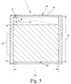
- FIG. 5 shows a schematic diagram of an optical monitoring system with only one Camera 2.
- Camera 2 is located in the upper left corner of door area 1 of the elevator. Due to the large opening angle 22 of the lens of the camera 2 The entire area to be monitored can have a width of about 100 ° 2.50 m and a height 25 of 2.00 m can be detected.
- the door area 1 is not too large, safe monitoring of door area 1 with only one Camera 2 possible, which reduces the cost of the optical surveillance system can be.
Landscapes
- Physics & Mathematics (AREA)
- General Physics & Mathematics (AREA)
- Engineering & Computer Science (AREA)
- Computer Vision & Pattern Recognition (AREA)
- Closed-Circuit Television Systems (AREA)
- Burglar Alarm Systems (AREA)
- Indicating And Signalling Devices For Elevators (AREA)
- Holo Graphy (AREA)
Abstract
Description
Die Erfindung betrifft zum einen ein Verfahren zur optischen Überwachung eines Raumbereichs, insbesondere des Türbereichs eines Aufzuges, wobei von dem Raumbereich mit einer Kamera ein digitales Bild erzeugt wird und die Grauwerte des aktuellen Bildes mit den Grauwerten eines Referenzbildes in einer Auswerteeinheit pixelweise verglichen und das Ergebnis ausgewertet wird. Zum anderen betrifft die Erfindung ein optisches Überwachungssystem zur Erfassung eines Raumbereichs, insbesondere des Türbereichs eines Aufzuges, mit mindestens einer digitalen Kamera und einer Auswerteeinheit, wobei die digitale Kamera ein Kameramodul und einen A/D-Wandler und die Auswerteeinheit einen Mikroprozessor und einen Bildspeicher aufweisen und die Auswerteeinheit die Grauwerte eines aktuellen Bildes mit den Grauwerten eines Referenzbildes pixelweise vergleicht und die Differenz zwischen den Grauwerten des aktuellen Bildes und den Grauwerten des Referenzbildes auswertet.The invention relates on the one hand to a method for the optical monitoring of a Room area, in particular the door area of an elevator, with the space area a digital image is generated with a camera and the gray values of the current one Image with the gray values of a reference image in an evaluation unit compared pixel by pixel and the result is evaluated. On the other hand, it concerns Invention an optical monitoring system for detecting a spatial area, in particular the door area of an elevator, with at least one digital camera and an evaluation unit, the digital camera having a camera module and one A / D converter and the evaluation unit a microprocessor and an image memory and the evaluation unit shows the gray values of a current image with the Gray values of a reference image are compared pixel by pixel and the difference between evaluates the gray values of the current image and the gray values of the reference image.
Zur Überwachung des Türbereichs von Aufzügen, werden seit mehr als einem Jahrzehnt Lichtschranken verwendet, wobei auf der einen Öffnungsseite des Aufzuges die Sender und auf der anderen Öffnungsseite die Empfänger angeordnet sind. Ein solches Verfahren zur Überwachung eines Raumbereichs ist beispielsweise aus der deutschen Patentschrift 36 20 227 bekannt. Dabei sollen die Lichtschranken die Anwesenheit einer Person oder eines Gegenstandes im überwachten Raumbereich dadurch detektieren, daß der Lichtstrahl zwischen Sender und Empfänger durch die Person oder den Gegenstand unterbrochen wird. Hierbei treten zumindest zwei Schwierigkeiten auf: Zum einen muß sichergestellt werden, daß der Lichtstrahl die Person oder den Gegenstand, wenn er sich im überwachten Raumbereich befindet, erfaßt, zum anderen muß dann, wenn sich keine Person oder kein Gegenstand im überwachten Raumbereich befindet, der Lichtstrahl, der von dem Sender ausgestrahlt wird, auf den Empfänger treffen. Hierzu ist eine genaue Justage von Sender und Empfänger notwendig. Das erste Problem kann zwar durch eine Erhöhung der Anzahl der Lichtschranken reduziert werden, damit erhöht sich aber automatisch der Aufwand zur Justage der nun zahlreicheren Sender und Empfänger.Monitoring the door area of elevators has been around for more than a decade Light barriers are used, being on one opening side of the elevator the transmitters and the receivers are arranged on the other opening side. On Such a method for monitoring a room area is known, for example, from US Pat German patent 36 20 227 known. The light barriers should ensure the presence a person or an object in the monitored area detect that the light beam between transmitter and receiver through the Person or object is interrupted. Here at least two occur Difficulties: On the one hand it must be ensured that the light beam Detects person or object when it is in the monitored area, on the other hand, if no person or object is under surveillance Area, the light beam emitted by the transmitter will meet the recipient. This is an exact adjustment of the transmitter and Receiver necessary. The first problem can be increased by increasing the number of the light barriers are reduced, but this automatically increases the Adjustment of the now more numerous transmitters and receivers.
Insbesondere bei Lastenaufzügen besteht die Notwendigkeit, eine Vielzahl von Lichtschranken vorzusehen, da nicht nur geschlossene Gegenstände transportiert werden sollen, sondern auch große und weitgehend offene Gegenstände. Bei weitgehend offenen Gegenständen besteht beim Vorhandensein nur einer einzigen Lichtschranke die Gefahr, daß der vom Sender ausgehende Lichtstrahl den offenen Bereich eines Gegenstandes trifft, also durch diesen hindurchgeht und somit die Lichtschranke nicht "erkennt", daß sich ein Gegenstand im Überwachungsbereich befindet. Gerade bei Lastenaufzügen jedoch, wo eine größere Anzahl von Lichtschranken häufig erforderlich ist, ist die Gefahr relativ groß, daß die Sender und Empfänger, welche sich seitlich in dem Türbereich befinden, durch große und schwere Gegenstände beschädigt werden. Verschiedene bekannte Ausführungsformen von Aufnahmeelementen für die Sender und Empfänger verringern zwar die Wahrscheinlichkeit, daß diese direkt beschädigt werden, dennoch kann es durch mögliche Stöße zu einer Fehljustage zwischen Sender und Empfänger kommen.In the case of freight elevators in particular, there is a need for a large number of Provide light barriers, since not only closed objects are transported but also large and largely open objects. At largely open objects exist when there is only a single light barrier the danger that the light beam emanating from the transmitter will cover the open area hits an object, i.e. passes through it and thus the light barrier does not "recognize" that an object is in the surveillance area. However, especially with freight lifts, where a larger number of light barriers is often required, the risk is relatively high that the transmitter and receiver, which are located on the side of the door area due to large and heavy objects to be damaged. Various known embodiments of receiving elements for the sender and receiver reduce the probability that these can be damaged directly, but possible shocks can lead to a There is a misalignment between the transmitter and receiver.
Wird die Anzahl der Sender und Empfänger erhöht, um auch kleinere Gegenstände erfassen zu können, so erhöht sich damit die Gefahr von Fehlinformationen, da durch die Streuung der Lichtstrahlen auf einen Empfänger treffen können, der nicht zum Empfang dieser Lichtstrahlen bestimmt ist. Um die Gefahr solcher Fehlinformationen zu verhindern, sind aufwendige Steuerungen für die Sender und die Empfänger nötig, die dafür sorgen, daß ein Empfänger nur dann empfangsbereit ist, wenn der ihm zugeordnete Sender einen Lichtstrahl ausgesandt hat.The number of transmitters and receivers is increased to include smaller items To be able to record, increases the risk of misinformation because the scattering of the light rays can hit a receiver that is not intended to receive these light rays. To the danger of such misinformation Prevent complex controls for the transmitter and the Recipients necessary to ensure that a recipient is only ready to receive when the transmitter assigned to it has emitted a light beam.
Die zuvor genannten Probleme können durch die Verwendung des eingangs beschriebenen optischen Überwachungssystem mit einer digitalen Kamera gelöst werden. Ein derartiges Überwachungssystem ist aus der deutschen Offenlegungsschrift 195 25 875 bekannt. Es wird zur Überwachung eines sicherheitsrelevanten Bereiches vor einer automatischen Tür oder einer Durchgangsschleuse mit einem Zugangskontrollsystem verwendet. Durch das aus der deutschen Offenlegungsschrift 195 25 875 bekannte Überwachungssystem wird die Anwesenheit von Personen in dem relevanten Bereich detektiert, so daß als Überwachungsfeld der bodennahe Bereich von einer CCD-Kamera aufgenommen wird. Da derartige optischen Überwachungssysteme mit einer digitalen Kamera relativ teuer sind, werden sie in der Regel nur dort eingesetzt, wo eine hohe Anforderung an die Sicherheit gestellt wird.The aforementioned problems can be solved by using the above optical surveillance system can be solved with a digital camera. Such a monitoring system is from the German published application 195 25 875 known. It is used to monitor a safety-relevant area in front of an automatic door or a passage gate with an access control system used. By that from the German published application 195 25 875 known surveillance system is the presence of people in the relevant area is detected, so that the area close to the ground is used as the monitoring field is recorded by a CCD camera. Because such optical surveillance systems With a digital camera they are usually expensive only used where there is a high security requirement.
Aufgabe der vorliegenden Erfindung ist es nun, ein Verfahren zur optischen Überwachung eines Raumbereichs bzw. ein optisches Überwachungssystem zur Verfügung zu stellen, mit dem zum einen ein sicheres Erfassen von auch sehr kleinen Gegenständen in dem Raumbereich möglich ist, das zum anderen äußerst zuverlässig und fehlersicher arbeitet.The object of the present invention is now a method for optical monitoring a room area or an optical monitoring system with which, on the one hand, a reliable detection of even very small objects is possible in the room area, which is extremely reliable and fail-safe is working.
Diese Aufgabe wird bei dem eingangs genannten Verfahren zunächst und im wesentlichen dadurch gelöst, daß die Auswerteeinheit die Funktionsfähigkeit der Kamera überwacht, insbesondere das Vorhandensein eines Synchronsignals der Kamera und/oder das Unter- und/oder Überschreiten einer Grundhelligkeit des aktuellen Bildes und/oder das Unterschreiten einer vorgegebenen Helligkeitsstreuung überprüft. Die Auswerteeinheit, welche einen Mikroprozessor aufweist, hat somit nicht nur die Aufgabe, die eigentliche Auswertung und Verarbeitung der von der Kamera gelieferten Informationen durchzuführen, sondern sie überprüft gleichzeitig auch die Funktionsfähigkeit der Kamera. Die Überwachung kann dabei sowohl während des aktiven Betriebes der Kamera als auch in Stillstandszeiten der Kamera bzw. des Aufzuges erfolgen. Ein Ausfall der Kamera kann auf einfache Art durch zyklisches Testen eines Synchronsignals festgestellt werden. Durch das Überwachen der Grundhelligkeit des aktuellen Bildes kann sowohl ein Beleuchtungsausfall - Unterschreiten der Grundhelligkeit - als auch ein externes Blenden der Kamera durch Fremdlicht - Überschreiten der Grundhelligkeit - festgestellt werden. Auch bei homogener Lichtverteilung entsteht eine gewisse Helligkeitsstreuung des aktuellen Bildes durch die Textur des Bildhintergrundes. Dies wird bei der Überprüfung der Helligkeitsstreuung berücksichtigt. Unterschreitet die Helligkeitsstreuung einen vorgegebenen Wert, so deutet dies auf einen Kameraschaden hin, beispielsweise den Ausfall eines Kamerachips, der durch die alleinige Überprüfung des Synchronsignales nicht notwendigerweise festgestellt werden kann.This task is first and foremost in the above-mentioned method solved in that the evaluation unit the functionality of the camera monitors, in particular the presence of a synchronous signal from the camera and / or falling below and / or exceeding a basic brightness of the current image and / or the undershoot of a predetermined brightness scatter is checked. The evaluation unit, which has a microprocessor, does not only have the Task, the actual evaluation and processing of those supplied by the camera Carry out information, but at the same time it also checks the functionality the camera. Monitoring can take place both during the active Operation of the camera as well as during downtimes of the camera or the elevator. A failure of the camera can be easily done by cyclically testing one Synchronous signal can be determined. By monitoring the basic brightness of the current image can be both a lighting failure - falling below the basic brightness - as well as external glare to the camera due to extraneous light - exceeding the basic brightness - can be determined. Even with homogeneous light distribution there is a certain spread of brightness in the current image due to the texture of the Image background. This is taken into account when checking the brightness scatter. If the brightness scatter falls below a predetermined value, indicates this is due to camera damage, for example the failure of a camera chip that not necessarily determined by checking the synchronous signal alone can be.
Die Sicherheit der optischen Überwachung kann vorteilhafterweise dadurch weiter erhöht werden, daß ein Überwachungsprozessor zur Überprüfung der Auswerteeinheit zyklisch Prüfsignale an die Auswerteeinheit sendet und umgekehrt die Auswerteeinheit zur Überprüfung des Überwachungsprozessors ebenfalls Prüfsignale an den Überwachungsprozessor sendet. Sendet der Überwachungsprozessor ein Prüfsignal an die Auswerteeinheit, so muß diese das Prüfsignal innerhalb einer definierten Zeitspanne quittieren. Erhält der Überwachungsprozessor diese Quittierung nicht, so bedeutet dies, daß die Auswerteeinheit einen Fehler aufweist. Entsprechend funktioniert auch die Kontrolle des Überwachungsprozessors von der Auswerteeinheit aus.The security of the optical monitoring can thereby advantageously further be increased that a monitoring processor to check the evaluation unit cyclically sends test signals to the evaluation unit and vice versa the evaluation unit to check the monitoring processor also test signals to the Monitoring processor sends. The monitoring processor sends a test signal to the evaluation unit, it must send the test signal within a defined period of time Acknowledge. If the monitoring processor does not receive this acknowledgment, it means this means that the evaluation unit has an error. Works accordingly also control of the monitoring processor from the evaluation unit.
Eine weitere vorteilhafte Verbesserung erfährt das erfindungsgemäße Verfahren dadurch, daß der Überwachungsprozessor auf Anweisung der Auswerteeinheit periodisch Testbilder an einen Eingang sendet, insbesondere an einen Videomultiplexeingang der Kamera. Die Aussendung des Testbildes von dem Überwachungsprozessor an einen Eingang der Kamera wird von der Auswerteeinheit quittiert, so daß diese die Verarbeitung des Testbildes in der digitalen Kamera überprüft. Hat die Überprüfung des Testbildes durch die Auswerteeinheit ein fehlerfreies Arbeiten der digitalen Kamera ergeben, so wird die von dem Überwachungsprozessor gesetzte Quittierung zurückgenommen. Andernfalls liefert die Auswerteeinheit ein Fehlersignal. Dieser Überwachungsprozeß ist somit ein dynamischer Prozeß; bleibt der Prozeß stationär, so ist ein Fehler erkennbar.The method according to the invention is further improved by that the monitoring processor periodically at the instruction of the evaluation unit Sends test images to an input, in particular to a video multiplex input the camera. The transmission of the test image from the monitoring processor at an input of the camera is acknowledged by the evaluation unit, so that this checked the processing of the test image in the digital camera. Has the review of the test image by the evaluation unit, error-free working of the digital Camera, the acknowledgment set by the monitoring processor withdrawn. Otherwise the evaluation unit delivers an error signal. This Monitoring process is thus a dynamic process; the process remains stationary, so an error is recognizable.
Vorzugsweise wird der zu überwachende Raumbereich durch eine Beleuchtungseinrichtung ausgeleuchtet. Durch diese Beleuchtungseinrichtung ist sichergestellt, daß immer ausreichend Licht für die Aufnahme der Bilder zur Verfügung steht, so daß die Überwachung unabhängig von den im Einsatz sehr unterschiedlichen Lichtverhältnissen stattfinden kann. Arbeitet die Beleuchtungseinrichtung mit Licht aus dem sichtbaren Wellenlängenbereich, so ist der überwachte Raumbereich für den Benutzer erkennbar. Das Licht kann dann mittels Stablinsen gebündelt und als breite Linie auf dem Boden des Überwachungsbereichs projektiert werden. Arbeitet die Beleuchtungseinrichtung dagegen mit Licht aus dem infraroten Bereich, so kann verhindert werden, daß durch Streulicht aus der Umgebung Fehlinformationen entstehen. Vorteilhafterweise arbeitet die Beleuchtungseinrichtung im Pulsbetrieb, wodurch eine wesentlich höhere Lichtleistung möglich ist als im Dauerbetrieb.The area to be monitored is preferably provided by an illumination device illuminated. This lighting device ensures that there is always sufficient light available for taking the pictures, so that the Monitoring regardless of the very different lighting conditions in use can take place. The lighting device works with light from the visible wavelength range, this is the monitored area for the user recognizable. The light can then be focused using rod lenses and as a wide line be configured on the floor of the monitoring area. The lighting device works on the other hand, with light from the infrared range, can be prevented be that misinformation is created by scattered light from the environment. advantageously, the lighting device works in pulsed mode, thereby a much higher light output is possible than in continuous operation.
Nach einer weiteren, besonders vorteilhaften Ausgestaltung der Erfindung, die hier noch beschrieben werden soll, schaltet die Auswerteeinheit periodisch eine Leuchtdiode ein, wodurch die Kamera geblendet wird. Die Auswerteeinheit vergleicht daraufhin das von der Kamera aufgenommene Bildmuster mit einem in einem Bildspeicher gespeicherten vorgegebenen Bildmuster. Hierdurch kann mit einem einzigen Test die gesamte digitale Kamera auf Fehler überprüft werden, d. h. sowohl die eigentliche Kameraoptik, das die Bildanpassung durchführende Kameramodul mit der Kameraelektronik und der A/D-Wandler. Zusätzlich wird auch noch der Bildspeicher überprüft, welcher der Auswerteeinheit dazugerechnet ist. Auch wenn nur in einem dieser Bauteile ein Fehler auftritt, so wird dies durch dieses Testverfahren festgestellt.According to a further, particularly advantageous embodiment of the invention, which is here to be described, the evaluation unit periodically switches a light emitting diode which blinds the camera. The evaluation unit then makes a comparison the image pattern recorded by the camera with one in an image memory stored preset image pattern. This can be done with a single Test the entire digital camera for errors, d. H. both the actual Camera optics that perform the image adjustment with the camera module Camera electronics and the A / D converter. In addition, the image memory is also checks which of the evaluation units is included. Even if only in one If these components fail, this is determined by this test procedure.
Um eine optimale Sicherheit auch im Falle eines Feuers im Inneren des Aufzuges zu gewährleisten, ist das Ausgangssignal der Auswerteeinheit innerhalb der Steuerung des Aufzuges einem Feueralarm logisch untergeordnet. Dadurch ist sichergestellt, daß im Falle eines Feuers der Aufzug auf jeden Fall bis zur nächsten Etage fährt, unabhängig vom Signal der Auswerteeinheit. Dabei kann der Feueralarm beispielsweise von einem Rauchmelder im Inneren des Aufzuges kommen oder auch extern ausgelöst worden sein. Wäre das "Alarm"-Signal der Auswerteeinheit logisch allen anderen Steuerungsbefehlen des Aufzuges übergeordnet, so könnte dies dazu führen, daß bei einem Feuerausbruch der Aufzug automatisch stoppen würde, auch wenn er sich zwischen zwei Etagen befinden würde. Dies wäre besonders bei Personenaufzügen, aber auch bei Lastenaufzügen, ein zu großes Gefahrenrisiko.To ensure optimal safety even in the event of a fire inside the elevator ensure, is the output signal of the evaluation unit within the control of the elevator logically subordinate to a fire alarm. This ensures that in the event of a fire, the elevator definitely goes to the next floor, regardless from the signal of the evaluation unit. The fire alarm can, for example come from a smoke detector inside the elevator or triggered externally have been. Would the "alarm" signal of the evaluation unit be logical to all others Superordinate control commands of the elevator, this could lead to that at In the event of a fire, the elevator would stop automatically, even if it did would be located between two floors. This would be especially the case with passenger lifts, but also with freight lifts, too great a risk.
Nach einer letzten, hier noch zu beschreibenden vorteilhaften Ausgestaltung des erfindungsgemäßen Verfahrens zur Überwachung des Türbereichs eines Aufzuges löst der Prozessor der Aufzugssteuerung zyklische Tests zur Überprüfung der Kommunikation zwischen der Aufzugssteuerung und der Auswerteeinheit aus. Bei fehlerfreier Kommunikation zwischen der Auswerteeinheit und der Aufzugssteuerung antwortet die Auswerteeinheit bei einer solchen Testauslösung mit einer Invertierung aller Überwachungsausgänge zur Aufzugssteuerung, welche beim Zurücknehmen der Testauslösung wieder in Normalstellung umgeschaltet werden. Somit wird auch ein Drahtbruch als möglich Fehlerquelle durch das Verfahren selbständig überprüft.According to a last advantageous embodiment of the invention according to the invention, which will be described here Method for monitoring the door area of an elevator triggers the processor of the elevator control cyclical tests to check the communication between the elevator control and the evaluation unit. With error-free Communication between the evaluation unit and the elevator control responds the evaluation unit with such a test triggering with an inversion of all Monitoring outputs for elevator control, which when the Test triggering can be switched back to normal position. Thus also a Broken wire as possible Source of error checked by the process independently.
Bei dem eingangs beschriebenen optischen Überwachungssystem ist die der Erfindung zugrundeliegende Aufgabe dadurch gelöst, daß der Mikroprozessor die Funktionstüchtigkeit der digitalen Kamera überwacht, insbesondere das Vorhandensein eines Synchronsignals der Kamera und/oder das Unter- und/oder Überschreiten der Grundhelligkeit des aktuellen Bildes und/oder das Unterschreiten einer vorgegebenen Helligkeitsstreuung überprüft. In the case of the optical monitoring system described at the outset, that of the invention underlying task solved in that the microprocessor is functional monitors the digital camera, especially the presence a synchronous signal from the camera and / or falling below and / or exceeding the Basic brightness of the current image and / or falling below a predetermined Brightness scatter checked.
Bei einer bevorzugten Ausführungsform des erfindungsgemäßen optischen Überwachungssystems gilt, daß das Überwachungssystem einerseits ein Service-Interface zum Anschluß einer Parametriereinrichtung, beispielsweise eines Computers, aufweist und andererseits an die Steuerung des Aufzuges angeschlossen ist. Durch die Parametriereinrichtung kann das optische Überwachungssystem vor Ort optimal an die gegebenen Anforderungen und Einsatzbedingungen angepaßt werden. So kann genau der Bildausschnitt ausgewählt werden, der überwacht werden soll, was beispielsweise durch die Einstellung des richtigen Öffnungswinkels der Kamera geschieht. Ebenso kann der Schwellwert festgelegt werden, ab dem die Differenz zwischen dem Pixel des aktuellen Bildes und dem Pixel des Referenzbildes als Änderung erkannt und damit als Fehler gezählt werden. Weiter kann die Anzahl der zulässigen Fehler eingestellt werden, ab der das Überwachungssystem ein "Alarm"-Signal erzeugt.In a preferred embodiment of the optical monitoring system according to the invention applies that the monitoring system is a service interface for connecting a parameterization device, for example a computer and on the other hand is connected to the control of the elevator. Through the parameterization device can the optical surveillance system on site optimally match the given requirements and conditions of use. So exactly the image section that is to be monitored, for example what is selected happens by setting the correct opening angle of the camera. The threshold value from which the difference between the pixel of the current image and the pixel of the reference image as a change recognized and thus counted as errors. Furthermore, the number of allowed Errors are set from which the monitoring system generates an "alarm" signal.
Vorzugsweise ist eine infrarotes Licht aussendende Beleuchtungseinrichtung vorgesehen und sind die Kameras mit einem Infrarot-Bandpaßfilter ausgestattet. Als Beleuchtungseinrichtung kann dabei ein Leuchtdiodenarray verwendet werden. Durch das Infrarot-Bandpaßfilter wird verhindert, daß durch Streulicht aus der Umgebung Fehlinformationen entstehen können.An illuminating device emitting infrared light is preferably provided and the cameras are equipped with an infrared bandpass filter. As a lighting device an LED array can be used. By The infrared bandpass filter is prevented from stray light from the environment Misinformation can arise.
Im einzelnen gibt es nun eine Vielzahl von Möglichkeiten, das erfindungsgemäße Verfahren zur optischen Überwachung bzw. das erfindungsgemäße optische Überwachungssystem auszugestalten und weiterzubilden. Dazu wird verwiesen einerseits auf die den Patentansprüchen 1 und 8 nachgeordneten Patentansprüche, andererseits auf die Beschreibung bevorzugter Ausführungsbeispiele in Verbindung mit der Zeichnung. In der Zeichnung zeigen
- Fig. 1
- ein Blockdiagramm zur Erläuterung der Bildauswertung in der Auswerteeinheit eines erfindungsgemäßen Überwachungssystems,
- Fig. 2
- ein Blockschaubild eines erfindungsgemäßen optischen Überwachungssystems,
- Fig. 3
- eine Prinzipskizze eines ersten Ausführungsbeispiels eines optischen Überwachungssystems,
- Fig. 4
- eine Prinzipskizze eines zweiten Ausführungsbeispieles eines optischen Überwachungssystems und
- Fig. 5
- eine Prinzipskizze eines Ausführungsbeispiels eines optischen Überwachungssystems mit nur einer Kamera.
- Fig. 1
- 2 shows a block diagram to explain the image evaluation in the evaluation unit of a monitoring system according to the invention,
- Fig. 2
- 2 shows a block diagram of an optical monitoring system according to the invention,
- Fig. 3
- 1 shows a schematic diagram of a first exemplary embodiment of an optical monitoring system,
- Fig. 4
- a schematic diagram of a second embodiment of an optical monitoring system and
- Fig. 5
- a schematic diagram of an embodiment of an optical monitoring system with only one camera.
Anhand von Fig. 1 soll die grundsätzliche Verfahrensweise der Bildauswertung mit der Auswerteeinheit eines erfindungsgemäßen Überwachungssystems erläutert werden:With reference to Fig. 1, the basic procedure of the image evaluation with the evaluation unit of a monitoring system according to the invention are explained:
Zunächst wird ein Referenzbild des zu überwachenden Raumbereichs gemacht und in einem Bildspeicher zwischengespeichert. Anschließend wird das aktuelle Bild erstellt und ebenfalls zwischengespeichert. Die in dem Blockdiagramm mit n bezeichnete Zählvariable für die Pixel ist zu Beginn auf "0" gesetzt. Sind beide Bilder gespeichert, so wird n um "1" erhöht und somit das erste Pixel des Referenzbildes und das entsprechende erste Pixel des aktuellen Bildes in der Auswerteeinheit miteinander verglichen. Hierzu werden die Grauwerte der beiden Pixel voneinander subtrahiert und der Absolutbetrag der Differenz gebildet. Ist der Absolutbetrag größer als ein vorher eingegebener Schwellwert, so wird dies als Fehler gewertet. Die Anzahl m der Fehler, welche zu Beginn des Vergleichs "0" beträgt, wird um "1" erhöht. Ist die Anzahl m der Fehler größer als ein vorher eingestellter Grenzwert X, so erzeugt die Auswerteeinheit als Ausgangssignal ein "Alarm"-Signal. Ist die Anzahl m der Fehler kleiner als der Grenzwert X, so wird verglichen, ob die Anzahl n der bisher untersuchten Pixel gleich der Anzahl E aller vorhandenen Pixel ist. Ist n gleich E, d. h. es sind alle Pixel des aktuellen Bildes und des Referenzbildes miteinander verglichen worden, so erzeugt die Auswerteeinheit als Ausgangssignal ein "ok"-Signal. Wenn bei dem Vergleich der beiden Grauwerte der Absolutbetrag der Differenz kleiner als der Schwellwert ist, wird überprüft, ob die Anzahl n der untersuchten Pixel gleich der Anzahl E aller vorhandenen Pixel ist. Ist dies der Fall, so wird auch hier ein "ok"-Signal ausgegeben. Ist die Anzahl n der untersuchten Pixel jedoch kleiner als die Anzahl E aller vorhandenen Pixel, so wird n um "1" erhöht und es werden das nächste Pixel des Referenzbildes und des aktuellen Bildes miteinander verglichen.First, a reference picture of the area to be monitored is made and temporarily stored in an image memory. The current image is then created and also cached. The one labeled n in the block diagram Count variable for the pixels is initially set to "0". If both pictures are saved, so n is increased by "1" and thus the first pixel of the reference image and the corresponding first pixels of the current image in the evaluation unit with one another compared. For this purpose, the gray values of the two pixels are subtracted from one another and the absolute amount of the difference is formed. If the absolute amount is greater than one previously entered threshold value, this is considered an error. The number m of Errors which are "0" at the beginning of the comparison are increased by "1". Is the number If the error is greater than a previously set limit value X, the evaluation unit generates an "alarm" signal as the output signal. If the number m of errors is smaller than the limit value X, it is compared whether the number n of those examined so far Pixel is equal to the number E of all available pixels. If n is E, i. H. they are all Pixels of the current image and the reference image have been compared with one another, see above the evaluation unit generates an "ok" signal as the output signal. If in the comparison of the two gray values, the absolute amount of the difference is smaller than the threshold value it is checked whether the number n of the examined pixels is equal to the number E of all existing pixels. If this is the case, an "ok" signal is also output here. However, the number n of pixels examined is smaller than the number E of all existing pixels, n is increased by "1" and it becomes the next pixel of the reference image and the current image compared.
Das zuvor beschriebene Auswerten wiederholt sich so oft, bis entweder die Anzahl m der Fehler größer als der Grenzwert X ist oder bis die Anzahl n der untersuchten Pixel gleich der Anzahl E aller vorhandenen Pixel ist. Ein solcher pixelweiser Vergleich von Referenzbild und aktuellem Bild dauert dabei lediglich ca. 250 ms, so daß durch ein von der Auswerteeinheit erzeugtes "Alarm"-Signal über ein Steuerimpuls an die Steuerung des Aufzuges innerhalb von Sekundenbruchteilen ein Schließen der Tür des Aufzuges verhindert wird.The evaluation described above is repeated until either the number m the error is greater than the limit value X or until the number n of the examined pixels is equal to the number E of all available pixels. Such a pixel-by-pixel comparison of The reference image and the current image only take about 250 ms, so that by a "Alarm" signal generated by the evaluation unit via a control pulse to the Control of the elevator within a fraction of a second closing the door the elevator is prevented.
Durch Verändern des Schwellwertes für die Fehlerentscheidung und/oder des Grenzwertes für die Signalentscheidung kann eine den jeweiligen Erfordernissen angepaßte Einstellung der Empfindlichkeit vorgenommen werden.By changing the threshold value for the error decision and / or the limit value for the signal decision one can be adapted to the respective requirements Adjustment of the sensitivity can be made.
Nach einer besonders vorteilhaften Ausgestaltung des erfindungsgemäßen Verfahrens wird nach einer bestimmten Anzahl von aufeinanderfolgenden störungsfreien Auswertungen, d. h. wenn die Auswerteeinheit eine bestimmten Anzahl von aufeinanderfolgenden "ok"-Signalen ausgegeben hat, ein neues Referenzbild erzeugt und gespeichert. Im Lauf der Zeit kann es dazu kommen, daß das von einem "leeren" Raumbereich erzeugte aktuelle Bild nicht mehr mit dem ursprünglich gespeicherten Referenzbild übereinstimmt, so daß sich mit der Zeit die Anzahl der als Fehler erkannten Pixel erhöhen und zu einem "Alarm"-Signal führen würde. Dadurch, daß nach einer bestimmten Zeit für den "leeren" Raumbereich ein neues Referenzbild erzeugt wird, wird ein solches fehlerhaftes "Alarm"-Signal verhindert.According to a particularly advantageous embodiment of the method according to the invention after a certain number of consecutive trouble-free Evaluations, d. H. if the evaluation unit a certain number of successive "ok" signals, generated a new reference image and saved. Over time, this can happen from an "empty" Space area no longer creates current image with the originally saved one Reference image coincides, so that over time the number of errors recognized Pixels would increase and lead to an "alarm" signal. The fact that after a certain time for the "empty" area creates a new reference image such an erroneous "alarm" signal is prevented.
Fig. 2 zeigt ein Blockschaubild eines erfindungsgemäßen optischen Überwachungssystems
mit einer digitalen Kamera 2 und einer Auswerteeinheit 3. Die digitale Kamera
2 besteht zunächst aus einer Kameraoptik 4, welche an ein - zumindest zwei
Eingänge E 1 und E 2 aufweisendes - Kameramodul 5 angeschlossen ist, und aus einem
A/D-Wandler 6. Der Eingang E 2 des Kameramoduls 5 ist als Videomultiplexer-Eingang
ausgebildet. Die digitale Kamera 2 weist einen CCD-Chip mit einer Größe
von beispielsweise 530 x 590 Bildpunkten auf. An das Kameramodul 5 können unterschiedliche
Kameraoptiken 4 mit unterschiedlichen Öffnungswinkeln zwischen
beispielsweise 30° und 70° angeschlossen werden.2 shows a block diagram of an optical monitoring system according to the invention
with a
Die Auswerteeinheit 3 besteht zumindest aus einem Mikroprozessor 7, beispielsweise
einem 16 Bit Mikroprozessor vom Typ MC 68332, und aus einem Bildspeicher 8. Der
Bildspeicher 8 erhält von dem A/D-Wandler 6 die von der Kamera 2 aufgenommenen
Bilder. Zu der Auswerteeinheit 3 gehören darüber hinaus noch mehrere Speicher 9
bis 11, in denen einerseits die Programmdaten für das Überwachungsprogramm abgelegt
sind, Speicher 9, die andererseits die Konfigurationsdaten, zum Beispiel Überwachungsfensterbereich,
Helligkeitsgrenze etc. enthalten. Diese Konfigurationsdaten
sind jeweils in den Speichern 10 und 11 abgelegt, so daß ein laufender Vergleich der
Konfigurationsdaten möglich ist.The
Da sowohl die digitale Kamera 2 - mit Ausnahme der Kameraoptik 4 - als auch die
Auswerteeinheit 3 hardwaremäßig auf einer Platine angeordnet sind, ist eine genau
Unterteilung und Zuordnung der einzelnen Bauteile schwer möglich. Insbesondere
könnte der Bildspeicher 8 anstatt der Auswerteeinheit 3 auch der digitalen Kamera 2
zugerechnet werden, was für die Funktion des optischen Überwachungssystems insgesamt
keinerlei Unterschied macht.Since both the digital camera 2 - with the exception of the camera optics 4 - and the
Erfindungsgemäß überwacht nun die Auswerteeinheit 3 und hierbei insbesondere der
Mikroprozessor 7 die Funktionstüchtigkeit der digitalen Kamera 2, in dem das Vorhandensein
eines Synchronsignals der Kamera 2 und/oder das Unter- und/oder Überschreiten
einer Grundhelligkeit des aktuellen Bildes und/oder das Unterschreiten einer
vorgegebenen Helligkeitsstreuung überprüft wird. Dadurch wird nicht nur ein
Totalausfall der Kamera 2 erfaßt, sondern durch die Überwachung der Grundhelligkeit
auch ein Beleuchtungsausfall einerseits und ein Blenden der Kameraoptik 4
durch Fremdlicht andererseits festgestellt. Schließlich kann durch die Überwachung
der Helligkeitsstreuung auch ein Defekt in dem Kameramodul 5 festgestellt werden.
Sowohl die Fehlergrenze für die Grundhelligkeit als auch für die Helligkeitsstreuung
können bei Inbetreibnahme der Überwachungseinrichtung eingestellt und gegebenenfalls
auch später an veränderte Bedingungen angepaßt werden. According to the invention, the
Zu dem durch das Blockschaubild in Fig. 2 dargestellten optischen Überwachungssystem
gehört auch noch ein Überwachungsprozessor 12, welcher beispielsweise mit
einem Mikrokontroller des Typs PIC 16 C 54 realisiert werden kann. Der Überwachungsprozessor
12 ist einerseits mit der Auswerteeinheit 3 und andererseits mit dem
Eingang E 2 des Kameramoduls 5 verbunden. Durch die bidirektionale Verbindung
zwischen dem Überwachungsprozessor 12 und der Auswerteeinheit 3 kann sowohl
der Überwachungsprozessor 12 die Auswerteeinheit 3 überprüfen als auch umgekehrt
die Auswerteeinheit 3 den Überwachungsprozessor 12. Hierzu übergibt beispielsweise
der Überwachungsprozessor 12 ein Prüfsignal an die Auswerteeinheit 3,
welches innerhalb einer definierten Zeitspanne von der Auswerteeinheit 3 quittiert
werden muß. Die Zykluszeit für eine solche Überprüfung beträgt dabei in der Regel
weniger als 200 ms. Darüber hinaus kann mit Hilfe des Überwachungsprozessors 12
auch die digitale Kamera 2, hierbei insbesondere der A/D-Wandler 6 sowie der Bildspeicher
8, überprüft werden. Hierfür sendet der Mikroprozessor 7 eine Anforderung
zur Aussendung eines Testbildes an den Überwachungsprozessor 12. Diese Anforderung
wird dem Mikroprozessor 7 von dem Überwachungsprozessor 12 quittiert, der
daraufhin ein Testbild an den Videomultiplexer-Eingang E 2 des Kameramoduls 5
schickt. Der Mikroprozessor 7 überwacht das von dem A/D-Wandler 6 digitalisierte
und in dem Bildspeicher 8 gespeicherte Testbild und wertet eventuelle Abweichungen
zu einem vorgegebenen Bildmuster aus. Hat die Umwandlung und Speicherung
des Testbildes fehlerfrei funktioniert, so nimmt der Mikroprozessor 7 seine an den
Überwachungsprozessor 12 gesendete Anforderung zurück, worauf der Überwachungsprozessor
12 seine Quittierung ebenfalls zurücknimmt. Dieser Vorgang ist somit
dynamisch; bleibt der Prozeß stationär, das heißt, nimmt der Mikroprozessor 7
und/oder der Überwachungsprozessor 12 seine Anforderung bzw. seine Quittierung
nicht zurück, so erfolgt eine Fehlermeldung.Regarding the optical monitoring system represented by the block diagram in FIG. 2
also includes a
Fig. 2 zeigt darüber hinaus noch ein Service-Interface 13 zum Anschluß einer Parametrieeinrichtung, beispielsweise eines Computers, eines Labtops oder auch eines Bildschirms zur Überprüfung und Darstellung der eingegebenen Werte. Ein Ein/Ausgabemodul 14 und ein Relaisausgangsmodul 15 dienen zur Kommunikation mit der hier nicht dargestellten Aufzugssteuerung. Das Ein-/Ausgangsmodul 14 hat zwei Eingänge, zum Einschalten der Überwachung und zum Auslösen eines Testvorganges, und vier Ausgänge, die mit dem Relaisausgangsmodul 15 verbunden sind. Die Relaisausgänge können dabei die folgenden Zustände anzeigen:
- Kamera läuft
- Bereich OK
- Bereich NICHT OK
- Beleuchtung OK
- Camera is running
- OK area
- Area NOT OK
- Lighting OK
Als Kamerabeleuchtung ist eine Beleuchtungseinrichtung 16 vorgesehen, die mehrere
infrarotes Licht aussendende Leuchtdioden 17 aufweist. Die Leuchtdioden 17 werden
mit hoher Leistung bei einer Bildaufnahme gepulst. Eine derartige Beleuchtungseinrichtung
16 kann insbesondere bei schlechten oder stark wechselnden
Lichtverhältnissen vorteilhaft sein. Durch die Verwendung von infrarotem Licht kann
in Verbindung mit einem der Kameraoptik 4 vorgeschalteten Infrarot-Bandpaßfilter
der Einfluß von Streulicht unterdrückt werden.An
Mit einer weiteren besonders lichtstarken Leuchtdiode 18, die von der Auswerteeinheit
3 angesteuert wird, kann die Kamera 2 zu Testzwecken geblendet werden. Wird
die Leuchtdiode 18 von der Auswerteeinheit 3 angesteuert, so kann durch das Blenden
der Kamera 2 der gesamte, für die Aufnahme des Bildes notwendige Zweig des
Überwachungssystems getestet werden. Es wird gleichzeitig die Kameraoptik 4, das
Kameramodul 5, der A/D-Wandler 6 und der Bildspeicher 8 sowie deren Verbindung
untereinander überprüft. Von dem Mikroprozessor 7 wird das von der Kamera 2 aufgenommene
Bild mit einem vorher abgespeicherten Bild verglichen.With another particularly bright light-emitting
Insgesamt können somit alle zu dem optischen Überwachungssystem gehörenden Bauteile durch unterschiedliche Tests auf ihre ordnungsgemäße Funktion überprüft werden. Welche Tests jeweils durchgeführt werden, hängt von dem Überwachungsstatus des optischen Überwachungssystems ab, wobei insbesondere die Wahl zwischen einem hochwertigen Selbsttest bei Stillstand des Aufzuges und einem einfachen Selbsttest bei aktiver Überwachung des Raumbereichs besteht. All in all, all belonging to the optical monitoring system can thus Components are checked for proper function by various tests become. Which tests are performed depends on the monitoring status of the optical monitoring system, in particular the choice between a high-quality self-test when the elevator is at a standstill and a simple one Self-test passed with active monitoring of the room area.
In Fig. 2 sind noch zwei Spannungswandler 19 und eine Spannungsüberwachungseinrichtung
20 dargestellt. Durch die Spannungsüberwachungseinrichtung 20 wird
die Versorgungsspannung in engen Grenzen überprüft und bei Verlassen dieser
Grenzen eine Fehlersignal ausgegeben. Durch die Spannungswandler 19 erfolgt einerseits
eine Umwandlung der Versorgungsspannung von 24 V auf 5 V, andererseits
eine Umwandlung von 5 V auf 9 V als Versorgungsspannung für das Kameramodul 5.In Fig. 2 there are two
Fig. 3 zeigt schematisch den Türbereich 1 eines Aufzuges, bei dem zwei Kameras 2
und zwei Beleuchtungseinrichtungen 16 in der Decke 21 des Aufzuges eingelassen
sind. Die Kameras 2 haben je ein Objektiv mit einem Öffnungswinkel 22 von 70° und
sind in der Mitte der Decke 21 angeordnet. Der Türbereich 1 hat eine Höhe 23 und
eine Breite 24 von jeweils 2,50 m. Der ausgewählte und zu überwachende Raumbereich
1 erfaßt die gesamte Breite 24 des Türbereichs 1, jedoch nur eine Höhe 25 von
2,00 m. Die beiden Kameras 2 sind so ausgerichtet, daß sie den gesamten Raumbereich
erfassen, es auf dem Boden 26 des Türbereichs 1 mittig sogar zu einem kleinen
Überschneidungsbereich 27 kommt. Hierdurch besteht die Möglichkeit, eine Fehlerüberwachung
der Kameras 2 durchzuführen, indem ein Vergleich des Überschneidungsbereichs
27, von dem beide Kameras 2 ein aktuelles Bild machen, durchgeführt
wird. Wenn beide Kameras 2 richtig arbeiten, müssen die jeweiligen Pixel, die von
dem Überschneidungsbereichs 27 gemacht worden sind, bei beiden Kameras 2 übereinstimmen.
Ist dies nicht der Fall, so kann eine Fehlermeldung an eine Kontrollstation
ausgegeben werden.3 schematically shows the
In Fig. 4 ist eine Prinzipskizze eines zweiten Ausführungsbeispiels eines optischen
Überwachungssystems dargestellt. Bei diesem Überwachungssystem werden fünf
Kameras 2 mit je einem Öffnungswinkel 22 von 70° verwendet. Damit wird ein
Raumbereich mit einer Breite 24 von 5,00 m und einer Höhe 25 von 1,73 m vollständig
überwacht. Die Kameras 2 sind mit einem CCD-Sensor mit einer Auflösung von
530 x 590 Pixel ausgestattet. Die Auflösung der Kameras 2, die hier in einer Höhe 28
von 2,50 m an der Decke 21 befestigt sind, beträgt dabei 6,6 mm pro Pixel. Der Abstand
29 der Kameras 2 beträgt 1,07 m und ist zwischen allen Kameras 2 gleich. Dabei
treten mehrere Überschneidungsbereiche 27 auf, durch die eine Fehlerüberwachung
der Kameras 2 möglich ist. Wird ein Punkt 30 von drei oder mehr Kameras 2 überwacht,
so ist nicht nur ein allgemeine Fehlererkennung der Kameras 2 möglich, sondern
es kann sogar ausgewertet werden, welche Kamera 2 fehlerhaft ist. Wenn beispielsweise
für den Punkt 30, der von den drei mittigen Kameras 2 überwacht wird,
zwei Kameras 2 ein übereinstimmendes Pixel gespeichert haben, die dritte Kamera 2
jedoch ein davon abweichendes Pixel, so ist mit großer Wahrscheinlichkeit diese
dritte Kamera 2 defekt.In Fig. 4 is a schematic diagram of a second embodiment of an optical
Monitoring system shown. With this surveillance system, five
Je nach Anwendungsfall können durch die Anzahl der verwendeten Kameras 2,
durch die Wahl des Abstandes 29 zwischen den Kameras 2 und deren Öffnungswinkel
22 unterschiedlich große Raumbereiche mit unterschiedlicher Auflösung überwacht
werden.Depending on the application, the number of cameras used 2,
by the choice of the
Fig. 5 zeigt eine Prinzipskizze eines optischen Überwachungssystems mit nur einer
Kamera 2. Die Kamera 2 befindet sich in der linken oberen Ecke des Türbereichs 1
des Aufzuges. Durch den großen Öffnungswinkel 22 des Objektives der Kamera 2
von etwa 100° kann der gesamte zu überwachende Bereich mit einer Breite 24 von
2,50 m und einer Höhe 25 von 2,00 m erfaßt werden. Bei Aufzügen, deren Türbereich
1 nicht zu groß ist, ist eine sichere Überwachung des Türbereichs 1 mit nur einer
Kamera 2 möglich, wodurch die Kosten des optischen Überwachungssystems reduziert
werden können.5 shows a schematic diagram of an optical monitoring system with only one
Claims (15)
- Method for the optical monitoring of a three-dimensional area, particularly of the door-area of an elevator, wherein a digital picture of said area is generated by a digital camera and the grey values of the current picture are compared with the grey values of a reference picture pixel by pixel in an evaluation unit and evaluating the result, characterized in that the evaluation unit monitors the proper operation of the camera, particularly that the evaluation unit checks the existence of a synchronising signal of the camera and/or that the evaluation unit detects the brightness of the current picture running above or below a certain value and/or the scattering of the brightness running below a certain value.
- Method according to claim 1, characterized in that a monitoring processor cyclically sends test signals to the evaluation unit for testing the evaluation unit and that, inversely, the evaluation unit also sends test signals to the monitoring processor for testing the monitoring processor.
- Method according to claim 2, characterized in that, when triggered by the evaluation unit, the monitoring processor periodically sends test pictures to an input, particularly to a video-multiplexer-input of the camera.
- Method according to any one of the claims 1 to 3, characterized in that the three-dimensional area to be monitored is illuminated by a lighting device, particularly by infrared light-emitting diodes operated in a pulsed mode having high power.
- Method according to any one of the claims 1 to 4, characterized in that when triggered by the evaluation unit, the camera is dazzled by a light-emitting diode and that the evaluation unit compares the corresponding picture pattern taken by the camera with a given picture pattern stored in a picture memory.
- Method according to any one of the claims 1 to 5, characterized in that when the absolute value of the difference between two grey values is higher than a certain threshold value, this is counted as an error and that, dependent on the number of counted errors, the evaluation unit produces a binary signal.
- Method according to any one of the claims 1 to 6, characterized in that, after a number of error-free evaluations, a new reference picture is generated and saved, so that an automatic adaption to changing measuring conditions is achieved.
- Method for monitoring the door-area of an elevator according to any one of the claims 1 to 7, characterized in that, when sensing an object in the door-area of the elevator, a closing of the doors is suppressed, that, in the case of a fire in the elevator, however, the elevator moves to the next floor in every case, regardless of the signal from the evaluation unit.
- Method according to claim 8, characterized in that the elevator control unit cyclically tests the communication with the evaluation unit.
- Optical monitoring system for sensing a three-dimensional area, particularly the door-area (1) of an elevator comprising at least one digital camera (2) and an evaluation unit (3), the digital camera (2) comprising a camera module (5) and an A/D converter (6) and the evaluation unit (3) comprising a microprocessor (7) and a picture memory (8), the evaluation unit (3) comparing the grey values of a current picture with the grey values of a reference picture pixel by pixel and evaluating the difference between the grey values of the current picture and the grey values of the reference picture, characterized in that the microprocessor (7) monitors the proper operation of the digital camera (2), particularly that the microprocessor (7) checks the existence of a synchronising signal of the camera (2) and/or that the microprocessor (7) detects the brightness of the current picture running above or below a certain value and/or the scattering of the brightness running below a certain value.
- Optical monitoring system according to claim 10, characterized in that additionally a monitoring processor (12) is provided and that the monitoring processor (12) monitors the microprocessor (7) and/or that the monitoring processor (12) itself or in combination with the microprocessor (7) monitors the digital camera (2), particularly the A/D converter (6) and the picture memory (8).
- Optical monitoring system according to claim 11, characterized in that the microprocessor (7) tests the monitoring processor (12).
- Optical monitoring system according to any one of the claims 10 to 12, characterized in that the monitoring system has a service-interface (13) for the connection of a parameterising device and, further, that the monitoring system is connected to the elevator control unit.
- Optical monitoring system according to any one of the claims 10 to 13, characterized in that a lighting device (16) emitting infrared light is provided, wherein the lighting device (16) preferably consists of an array of light-emitting diodes and that the camera (2) is provided with an infrared-band-pass filter.
- Method according to any one of the claims 1 to 9, comprising utilising an optical monitoring system according to any one of the claims 10 to 14, characterized in that various cameras (2) monitor one point (30) and that an error control of the cameras (2) is provided by comparison of the pixels corresponding to the monitored point (30) generated by the various cameras (2).
Applications Claiming Priority (4)
| Application Number | Priority Date | Filing Date | Title |
|---|---|---|---|
| DE19740599 | 1997-09-15 | ||
| DE19740599 | 1997-09-15 | ||
| DE19743874 | 1997-10-04 | ||
| DE19743874 | 1997-10-04 |
Publications (3)
| Publication Number | Publication Date |
|---|---|
| EP0902402A2 EP0902402A2 (en) | 1999-03-17 |
| EP0902402A3 EP0902402A3 (en) | 2000-05-17 |
| EP0902402B1 true EP0902402B1 (en) | 2002-07-24 |
Family
ID=26040008
Family Applications (1)
| Application Number | Title | Priority Date | Filing Date |
|---|---|---|---|
| EP98117081A Expired - Lifetime EP0902402B1 (en) | 1997-09-15 | 1998-09-09 | Apparatus and method for optically monitoring a space |
Country Status (3)
| Country | Link |
|---|---|
| EP (1) | EP0902402B1 (en) |
| AT (1) | ATE221232T1 (en) |
| DE (1) | DE59804862D1 (en) |
Cited By (3)
| Publication number | Priority date | Publication date | Assignee | Title |
|---|---|---|---|---|
| US7310109B2 (en) | 2000-04-07 | 2007-12-18 | Pilz Gmbh & Co. | Protective device for safeguarding a hazardous area and method of checking the functional reliability of such a device |
| EP3855735A1 (en) | 2020-01-27 | 2021-07-28 | Sick Ag | Securing of a machine |
| EP3995852A1 (en) | 2020-11-06 | 2022-05-11 | Sick Ag | Measuring a distance of an object |
Families Citing this family (25)
| Publication number | Priority date | Publication date | Assignee | Title |
|---|---|---|---|---|
| DE29911390U1 (en) * | 1999-06-30 | 1999-08-12 | Sick Ag | Optoelectronic monitoring system |
| DE29911391U1 (en) * | 1999-06-30 | 1999-10-14 | Sick Ag | Optoelectronic monitoring system |
| DE10017333C2 (en) * | 2000-04-07 | 2003-02-13 | Pilz Gmbh & Co | Protective device for securing a danger zone and method for checking the functional safety of such a zone |
| DE10017344C1 (en) * | 2000-04-07 | 2001-11-29 | Pilz Gmbh & Co | Protective device for safeguarding a dangerous area and method for checking its functional safety has an image capture unit with an image sensor containing multiple light-sensitive image points. |
| DE10033608A1 (en) * | 2000-07-11 | 2002-02-07 | Pilz Gmbh & Co | Securing an area around a machine tool to prevent entrance of personnel and possible injury using artificial light target, the image of which can be compared to a reference value and used to switch off the machine |
| DE10047896A1 (en) * | 2000-09-26 | 2002-04-11 | Saftey Control | Method for checking the functionality of a sensor device |
| FR2829755B1 (en) * | 2001-09-18 | 2004-01-23 | Autinor | METHOD FOR MONITORING AN ELEVATOR CAB |
| US7154531B2 (en) * | 2001-10-26 | 2006-12-26 | The Chamberlain Group, Inc. | Detecting objects by digital imaging device |
| DE10205691A1 (en) | 2002-02-04 | 2003-08-14 | Pilz Gmbh & Co | Method for checking the functional reliability of an image sensor and device with an image sensor |
| DE10224031B3 (en) * | 2002-05-31 | 2004-01-29 | Leuze Lumiflex Gmbh + Co. Kg | Device for monitoring a detection area on a work equipment |
| DE10251584B4 (en) * | 2002-11-06 | 2004-11-04 | Leuze Lumiflex Gmbh + Co. Kg | Method and device for monitoring a detection area |
| AT500925A1 (en) * | 2003-03-05 | 2006-04-15 | Walter Dipl Ing Lorenz | METHOD AND DEVICE FOR MONITORING THE ENTRY AREA OF VEHICLES |
| DE10353981A1 (en) * | 2003-11-19 | 2005-06-09 | Sick Ag | camera system |
| DE102004020998A1 (en) | 2004-04-19 | 2005-11-03 | Pilz Gmbh & Co. Kg | Device for monitoring a room area, in particular for securing a danger zone of an automated system |
| DE102004035243B4 (en) * | 2004-07-21 | 2007-09-20 | Sick Ag | camera assembly |
| EP1647357A1 (en) * | 2004-10-13 | 2006-04-19 | Robosoft N.V. | Method and device for observing and securing a danger zone of a machine or the like |
| DE602007011145D1 (en) | 2006-04-24 | 2011-01-27 | Inventio Ag | Monitoring device and method for monitoring an elevator system |
| DE202006008112U1 (en) * | 2006-05-20 | 2006-08-10 | Sick Ag | Optoelectronic protection device e.g. for monitoring hazardous area, has lighting equipment housing shaped for minimal jutting into entrance aperture |
| DE102006052805B3 (en) * | 2006-11-09 | 2008-06-05 | Sick Ag | Optoelectronic monitoring device with test unit and test method |
| EP2017571B1 (en) | 2007-07-20 | 2010-01-27 | Sick Ag | 3D security sensor and method for testing a 3D security sensor |
| EP2199999B1 (en) | 2008-12-19 | 2012-05-02 | Pepperl + Fuchs GmbH | Method for testing an optical sensor and testable optical sensor |
| DE102009010460B4 (en) | 2009-02-13 | 2010-11-25 | Pilz Gmbh & Co. Kg | Device and method for determining the follow-up time of a machine |
| US9083946B2 (en) * | 2012-02-21 | 2015-07-14 | Rockwell Automation Technologies, Inc. | System to detect failed pixels in a sensor array |
| DE102013106514B3 (en) * | 2013-06-21 | 2014-10-30 | Pilz Gmbh & Co. Kg | Device and method for securing an automated machine |
| DE102019123581A1 (en) * | 2019-09-03 | 2021-03-04 | Pilz Gmbh & Co. Kg | Device and method for performing a safety function |
Family Cites Families (4)
| Publication number | Priority date | Publication date | Assignee | Title |
|---|---|---|---|---|
| WO1991007850A1 (en) * | 1989-11-09 | 1991-05-30 | Zone Technology Pty Limited | Digital video camera |
| JPH0578048A (en) * | 1991-09-19 | 1993-03-30 | Hitachi Ltd | Detecting device for waiting passenger in elevator hall |
| US5387768A (en) * | 1993-09-27 | 1995-02-07 | Otis Elevator Company | Elevator passenger detector and door control system which masks portions of a hall image to determine motion and court passengers |
| DE19525875A1 (en) * | 1995-07-15 | 1997-01-16 | Dorma Gmbh & Co Kg | People or object counter for room or passage to be monitored e.g. region at automatic door - has at least one opto-electronic device, and monitors field provided with identifiable pattern |
-
1998
- 1998-09-09 AT AT98117081T patent/ATE221232T1/en not_active IP Right Cessation
- 1998-09-09 EP EP98117081A patent/EP0902402B1/en not_active Expired - Lifetime
- 1998-09-09 DE DE59804862T patent/DE59804862D1/en not_active Expired - Lifetime
Cited By (4)
| Publication number | Priority date | Publication date | Assignee | Title |
|---|---|---|---|---|
| US7310109B2 (en) | 2000-04-07 | 2007-12-18 | Pilz Gmbh & Co. | Protective device for safeguarding a hazardous area and method of checking the functional reliability of such a device |
| EP3855735A1 (en) | 2020-01-27 | 2021-07-28 | Sick Ag | Securing of a machine |
| DE102020101794A1 (en) | 2020-01-27 | 2021-07-29 | Sick Ag | Securing a machine |
| EP3995852A1 (en) | 2020-11-06 | 2022-05-11 | Sick Ag | Measuring a distance of an object |
Also Published As
| Publication number | Publication date |
|---|---|
| ATE221232T1 (en) | 2002-08-15 |
| DE59804862D1 (en) | 2002-08-29 |
| EP0902402A3 (en) | 2000-05-17 |
| EP0902402A2 (en) | 1999-03-17 |
Similar Documents
| Publication | Publication Date | Title |
|---|---|---|
| EP0902402B1 (en) | Apparatus and method for optically monitoring a space | |
| DE4338978C2 (en) | Method for the detection of defective light transmitters and / or light receivers of a light grid and light grid | |
| EP3601136B1 (en) | Method and device for monitoring a lift cabin door | |
| EP0344404B1 (en) | Method and device for controlling the position of an automatic door | |
| EP1813961B1 (en) | Device for optoelectronic monitoring of objects | |
| EP1738580B1 (en) | Device for monitoring a spatial area, especially for securing a hazardous area of an automated installation | |
| EP2567926B1 (en) | Circuit device, safety device and lift device | |
| WO2015022185A1 (en) | Monitoring system of a lift installation | |
| DE60006411T2 (en) | counting | |
| EP1300691A2 (en) | Surveillance method and optoelectronic sensor | |
| EP2095008A1 (en) | Method and apparatus for monitoring a three-dimensional spatial area | |
| EP2453260B2 (en) | Self-testing monitoring sensor | |
| EP1903356A1 (en) | Light curtain | |
| EP1980871B1 (en) | Test procedure for testing the functionality of a monitoring sensor, monitoring method and monitoring sensor | |
| DE102005011116B4 (en) | Device for controlling and / or monitoring a grand piano | |
| WO2021228815A1 (en) | Method for calibrating and/or adjusting, and control unit for a lidar system, lidar system, and working device | |
| EP3528005A1 (en) | Tof camera device for error detection | |
| DE102006010990B4 (en) | security system | |
| EP2527868A1 (en) | Optoelectronic security sensor to measure distance for monitoring a surveillance area | |
| DE202007013986U1 (en) | Device for controlling a driven movement element, in particular a door or a gate | |
| DE102006052805B3 (en) | Optoelectronic monitoring device with test unit and test method | |
| WO2005010840A1 (en) | Method for automatic protection | |
| DE102008001380A1 (en) | Detection device and method for detecting fires along a monitoring path | |
| DE102017116828A1 (en) | Optoelectronic detector | |
| DE10105211A1 (en) | Monitoring of areas in front of and around automatic doors on trains or trams using a brightness pattern that is monitored using a brightness sensor for any changes between a reference pattern and a measured pattern |
Legal Events
| Date | Code | Title | Description |
|---|---|---|---|
| PUAI | Public reference made under article 153(3) epc to a published international application that has entered the european phase |
Free format text: ORIGINAL CODE: 0009012 |
|
| AK | Designated contracting states |
Kind code of ref document: A2 Designated state(s): AT BE CH DE DK ES FI FR GB IT LI NL PT SE |
|
| AX | Request for extension of the european patent |
Free format text: AL;LT;LV;MK;RO;SI |
|
| PUAL | Search report despatched |
Free format text: ORIGINAL CODE: 0009013 |
|
| AK | Designated contracting states |
Kind code of ref document: A3 Designated state(s): AT BE CH CY DE DK ES FI FR GB GR IE IT LI LU MC NL PT SE |
|
| AX | Request for extension of the european patent |
Free format text: AL;LT;LV;MK;RO;SI |
|
| RIC1 | Information provided on ipc code assigned before grant |
Free format text: 7G 08B 13/194 A, 7H 04N 7/18 B |
|
| 17P | Request for examination filed |
Effective date: 20001116 |
|
| AKX | Designation fees paid |
Free format text: AT BE CH DE DK ES FI FR GB IT LI NL PT SE |
|
| RIN1 | Information on inventor provided before grant (corrected) |
Inventor name: DIE ANDERE ERFINDER HABEN AUF IHRE NENNUNG VERZIC Inventor name: RINGPFEIL,ANDREAS Inventor name: MAGENS, EGGERT Inventor name: KLEINE, KARL-HEINZ |
|
| GRAG | Despatch of communication of intention to grant |
Free format text: ORIGINAL CODE: EPIDOS AGRA |
|
| RTI1 | Title (correction) |
Free format text: APPARATUS AND METHOD FOR OPTICALLY MONITORING A SPACE |
|
| 17Q | First examination report despatched |
Effective date: 20011112 |
|
| GRAG | Despatch of communication of intention to grant |
Free format text: ORIGINAL CODE: EPIDOS AGRA |
|
| GRAH | Despatch of communication of intention to grant a patent |
Free format text: ORIGINAL CODE: EPIDOS IGRA |
|
| GRAH | Despatch of communication of intention to grant a patent |
Free format text: ORIGINAL CODE: EPIDOS IGRA |
|
| GRAA | (expected) grant |
Free format text: ORIGINAL CODE: 0009210 |
|
| AK | Designated contracting states |
Kind code of ref document: B1 Designated state(s): AT BE CH DE DK ES FI FR GB IT LI NL PT SE |
|
| PG25 | Lapsed in a contracting state [announced via postgrant information from national office to epo] |
Ref country code: NL Free format text: LAPSE BECAUSE OF FAILURE TO SUBMIT A TRANSLATION OF THE DESCRIPTION OR TO PAY THE FEE WITHIN THE PRESCRIBED TIME-LIMIT Effective date: 20020724 |
|
| REF | Corresponds to: |
Ref document number: 221232 Country of ref document: AT Date of ref document: 20020815 Kind code of ref document: T |
|
| REG | Reference to a national code |
Ref country code: GB Ref legal event code: FG4D Free format text: NOT ENGLISH |
|
| REG | Reference to a national code |
Ref country code: CH Ref legal event code: EP |
|
| REF | Corresponds to: |
Ref document number: 59804862 Country of ref document: DE Date of ref document: 20020829 |
|
| PG25 | Lapsed in a contracting state [announced via postgrant information from national office to epo] |
Ref country code: AT Free format text: LAPSE BECAUSE OF NON-PAYMENT OF DUE FEES Effective date: 20020909 |
|
| PG25 | Lapsed in a contracting state [announced via postgrant information from national office to epo] |
Ref country code: LI Free format text: LAPSE BECAUSE OF NON-PAYMENT OF DUE FEES Effective date: 20020930 Ref country code: CH Free format text: LAPSE BECAUSE OF NON-PAYMENT OF DUE FEES Effective date: 20020930 Ref country code: BE Free format text: LAPSE BECAUSE OF NON-PAYMENT OF DUE FEES Effective date: 20020930 |
|
| PG25 | Lapsed in a contracting state [announced via postgrant information from national office to epo] |
Ref country code: PT Free format text: LAPSE BECAUSE OF FAILURE TO SUBMIT A TRANSLATION OF THE DESCRIPTION OR TO PAY THE FEE WITHIN THE PRESCRIBED TIME-LIMIT Effective date: 20021024 Ref country code: DK Free format text: LAPSE BECAUSE OF FAILURE TO SUBMIT A TRANSLATION OF THE DESCRIPTION OR TO PAY THE FEE WITHIN THE PRESCRIBED TIME-LIMIT Effective date: 20021024 |
|
| RAP2 | Party data changed (patent owner data changed or rights of a patent transferred) |
Owner name: SICK AG Owner name: RMS KLEINE GMBH VERTRIEB ELEKTONISCHER GERAETE |
|
| GBT | Gb: translation of ep patent filed (gb section 77(6)(a)/1977) |
Effective date: 20021119 |
|
| NLV1 | Nl: lapsed or annulled due to failure to fulfill the requirements of art. 29p and 29m of the patents act |
Owner name: SICK AG |
|
| PG25 | Lapsed in a contracting state [announced via postgrant information from national office to epo] |
Ref country code: ES Free format text: LAPSE BECAUSE OF FAILURE TO SUBMIT A TRANSLATION OF THE DESCRIPTION OR TO PAY THE FEE WITHIN THE PRESCRIBED TIME-LIMIT Effective date: 20030130 |
|
| ET | Fr: translation filed | ||
| BERE | Be: lapsed |
Owner name: *RMS KLEINE G.M.B.H. VERTRIEB ELEKTONISCHER GERATE Effective date: 20020930 |
|
| REG | Reference to a national code |
Ref country code: CH Ref legal event code: PL |
|
| PLBE | No opposition filed within time limit |
Free format text: ORIGINAL CODE: 0009261 |
|
| STAA | Information on the status of an ep patent application or granted ep patent |
Free format text: STATUS: NO OPPOSITION FILED WITHIN TIME LIMIT |
|
| 26N | No opposition filed |
Effective date: 20030425 |
|
| REG | Reference to a national code |
Ref country code: GB Ref legal event code: 732E |
|
| PGFP | Annual fee paid to national office [announced via postgrant information from national office to epo] |
Ref country code: FI Payment date: 20060921 Year of fee payment: 9 |
|
| PGFP | Annual fee paid to national office [announced via postgrant information from national office to epo] |
Ref country code: SE Payment date: 20060925 Year of fee payment: 9 |
|
| PG25 | Lapsed in a contracting state [announced via postgrant information from national office to epo] |
Ref country code: SE Free format text: LAPSE BECAUSE OF NON-PAYMENT OF DUE FEES Effective date: 20070910 |
|
| EUG | Se: european patent has lapsed | ||
| PG25 | Lapsed in a contracting state [announced via postgrant information from national office to epo] |
Ref country code: FI Free format text: LAPSE BECAUSE OF NON-PAYMENT OF DUE FEES Effective date: 20070909 |
|
| PGFP | Annual fee paid to national office [announced via postgrant information from national office to epo] |
Ref country code: FR Payment date: 20080917 Year of fee payment: 11 |
|
| PGFP | Annual fee paid to national office [announced via postgrant information from national office to epo] |
Ref country code: GB Payment date: 20080922 Year of fee payment: 11 |
|
| PGFP | Annual fee paid to national office [announced via postgrant information from national office to epo] |
Ref country code: IT Payment date: 20090924 Year of fee payment: 12 |
|
| GBPC | Gb: european patent ceased through non-payment of renewal fee |
Effective date: 20090909 |
|
| REG | Reference to a national code |
Ref country code: FR Ref legal event code: ST Effective date: 20100531 |
|
| PG25 | Lapsed in a contracting state [announced via postgrant information from national office to epo] |
Ref country code: FR Free format text: LAPSE BECAUSE OF NON-PAYMENT OF DUE FEES Effective date: 20090930 |
|
| PG25 | Lapsed in a contracting state [announced via postgrant information from national office to epo] |
Ref country code: GB Free format text: LAPSE BECAUSE OF NON-PAYMENT OF DUE FEES Effective date: 20090909 |
|
| PG25 | Lapsed in a contracting state [announced via postgrant information from national office to epo] |
Ref country code: IT Free format text: LAPSE BECAUSE OF NON-PAYMENT OF DUE FEES Effective date: 20100909 |
|
| PGFP | Annual fee paid to national office [announced via postgrant information from national office to epo] |
Ref country code: DE Payment date: 20170921 Year of fee payment: 20 |
|
| REG | Reference to a national code |
Ref country code: DE Ref legal event code: R071 Ref document number: 59804862 Country of ref document: DE |