EP0901295A1 - Method for routing messages in a communication network and device therefor - Google Patents
Method for routing messages in a communication network and device therefor Download PDFInfo
- Publication number
- EP0901295A1 EP0901295A1 EP97202687A EP97202687A EP0901295A1 EP 0901295 A1 EP0901295 A1 EP 0901295A1 EP 97202687 A EP97202687 A EP 97202687A EP 97202687 A EP97202687 A EP 97202687A EP 0901295 A1 EP0901295 A1 EP 0901295A1
- Authority
- EP
- European Patent Office
- Prior art keywords
- transfer
- node
- destination node
- links
- destination
- Prior art date
- Legal status (The legal status is an assumption and is not a legal conclusion. Google has not performed a legal analysis and makes no representation as to the accuracy of the status listed.)
- Granted
Links
Images
Classifications
-
- H—ELECTRICITY
- H04—ELECTRIC COMMUNICATION TECHNIQUE
- H04Q—SELECTING
- H04Q3/00—Selecting arrangements
- H04Q3/0016—Arrangements providing connection between exchanges
- H04Q3/0025—Provisions for signalling
-
- H—ELECTRICITY
- H04—ELECTRIC COMMUNICATION TECHNIQUE
- H04Q—SELECTING
- H04Q3/00—Selecting arrangements
- H04Q3/64—Distributing or queueing
- H04Q3/66—Traffic distributors
Definitions
- the present invention relates to a method of determining accessibility states in a network, the network comprising at least a source node and a destination node, which source node generates messages and transmits the messages to the destination node, the network further comprising a transfer domain, which comprises at least a transfer node, for relaying the messages between the source node and the destination node, wherein the transfer domain can use a plurality of links for routing to the destination node.
- a network of such nature is a CCITT Common Channel Signalling System No.7 network used, among other purposes, for the transfer of call control information between (international) telephony exchanges.
- the source node and the destination node are not capable of relaying incoming messages.
- the transfer node is capable of relaying incoming messages.
- CCITT Common Channel Signalling System No. 7 networks the transfer node is designed to generate fault messages, when a link between the transfer node and the destination node goes down. These fault messages typically are transmitted to a so called Network Management Centre, where maintenance people are present. In this way the maintenance people are informed of problems in the network. In prior art methods, the maintenance people are only informed of inaccessible destination nodes and of faults in the individual links from transfer nodes. When a link between the transfer domain and the destination node goes down, the CCITT Common Channel Signalling System No. 7 network is capable of re-routing messages to the destination node by means of another link.
- the maintenance people do not give much attention to link faults of individual links between the transfer domain and the destination node, because the unavailability of one of the links does not affect the accessibility of the destination node from the transfer domain, directly. However, if upon the occurrence of one or more additional link faults, further links between the transfer domain and the destination node go down, the destination node may become inaccessible from the transfer domain.
- the method of determining accessibility states is characterised in that, individual availability states of the links between the transfer domain and the destination domain are monitored, in that at least an accessibility state of the destination node, seen from the transfer node is monitored and in that, by correlating the individual availability states of the links and the accessibility state of the destination node seen from the transfer node, based on routing data, the accessibility state of the destination node, seen from the transfer domain, is determined, in which the accessibility is determined to be in a first state, when all the links are available and the destination node is accessible from all transfer nodes connected to these links, in which the accessibility is determined to be in a second state, when all the links are unavailable or the destination node is inaccessible from all transfer nodes connected to these links that can route to that destination node, and in which the accessibility is determined to be in a third state, when it is determined to be neither in the first state nor in the second state.
- the first accessibility state of the destination node is defined as "accessible”.
- the second accessibility state of the destination node is defined as “inaccessible”.
- the third accessibility state of the destination node is defined as "degraded”.
- a notifying message is generated for the maintenance people.
- the maintenance people Upon occurrence of the "degraded” state the maintenance people know, that although the destination node is still accessible from the transfer domain, one or more of the links, that are connected to transfer nodes in the transfer domain and that are used for routing messages from the transfer domain to the destination node are unavailable or the destination node is inaccessible from at least one of the transfer nodes connected to the links that can route to that destination node.
- the accessibility state of the destination node may become "inaccessible", if one or more additional links go down or if the destination node becomes inaccessible from additional transfer nodes.
- the maintenance people can avoid this severe situation by repairing the faults in the network, which are the cause of the "degraded" state. So, if the method according to the invention is used, the maintenance people are able to carry out pro-active fault management, thereby minimising the chance that the accessibility state of the destination node, seen from the transfer domain, becomes "inaccessible”.
- the invention further relates to a device for applying this method.
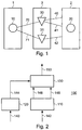
- figure 1 shows a network having a simple configuration in which the method according to the present invention can be applied.
- the network comprises a source domain 1, a destination domain 2 and a transfer domain 3.
- the source domain 1 comprises a source node 10.
- the destination domain 2 comprises a destination node 20.
- the transfer domain 30 comprises a first transfer node 30 and a second transfer node 31.
- the source node 10 is connected to the first transfer node 30 by means of a link 70.
- the source node 10 is connected to the second transfer node 31 by means of a link 71.
- the first transfer node 30 is connected to the destination domain 2 by means of a link 40 and a link 41.
- the second transfer node 31 is connected to the destination domain 2 by means of a link 42.
- the source node 10 is designed for generating and transmitting messages to the destination node 20.
- the transfer nodes 30,31 are designed for relaying the messages, coming from the source node 10, to the destination node 20.
- the source node 10 is for example an international exchange, situated in a first country.
- the destination node 20 is for example an international exchange, situated in a second country. These international exchanges are typically coupled to national signalling networks.
- the source node and the destination node are signalling end points (SEPs).
- the transfer nodes 30,31 are typically signalling transfer points (STPs), situated in the first country.
- the source node 10 and the transfer nodes 30,31 typically are managed by one network operator.
- the destination nodes 20 typically are managed by another network operator.
- the destination network may comprise further transfer nodes and destination nodes but these are not shown in the drawing.
- the transfer nodes in CCITT Common Channel Signalling System No.7 networks are generally designed to re-route messages, when there are faults in the network. Furthermore, the transfer nodes are designed to transmit information related to the network configuration to a Network Management Centre. Finally, the transfer nodes are designed to generate two types of alarms:
- a device 100 is present for representing accessibility states of destination nodes in the network.
- the working of a transfer node is not described in detail in the present application, because it is generally known prior art, described for example in the CCITT Common Channel Signalling System No.7 Recommendation.
- a functional block diagram of the device 100 is shown in figure 2.
- the device is designed to generate alarm states. This function is shown in figure 2 by means of function block 110.
- the generation of alarm states is done on basis of alarms 142 generated by the transfer nodes, which may be of the type I or type II, as described hereinbefore.
- the possible alarm states are, that a link between a transfer node and a destination node is unavailable, which is indicated by arrow 146 or, that a destination node is inaccessible from a transfer node, which is indicated by arrow 148.
- the device 100 is furthermore designed for determining the links between a transfer node and a destination node, which may be used for routing. This function is shown in figure 2 by means of function block 120. The determination of the links, which may be used for routing between a transfer node and a destination node is done on basis of information related to the network configuration 140 coming from the transfer nodes. The information generated by function block 120 is indicated by arrow 144.
- the device 100 furthermore comprises a correlation function, which is indicated by means of function block 130.
- the accessibility state of a destination node as seen from a certain transfer domain is determined (indicated by arrow 150), using the alarm states, indicated by arrows 146, 148 and the information, indicated by arrow 144.
- the following algorithm may be used:
- Transfer nodes is the set of all transfer nodes in the transfer domain
- Destinations is the set of all destination nodes in the destination domain
- Links is a set of all links that are connected to a transfer node in the transfer domain and that are used for routing messages to a destination node.
- a destination node D is given the state "accessible” if all links used to route to destination node D are available and none of the transfer nodes connected to these links have reported incapability of reaching D.
- a destination node is given the state "inaccessible” if all links used to route to destination node D are either unavailable or have a transfer node connected thereto that reported incapability of reaching D.
- transfer node 31 receives a message from destination domain 2 that link 42 cannot be used for routing to destination node 20. As a result, the transfer node 31 sends an alarm message of the type II to the Network Management Centre. Now all links used for routing to destination node 20 are down or have a transfer node connected for which destination node 20 is inaccessible. The algorithm will therefore assign the status "inaccessible" to destination node 20 as seen from transfer domain 3.
- the function blocks 110,120,130 of the device 100 are preferably implemented by a computer device loaded with appropriate software for carrying out these functions.
- the computer device should be connected to a user interface for showing the accessibility state of a destination node as seen from a transfer domain, if this state is "inaccessible” or “degraded".
- a user interface for showing the accessibility state of a destination node as seen from a transfer domain, if this state is "inaccessible” or “degraded”.
- states of individual links indicated by arrow 146) and the accessibility states of destination nodes as seen from an individual transfer node (indicated by arrow 148) are shown by means of this user interface.
- the method of the present invention also may be used in other networks than the telephony signalling network, such as data networks and also in telephony signalling networks having another configuration than the one shown in Figure 1.
Abstract
Description
- an alarm of type I, when a link is unavailable from a transfer node.
- an alarm of type II, when a destination node is inaccessible via the transfer node.
- AccessibleVia (L,D) => Boolean
- Destination node D is accessible via the transfer node connected to link L, i.e., this transfer node has not reported that destination node D is inaccessible
- Available (L) => Boolean
- Link L is available from the transfer node to which it is connected, i.e., this transfer node has not reported that link L is unavailable
- Routed (L,D) => Boolean
- Link L is connected to a transfer node and is used by this transfer node for routing to destination node D
- Accessible (D) => Boolean
- ∀ L ε links : Routed (L,D) => (Available
(L)
∧ AccessibleVia (L,D))
- Inaccessible (D) => Boolean
- ∀ L ε links : Routed (L,D) => (¬Available (L) ∨ ¬AccessibleVia (L,D))
- Degraded (D) => Boolean
- ¬Accessible (D) ∧ ¬Inaccessible (D)
In order to explain the algorithm an example is given with reference to the network shown in figure 1: Suppose that
Suppose now, that also the
Finally,
Claims (2)
- Method of determining accessibility states in a network, the network comprising at least a source node (10) and a destination node (20), which source node (10) generates messages and transmits the messages to the destination node (20), the network further comprising a transfer domain (3), which comprises at least a transfer node (30-31), for relaying the messages between the source node (10) and the destination node (20), wherein the transfer domain (3) can use a plurality of links (40-42) for routing to the destination node (20), characterised in that, individual availability states of the links (40-42) between the transfer domain (3) and the destination domain (2) are monitored, in that at least an accessibility state of the destination node (20), seen from the transfer node (30-31) is monitored and in that, by correlating the individual availability states of the links (40-42) and the accessibility state of the destination node (20) seen from the transfer node (30-31), based on routing data, the accessibility state of the destination node (20), seen from the transfer domain (3), is determined, in which the accessibility is determined to be in a first state, when all the links (40-42) are available and the destination node is accessible from all transfer nodes (30-31) connected to these links (40-42), in which the accessibility is determined to be in a second state, when all the links (40-42) are unavailable or the destination node is inaccessible from all transfer nodes (30-31) connected to these links (40-42) that can route to that destination node (20), and in which the accessibility is determined to be in a third state, when it is determined to be neither in the first state nor in the second state.
- Device for applying the method according to claim 1.
Priority Applications (3)
| Application Number | Priority Date | Filing Date | Title |
|---|---|---|---|
| AT97202687T ATE284113T1 (en) | 1997-09-02 | 1997-09-02 | MESSAGE ROUTING METHOD IN A TELECOMMUNICATION NETWORK AND DEVICE FOR IMPLEMENTING THE METHOD |
| DE69731830T DE69731830T2 (en) | 1997-09-02 | 1997-09-02 | Message routing method in a telecommunications network and apparatus for carrying out the method |
| EP97202687A EP0901295B1 (en) | 1997-09-02 | 1997-09-02 | Method for routing messages in a communication network and device therefor |
Applications Claiming Priority (1)
| Application Number | Priority Date | Filing Date | Title |
|---|---|---|---|
| EP97202687A EP0901295B1 (en) | 1997-09-02 | 1997-09-02 | Method for routing messages in a communication network and device therefor |
Publications (2)
| Publication Number | Publication Date |
|---|---|
| EP0901295A1 true EP0901295A1 (en) | 1999-03-10 |
| EP0901295B1 EP0901295B1 (en) | 2004-12-01 |
Family
ID=8228693
Family Applications (1)
| Application Number | Title | Priority Date | Filing Date |
|---|---|---|---|
| EP97202687A Expired - Lifetime EP0901295B1 (en) | 1997-09-02 | 1997-09-02 | Method for routing messages in a communication network and device therefor |
Country Status (3)
| Country | Link |
|---|---|
| EP (1) | EP0901295B1 (en) |
| AT (1) | ATE284113T1 (en) |
| DE (1) | DE69731830T2 (en) |
Citations (4)
| Publication number | Priority date | Publication date | Assignee | Title |
|---|---|---|---|---|
| EP0621734A2 (en) * | 1993-04-19 | 1994-10-26 | Hewlett-Packard Company | Method and apparatus for monitoring telecommunication networks |
| WO1995012291A1 (en) * | 1993-10-28 | 1995-05-04 | British Telecommunications Public Limited Company | Telecommunications network traffic management system |
| DE4422546A1 (en) * | 1994-06-28 | 1996-01-04 | Alcatel Sel Rft Gmbh | Route list regulation method for switching data network |
| US5488715A (en) * | 1994-08-01 | 1996-01-30 | At&T Corp. | Process for integrated traffic data management and network surveillance in communications networks |
Family Cites Families (1)
| Publication number | Priority date | Publication date | Assignee | Title |
|---|---|---|---|---|
| CA2001665C (en) * | 1988-12-29 | 1993-10-12 | Gerald Richard Ash | Real-time network routing |
-
1997
- 1997-09-02 AT AT97202687T patent/ATE284113T1/en not_active IP Right Cessation
- 1997-09-02 DE DE69731830T patent/DE69731830T2/en not_active Expired - Lifetime
- 1997-09-02 EP EP97202687A patent/EP0901295B1/en not_active Expired - Lifetime
Patent Citations (4)
| Publication number | Priority date | Publication date | Assignee | Title |
|---|---|---|---|---|
| EP0621734A2 (en) * | 1993-04-19 | 1994-10-26 | Hewlett-Packard Company | Method and apparatus for monitoring telecommunication networks |
| WO1995012291A1 (en) * | 1993-10-28 | 1995-05-04 | British Telecommunications Public Limited Company | Telecommunications network traffic management system |
| DE4422546A1 (en) * | 1994-06-28 | 1996-01-04 | Alcatel Sel Rft Gmbh | Route list regulation method for switching data network |
| US5488715A (en) * | 1994-08-01 | 1996-01-30 | At&T Corp. | Process for integrated traffic data management and network surveillance in communications networks |
Non-Patent Citations (6)
| Title |
|---|
| BIJAN JABBARI: "ROUTING AND CONGESTION CONTROL IN COMMON CHANNEL SIGNALING SYSTEM NO. 7", PROCEEDINGS OF THE IEEE, vol. 80, no. 4, 1 April 1992 (1992-04-01), pages 607 - 617, XP000304351 * |
| COAN B A ET AL: "USING DISTRIBUTED TOPOLOGY UPDATE AND PREPLANNED CONFIGURATIONS TO ACHIEVE TRUNK NETWORK SURVIVABILITY", IEEE TRANSACTIONS ON RELIABILITY, vol. 40, no. 4, 1 October 1991 (1991-10-01), pages 404 - 416, XP000232099 * |
| GLITHO R H: "ISOLATING FAULTY ROUTING TABLES IN SS7 NETWORKS: PRESENT AND FUTURE", IEEE COMMUNICATIONS MAGAZINE, vol. 34, no. 5, 1 May 1996 (1996-05-01), pages 98 - 104, XP000574146 * |
| HOUCK D J ET AL: "FAILURE AND CONGESTION PROPAGATION THROUGH SIGNALING CONTROLS", FUNDAMENTAL ROLE OF TELETRAFFIC IN THE EVOLUTION OF TELECOMMUNICATI NETWORKS, PROCEEDINGS OF THE 14TH. INTERNATIONAL TELETRAFFIC CONGRESS - ITC 1 JUAN-LES-PINS, JUNE 6 - 10, 1994, vol. 1A, 6 June 1994 (1994-06-06), LABETOULLE J;ROBERTS J W (EDS ), pages 367 - 376, XP000593427 * |
| MISOON KIM ET AL: "SIGNALING NETWORK OPERATIONS SYSTEM (SIGNOS) IN KOREA", COMMUNICATIONS TECHNOLOGY FOR THE 1990'S AND BEYOND, DALLAS, NOV. 27 - 30, 1989, vol. 2 OF 3, 27 November 1989 (1989-11-27), INSTITUTE OF ELECTRICAL AND ELECTRONICS ENGINEERS, pages 1144 - 1148, XP000144911 * |
| TARLE H: "NETWORK TRAFFIC MANAGEMENT (NTM) USING AXE AND TMOS SYSTEMS", ERICSSON REVIEW, vol. 71, no. 4, 1 January 1994 (1994-01-01), pages 172 - 189, XP000478226 * |
Also Published As
| Publication number | Publication date |
|---|---|
| DE69731830T2 (en) | 2005-12-01 |
| DE69731830D1 (en) | 2005-01-05 |
| ATE284113T1 (en) | 2004-12-15 |
| EP0901295B1 (en) | 2004-12-01 |
Similar Documents
| Publication | Publication Date | Title |
|---|---|---|
| US5042027A (en) | Communication network system and method of controlling a communication network | |
| CA2392942C (en) | Protection system and method for resilient packet ring (rpr) interconnection | |
| CA2220790C (en) | Automatic learning of network routing using random routes | |
| US20020118636A1 (en) | Mesh network protection using dynamic ring | |
| MX2022009750A (en) | Routing communication in telecommunications network having multiple service communication proxies. | |
| US5444773A (en) | Method for releasing unnecessary trucks from a telephone call | |
| JP3002260B2 (en) | How to prevent circular routing in telecommunications networks | |
| US7711828B2 (en) | Communication between call controllers by amending call processing messages | |
| EP1271969A2 (en) | Signaling gateway system and network management method | |
| US6859431B1 (en) | System and method for calculating protection routes in a network prior to failure | |
| EP0901295B1 (en) | Method for routing messages in a communication network and device therefor | |
| US7002906B1 (en) | Method for extending the crankback procedure to any Asynchronous Transfer Mode system | |
| US6418117B1 (en) | Out of band messaging in a DRA network | |
| Segall et al. | A recoverable protocol for loop-free distributed routing | |
| US6212187B1 (en) | Multiprocessor ATM exchange | |
| JP4365763B2 (en) | Multilayer network, relay node device, and redundant path establishment method | |
| KR100336942B1 (en) | Transfer Message Broadcasting Method In Signaling Transfer Point | |
| KR100441487B1 (en) | Method for signaling monitoring in No.7 signaling network | |
| KR100476481B1 (en) | Method For Transmitting Message Between Signaling Points In No.7 Signaling Network | |
| KR100371688B1 (en) | Function Trace and Surveillance Mehtod in Communication System | |
| KR100337297B1 (en) | Signaling Traffic Load Sharing Method Between Combined Linkset In No.7 Network | |
| JP2845189B2 (en) | ATM switching network call admission control method and apparatus | |
| JP3513022B2 (en) | ATM communication network | |
| KR100353085B1 (en) | method for signal routing route management in No.7 signaling network | |
| KR100350314B1 (en) | Method For Processing In Case Of Routing Failure Of Signal Message In A No.7 Signalling Network |
Legal Events
| Date | Code | Title | Description |
|---|---|---|---|
| PUAI | Public reference made under article 153(3) epc to a published international application that has entered the european phase |
Free format text: ORIGINAL CODE: 0009012 |
|
| AK | Designated contracting states |
Kind code of ref document: A1 Designated state(s): AT BE CH DE DK ES FI FR GB GR IE IT LI LU NL PT SE |
|
| AX | Request for extension of the european patent |
Free format text: AL;LT;LV;RO;SI |
|
| 17P | Request for examination filed |
Effective date: 19990910 |
|
| AKX | Designation fees paid |
Free format text: AT BE CH DE DK ES FI FR GB GR IE IT LI LU NL PT SE |
|
| GRAP | Despatch of communication of intention to grant a patent |
Free format text: ORIGINAL CODE: EPIDOSNIGR1 |
|
| GRAS | Grant fee paid |
Free format text: ORIGINAL CODE: EPIDOSNIGR3 |
|
| GRAA | (expected) grant |
Free format text: ORIGINAL CODE: 0009210 |
|
| AK | Designated contracting states |
Kind code of ref document: B1 Designated state(s): AT BE CH DE DK ES FI FR GB GR IE IT LI LU NL PT SE |
|
| PG25 | Lapsed in a contracting state [announced via postgrant information from national office to epo] |
Ref country code: FI Free format text: LAPSE BECAUSE OF FAILURE TO SUBMIT A TRANSLATION OF THE DESCRIPTION OR TO PAY THE FEE WITHIN THE PRESCRIBED TIME-LIMIT Effective date: 20041201 Ref country code: AT Free format text: LAPSE BECAUSE OF FAILURE TO SUBMIT A TRANSLATION OF THE DESCRIPTION OR TO PAY THE FEE WITHIN THE PRESCRIBED TIME-LIMIT Effective date: 20041201 |
|
| REG | Reference to a national code |
Ref country code: GB Ref legal event code: FG4D |
|
| REG | Reference to a national code |
Ref country code: CH Ref legal event code: NV Representative=s name: ISLER & PEDRAZZINI AG Ref country code: CH Ref legal event code: EP |
|
| REG | Reference to a national code |
Ref country code: IE Ref legal event code: FG4D |
|
| REF | Corresponds to: |
Ref document number: 69731830 Country of ref document: DE Date of ref document: 20050105 Kind code of ref document: P |
|
| PG25 | Lapsed in a contracting state [announced via postgrant information from national office to epo] |
Ref country code: SE Free format text: LAPSE BECAUSE OF FAILURE TO SUBMIT A TRANSLATION OF THE DESCRIPTION OR TO PAY THE FEE WITHIN THE PRESCRIBED TIME-LIMIT Effective date: 20050301 Ref country code: GR Free format text: LAPSE BECAUSE OF FAILURE TO SUBMIT A TRANSLATION OF THE DESCRIPTION OR TO PAY THE FEE WITHIN THE PRESCRIBED TIME-LIMIT Effective date: 20050301 Ref country code: DK Free format text: LAPSE BECAUSE OF FAILURE TO SUBMIT A TRANSLATION OF THE DESCRIPTION OR TO PAY THE FEE WITHIN THE PRESCRIBED TIME-LIMIT Effective date: 20050301 |
|
| PG25 | Lapsed in a contracting state [announced via postgrant information from national office to epo] |
Ref country code: ES Free format text: LAPSE BECAUSE OF FAILURE TO SUBMIT A TRANSLATION OF THE DESCRIPTION OR TO PAY THE FEE WITHIN THE PRESCRIBED TIME-LIMIT Effective date: 20050312 |
|
| PG25 | Lapsed in a contracting state [announced via postgrant information from national office to epo] |
Ref country code: IE Free format text: LAPSE BECAUSE OF NON-PAYMENT OF DUE FEES Effective date: 20050902 |
|
| PG25 | Lapsed in a contracting state [announced via postgrant information from national office to epo] |
Ref country code: LU Free format text: LAPSE BECAUSE OF NON-PAYMENT OF DUE FEES Effective date: 20050930 |
|
| PLBE | No opposition filed within time limit |
Free format text: ORIGINAL CODE: 0009261 |
|
| STAA | Information on the status of an ep patent application or granted ep patent |
Free format text: STATUS: NO OPPOSITION FILED WITHIN TIME LIMIT |
|
| ET | Fr: translation filed | ||
| 26N | No opposition filed |
Effective date: 20050902 |
|
| REG | Reference to a national code |
Ref country code: IE Ref legal event code: MM4A |
|
| REG | Reference to a national code |
Ref country code: CH Ref legal event code: PCAR Free format text: ISLER & PEDRAZZINI AG;POSTFACH 1772;8027 ZUERICH (CH) |
|
| PG25 | Lapsed in a contracting state [announced via postgrant information from national office to epo] |
Ref country code: PT Free format text: LAPSE BECAUSE OF NON-PAYMENT OF DUE FEES Effective date: 20050501 |
|
| REG | Reference to a national code |
Ref country code: CH Ref legal event code: PUE Owner name: CISCO SYSTEMS, INC. Free format text: KONINKLIJKE KPN N.V.#STATIONSPLEIN 7#9726 AE GRONINGEN (NL) -TRANSFER TO- CISCO SYSTEMS, INC.#170 WEST TASMAN DR.#SAN JOSE, CA 95134-1706 (US) Ref country code: CH Ref legal event code: PUE Owner name: CISCO TECHNOLOGY, INC. Free format text: CISCO SYSTEMS, INC.#170 WEST TASMAN DR.#SAN JOSE, CA 95134-1706 (US) -TRANSFER TO- CISCO TECHNOLOGY, INC.#170 WEST TASMAN DR.#SAN JOSE, CA 95134-1706 (US) |
|
| REG | Reference to a national code |
Ref country code: NL Ref legal event code: SD Effective date: 20100914 |
|
| BECH | Be: change of holder |
Owner name: CISCO TECHNOLOGY INC. Effective date: 20101119 |
|
| REG | Reference to a national code |
Ref country code: FR Ref legal event code: TP |
|
| REG | Reference to a national code |
Ref country code: DE Ref legal event code: R081 Ref document number: 69731830 Country of ref document: DE Owner name: CISCO TECHNOLOGY, INC., SAN JOSE, US Free format text: FORMER OWNER: KONINKLIJKE KPN N.V., GRONINGEN, NL Effective date: 20110330 |
|
| REG | Reference to a national code |
Ref country code: FR Ref legal event code: PLFP Year of fee payment: 19 |
|
| PGFP | Annual fee paid to national office [announced via postgrant information from national office to epo] |
Ref country code: CH Payment date: 20150928 Year of fee payment: 19 Ref country code: GB Payment date: 20150928 Year of fee payment: 19 |
|
| PGFP | Annual fee paid to national office [announced via postgrant information from national office to epo] |
Ref country code: BE Payment date: 20150928 Year of fee payment: 19 Ref country code: FR Payment date: 20150917 Year of fee payment: 19 |
|
| PGFP | Annual fee paid to national office [announced via postgrant information from national office to epo] |
Ref country code: IT Payment date: 20150923 Year of fee payment: 19 |
|
| PGFP | Annual fee paid to national office [announced via postgrant information from national office to epo] |
Ref country code: DE Payment date: 20150929 Year of fee payment: 19 |
|
| PGFP | Annual fee paid to national office [announced via postgrant information from national office to epo] |
Ref country code: NL Payment date: 20150926 Year of fee payment: 19 |
|
| PG25 | Lapsed in a contracting state [announced via postgrant information from national office to epo] |
Ref country code: BE Free format text: LAPSE BECAUSE OF NON-PAYMENT OF DUE FEES Effective date: 20160930 |
|
| REG | Reference to a national code |
Ref country code: DE Ref legal event code: R119 Ref document number: 69731830 Country of ref document: DE |
|
| REG | Reference to a national code |
Ref country code: CH Ref legal event code: PL |
|
| REG | Reference to a national code |
Ref country code: NL Ref legal event code: MM Effective date: 20161001 |
|
| GBPC | Gb: european patent ceased through non-payment of renewal fee |
Effective date: 20160902 |
|
| PG25 | Lapsed in a contracting state [announced via postgrant information from national office to epo] |
Ref country code: NL Free format text: LAPSE BECAUSE OF NON-PAYMENT OF DUE FEES Effective date: 20161001 |
|
| REG | Reference to a national code |
Ref country code: FR Ref legal event code: ST Effective date: 20170531 |
|
| PG25 | Lapsed in a contracting state [announced via postgrant information from national office to epo] |
Ref country code: GB Free format text: LAPSE BECAUSE OF NON-PAYMENT OF DUE FEES Effective date: 20160902 Ref country code: CH Free format text: LAPSE BECAUSE OF NON-PAYMENT OF DUE FEES Effective date: 20160930 Ref country code: DE Free format text: LAPSE BECAUSE OF NON-PAYMENT OF DUE FEES Effective date: 20170401 Ref country code: LI Free format text: LAPSE BECAUSE OF NON-PAYMENT OF DUE FEES Effective date: 20160930 Ref country code: FR Free format text: LAPSE BECAUSE OF NON-PAYMENT OF DUE FEES Effective date: 20160930 |
|
| PG25 | Lapsed in a contracting state [announced via postgrant information from national office to epo] |
Ref country code: IT Free format text: LAPSE BECAUSE OF NON-PAYMENT OF DUE FEES Effective date: 20160902 |
|
| REG | Reference to a national code |
Ref country code: BE Ref legal event code: MM Effective date: 20160930 |