EP0901197A2 - Self-aligning connector system for electrical connectors - Google Patents
Self-aligning connector system for electrical connectors Download PDFInfo
- Publication number
- EP0901197A2 EP0901197A2 EP98116386A EP98116386A EP0901197A2 EP 0901197 A2 EP0901197 A2 EP 0901197A2 EP 98116386 A EP98116386 A EP 98116386A EP 98116386 A EP98116386 A EP 98116386A EP 0901197 A2 EP0901197 A2 EP 0901197A2
- Authority
- EP
- European Patent Office
- Prior art keywords
- aligning
- housing
- deflectable
- mounting
- self
- Prior art date
- Legal status (The legal status is an assumption and is not a legal conclusion. Google has not performed a legal analysis and makes no representation as to the accuracy of the status listed.)
- Granted
Links
Images


Classifications
-
- H—ELECTRICITY
- H01—ELECTRIC ELEMENTS
- H01R—ELECTRICALLY-CONDUCTIVE CONNECTIONS; STRUCTURAL ASSOCIATIONS OF A PLURALITY OF MUTUALLY-INSULATED ELECTRICAL CONNECTING ELEMENTS; COUPLING DEVICES; CURRENT COLLECTORS
- H01R13/00—Details of coupling devices of the kinds covered by groups H01R12/70 or H01R24/00 - H01R33/00
- H01R13/62—Means for facilitating engagement or disengagement of coupling parts or for holding them in engagement
- H01R13/629—Additional means for facilitating engagement or disengagement of coupling parts, e.g. aligning or guiding means, levers, gas pressure electrical locking indicators, manufacturing tolerances
- H01R13/631—Additional means for facilitating engagement or disengagement of coupling parts, e.g. aligning or guiding means, levers, gas pressure electrical locking indicators, manufacturing tolerances for engagement only
- H01R13/6315—Additional means for facilitating engagement or disengagement of coupling parts, e.g. aligning or guiding means, levers, gas pressure electrical locking indicators, manufacturing tolerances for engagement only allowing relative movement between coupling parts, e.g. floating connection
-
- H—ELECTRICITY
- H01—ELECTRIC ELEMENTS
- H01R—ELECTRICALLY-CONDUCTIVE CONNECTIONS; STRUCTURAL ASSOCIATIONS OF A PLURALITY OF MUTUALLY-INSULATED ELECTRICAL CONNECTING ELEMENTS; COUPLING DEVICES; CURRENT COLLECTORS
- H01R13/00—Details of coupling devices of the kinds covered by groups H01R12/70 or H01R24/00 - H01R33/00
- H01R13/46—Bases; Cases
- H01R13/502—Bases; Cases composed of different pieces
- H01R13/506—Bases; Cases composed of different pieces assembled by snap action of the parts
-
- H—ELECTRICITY
- H01—ELECTRIC ELEMENTS
- H01R—ELECTRICALLY-CONDUCTIVE CONNECTIONS; STRUCTURAL ASSOCIATIONS OF A PLURALITY OF MUTUALLY-INSULATED ELECTRICAL CONNECTING ELEMENTS; COUPLING DEVICES; CURRENT COLLECTORS
- H01R13/00—Details of coupling devices of the kinds covered by groups H01R12/70 or H01R24/00 - H01R33/00
- H01R13/46—Bases; Cases
- H01R13/516—Means for holding or embracing insulating body, e.g. casing, hoods
- H01R13/518—Means for holding or embracing insulating body, e.g. casing, hoods for holding or embracing several coupling parts, e.g. frames
-
- H—ELECTRICITY
- H01—ELECTRIC ELEMENTS
- H01R—ELECTRICALLY-CONDUCTIVE CONNECTIONS; STRUCTURAL ASSOCIATIONS OF A PLURALITY OF MUTUALLY-INSULATED ELECTRICAL CONNECTING ELEMENTS; COUPLING DEVICES; CURRENT COLLECTORS
- H01R13/00—Details of coupling devices of the kinds covered by groups H01R12/70 or H01R24/00 - H01R33/00
- H01R13/73—Means for mounting coupling parts to apparatus or structures, e.g. to a wall
- H01R13/74—Means for mounting coupling parts in openings of a panel
Definitions
- This invention generally relates to the art of electrical connectors and, particularly, to a self-aligning connector system for facilitating mating an electrical connector assembly to a complementary mating connector.
- electrical connectors typically include a housing mounting a plurality of electrically conductive terminals therein.
- the housing usually is fabricated of nonconductive material and may be partly or entirely molded from plastic.
- the housing includes a mating end with structure that permits mating and unmating with a second electrical connector.
- the second electrical connector may be mounted to wires, a cable, a circuit board or other electrical lead means.
- the panel may be mountable in an aperture in the support structure.
- Many prior art connectors of this general type include separate means for achieving secure mounting of the connector to the support structure.
- separate retaining means such as bolts, clips or the like rigidly secure the connector housing to the support structure.
- Integral latches also have been used to avoid the need for separate retaining means.
- the latches typically are molded integrally with the connector housing to reduce costs, to facilitate assembly and to avoid inventory control problems.
- the present invention is directed to providing various features in an electrical connector and its mounting system that improves the manufacturability, the assembly and/or the use of electrical connectors in environments wherein it is desirable to have some degree of movement of the connector relative to its mounting support structure and to facilitate mating the electrical connector to a complementary mating assembly.
- An object, therefore, of the invention is to provide a new and improved self-aligning connector system for facilitating mating an electrical connector assembly to a complementary mating connector.
- the electrical connector assembly is adapted to be mounted within a mounting aperture of an appropriate support structure.
- the system includes a housing having a forward end for insertion into the mounting aperture, a rearward end and side walls extending between the ends.
- At least one deflectable aligning beam is cantilevered from at least one side wall of the housing for engaging an edge of the mounting aperture and exerting forces on the support structure for aligning the housing in the mounting aperture.
- Detent means are operatively associated between the housing and the aligning beam for holding the beam in an inoperative condition spaced from the side wall of the housing and for allowing the beam to release upon mating to the complementary connector to a deflectable condition which facilitates alignment of the connectors.
- the aligning beam is moved to its deflectable condition upon mating of the electrical connector assembly to its complementary connector.
- the detent means also allow the beam to be manually moved back to its inoperative condition if the beam is inadvertently moved to its deflectable condition prior to mating the connectors.
- the deflectable aligning beam has a fixed forward end and a releasable held rearward end.
- the detent means is located at the rearward end of the arm.
- the detent means is disclosed as a snap-latch means for releasably holding the deflectable aligning beam in its inoperative condition.
- the housing is rectangular with a plurality of generally straight side walls. At least one of the deflectable aligning beams is provided on each side wall.
- frangible break-away means between the housing and the deflectable aligning beam for holding the beam in its inoperative condition.
- the housing including the deflectable aligning beam, is molded of dielectric plastic material, and the frangible break-away means comprises an integrally molded web.
- the break-away means can provide a redundant means (i.e. in addition to the detent means) for holding the deflectable aligning beam in its inoperative condition.
- the break-away means can provide a separate system for holding the beam in its inoperative condition.
- the electrical connector aligning system and other features of the invention are particularly applicable for use in automotive applications, such as in an automobile, generally designated 22.
- the automobile is shown in reference to various axes as might be referenced in an automotive assembly line.
- Double-headed arrow 24 represents the "X" axis running horizontally in a front-to-rear direction of the automobile.
- Double-headed arrow 26 represents the horizontal axis "Y” running transversely of the automobile.
- Double-headed arrow 28 represents the "Z" or vertical axis.
- the mounting system and other features of the invention are equally applicable for a wide variety of applications other than that simply of automotive or other vehicular uses.
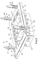
- FIGURE 2 shows an exploded perspective depiction of an overall electrical connector assembly mounting arrangement as might be used in assembling automobile 22.
- a support structure, generally designated 30, in the form of a U-shaped main bracket is secured to a panel 32 behind the dash board of the automobile.
- the main support bracket includes a face plate 34 spaced from panel 32.
- the face plate includes an upper pair of generally round mounting holes 36 and a lower pair of generally round mounting holes 38.
- mounting holes 38 are spaced wider than mounting holes 36.
- a receptacle holding assembly is mounted to support structure 30.
- the receptacle holding assembly includes an outer bracket or frame structure, generally designated 42, and an inner bracket or housing, generally designated 44.
- the entire receptacle holding assembly 40 is provided with self-alignment relative to support structure 30 in the "X" (Fig. 1) axis
- inner bracket or housing 44 is provided with self-alignment relative to outer bracket or frame structure 42 in the "Y" and "Z" axes.
- a complementary mating second connector is connectable with receptacle holding assembly 40, particularly inner bracket or housing 44.
- Mating connector 46 may be secured to the rear of the dashboard of the vehicle and the entire assembly moved toward panel 32 for engaging connector 46 with receptacle holding assembly 40.
- Mating connector 46 houses three connector subassemblies 48 which respectively mount a plurality of electrical terminals.
- Inner housing 44 of receptacle holding assembly 40 includes three receptacles 50 which house three modular connectors (not shown) which respectively mount a plurality of electrical terminals for interconnection with the terminals of connectors 48.
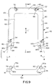
- FIGs 3-8 show in greater detail the assembly of receptacle holding assembly 40 (Fig. 1).
- receptacle holding assembly 40 includes outer bracket or frame structure 42 and inner bracket or housing 44 with its three receptacles 50.
- outer frame structure 42 includes two pairs of mounting posts, generally designated 52 and 54, for insertion into the two pairs of mounting holes 36 and 38, respectively, in main bracket or support structure 30 (Fig. 2).
- Outer frame structure 42 defines a mounting aperture 56 which is seen best in Figures 4 and 5, within which inner housing 44 is mounted.
- inner housing 44 includes peripheral side flanges 58 which slide into guide tracks 60 in outer frame structure 42.
- FIGS. 9-15 show in greater detail the specific structure of outer bracket or frame structure 42 of receptacle holding assembly 40. More particularly, outer frame structure 42 is a two-part structure including a generally U-shaped first frame piece, generally designated 62, and an elongated second frame piece, generally designated 64. The frame pieces are shown disassembled in FIGURE 9. When the frame pieces are assembled, they define closed mounting aperture 56 within which inner bracket or housing 44 (Fig. 2) is mounted.
- the U-shaped first frame piece 62 of outer frame structure 42 includes a pair of generally parallel arms 66 joined by a cross-arm 68 which defines the bight portion of the U-shaped configuration.
- Parallel arms 66 define an open side 70 of the first frame piece which, in assembly, is closed by second frame piece 64.
- First frame piece 62 has a pair of flexible latch arms 72 cantilevered from the outside of distal ends 66a of arms 66 as best seen in FIGURE 9.
- the arms have openings to define latch shoulders 72a as best seen in Figures 10 and 12.
- latch arms 72 are inserted through a pair of bridges 74 at opposite ends of second frame piece 64 in the direction of arrows "A" (Fig. 9).
- latch shoulders 72a of the flexible cantilevered latch arms snap behind latch bosses 76 (Fig. 13) located inside bridges 74 of the second frame piece.
- bridges 74 provide an anti-overstress means to prevent cantilevered latch arms 72 from being pulled outwardly from the assembly which might break or overstress the latch arms.
- Second frame piece 62 Side arms 66 of first frame piece 62 have flared flanges 66b projecting axially from distal ends 66a of the arms as best seen in Figures 9-12. This facilitates guiding flanges 58 (Figs. 7 and 8) of inner housing 44 into guide tracks 60 within the arms of first frame piece 62.
- first and second frame pieces 62 and 64 respectively, include complementary interengaging spacing means between opposite ends of second frame piece 64 and the free or distal ends 66a of arms 66 of the U-shaped first frame piece 62, to maintain a predetermined spacing between arms 66.
- second frame piece 64 includes a pair of outer tabs 78 defining inwardly facing camming surfaces 78a, and a pair of inner tabs 80 defining outwardly facing camming surfaces 80a.
- Distal ends 66a of arms 66 of first frame piece 62 include outer tabs 82 having inwardly facing camming surfaces 82a and flared flanges 66b define outwardly facing camming surfaces 84. It can be seen that the tips of tabs 78 and 80 are tapered or chamfered to facilitate engagement of the various camming surfaces on the two frame pieces.
- the complementary interengaging spacing means provided by tabs 78,80,82 and flanges 66b, along with their respective camming surfaces, provide a means for maintaining precise spacing between side arms 66 of the U-shaped first frame piece 62.
- side legs 66 may not be at a desired predetermined spacing. Therefore, the assembly of second frame piece 64 to the U-shaped frame piece will establish the precise spacing.
- camming surfaces 78a of outer tabs 78 will engage camming surfaces 84 of flared flanges 66b to draw arms 66 inwardly toward their precise spacing. This engagement can be seen in FIGURE 5.
- camming surfaces 80a of tabs 80 will engage camming surface 82a of tabs 82 and move the arms outwardly toward their precise spacing. This engagement can be seen in FIGURE 4.
- FIGs 2-4, 9, 10 and 15 show a unique configuration of mounting posts 52 and 54 of outer bracket or frame structure 42.
- the mounting posts project from the U-shaped first frame piece 62 of the outer bracket or frame structure.
- the pair of mounting posts 52 are spaced closer together than the pair of mounting posts 54. Therefore, mounting posts 52 are insertable into round holes 36 (Fig. 2) of main support bracket 30, and mounting posts 54 are insertable into holes 38 in the main support bracket. The reason for this differential spacing of the respective pairs of mounting posts will be described below. Otherwise, each mounting post has an identical structural configuration.
- each mounting post 52,54 has a generally round envelope as defined by three rigid crush ribs 86 extending lengthwise of the post and spaced from each other circumferentially about a major side 88 of the post as best seen in Figures 15A-15C.
- at least a pair of the crush ribs are diametrically disposed on opposite sides of the post.
- three of the crush ribs are equally spaced relative to each other in three quadrants about the post as best seen in FIGURE 15B.
- a flexible arm 90 extends lengthwise of each post on a side of the post opposite major side 88, i.e.
- the flexible arm has opposite ends 90a fixed to the post and spaced outwardly therefrom to define a flexing space 92 behind the arm as best seen in Figures 15A and 15C. Therefore, the flexible arms can flex relative to the post in the direction of double-headed arrow "B" (Fig. 15C).
- a latch hook 90b is formed on the outside of flexible arm 90 intermediate opposite ends 90a thereof.
- the tip of each post is tapered or pointed, as at 94, to facilitate insertion into its respective hole 36,38 of main support bracket 30.
- each mounting post 52 (54) is such that the effective diameter of the post defined by crush ribs 86 and flexible arm 90 is greater than the diameter of mounting holes 36 and 38. Therefore, arm 90 will flex and ribs 86 will at least partially crush when the post is inserted into its respective mounting hole.
- latch hook 90b is closer to the distal end of the mounting post than the outer ends 86a of crush ribs 86. This differential in axial spacing between the latch hooks of the mounting posts and the ends of the crushed ribs provide a preliminary mounting position for receptacle holding assembly 40 (Fig. 2) on main support bracket 30, before crush ribs 80 begin to deform.
- mating second connector 46 (Fig. 2) is mated with receptacle holding assembly 40 along the "X" axis (Fig. 1).
- the terminals of connectors 48 of mating connector 46 interengage with the terminals of the modular connectors within receptacles 50 of inner housing 44 while receptacle holding assembly 40 is in its preliminary mounting position defined by latch hooks 90b of mounting posts 52,54 (i.e. before any deformation of crush ribs 86).
- crush ribs 86 are capable of deforming to accommodate this overtravel and still securely mount receptacle holding assembly 40 to main support bracket 30.
- One embodiment of the invention facilitates maintaining a substantially constant insertion force of mounting posts 52,54 into mounting holes 36,38. More particularly, as best seen in FIGURE 15A, the width of the crush ribs as well as the thickness of the crush ribs are gradually reduced from ends 86a of the ribs toward arms 66 of outer bracket 42. The crush ribs are gradually reduced in cross section in a direction away from distal ends 86a of the ribs to facilitate maintaining a substantially constant insertion force of the mounting posts into the mounting holes. This gradual reduction in the cross sectional dimensions of the crush ribs also reduces the build-up of plastic fragments caused by deformation of the ribs. However, it is not necessary to the invention that the cross section of the crush ribs be reduced. In some applications, the cross section of the crush ribs may be maintained at a constant dimension or at a gradually increasing dimension depending on the insertion and retention force requirements thereof.
- FIGURE 2 shows that mounting holes 36 (for mounting posts 52) are spaced closer together than mounting holes 38 (for mounting posts 54).
- the purpose of this differential spacing is to facilitate molding U-shaped frame piece 62 (Fig. 9) in a simple molding fixture having two mold parts which are separable in a mold direction represented by double-headed arrow "C" (Fig. 9).
- frame piece 62 including guide tracks 60, latch arms 72 and the other components at the distal ends 66a of arms 66 can be molded in a separable two-part mold without any side coring.
- the mounting posts are offset relative to each other transversely of mold direction "C" so that no two posts are in alignment in the mold direction.
- flexing spaces 92 of all of the mounting posts are open in the mold direction so that the mounting posts, along with the other elements of frame piece 62 can be molded with the simple two-part mold.
- the offset mounting posts serve the additional purpose of polarizing receptacle holding assembly 40 with respect to main support bracket 30 such that it is oriented properly.
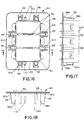
- Figures 16-21 show in greater detail the specific structure of inner bracket or housing 44 which is mounted within outer bracket or frame structure 42 of receptacle holding assembly 40. More particularly, as stated above, inner housing 44 includes the peripheral flange 58 which slides into guide tracks 60 (Fig. 7) of the U-shaped frame piece of outer frame structure 42. In addition, as stated above, inner housing 44 has three receptacles 50 for mounting appropriate modular connectors (not shown) for mating with complementary connectors 48 (Fig. 2) of mating connector 46. Inner housing 44 is mounted in outer frame structure 42 so that the receptacles project through mounting aperture 56 in the outer frame structure as best seen in FIGURE 2. Finally, inner housing 44 has a unique self-aligning mounting system for mounting the entire inner housing and its modular connectors within outer frame structure 42.
- inner housing 44 includes two deflectable aligning beams 98 cantilevered from each of the four side walls 100 which define receptacles 50.
- the deflectable aligning beams are positioned for engagement with the four edges of mounting aperture 56 in outer frame structure 42.
- Each deflectable aligning beam 98 has a fixed forward end 98a and a releasably held rearward or distal end 98b.
- the fixed end is considered “forward", because, as seen in FIGURE 2, the deflectable aligning beams are cantilevered rearwardly from a forward mating end 102 of inner housing 44.
- FIGURE 21 best shows one of the deflectable aligning beams 98 with its forward end 98a and its distal end 98b.
- detent means are operatively associated between inner housing 44 and each deflectable aligning beam 98 for holding the beam in an inoperative condition spaced outwardly of the side wall 100 of the housing, whereby the beam can be released to a deflectable condition to facilitate self-aligning inner housing 44 during mating with complementary mating connector 46.
- distal end 98b of each deflectable aligning beam 98 projects into a respective opening 104 in peripheral flange 58 of inner housing 44, as best seen in FIGURE 16 and the enlarged depictions of Figures 20 and 21.
- a pair of detent bosses 106 project inwardly from opposite sides of each opening 104 behind the distal end of the respective deflectable aligning beam 98 extending into the opening.
- detent bosses 106 hold the deflectable aligning beams in inoperative (i.e. non-flexing) condition.
- the aligning beams are held in their inoperative or preload condition during assembly, to maintain inner housing 44 centered within mounting aperture 56 in outer frame structure 42.
- the invention also contemplates a redundant means to hold deflectable aligning beams 98 in their inoperative (i.e. non-flexing) condition.
- a frangible or break-away web 108 is integrally molded between each deflectable aligning beam 98 and inner housing 44. It can be seen that the break-away web is located on the outside of the distal end 98b of the aligning beam and the inside wall of opening 104. When it is desired to move the deflectable aligning beams out of their pre-load or inoperative positions, the break-away webs are broken and the distal ends of the beams are free from attachment to the housing.
- inner housing 44 is provided with a latch 110 projecting outwardly from the side wall 100 at each opposite end of the housing for latching engagement with complementary mating second connector 46.
- Figure 2 shows one of the latches 110 for latching engagement with a complementary latch 112 on the mating second connector.
Abstract
Description
- This invention generally relates to the art of electrical connectors and, particularly, to a self-aligning connector system for facilitating mating an electrical connector assembly to a complementary mating connector.
- Generally, electrical connectors typically include a housing mounting a plurality of electrically conductive terminals therein. The housing usually is fabricated of nonconductive material and may be partly or entirely molded from plastic. The housing includes a mating end with structure that permits mating and unmating with a second electrical connector. The second electrical connector may be mounted to wires, a cable, a circuit board or other electrical lead means.
- Often, electrical connectors are mounted in a panel or other appropriate support structure, the panel may be mountable in an aperture in the support structure. Many prior art connectors of this general type include separate means for achieving secure mounting of the connector to the support structure. For example, separate retaining means, such as bolts, clips or the like rigidly secure the connector housing to the support structure. Integral latches also have been used to avoid the need for separate retaining means. The latches typically are molded integrally with the connector housing to reduce costs, to facilitate assembly and to avoid inventory control problems.
- On the other hand, many electrical connectors are employed in blind mating environments wherein precise alignment of the connectors during mating cannot always be assured. For example, an electrical connector mounted to a panel or other appropriate support structure may be disposed at a relatively inaccessible location in an automobile or other vehicle. Even if the connector location is not actually inaccessible, it often is desirable to provide for a degree of relative movement between the electrical connector and its support structure during mating with the second electrical connector. Without such movement, attempts to mate improperly aligned connectors can result in substantial damage to one or both connectors and/or to the fragile electrically conductive terminals mounted therein, thereby resulting in a poor quality electrical connection or no electrical connection at all.
- The present invention is directed to providing various features in an electrical connector and its mounting system that improves the manufacturability, the assembly and/or the use of electrical connectors in environments wherein it is desirable to have some degree of movement of the connector relative to its mounting support structure and to facilitate mating the electrical connector to a complementary mating assembly.
- An object, therefore, of the invention is to provide a new and improved self-aligning connector system for facilitating mating an electrical connector assembly to a complementary mating connector. The electrical connector assembly is adapted to be mounted within a mounting aperture of an appropriate support structure.
- In the exemplary embodiment of the invention, the system includes a housing having a forward end for insertion into the mounting aperture, a rearward end and side walls extending between the ends. At least one deflectable aligning beam is cantilevered from at least one side wall of the housing for engaging an edge of the mounting aperture and exerting forces on the support structure for aligning the housing in the mounting aperture. Detent means are operatively associated between the housing and the aligning beam for holding the beam in an inoperative condition spaced from the side wall of the housing and for allowing the beam to release upon mating to the complementary connector to a deflectable condition which facilitates alignment of the connectors. The aligning beam is moved to its deflectable condition upon mating of the electrical connector assembly to its complementary connector. The detent means also allow the beam to be manually moved back to its inoperative condition if the beam is inadvertently moved to its deflectable condition prior to mating the connectors.
- As disclosed herein, the deflectable aligning beam has a fixed forward end and a releasable held rearward end. The detent means is located at the rearward end of the arm. The detent means is disclosed as a snap-latch means for releasably holding the deflectable aligning beam in its inoperative condition. In the preferred embodiment, the housing is rectangular with a plurality of generally straight side walls. At least one of the deflectable aligning beams is provided on each side wall.
- Another feature of the invention is the provision of frangible break-away means between the housing and the deflectable aligning beam for holding the beam in its inoperative condition. The housing, including the deflectable aligning beam, is molded of dielectric plastic material, and the frangible break-away means comprises an integrally molded web. The break-away means can provide a redundant means (i.e. in addition to the detent means) for holding the deflectable aligning beam in its inoperative condition. However, it is contemplated that the break-away means can provide a separate system for holding the beam in its inoperative condition.
- Other objects, features and advantages of the invention will be apparent from the following detailed description taken in connection with the accompanying drawings.
- The features of this invention which are believed to be novel are set forth with particularity in the appended claims. The invention, together with its objects and the advantages thereof, may be best understood by reference to the following description taken in conjunction with the accompanying drawings, in which like reference numerals identify like elements in the figures and in which:
- FIGURE 1 is a somewhat schematic perspective view of an automobile as it might travel relative to an assembly line, showing the various assembly axes;
- FIGURE 2 is an exploded perspective view of the electrical assembly and mounting system of the invention;
- FIGURE 3 is a perspective view of the rear side of the receptacle holding assembly;
- FIGURE 4 is a rear elevation of the receptacle holding assembly;
- FIGURE 5 is a front elevation of the receptacle holding assembly;
- FIGURE 6 is a bottom plan view of the receptacle holding assembly;
- FIGURE 7 is a horizontal section taken generally along line 7-7 of Figure 5;
- FIGURE 8 is a vertical section taken generally along line 8-8 of Figure 5;
- FIGURE 9 is a rear elevation of the outer bracket or frame structure of the receptacle holding assembly, in disassembled condition;
- FIGURE 10 is a vertical section taken generally along line 10-10 of Figure 9;
- FIGURE 11 is a side elevational view of the U-shaped portion of the outer bracket;
- FIGURE 12 is a vertical section taken generally along line 12-12 of Figure 11;
- FIGURE 13 is a bottom plan view of the second portion of the outer bracket;
- FIGURE 14 is a fragmented section taken generally along line 14-14 of Figure 13;
- FIGURE 15A is a side elevational view of one of the mounting posts of the outer bracket;
- FIGURE 15B is an end view of one of the mounting posts;
- FIGURE 15C is a section taken generally along
line 15C-15C of Figure 15B; - FIGURE 16 is a rear elevation of the inner bracket or housing of the receptacle holding assembly;
- FIGURE 17 is a side elevational view of the inner bracket, looking toward the right-hand side of Figure 16;
- FIGURE 18 is a bottom plan view of the inner bracket;
- FIGURE 19 is a horizontal section taken generally along line 19-19 of Figure 16;
- FIGURE 20 is an enlarged view of the detent area for one of the aligning beams of the inner bracket; and
- FIGURE 21 is a further enlarged section taken generally along line 21-21 of Figure 20.
-
- Referring to the drawings in greater detail, and first to Figure 1, the electrical connector aligning system and other features of the invention are particularly applicable for use in automotive applications, such as in an automobile, generally designated 22. The automobile is shown in reference to various axes as might be referenced in an automotive assembly line. Double-
headed arrow 24 represents the "X" axis running horizontally in a front-to-rear direction of the automobile. Double-headedarrow 26 represents the horizontal axis "Y" running transversely of the automobile. Double-headedarrow 28 represents the "Z" or vertical axis. Of course, it should be understood that the mounting system and other features of the invention are equally applicable for a wide variety of applications other than that simply of automotive or other vehicular uses. - FIGURE 2 shows an exploded perspective depiction of an overall electrical connector assembly mounting arrangement as might be used in assembling
automobile 22. Specifically, a support structure, generally designated 30, in the form of a U-shaped main bracket is secured to a panel 32 behind the dash board of the automobile. The main support bracket includes aface plate 34 spaced from panel 32. The face plate includes an upper pair of generally round mountingholes 36 and a lower pair of generally round mounting holes 38. For purposes described hereinafter, mountingholes 38 are spaced wider than mountingholes 36. - Still referring to FIGURE 2, a receptacle holding assembly, generally designated 40, is mounted to support
structure 30. The receptacle holding assembly includes an outer bracket or frame structure, generally designated 42, and an inner bracket or housing, generally designated 44. As will be understood hereinafter, the entirereceptacle holding assembly 40 is provided with self-alignment relative to supportstructure 30 in the "X" (Fig. 1) axis, and inner bracket orhousing 44 is provided with self-alignment relative to outer bracket orframe structure 42 in the "Y" and "Z" axes. - Finally, a complementary mating second connector, generally designated 46 in FIGURE 2, is connectable with
receptacle holding assembly 40, particularly inner bracket orhousing 44.Mating connector 46 may be secured to the rear of the dashboard of the vehicle and the entire assembly moved toward panel 32 for engagingconnector 46 withreceptacle holding assembly 40.Mating connector 46 houses threeconnector subassemblies 48 which respectively mount a plurality of electrical terminals.Inner housing 44 ofreceptacle holding assembly 40 includes threereceptacles 50 which house three modular connectors (not shown) which respectively mount a plurality of electrical terminals for interconnection with the terminals ofconnectors 48. - Figures 3-8 show in greater detail the assembly of receptacle holding assembly 40 (Fig. 1). In particular, as stated above,
receptacle holding assembly 40 includes outer bracket orframe structure 42 and inner bracket orhousing 44 with its threereceptacles 50. Suffice it to say at this point,outer frame structure 42 includes two pairs of mounting posts, generally designated 52 and 54, for insertion into the two pairs of mountingholes Outer frame structure 42 defines a mountingaperture 56 which is seen best in Figures 4 and 5, within whichinner housing 44 is mounted. As best seen in Figures 7 and 8,inner housing 44 includesperipheral side flanges 58 which slide into guide tracks 60 inouter frame structure 42. - Figures 9-15 show in greater detail the specific structure of outer bracket or
frame structure 42 ofreceptacle holding assembly 40. More particularly,outer frame structure 42 is a two-part structure including a generally U-shaped first frame piece, generally designated 62, and an elongated second frame piece, generally designated 64. The frame pieces are shown disassembled in FIGURE 9. When the frame pieces are assembled, they define closed mountingaperture 56 within which inner bracket or housing 44 (Fig. 2) is mounted. - The U-shaped
first frame piece 62 ofouter frame structure 42 includes a pair of generallyparallel arms 66 joined by a cross-arm 68 which defines the bight portion of the U-shaped configuration.Parallel arms 66 define anopen side 70 of the first frame piece which, in assembly, is closed bysecond frame piece 64.First frame piece 62 has a pair offlexible latch arms 72 cantilevered from the outside ofdistal ends 66a ofarms 66 as best seen in FIGURE 9. The arms have openings to definelatch shoulders 72a as best seen in Figures 10 and 12. In assembly, latcharms 72 are inserted through a pair ofbridges 74 at opposite ends ofsecond frame piece 64 in the direction of arrows "A" (Fig. 9). When fully assembled, latchshoulders 72a of the flexible cantilevered latch arms snap behind latch bosses 76 (Fig. 13) located inside bridges 74 of the second frame piece. When assembled, bridges 74 provide an anti-overstress means to prevent cantileveredlatch arms 72 from being pulled outwardly from the assembly which might break or overstress the latch arms. -
Side arms 66 offirst frame piece 62 have flaredflanges 66b projecting axially fromdistal ends 66a of the arms as best seen in Figures 9-12. This facilitates guiding flanges 58 (Figs. 7 and 8) ofinner housing 44 into guide tracks 60 within the arms offirst frame piece 62. - Generally, first and
second frame pieces second frame piece 64 and the free ordistal ends 66a ofarms 66 of the U-shapedfirst frame piece 62, to maintain a predetermined spacing betweenarms 66. More particularly, as best seen in FIGURE 9,second frame piece 64 includes a pair ofouter tabs 78 defining inwardly facingcamming surfaces 78a, and a pair ofinner tabs 80 defining outwardly facingcamming surfaces 80a. Distal ends 66a ofarms 66 offirst frame piece 62 includeouter tabs 82 having inwardly facing camming surfaces 82a and flaredflanges 66b define outwardly facing camming surfaces 84. It can be seen that the tips oftabs - The complementary interengaging spacing means provided by
tabs flanges 66b, along with their respective camming surfaces, provide a means for maintaining precise spacing betweenside arms 66 of the U-shapedfirst frame piece 62. During the molding process of the U-shaped member, upon curing,side legs 66 may not be at a desired predetermined spacing. Therefore, the assembly ofsecond frame piece 64 to the U-shaped frame piece will establish the precise spacing. In other words, ifarms 66 are spaced apart too wide, camming surfaces 78a ofouter tabs 78 will engagecamming surfaces 84 of flaredflanges 66b to drawarms 66 inwardly toward their precise spacing. This engagement can be seen in FIGURE 5. If the arms are spaced too close to each other, camming surfaces 80a oftabs 80 will engagecamming surface 82a oftabs 82 and move the arms outwardly toward their precise spacing. This engagement can be seen in FIGURE 4. - Figures 2-4, 9, 10 and 15 show a unique configuration of mounting
posts frame structure 42. Actually, the mounting posts project from the U-shapedfirst frame piece 62 of the outer bracket or frame structure. As seen best in Figures 3, 4 and 9, the pair of mountingposts 52 are spaced closer together than the pair of mountingposts 54. Therefore, mountingposts 52 are insertable into round holes 36 (Fig. 2) ofmain support bracket 30, and mountingposts 54 are insertable intoholes 38 in the main support bracket. The reason for this differential spacing of the respective pairs of mounting posts will be described below. Otherwise, each mounting post has an identical structural configuration. - More particularly, each mounting
post rigid crush ribs 86 extending lengthwise of the post and spaced from each other circumferentially about amajor side 88 of the post as best seen in Figures 15A-15C. Preferably, at least a pair of the crush ribs are diametrically disposed on opposite sides of the post. As disclosed herein, three of the crush ribs are equally spaced relative to each other in three quadrants about the post as best seen in FIGURE 15B. Aflexible arm 90 extends lengthwise of each post on a side of the post oppositemajor side 88, i.e. in the fourth quadrant of the post, such that the flexible arm is located equidistant from the two diametrically disposed crush ribs as seen best in FIGURE 15B. The flexible arm has opposite ends 90a fixed to the post and spaced outwardly therefrom to define a flexingspace 92 behind the arm as best seen in Figures 15A and 15C. Therefore, the flexible arms can flex relative to the post in the direction of double-headed arrow "B" (Fig. 15C). Alatch hook 90b is formed on the outside offlexible arm 90 intermediate opposite ends 90a thereof. Finally, the tip of each post is tapered or pointed, as at 94, to facilitate insertion into itsrespective hole main support bracket 30. - The overall envelope of each mounting post 52 (54) is such that the effective diameter of the post defined by
crush ribs 86 andflexible arm 90 is greater than the diameter of mountingholes arm 90 will flex andribs 86 will at least partially crush when the post is inserted into its respective mounting hole. However, it should be noted particularly in Figures 15A and 15C that latchhook 90b is closer to the distal end of the mounting post than the outer ends 86a ofcrush ribs 86. This differential in axial spacing between the latch hooks of the mounting posts and the ends of the crushed ribs provide a preliminary mounting position for receptacle holding assembly 40 (Fig. 2) onmain support bracket 30, beforecrush ribs 80 begin to deform. In the automotive application described above in relation to Figures 1 and 2, mating second connector 46 (Fig. 2) is mated withreceptacle holding assembly 40 along the "X" axis (Fig. 1). During mating, the terminals ofconnectors 48 ofmating connector 46 interengage with the terminals of the modular connectors withinreceptacles 50 ofinner housing 44 whilereceptacle holding assembly 40 is in its preliminary mounting position defined by latch hooks 90b of mountingposts 52,54 (i.e. before any deformation of crush ribs 86). However, if there is any overtravel of the mechanisms along the "X" axis in a forward, mating direction, crushribs 86 are capable of deforming to accommodate this overtravel and still securely mountreceptacle holding assembly 40 tomain support bracket 30. - One embodiment of the invention, involving
crush ribs 86, facilitates maintaining a substantially constant insertion force of mountingposts holes ends 86a of the ribs towardarms 66 ofouter bracket 42. The crush ribs are gradually reduced in cross section in a direction away fromdistal ends 86a of the ribs to facilitate maintaining a substantially constant insertion force of the mounting posts into the mounting holes. This gradual reduction in the cross sectional dimensions of the crush ribs also reduces the build-up of plastic fragments caused by deformation of the ribs. However, it is not necessary to the invention that the cross section of the crush ribs be reduced. In some applications, the cross section of the crush ribs may be maintained at a constant dimension or at a gradually increasing dimension depending on the insertion and retention force requirements thereof. - As stated above, the pair of mounting
posts 52 are spaced closer to each other than the spacing between the pair of mountingposts 54. This is best seen in Figures 4 and 9. Correspondingly, FIGURE 2 shows that mounting holes 36 (for mounting posts 52) are spaced closer together than mounting holes 38 (for mounting posts 54). The purpose of this differential spacing is to facilitate molding U-shaped frame piece 62 (Fig. 9) in a simple molding fixture having two mold parts which are separable in a mold direction represented by double-headed arrow "C" (Fig. 9). In other words, all of the details offrame piece 62, including guide tracks 60, latcharms 72 and the other components at the distal ends 66a ofarms 66 can be molded in a separable two-part mold without any side coring. It can be understood from FIGURE 9 that the mounting posts are offset relative to each other transversely of mold direction "C" so that no two posts are in alignment in the mold direction. In addition, it can be seen in FIGURE 6 that flexingspaces 92 of all of the mounting posts are open in the mold direction so that the mounting posts, along with the other elements offrame piece 62 can be molded with the simple two-part mold. The offset mounting posts serve the additional purpose of polarizingreceptacle holding assembly 40 with respect tomain support bracket 30 such that it is oriented properly. - Figures 16-21 show in greater detail the specific structure of inner bracket or
housing 44 which is mounted within outer bracket orframe structure 42 ofreceptacle holding assembly 40. More particularly, as stated above,inner housing 44 includes theperipheral flange 58 which slides into guide tracks 60 (Fig. 7) of the U-shaped frame piece ofouter frame structure 42. In addition, as stated above,inner housing 44 has threereceptacles 50 for mounting appropriate modular connectors (not shown) for mating with complementary connectors 48 (Fig. 2) ofmating connector 46.Inner housing 44 is mounted inouter frame structure 42 so that the receptacles project through mountingaperture 56 in the outer frame structure as best seen in FIGURE 2. Finally,inner housing 44 has a unique self-aligning mounting system for mounting the entire inner housing and its modular connectors withinouter frame structure 42. - More particularly,
inner housing 44 includes twodeflectable aligning beams 98 cantilevered from each of the fourside walls 100 which definereceptacles 50. The deflectable aligning beams are positioned for engagement with the four edges of mountingaperture 56 inouter frame structure 42. Eachdeflectable aligning beam 98 has a fixedforward end 98a and a releasably held rearward ordistal end 98b. The fixed end is considered "forward", because, as seen in FIGURE 2, the deflectable aligning beams are cantilevered rearwardly from aforward mating end 102 ofinner housing 44. FIGURE 21 best shows one of thedeflectable aligning beams 98 with itsforward end 98a and itsdistal end 98b. - Generally, detent means are operatively associated between
inner housing 44 and each deflectable aligningbeam 98 for holding the beam in an inoperative condition spaced outwardly of theside wall 100 of the housing, whereby the beam can be released to a deflectable condition to facilitate self-aligninginner housing 44 during mating withcomplementary mating connector 46. More particularly,distal end 98b of each deflectable aligningbeam 98 projects into arespective opening 104 inperipheral flange 58 ofinner housing 44, as best seen in FIGURE 16 and the enlarged depictions of Figures 20 and 21. A pair ofdetent bosses 106 project inwardly from opposite sides of eachopening 104 behind the distal end of the respectivedeflectable aligning beam 98 extending into the opening. Thesedetent bosses 106 hold the deflectable aligning beams in inoperative (i.e. non-flexing) condition. The aligning beams are held in their inoperative or preload condition during assembly, to maintaininner housing 44 centered within mountingaperture 56 inouter frame structure 42. - The invention also contemplates a redundant means to hold
deflectable aligning beams 98 in their inoperative (i.e. non-flexing) condition. Specifically, as best seen in Figures 20 and 21, a frangible or break-awayweb 108 is integrally molded between each deflectable aligningbeam 98 andinner housing 44. It can be seen that the break-away web is located on the outside of thedistal end 98b of the aligning beam and the inside wall ofopening 104. When it is desired to move the deflectable aligning beams out of their pre-load or inoperative positions, the break-away webs are broken and the distal ends of the beams are free from attachment to the housing. During assembly, rather heavy wiring harnesses or wiring bundles are attached to the modular connectors withinreceptacles 50, and these loads could tend to moveinner housing 44 out of a centered position.Web 108 prevents theinner housing 44 from moving out of position due to the wire harness. In the event that the web breaks prior to engagement of the matingcomplementary connector 46,detent bosses 106 will maintain the deflectable aligning beams in their inoperative condition. Furthermore, if the aligning beams are inadvertently moved out of position prior to mating, thedetent bosses 106 allow the aligning beams to be manually snapped back into place, i.e., into their inoperative position. - Upon mating
inner housing 44 tomating connector 46, if the housing and connector are out of alignment,web 108 is broken during mating by the mating forces, anddeflectable aligning beams 98 are moved out of their detent or held position behinddetent bosses 106, whereupon the aligning beams are free to flex andinner housing 44 is capable of self-alignment within mountingaperture 56 inouter frame structure 42 to allow complete mating with mating connector 46 (Fig. 2). If the housing and connector are perfectly aligned prior to mating, the frangible web is not broken and the aligning beams remain in their inoperative positions during mating. However, the flexure of the beams and self-alignment of the inner housing are not required under such conditions. - Finally, as seen best in Figure 18,
inner housing 44 is provided with alatch 110 projecting outwardly from theside wall 100 at each opposite end of the housing for latching engagement with complementary matingsecond connector 46. Figure 2 shows one of thelatches 110 for latching engagement with acomplementary latch 112 on the mating second connector. - It will be understood that the invention may be embodied in other specific forms without departing from the spirit or central characteristics thereof. The present examples and embodiments, therefore, are to be considered in all respects as illustrative and not restrictive, and the invention is not to be limited to the details given herein.
Claims (11)
- A self-aligning mounting system for mounting an electrical connector assembly to an appropriate support structure (42) having a mounting aperture (56), comprising:a housing (44) having a forward end for insertion into the mounting aperture (56), a rearward end and side walls (100) extending between the ends;at least one deflectable aligning beam (98) cantilevered from at least one side wall (100) of the housing for engaging an edge of the mounting aperture (56) and exerting forces on the support structure (42) for aligning the housing in the mounting aperture; anddetent means (106) operatively associated between the housing (44) and the aligning beam (98) for holding the beam in an inoperative condition spaced outwardly of the side wall (100) of the housing and for releasing the beam (98) to a deflectable condition to facilitate self-aligning the housing (44) within the mounting aperture (56).
- The self-aligning mounting system of claim 1 wherein said deflectable aligning beam (98) has a fixed forward end (98a) and a free rearward end (98b), and said detent means (106) are located at the free rearward end of the beam.
- The self-aligning mounting system of claim 1 wherein said detent means include snap-latch means (106) for releasably holding the deflectable aligning beam (98) in its inoperative condition.
- The self-aligning mounting system of claim 1, including frangible break-away means (108) between the housing (44) and the deflectable aligning beam (98) for holding the beam in its inoperative condition.
- The self-aligning mounting system of claim 4 wherein said housing (44), including said deflectable aligning beam (98), is molded of dielectric plastic material, and said frangible break-away means comprises an integrally molded web (108).
- The self-aligning mounting system of claim 1 wherein said housing (44) is polygonal with a plurality of generally straight side walls (100), with one of said deflectable aligning beams (98) on each side wall.
- The self-aligning mounting system of claim 6 wherein said housing (44) is rectangular with four side walls (100) and a plurality of said deflectable aligning beams (98) on each side wall.
- A self-aligning mounting system for mounting an electrical connector assembly to an appropriate support structure (42) having a mounting aperture (56), comprising:a housing (44) having a forward end for insertion into the mounting aperture (56), a rearward end and side walls (100) extending between the ends;at least one deflectable aligning beam (98) cantilevered from at least one side wall (100) of the housing for engaging an edge of the mounting aperture (56) and exerting forces on the support structure (42) for aligning the housing in the mounting aperture; andfrangible break-away means (108) between the housing (44) and the deflectable aligning beam (98) for holding the beam in an inoperative condition spaced outwardly of the side wall (100) of the housing and, upon breaking the break-away means (108), for releasing the beam to a deflectable condition to facilitate self-aligning the housing (44) within the mounting aperture (56).
- The self-aligning mounting system of claim 8 wherein said housing (44), including said deflectable aligning beam (98), is molded of dielectric plastic material, and said frangible break-away means comprises an integrally molded web (108).
- The self-aligning mounting system of claim 8 wherein said housing (44) is polygonal with a plurality of generally straight side walls (100), with one of said deflectable aligning beams (98) on each side wall.
- The self-aligning mounting system of claim 10 wherein said housing (44) is rectangular with four side walls (100) and a plurality of said deflectable aligning beams (98) on each side wall.
Applications Claiming Priority (2)
| Application Number | Priority Date | Filing Date | Title |
|---|---|---|---|
| US08/924,853 US6024590A (en) | 1997-09-05 | 1997-09-05 | Self-aligning connector system for electrical connectors |
| US924853 | 1997-09-05 |
Publications (3)
| Publication Number | Publication Date |
|---|---|
| EP0901197A2 true EP0901197A2 (en) | 1999-03-10 |
| EP0901197A3 EP0901197A3 (en) | 2000-02-02 |
| EP0901197B1 EP0901197B1 (en) | 2006-04-05 |
Family
ID=25450825
Family Applications (1)
| Application Number | Title | Priority Date | Filing Date |
|---|---|---|---|
| EP98116386A Expired - Lifetime EP0901197B1 (en) | 1997-09-05 | 1998-08-29 | Self-aligning connector system for electrical connectors |
Country Status (5)
| Country | Link |
|---|---|
| US (1) | US6024590A (en) |
| EP (1) | EP0901197B1 (en) |
| JP (1) | JP3015952B2 (en) |
| KR (1) | KR100288724B1 (en) |
| DE (1) | DE69834079T2 (en) |
Cited By (7)
| Publication number | Priority date | Publication date | Assignee | Title |
|---|---|---|---|---|
| EP1049216A2 (en) * | 1999-04-28 | 2000-11-02 | Molex Incorporated | Panel mounted connector |
| NL1014035C2 (en) * | 2000-01-07 | 2001-07-10 | Fci S Hertogenbosch B V | Cable connector for a shielded cable. |
| DE10338279A1 (en) * | 2003-08-20 | 2005-03-24 | Siemens Ag | Car plug connector unit for electronic element connections, with socket strip, secured to car body part, with several contact socket modules coupled to first cable harness |
| EP1696516A1 (en) * | 2005-02-24 | 2006-08-30 | Tyco Electronics Corporation | Stackable modular general purpose rectangular connector |
| WO2009153011A2 (en) * | 2008-06-20 | 2009-12-23 | Airbus Operations Gmbh | Intersecting element, aircraft interior equipment component and method for installing an aircraft interior equipment component |
| EP2840666A1 (en) * | 2013-08-23 | 2015-02-25 | Hosiden Corporation | Module, and connection structure of module and mating connector |
| EP4148914A1 (en) * | 2021-05-20 | 2023-03-15 | Aptiv Technologies Limited | Self-aligning mate assurance modular docking electrical connector system |
Families Citing this family (4)
| Publication number | Priority date | Publication date | Assignee | Title |
|---|---|---|---|---|
| EP1021853A4 (en) * | 1997-10-10 | 2001-01-10 | Stewart Connector Systems | High frequency bi-level offset multi-port jack |
| US6305945B1 (en) * | 2000-08-11 | 2001-10-23 | Kenneth M. Vance | Multiple power adapter interface apparatus |
| KR102255005B1 (en) | 2019-04-03 | 2021-05-24 | 주식회사 제이켐 | Height adjuster of windows for non-removal type |
| US11523530B2 (en) * | 2020-01-03 | 2022-12-06 | Aptiv Technologies Limited | Self-aligning mechanical mount and electrical connection system for electronic modules with features for robotic assembly |
Citations (3)
| Publication number | Priority date | Publication date | Assignee | Title |
|---|---|---|---|---|
| EP0147828A2 (en) * | 1983-12-28 | 1985-07-10 | PPC Electronic AG | Plug connector housing |
| US5002497A (en) * | 1990-01-26 | 1991-03-26 | Molex Incorporated | Floatable panel mountable electrical connector assembly |
| EP0717470A2 (en) * | 1994-12-14 | 1996-06-19 | Molex Incorporated | Floating panel mount system for electrical connectors |
Family Cites Families (5)
| Publication number | Priority date | Publication date | Assignee | Title |
|---|---|---|---|---|
| US4755149A (en) * | 1986-08-15 | 1988-07-05 | Amp Incorporated | Blind mating connector |
| US5810614A (en) * | 1992-08-28 | 1998-09-22 | Compaq Computer Corporation | System for securing and aligning mating connectors |
| US5249982A (en) * | 1992-12-29 | 1993-10-05 | Molex Incorporated | Panel mounted electrical connector with improved sealing system |
| JP2567945Y2 (en) * | 1993-03-11 | 1998-04-08 | 住友電装株式会社 | Protection cap for panel mounting connector |
| JP3283378B2 (en) * | 1994-06-06 | 2002-05-20 | カルソニックカンセイ株式会社 | Vehicle connector arrangement structure |
-
1997
- 1997-09-05 US US08/924,853 patent/US6024590A/en not_active Expired - Lifetime
-
1998
- 1998-08-29 DE DE69834079T patent/DE69834079T2/en not_active Expired - Fee Related
- 1998-08-29 EP EP98116386A patent/EP0901197B1/en not_active Expired - Lifetime
- 1998-09-04 KR KR1019980036444A patent/KR100288724B1/en not_active IP Right Cessation
- 1998-09-04 JP JP10289942A patent/JP3015952B2/en not_active Expired - Fee Related
Patent Citations (3)
| Publication number | Priority date | Publication date | Assignee | Title |
|---|---|---|---|---|
| EP0147828A2 (en) * | 1983-12-28 | 1985-07-10 | PPC Electronic AG | Plug connector housing |
| US5002497A (en) * | 1990-01-26 | 1991-03-26 | Molex Incorporated | Floatable panel mountable electrical connector assembly |
| EP0717470A2 (en) * | 1994-12-14 | 1996-06-19 | Molex Incorporated | Floating panel mount system for electrical connectors |
Cited By (17)
| Publication number | Priority date | Publication date | Assignee | Title |
|---|---|---|---|---|
| EP1049216A2 (en) * | 1999-04-28 | 2000-11-02 | Molex Incorporated | Panel mounted connector |
| EP1049216A3 (en) * | 1999-04-28 | 2003-12-17 | Molex Incorporated | Panel mounted connector |
| NL1014035C2 (en) * | 2000-01-07 | 2001-07-10 | Fci S Hertogenbosch B V | Cable connector for a shielded cable. |
| EP1115182A1 (en) * | 2000-01-07 | 2001-07-11 | F.C.I. - Framatome Connectors International | Cable connector for a shielded cable |
| SG98011A1 (en) * | 2000-01-07 | 2003-08-20 | Framatome Connectors Int | Cable connector for a shielded cable |
| DE10338279B4 (en) * | 2003-08-20 | 2007-07-26 | Siemens Ag | connector device |
| DE10338279A1 (en) * | 2003-08-20 | 2005-03-24 | Siemens Ag | Car plug connector unit for electronic element connections, with socket strip, secured to car body part, with several contact socket modules coupled to first cable harness |
| EP1696516A1 (en) * | 2005-02-24 | 2006-08-30 | Tyco Electronics Corporation | Stackable modular general purpose rectangular connector |
| US7201607B2 (en) | 2005-02-24 | 2007-04-10 | Tyco Electronics Corporation | Stackable modular general purpose rectangular connector |
| WO2009153011A2 (en) * | 2008-06-20 | 2009-12-23 | Airbus Operations Gmbh | Intersecting element, aircraft interior equipment component and method for installing an aircraft interior equipment component |
| WO2009153011A3 (en) * | 2008-06-20 | 2010-03-04 | Airbus Operations Gmbh | Intersecting element, aircraft interior equipment component and method for installing an aircraft interior equipment component |
| US8602358B2 (en) | 2008-06-20 | 2013-12-10 | Airbus Operations Gmbh | Interface element, aircraft interior equipment component and method for installing an aircraft interior equipment component |
| EP2840666A1 (en) * | 2013-08-23 | 2015-02-25 | Hosiden Corporation | Module, and connection structure of module and mating connector |
| CN104425925A (en) * | 2013-08-23 | 2015-03-18 | 星电株式会社 | Module, and connection structure of module and mating connector |
| US9231352B2 (en) | 2013-08-23 | 2016-01-05 | Hosiden Corporation | Module, and connection structure of module and mating connector |
| CN104425925B (en) * | 2013-08-23 | 2018-05-29 | 星电株式会社 | The connection structure of module and module and butt connector |
| EP4148914A1 (en) * | 2021-05-20 | 2023-03-15 | Aptiv Technologies Limited | Self-aligning mate assurance modular docking electrical connector system |
Also Published As
| Publication number | Publication date |
|---|---|
| KR19990029530A (en) | 1999-04-26 |
| KR100288724B1 (en) | 2001-05-02 |
| EP0901197A3 (en) | 2000-02-02 |
| DE69834079D1 (en) | 2006-05-18 |
| US6024590A (en) | 2000-02-15 |
| JP3015952B2 (en) | 2000-03-06 |
| JPH11260454A (en) | 1999-09-24 |
| EP0901197B1 (en) | 2006-04-05 |
| DE69834079T2 (en) | 2006-08-24 |
Similar Documents
| Publication | Publication Date | Title |
|---|---|---|
| US5435742A (en) | Electrical connector position assurance system | |
| US7553188B2 (en) | Slide lock panel-mount connector | |
| US5902155A (en) | Electrical connector assembly | |
| EP0779682B1 (en) | Panel mounted electrical connector | |
| KR20020046224A (en) | Terminal position housing assembly | |
| EP0901197B1 (en) | Self-aligning connector system for electrical connectors | |
| WO2006028592A1 (en) | Improved latch for electrical connectors | |
| US6139346A (en) | Panel mounted connector assembly | |
| EP0901189B1 (en) | Mounting system for an electrical connector assembly | |
| US6174185B1 (en) | Panel mounted connector | |
| US6439909B1 (en) | Shielded floating electrical connector | |
| EP0901199B1 (en) | Holding assembly for mounting electrical connectors | |
| EP0510229B1 (en) | An electrical connector with positive latch | |
| GB2335088A (en) | A surface mounted connector arrangement |
Legal Events
| Date | Code | Title | Description |
|---|---|---|---|
| PUAI | Public reference made under article 153(3) epc to a published international application that has entered the european phase |
Free format text: ORIGINAL CODE: 0009012 |
|
| AK | Designated contracting states |
Kind code of ref document: A2 Designated state(s): DE FR GB IT |
|
| AX | Request for extension of the european patent |
Free format text: AL;LT;LV;MK;RO;SI |
|
| PUAL | Search report despatched |
Free format text: ORIGINAL CODE: 0009013 |
|
| AK | Designated contracting states |
Kind code of ref document: A3 Designated state(s): AT BE CH CY DE DK ES FI FR GB GR IE IT LI LU MC NL PT SE |
|
| AX | Request for extension of the european patent |
Free format text: AL;LT;LV;MK;RO;SI |
|
| RIC1 | Information provided on ipc code assigned before grant |
Free format text: 7H 01R 13/631 A, 7H 01R 13/74 B |
|
| 17P | Request for examination filed |
Effective date: 20000725 |
|
| AKX | Designation fees paid |
Free format text: DE FR GB IT |
|
| GRAP | Despatch of communication of intention to grant a patent |
Free format text: ORIGINAL CODE: EPIDOSNIGR1 |
|
| GRAS | Grant fee paid |
Free format text: ORIGINAL CODE: EPIDOSNIGR3 |
|
| GRAA | (expected) grant |
Free format text: ORIGINAL CODE: 0009210 |
|
| AK | Designated contracting states |
Kind code of ref document: B1 Designated state(s): DE FR GB IT |
|
| REG | Reference to a national code |
Ref country code: GB Ref legal event code: FG4D |
|
| REF | Corresponds to: |
Ref document number: 69834079 Country of ref document: DE Date of ref document: 20060518 Kind code of ref document: P |
|
| ET | Fr: translation filed | ||
| PLBE | No opposition filed within time limit |
Free format text: ORIGINAL CODE: 0009261 |
|
| STAA | Information on the status of an ep patent application or granted ep patent |
Free format text: STATUS: NO OPPOSITION FILED WITHIN TIME LIMIT |
|
| 26N | No opposition filed |
Effective date: 20070108 |
|
| PGFP | Annual fee paid to national office [announced via postgrant information from national office to epo] |
Ref country code: IT Payment date: 20080827 Year of fee payment: 11 |
|
| PGFP | Annual fee paid to national office [announced via postgrant information from national office to epo] |
Ref country code: GB Payment date: 20080827 Year of fee payment: 11 |
|
| PGFP | Annual fee paid to national office [announced via postgrant information from national office to epo] |
Ref country code: DE Payment date: 20080930 Year of fee payment: 11 |
|
| PGFP | Annual fee paid to national office [announced via postgrant information from national office to epo] |
Ref country code: FR Payment date: 20090817 Year of fee payment: 12 |
|
| GBPC | Gb: european patent ceased through non-payment of renewal fee |
Effective date: 20090829 |
|
| PG25 | Lapsed in a contracting state [announced via postgrant information from national office to epo] |
Ref country code: DE Free format text: LAPSE BECAUSE OF NON-PAYMENT OF DUE FEES Effective date: 20100302 |
|
| PG25 | Lapsed in a contracting state [announced via postgrant information from national office to epo] |
Ref country code: GB Free format text: LAPSE BECAUSE OF NON-PAYMENT OF DUE FEES Effective date: 20090829 |
|
| PG25 | Lapsed in a contracting state [announced via postgrant information from national office to epo] |
Ref country code: IT Free format text: LAPSE BECAUSE OF NON-PAYMENT OF DUE FEES Effective date: 20090829 |
|
| REG | Reference to a national code |
Ref country code: FR Ref legal event code: ST Effective date: 20110502 |
|
| PG25 | Lapsed in a contracting state [announced via postgrant information from national office to epo] |
Ref country code: FR Free format text: LAPSE BECAUSE OF NON-PAYMENT OF DUE FEES Effective date: 20100831 |