EP0899899A2 - An apparatus and method for sharing a signaling channel - Google Patents
An apparatus and method for sharing a signaling channel Download PDFInfo
- Publication number
- EP0899899A2 EP0899899A2 EP98306557A EP98306557A EP0899899A2 EP 0899899 A2 EP0899899 A2 EP 0899899A2 EP 98306557 A EP98306557 A EP 98306557A EP 98306557 A EP98306557 A EP 98306557A EP 0899899 A2 EP0899899 A2 EP 0899899A2
- Authority
- EP
- European Patent Office
- Prior art keywords
- base station
- signaling
- bits
- base stations
- channel
- Prior art date
- Legal status (The legal status is an assumption and is not a legal conclusion. Google has not performed a legal analysis and makes no representation as to the accuracy of the status listed.)
- Granted
Links
- 230000011664 signaling Effects 0.000 title claims abstract description 100
- 238000000034 method Methods 0.000 title claims abstract description 19
- 230000005540 biological transmission Effects 0.000 claims abstract description 19
- 230000002452 interceptive effect Effects 0.000 abstract description 4
- 239000000872 buffer Substances 0.000 description 9
- 238000009432 framing Methods 0.000 description 7
Images


Classifications
-
- H—ELECTRICITY
- H04—ELECTRIC COMMUNICATION TECHNIQUE
- H04W—WIRELESS COMMUNICATION NETWORKS
- H04W92/00—Interfaces specially adapted for wireless communication networks
- H04W92/04—Interfaces between hierarchically different network devices
- H04W92/12—Interfaces between hierarchically different network devices between access points and access point controllers
-
- H—ELECTRICITY
- H04—ELECTRIC COMMUNICATION TECHNIQUE
- H04W—WIRELESS COMMUNICATION NETWORKS
- H04W76/00—Connection management
- H04W76/20—Manipulation of established connections
-
- H—ELECTRICITY
- H04—ELECTRIC COMMUNICATION TECHNIQUE
- H04W—WIRELESS COMMUNICATION NETWORKS
- H04W92/00—Interfaces specially adapted for wireless communication networks
- H04W92/16—Interfaces between hierarchically similar devices
- H04W92/20—Interfaces between hierarchically similar devices between access points
Definitions
- the present invention relates to telecommunications system and, in particular, to wireless communications system using a common transmission line to connect a plurality of base stations to a base station controller.
- Each of the T1 facilities 16-i includes a downlink path 17- i and an uplink path 19- i , as shown in FIG. 2, for the transmission of data to and from the base stations 14- i , respectively.
- Each of the paths 17- i , 19- i is configured into a channelized format - that is, the paths are divided into transmission time slots.
- the wireless communication system 10 has a 24 ⁇ n number of DS0 j time slots in the downlink direction and 24 ⁇ n number of DS0 j time slots in the uplink direction.
- the DS0 j time slots are used to form communication channels, including a signaling channel and a plurality of traffic channels.
- Each communication channel includes at least one DS0 j time slot in the downlink path 17- i and the uplink path 19- i .
- a DS0 j time slot shall be hereinafter deemed to refer to both a DS0 j time slot in the downlink path and a DS0 j time slot in the uplink path, unless otherwise specified.
- Each of the base stations 14- i uses x number of DS0 j time slots as a signaling channel for transmitting control information between the base station 14- i and the BSC 12, where x ⁇ 1.
- Each of the base stations 14- i can support enough user traffic to consume p number of traffic channels (for transmitting the user traffic between the base station 14- i and the BSC 12 and a voice switch, not shown), wherein a traffic channel comprises y number of DS0 j time slots and y ⁇ 21.
- each of the T1 facilities 16- i has a bandwidth that includes more than q number of DS0 j time slots - that is, the user traffic supported by an individual base station (and the control information) does not consume the entire bandwidth available on a T1 facility (i.e., q ⁇ n).
- the base station does not use some DS0 j time slots resulting in inefficient utilization of the T1 facility.
- FIG. 4 illustrates a wireless communication system 20 in which a daisy chain configuration is used to connect n number of base stations 22- i to a BSC 24 via a common T1 facility 26.
- the wireless communication system 20 has a total of 24 number of DS0 j time slots (compared to 24 ⁇ n number of DS0 j time slots in the wireless communication system 10).
- each of the base stations 22- i has its own signaling channel comprising x number of DS0 j time slots - that is, n ⁇ x number of DS0 j time slots on the T1 facility 26 are used as signaling channels.
- the remaining DS0 j time slots in the T1 facility 26, i.e., m-n ⁇ x, can be used as traffic channels.
- the number of remaining DS0 j time slots should be at least equal to the total number of DS0 j time slots needed by the base stations 22- i to support user traffic, i.e., 24-n ⁇ x ⁇ y ⁇ p ⁇ n.
- n represents the total number of base stations
- x represents the number of DS0 j time slots composing a signaling channel
- y represents the number of DS0 j time slots composing a traffic channel
- p represents the number of traffic channels consumable by user traffic per base station.
- each base station 2- i has its own signaling channel (for a total of five DS0 j time slots), then there would only be nineteen DS0 j time slots available for use as traffic channels by the five base stations. Since each base station supports enough user traffic to consume four traffic channels, twenty DS0 j time slots are needed by the wireless communication system for traffic channels. Because the T1 facility has only nineteen DS0 j time slots available for use as traffic channels, the needs of the wireless communication system 20 would exceed the capacity of the T1 facility.
- One way to increase the number of DS0 j time slots available for use as traffic channels is to use additional T1 facilities. Such a solution would undesirably increase the cost of the wireless communication system. Accordingly, there exists a need for increasing the number of DS0 j time slots available for use as traffic channels in a T1 facility connecting two or more base stations to a base station controller.
- the present invention provides an apparatus and a method for increasing the number of DS0 j time slots available for use as traffic channels in a T1 or E1 facility connecting two or more base stations to a base station controller by sharing a signaling channel among the base stations.
- the present invention is based on the concept that a single base station does not utilize the entire bandwidth of the signaling channel for the transmittal of signaling messages, i.e., control information for managing resources at one or more base stations. Better utilization of the signaling channel bandwidth can be achieved if two or more base stations can share the same signaling channel which, in turn, results in making more DS0 j time slots available for use as traffic channels.
- the wireless communication system should be configured such that each of the base stations can receive its signaling over a downlink the signaling channel, and transmit its signaling messages to the base station controller over an uplink signaling channel without interfering with signaling messages transmitted by other base stations over the uplink signaling channel.
- the base station controller transmits over the downlink signaling channel a downlink signaling message with an associated identifier which specifies the base station to which the signaling message is intended.
- Each of the base stations bridges or taps onto the transmission facility to receive the downlink signaling message and identifier. This permits downlink signaling messages and identifiers to pass transparently through the receiving base station and to other base stations in the wireless communication system.
- the receiving base station examines the identifier to determine whether the associated downlink signaling message is intended for that base station. If yes, the base station executes instructions contained within the downlink signaling message. Otherwise, the downlink signaling message is ignored.
- each of the base stations transmits its uplink signaling message to the base station controller without interfering (e.g., overwriting) with uplink signaling messages transmitted by other base stations.
- the base station receives uplink signaling messages (and associated identifiers) transmitted by other base stations over the uplink signaling channel to the bas station controller.
- the receiving base station stores the received uplink signaling message in memory associated with that base station. Also stored within the same (or different) memory may be an uplink signaling message (and identifier) generated by the receiving base station for transmission to the base station controller. Any signaling messages stored in the memory of the receiving base station is then transmitted to the base station controller on a "first-in, first-out" basis over the uplink signaling channel. Hence, signaling messages from all base stations in the wireless communication system are assured of being transmitted to the base station controller.
- the base stations 32- i are connected to the BSC 34 in a daisy chain configuration using a common T1 facility 36 configured in a channelized format.
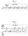
- FIG. 6 illustrates the data formats for transmissions over the downlink and uplink paths 37, 39 of the T1 facility 36.
- transmissions include a predetermined sequence of bits (referred to herein as framing bits). These framing bits provide a point of reference for determining the beginning of a frame.
- transmissions include additional framing bits for indicating the beginning of the signaling channel and one of the following: a downlink or uplink signaling message with an identifier for specifying a particular base station; or flag characters indicating the absence of signaling messages.
- the identifier specifies a base station to which the associated downlink signaling message is intended.
- the identifier specifies a base station from which the associated uplink signaling message was transmitted.
- transmissions include additional framing bits for indicating the beginning of a particular traffic channel, downlink or uplink user traffic (e.g., coded voice or data), and a header indicating a mobile-telephone.
- downlink or uplink user traffic e.g., coded voice or data
- a header indicating a mobile-telephone.
- the header indicates a mobile-telephone to which the downlink coded voice or data is intended.
- the header indicates a mobile-telephone from which the uplink coded voice or data was transmitted.
- the BSC 34 is a device for controlling the resources of the base stations 32- i and for setting up the relaying of user traffic between the base stations 32- i and a land-line network (such as a public switched telephone network connected to the BSC 34 via a mobile switching center), not shown.
- the BSC 34 includes control software executing on a processor 38 for processing and generating uplink and downlink signaling messages.
- the base stations 32- i are devices for interfacing between mobile-telephones and a land-line network.
- Each of the base stations 32- i includes a downlink circuitry 40 and an uplink circuitry 42 for processing data transmitted over the downlink or uplink signaling channels, respectively, as will be explained herein.
- FIG. 7 is a simplified schematic of the downlink circuitry 40 in accordance with one embodiment of the present invention.
- the downlink circuitry 40 includes a signal level buffer 50, a framer 52, a time slot interchanger (TSI) 54, an universal synchronous-asynchronous receiver transceiver (USART) 56, a microprocessor 58 and random access memory (RAM) 60.
- the signal level buffer 50 is connected to the downlink path 37 to reduce the load on the T1 facility 36.
- the signal level buffer 50 permits the base station to bridge or tap onto the downlink path without delaying or interrupting the bit stream being transmitted over the downlink path.
- the downlink bit stream is passed through the signal level buffer 50 to the framer 52, which is a device having functionality for detecting or finding the beginning of a frame and/or a communication channel (e.g., signaling channel or traffic channel) using the framing bits.
- the framer 52 Upon detecting the beginning of a frame or a communication channel in the downlink bit stream, the framer 52 sends an indication to the TSI 54 that the beginning of a frame or a particular communication channel has been detected.
- the TSI 54 is a device for selectively termination and repeating (or forwarding) data and is well-known in the art. When the TSI 54 receives the indication, the TSI 54 will know the next set of bits was transmitted at the beginning of the frame and/or over a particular communication channel.
- the TSI 54 is configured to pass the set of bits transmitted over the downlink signaling channel (i.e., downlink signaling channel bits) to the USART 56.
- the USART 56 is a device for examining the set of downlink signaling channel bits (or part thereof) for the presence of signaling messages, and is well-known in the art. Specifically, the USART 56 will look for the flag characters indicating the absence of signaling messages.
- the USART 56 does not detect the flag characters (e.g., 10000001), the USART passes the set of downlink signaling channel bits to the microprocessor 58 which, in turn, will store such set of bits in the RAM 60. If the USART 56 detects the flag characters, the USART 56 discards the set of downlink signaling channel bits and does not pass them to the microprocessor 58.
- the flag characters comprise a "1000001" bit sequence.
- the USART 56 will transmit an interrupt signal to the microprocessor 58 indicating that the next set of bits is the beginning of a signaling message.
- the USART 56 will transmit an interrupt signal to the microprocessor 58 indicating that the former set of bits was the end of the signaling message.
- the microprocessor 58 examines the identifier associated with the stored signaling message to determine whether the signaling message is intended for its base station. If yes, the microprocessor will process the signaling message. If no, the microprocessor discards the signaling message.
- FIG. 8 is a simplified schematic of the uplink circuitry 42 in accordance with one embodiment of the present invention.
- the uplink circuitry 42 includes signal level buffers 62, 64, a framer 66, a TSI 68, a USART 70, a microprocessor 72 and RAM 74.
- the signal level buffer 62 is connected to the uplink path 39 to reduce the load on the T1 facility 36.
- the uplink data is passed through the signal level buffer 62 to the framer 66, which searches for the beginning of a frame and/or a communication channel in the uplink bit stream.
- the framer 66 Upon detecting the beginning of a frame and/or a communication channel, the framer 66 sends an indication to the TSI 68 that the beginning of a frame and/or a communication channel has been detected.
- the TSI 68 is configured to pass the set of bits transmitted over the uplink traffic channel back into the uplink traffic channels via the signal level buffer 64, and to pass the set of bits transmitted over the signaling channel to the USART 70.
- the USART 70 will process uplink signaling channel bits in the same manner the USART 56 processes downlink signaling channel bits.
- the signaling messages passed from the USART 70 to the microprocessor 72 will be stored by the microprocessor 72 in RAM 74. Note that the signaling messages passed by the USART 70 are signaling messages generated by other base stations in the wireless communication system. In addition to these signaling messages, stored within RAM 74 may also be a signaling message generated by the base station to which the microprocessor 72 is a part (i.e., receiving or current base station).
- Signaling messages (generated by the current base station or other base stations) stored in the RAM 74 are passed back to the USART 70 on a "first-in, first-out" basis.
- the USART 70 will pass the signaling messages from the microprocessor 72 to the TSI 68. Anytime the USART 70 does not receive a signaling message from the microprocessor to pass to the TSI 68, the USART 70 will pass flag characters to the TSI 68.
- the TSI 68 will insert the bits passed from USART 70 into the uplink signaling channel via the signal level buffer 64, thus transmitting all the signaling messages to the base station controller.
- the present invention should not be limited to an apparatus and method for sharing a signaling channel.
- the present invention can also be used to share other communication channels.
- the present invention should not be limited to being used in a wireless communication system in which the base stations are connected in a daisy chain configuration to a base station via a common T1 facility.
- Other configurations, such as parallel configurations, and other transmission facilities are possible. Therefore, the spirit and scope of the present invention should not be limited to the description of the embodiments contained herein.
Abstract
Description
- The present invention relates to telecommunications system and, in particular, to wireless communications system using a common transmission line to connect a plurality of base stations to a base station controller.
- Wireless communication systems generally use transmission lines that are configured in a channelized format, such as T1 or E1 facilities, to connect a set of base stations to a base station controller (BSC). FIG. I illustrates a
wireless communication system 10 in which aBSC 12 is individually connected to base stations 14-i via respective T1 facilities 16-i, where i=1, 2,..., n. Each of the T1 facilities 16-i includes a downlink path 17-i and an uplink path 19-i, as shown in FIG. 2, for the transmission of data to and from the base stations 14-i, respectively. Each of the paths 17-i, 19-i is configured into a channelized format - that is, the paths are divided into transmission time slots. FIG. 3 illustrates a manner for channelizing the paths 17-i, 19-i. Each of the paths 17-i, 19-i is divided into frames having a framing time slot and twenty-four DS0 j time slots, where j=1, 2,..., 24 and each of the DS0 j time slots has a 64 Kbps bandwidth. Thus, thewireless communication system 10 has a 24·n number of DS0 j time slots in the downlink direction and 24·n number of DS0 j time slots in the uplink direction. - The DS0 j time slots are used to form communication channels, including a signaling channel and a plurality of traffic channels. Each communication channel includes at least one DS0 j time slot in the downlink path 17-i and the uplink path 19-i. For purposes of discussion, a DS0 j time slot shall be hereinafter deemed to refer to both a DS0 j time slot in the downlink path and a DS0 j time slot in the uplink path, unless otherwise specified.
- Each of the base stations 14-i uses x number of DS0 j time slots as a signaling channel for transmitting control information between the base station 14-i and the
BSC 12, where x≥1. Each of the base stations 14-i can support enough user traffic to consume p number of traffic channels (for transmitting the user traffic between the base station 14-i and theBSC 12 and a voice switch, not shown), wherein a traffic channel comprises y number of DS0 j time slots and y≥21. Thus, the T1 facilities 16-i should at least have a bandwidth that includes q number of DS0 j time slots, where q=y·p+x. - Generally, each of the T1 facilities 16-i has a bandwidth that includes more than q number of DS0 j time slots - that is, the user traffic supported by an individual base station (and the control information) does not consume the entire bandwidth available on a T1 facility (i.e., q<n). Thus, the base station does not use some DS0 j time slots resulting in inefficient utilization of the T1 facility.
- To more efficiently utilize T1 facilities and reduce the cost of a wireless communication system, one or more T1 facilities may be shared by a plurality of base stations. FIG. 4 illustrates a
wireless communication system 20 in which a daisy chain configuration is used to connect n number of base stations 22-i to aBSC 24 via acommon T1 facility 26. Unlike thewireless communication system 10, thewireless communication system 20 has a total of 24 number of DS0 j time slots (compared to 24·n number of DS0 j time slots in the wireless communication system 10). Like the base stations 14-i, each of the base stations 22-i has its own signaling channel comprising x number of DS0 j time slots - that is, n·x number of DS0 j time slots on theT1 facility 26 are used as signaling channels. The remaining DS0 j time slots in theT1 facility 26, i.e., m-n·x, can be used as traffic channels. The number of remaining DS0 j time slots should be at least equal to the total number of DS0 j time slots needed by the base stations 22-i to support user traffic, i.e., 24-n·x≥ y·p·n. Recall that n represents the total number of base stations, x represents the number of DS0 j time slots composing a signaling channel, y represents the number of DS0 j time slots composing a traffic channel, and p represents the number of traffic channels consumable by user traffic per base station. - In some cases, the total number of DS0 j time slots needed by the base stations to support user traffic is greater than the number of remaining DS0 j time slots. In these cases, more DS0 j time slots (or traffic channels) are required to support the user traffic. For example, suppose the
wireless communication system 20 includes five base stations (i.e., n=5), each signaling channel and traffic channel comprises one DS0 j time slot (i.e., x=1 and y=1), and the user traffic supported by each of the base stations 22-i consumes four traffic channels (i.e., p=4). If each base station 2-i has its own signaling channel (for a total of five DS0 j time slots), then there would only be nineteen DS0 j time slots available for use as traffic channels by the five base stations. Since each base station supports enough user traffic to consume four traffic channels, twenty DS0 j time slots are needed by the wireless communication system for traffic channels. Because the T1 facility has only nineteen DS0 j time slots available for use as traffic channels, the needs of thewireless communication system 20 would exceed the capacity of the T1 facility. - One way to increase the number of DS0 j time slots available for use as traffic channels is to use additional T1 facilities. Such a solution would undesirably increase the cost of the wireless communication system. Accordingly, there exists a need for increasing the number of DS0 j time slots available for use as traffic channels in a T1 facility connecting two or more base stations to a base station controller.
- The present invention provides an apparatus and a method for increasing the number of DS0 j time slots available for use as traffic channels in a T1 or E1 facility connecting two or more base stations to a base station controller by sharing a signaling channel among the base stations. The present invention is based on the concept that a single base station does not utilize the entire bandwidth of the signaling channel for the transmittal of signaling messages, i.e., control information for managing resources at one or more base stations. Better utilization of the signaling channel bandwidth can be achieved if two or more base stations can share the same signaling channel which, in turn, results in making more DS0 j time slots available for use as traffic channels. To share a signaling channel, the wireless communication system should be configured such that each of the base stations can receive its signaling over a downlink the signaling channel, and transmit its signaling messages to the base station controller over an uplink signaling channel without interfering with signaling messages transmitted by other base stations over the uplink signaling channel.
- In one embodiment, the base station controller transmits over the downlink signaling channel a downlink signaling message with an associated identifier which specifies the base station to which the signaling message is intended. Each of the base stations bridges or taps onto the transmission facility to receive the downlink signaling message and identifier. This permits downlink signaling messages and identifiers to pass transparently through the receiving base station and to other base stations in the wireless communication system. The receiving base station examines the identifier to determine whether the associated downlink signaling message is intended for that base station. If yes, the base station executes instructions contained within the downlink signaling message. Otherwise, the downlink signaling message is ignored.
- In another embodiment of the present invention, each of the base stations transmits its uplink signaling message to the base station controller without interfering (e.g., overwriting) with uplink signaling messages transmitted by other base stations. In this embodiment, the base station receives uplink signaling messages (and associated identifiers) transmitted by other base stations over the uplink signaling channel to the bas station controller. The receiving base station stores the received uplink signaling message in memory associated with that base station. Also stored within the same (or different) memory may be an uplink signaling message (and identifier) generated by the receiving base station for transmission to the base station controller. Any signaling messages stored in the memory of the receiving base station is then transmitted to the base station controller on a "first-in, first-out" basis over the uplink signaling channel. Hence, signaling messages from all base stations in the wireless communication system are assured of being transmitted to the base station controller.
- The features, aspects, and advantages of the present invention will become better understood with regard to the following description, appended claims, and accompanying drawings where:
- FIG. 1 depicts a wireless communication system in which each of a plurality of base stations has an associated T1 facility for connecting to a common base station controller;
- FIG. 2 depicts a T1 facility comprising of an uplink path and a downlink path;
- FIG. 3 depicts a manner for channelizing a T1 facility;
- FIG. 4 depicts a wireless communication system in which a "daisy chain" configuration is used to connect a plurality of base stations to a base station controller via a common T1 facility;
- FIG. 5 depicts a wireless communication system comprising a plurality of base stations connected to a base station controller via a common T1 facility in accordance with one embodiment of the present invention;
- FIG. 6 depicts data formats for transmissions over downlink and uplink paths of T1 facilities in accordance with one embodiment of the present invention; and
- FIG. 7 depicts a downlink circuitry in accordance with one embodiment of the present invention; and
- FIG. 8 depicts an uplink circuitry in accordance with one embodiment of the present invention.
-
- FIG. 5 shows a
wireless communication system 30 comprising a plurality of base stations 32-i and a base station controller (BSC) 34 used in accordance with the present invention, where i=1, 2,..., n. The base stations 32-i are connected to theBSC 34 in a daisy chain configuration using acommon T1 facility 36 configured in a channelized format. FIG. 6 illustrates the data formats for transmissions over the downlink anduplink paths T1 facility 36. In the downlink and uplink framing time slots, transmissions include a predetermined sequence of bits (referred to herein as framing bits). These framing bits provide a point of reference for determining the beginning of a frame. In the downlink and uplink signaling channel DS0 j time slots, transmissions include additional framing bits for indicating the beginning of the signaling channel and one of the following: a downlink or uplink signaling message with an identifier for specifying a particular base station; or flag characters indicating the absence of signaling messages. In the downlink signaling channel, the identifier specifies a base station to which the associated downlink signaling message is intended. In the uplink signaling channel, the identifier specifies a base station from which the associated uplink signaling message was transmitted. - Similarly, in the downlink and uplink traffic channel DS0 j time slots, transmissions include additional framing bits for indicating the beginning of a particular traffic channel, downlink or uplink user traffic (e.g., coded voice or data), and a header indicating a mobile-telephone. In the downlink traffic channel, the header indicates a mobile-telephone to which the downlink coded voice or data is intended. In the uplink traffic channel, the header indicates a mobile-telephone from which the uplink coded voice or data was transmitted.
- The
BSC 34 is a device for controlling the resources of the base stations 32-i and for setting up the relaying of user traffic between the base stations 32-i and a land-line network (such as a public switched telephone network connected to theBSC 34 via a mobile switching center), not shown. TheBSC 34 includes control software executing on a processor 38 for processing and generating uplink and downlink signaling messages. - The base stations 32-i are devices for interfacing between mobile-telephones and a land-line network. Each of the base stations 32-i includes a
downlink circuitry 40 and an uplink circuitry 42 for processing data transmitted over the downlink or uplink signaling channels, respectively, as will be explained herein. FIG. 7 is a simplified schematic of thedownlink circuitry 40 in accordance with one embodiment of the present invention. Thedownlink circuitry 40 includes asignal level buffer 50, aframer 52, a time slot interchanger (TSI) 54, an universal synchronous-asynchronous receiver transceiver (USART) 56, amicroprocessor 58 and random access memory (RAM) 60. Thesignal level buffer 50 is connected to thedownlink path 37 to reduce the load on theT1 facility 36. Thesignal level buffer 50 permits the base station to bridge or tap onto the downlink path without delaying or interrupting the bit stream being transmitted over the downlink path. The downlink bit stream is passed through thesignal level buffer 50 to theframer 52, which is a device having functionality for detecting or finding the beginning of a frame and/or a communication channel (e.g., signaling channel or traffic channel) using the framing bits. Upon detecting the beginning of a frame or a communication channel in the downlink bit stream, theframer 52 sends an indication to theTSI 54 that the beginning of a frame or a particular communication channel has been detected. - The
TSI 54 is a device for selectively termination and repeating (or forwarding) data and is well-known in the art. When theTSI 54 receives the indication, theTSI 54 will know the next set of bits was transmitted at the beginning of the frame and/or over a particular communication channel. TheTSI 54 is configured to pass the set of bits transmitted over the downlink signaling channel (i.e., downlink signaling channel bits) to theUSART 56. TheUSART 56 is a device for examining the set of downlink signaling channel bits (or part thereof) for the presence of signaling messages, and is well-known in the art. Specifically, theUSART 56 will look for the flag characters indicating the absence of signaling messages. For example, suppose the flag characters comprise a "1000001" bit sequence. If theUSART 56 does not detect the flag characters (e.g., 10000001), the USART passes the set of downlink signaling channel bits to themicroprocessor 58 which, in turn, will store such set of bits in theRAM 60. If theUSART 56 detects the flag characters, theUSART 56 discards the set of downlink signaling channel bits and does not pass them to themicroprocessor 58. - Anytime the
USART 56 detects flag characters in a set of downlink signaling channel bits and a signaling message in a next set of downlink signaling channel bits, theUSART 56 will transmit an interrupt signal to themicroprocessor 58 indicating that the next set of bits is the beginning of a signaling message. Likewise, anytime theUSART 56 detects a signaling message in a set of downlink signaling channel bits and flag characters in a next set of downlink signaling channel bits, theUSART 56 will transmit an interrupt signal to themicroprocessor 58 indicating that the former set of bits was the end of the signaling message. When a complete signaling message is in theRAM 60, themicroprocessor 58 examines the identifier associated with the stored signaling message to determine whether the signaling message is intended for its base station. If yes, the microprocessor will process the signaling message. If no, the microprocessor discards the signaling message. - FIG. 8 is a simplified schematic of the uplink circuitry 42 in accordance with one embodiment of the present invention. The uplink circuitry 42 includes signal level buffers 62, 64, a
framer 66, aTSI 68, aUSART 70, amicroprocessor 72 andRAM 74. Thesignal level buffer 62 is connected to theuplink path 39 to reduce the load on theT1 facility 36. The uplink data is passed through thesignal level buffer 62 to theframer 66, which searches for the beginning of a frame and/or a communication channel in the uplink bit stream. Upon detecting the beginning of a frame and/or a communication channel, theframer 66 sends an indication to theTSI 68 that the beginning of a frame and/or a communication channel has been detected. - The
TSI 68 is configured to pass the set of bits transmitted over the uplink traffic channel back into the uplink traffic channels via thesignal level buffer 64, and to pass the set of bits transmitted over the signaling channel to theUSART 70. TheUSART 70 will process uplink signaling channel bits in the same manner theUSART 56 processes downlink signaling channel bits. The signaling messages passed from theUSART 70 to themicroprocessor 72 will be stored by themicroprocessor 72 inRAM 74. Note that the signaling messages passed by theUSART 70 are signaling messages generated by other base stations in the wireless communication system. In addition to these signaling messages, stored withinRAM 74 may also be a signaling message generated by the base station to which themicroprocessor 72 is a part (i.e., receiving or current base station). Signaling messages (generated by the current base station or other base stations) stored in theRAM 74 are passed back to theUSART 70 on a "first-in, first-out" basis. TheUSART 70, in turn, will pass the signaling messages from themicroprocessor 72 to theTSI 68. Anytime theUSART 70 does not receive a signaling message from the microprocessor to pass to theTSI 68, theUSART 70 will pass flag characters to theTSI 68. TheTSI 68 will insert the bits passed fromUSART 70 into the uplink signaling channel via thesignal level buffer 64, thus transmitting all the signaling messages to the base station controller. - Note that the present invention should not be limited to an apparatus and method for sharing a signaling channel. The present invention can also be used to share other communication channels. Further note that the present invention should not be limited to being used in a wireless communication system in which the base stations are connected in a daisy chain configuration to a base station via a common T1 facility. Other configurations, such as parallel configurations, and other transmission facilities are possible. Therefore, the spirit and scope of the present invention should not be limited to the description of the embodiments contained herein.
Claims (10)
- A method for sharing a communication channel in a wireless communication system having a plurality of base stations connected to each other via a transmission facility, the transmission facility having a plurality of time slots, the method CHARACTERIZED BY the steps of:receiving data at a base station over the transmission facility, at least a portion of the data being received over a first communication channel having at least one time slot; andexamining at least a portion of the data received over the first communication channel to determine whether the data received over the first communication is intended for the receiving base station.
- The method of claim 1, CHARACTERIZED IN THAT the first communication channel is a signaling channel and the portion of data being received over the signaling channel includes signaling channel data, the signaling channel data having a signaling message and an identifier for specifying a particular base station to which the signaling message is intended.
- The method of claim 2 CHARACTERIZED BY the additional step of:processing the signaling message if the identifier specifies the receiving base station.
- The method of claim 2 CHARACTERIZED BY the additional step of:forwarding the signaling channel data to another base station over the signaling channel.
- The method of claim 1, CHARACTERIZED IN THAT at least another portion of the data is received over a second communication channel having at least one time slot.
- A method for sharing a communication channel in a wireless communication system having a plurality of base stations connected to each other via a transmission facility, the transmission facility having a plurality of communication channels, the method CHARACTERIZED BY the steps of:receiving at a base station a first set of bits over a communication channel;examining the first set of bits to determine whether the first set of bits includes flag characters indicating the absence of signaling messages;transmitting from the base station a second set of bits over the communication channel, the second set of bits having at least the first set of bits if the first set of bits includes the flag characters.
- The method of claim 6, CHARACTERIZED IN THAT the second set of bits includes a third set of bits belonging to the receiving base station.
- The method of claim 7, CHARACTERIZED IN THAT the third set of bits includes a signaling message.
- The method of claim 6, CHARACTERIZED IN THAT the second set of bits includes flag characters indicating the absence of the flag characters if the first set of bits does not include the flag characters.
- The method of claim 6, CHARACTERIZED IN THAT the step of examining the first set of bits includes the step of:examining a subset of the first set of bits to determine whether the subset is flag characters indicating the absence of the flag characters.
Applications Claiming Priority (2)
| Application Number | Priority Date | Filing Date | Title |
|---|---|---|---|
| US08/920,389 US6507575B1 (en) | 1997-08-29 | 1997-08-29 | Apparatus and method for sharing a signaling channel |
| US920389 | 1997-08-29 |
Publications (3)
| Publication Number | Publication Date |
|---|---|
| EP0899899A2 true EP0899899A2 (en) | 1999-03-03 |
| EP0899899A3 EP0899899A3 (en) | 1999-05-19 |
| EP0899899B1 EP0899899B1 (en) | 2001-09-19 |
Family
ID=25443651
Family Applications (1)
| Application Number | Title | Priority Date | Filing Date |
|---|---|---|---|
| EP98306557A Expired - Lifetime EP0899899B1 (en) | 1997-08-29 | 1998-08-18 | An apparatus and method for sharing a signaling channel |
Country Status (9)
| Country | Link |
|---|---|
| US (1) | US6507575B1 (en) |
| EP (1) | EP0899899B1 (en) |
| JP (1) | JPH11150757A (en) |
| KR (1) | KR19990023998A (en) |
| CN (1) | CN1215964A (en) |
| BR (1) | BR9803193A (en) |
| CA (1) | CA2244383C (en) |
| DE (1) | DE69801728T2 (en) |
| TW (1) | TW393845B (en) |
Cited By (6)
| Publication number | Priority date | Publication date | Assignee | Title |
|---|---|---|---|---|
| WO2000070890A1 (en) * | 1999-05-17 | 2000-11-23 | Nokia Networks Oy | Resource allocation method |
| WO2001043470A1 (en) * | 1999-12-09 | 2001-06-14 | Telia Ab | Procedure and arrangement to make redundancy for a radio communication system |
| WO2003039174A1 (en) * | 2001-10-29 | 2003-05-08 | Ericsson, Inc. | 2 different carrier protocols at radio base station nodes for respectively data communication to a mobile switching center and other radio base station station nodes |
| US7061884B2 (en) | 2001-10-29 | 2006-06-13 | Ericsson Inc. | Methods and systems for communicating data at radio base station nodes that provide efficient allocation of control timeslots |
| EP1791380A1 (en) * | 2004-09-10 | 2007-05-30 | Mitsubishi Electric Corporation | Wireless access network and handover method |
| EP2348787A1 (en) * | 2010-01-22 | 2011-07-27 | Alcatel Lucent | Distributing system for the communication between distributed base stations, and distributing unit therefor |
Families Citing this family (5)
| Publication number | Priority date | Publication date | Assignee | Title |
|---|---|---|---|---|
| US6560652B1 (en) * | 1998-11-20 | 2003-05-06 | Legerity, Inc. | Method and apparatus for accessing variable sized blocks of data |
| KR100408822B1 (en) * | 2001-05-09 | 2003-12-06 | 에스케이 텔레콤주식회사 | Apparatus for handling the maintenance of a mobile telecommunication terminal and method for providing a data service therewith |
| US8908650B2 (en) * | 2004-10-12 | 2014-12-09 | Telefonaktiebolaget Lm Ericsson (Publ) | Interface, apparatus, and method for communication between a radio equipment control node and one or more remote radio equipment nodes |
| US9225488B2 (en) * | 2005-10-27 | 2015-12-29 | Qualcomm Incorporated | Shared signaling channel |
| JP2011114689A (en) * | 2009-11-27 | 2011-06-09 | Fujitsu Ltd | Radio base station apparatus |
Citations (3)
| Publication number | Priority date | Publication date | Assignee | Title |
|---|---|---|---|---|
| US5313461A (en) * | 1989-10-19 | 1994-05-17 | Inventahl Ab | Method and device in a digital communication network |
| US5572546A (en) * | 1994-12-22 | 1996-11-05 | Motorola, Inc. | Data communications system with multilink protocol |
| WO1998037669A1 (en) * | 1997-02-25 | 1998-08-27 | Telefonaktiebolaget Lm Ericsson (Publ) | Multiple access communication network with combined contention and reservation mode access |
Family Cites Families (11)
| Publication number | Priority date | Publication date | Assignee | Title |
|---|---|---|---|---|
| US4607364A (en) * | 1983-11-08 | 1986-08-19 | Jeffrey Neumann | Multimode data communication system |
| JPS6387838A (en) * | 1986-09-30 | 1988-04-19 | Nec Corp | Supervisory system for communication network |
| JPH0234059A (en) * | 1988-07-25 | 1990-02-05 | Mitsubishi Electric Corp | Processing system for node equipment |
| US5507006A (en) * | 1989-07-31 | 1996-04-09 | Knight; Phillip | Cellular radio system for transmission of signalling information on the basis of its urgency or during temporary cessation of communication |
| FI92786C (en) * | 1993-03-30 | 1994-12-27 | Nokia Telecommunications Oy | Procedure for searching signaling channel in a radio system |
| FI108100B (en) * | 1993-06-23 | 2001-11-15 | Nokia Networks Oy | Communication method and communication system in a cellular radio network |
| AUPM593694A0 (en) | 1994-05-27 | 1994-06-23 | Curtin University Of Technology | Underground microcellular communications network |
| US5648958A (en) * | 1995-04-05 | 1997-07-15 | Gte Laboratories Incorporated | System and method for controlling access to a shared channel for cell transmission in shared media networks |
| US5699356A (en) * | 1995-07-17 | 1997-12-16 | Mci Communication | System and method for personal communication system dynamic channel allocation |
| US5960362A (en) * | 1996-06-24 | 1999-09-28 | Qualcomm Incorporated | Method and apparatus for access regulation and system protection of a dispatch system |
| US5748104A (en) * | 1996-07-11 | 1998-05-05 | Qualcomm Incorporated | Wireless remote telemetry system |
-
1997
- 1997-08-29 US US08/920,389 patent/US6507575B1/en not_active Expired - Fee Related
-
1998
- 1998-07-20 TW TW087111792A patent/TW393845B/en not_active IP Right Cessation
- 1998-07-27 CA CA002244383A patent/CA2244383C/en not_active Expired - Fee Related
- 1998-08-18 EP EP98306557A patent/EP0899899B1/en not_active Expired - Lifetime
- 1998-08-18 DE DE69801728T patent/DE69801728T2/en not_active Expired - Fee Related
- 1998-08-19 BR BR9803193-7A patent/BR9803193A/en not_active Application Discontinuation
- 1998-08-28 JP JP10242409A patent/JPH11150757A/en active Pending
- 1998-08-28 KR KR1019980035195A patent/KR19990023998A/en not_active Application Discontinuation
- 1998-08-28 CN CN98118507A patent/CN1215964A/en active Pending
Patent Citations (3)
| Publication number | Priority date | Publication date | Assignee | Title |
|---|---|---|---|---|
| US5313461A (en) * | 1989-10-19 | 1994-05-17 | Inventahl Ab | Method and device in a digital communication network |
| US5572546A (en) * | 1994-12-22 | 1996-11-05 | Motorola, Inc. | Data communications system with multilink protocol |
| WO1998037669A1 (en) * | 1997-02-25 | 1998-08-27 | Telefonaktiebolaget Lm Ericsson (Publ) | Multiple access communication network with combined contention and reservation mode access |
Non-Patent Citations (1)
| Title |
|---|
| WHITEHEAD J F: "DISTRIBUTED PACKET DYNAMIC RESOURCE ALLOCATION (DRA) FOR WIRELESS NETWORKS" 1996 IEEE 46TH. VEHICULAR TECHNOLOGY CONFERENCE, MOBILE TECHNOLOGY FOR THE HUMAN RACE ATLANTA, APR. 28 - MAY 1, 1996, vol. 1, no. CONF. 46, 28 April 1996, pages 111-115, XP000594286 INSTITUTE OF ELECTRICAL AND ELECTRONICS ENGINEERS * |
Cited By (9)
| Publication number | Priority date | Publication date | Assignee | Title |
|---|---|---|---|---|
| WO2000070890A1 (en) * | 1999-05-17 | 2000-11-23 | Nokia Networks Oy | Resource allocation method |
| WO2001043470A1 (en) * | 1999-12-09 | 2001-06-14 | Telia Ab | Procedure and arrangement to make redundancy for a radio communication system |
| WO2003039174A1 (en) * | 2001-10-29 | 2003-05-08 | Ericsson, Inc. | 2 different carrier protocols at radio base station nodes for respectively data communication to a mobile switching center and other radio base station station nodes |
| US7061884B2 (en) | 2001-10-29 | 2006-06-13 | Ericsson Inc. | Methods and systems for communicating data at radio base station nodes that provide efficient allocation of control timeslots |
| US7181242B2 (en) | 2001-10-29 | 2007-02-20 | Ericsson Inc. | Systems and methods for communicating data at radio base station nodes |
| EP1791380A1 (en) * | 2004-09-10 | 2007-05-30 | Mitsubishi Electric Corporation | Wireless access network and handover method |
| EP1791380A4 (en) * | 2004-09-10 | 2009-03-18 | Mitsubishi Electric Corp | Wireless access network and handover method |
| US8089932B2 (en) | 2004-09-10 | 2012-01-03 | Mitsubishi Electric Corporation | Handover method in a wireless access network |
| EP2348787A1 (en) * | 2010-01-22 | 2011-07-27 | Alcatel Lucent | Distributing system for the communication between distributed base stations, and distributing unit therefor |
Also Published As
| Publication number | Publication date |
|---|---|
| CA2244383C (en) | 2003-02-18 |
| BR9803193A (en) | 1999-10-19 |
| DE69801728T2 (en) | 2002-07-11 |
| US6507575B1 (en) | 2003-01-14 |
| DE69801728D1 (en) | 2001-10-25 |
| TW393845B (en) | 2000-06-11 |
| CN1215964A (en) | 1999-05-05 |
| JPH11150757A (en) | 1999-06-02 |
| EP0899899B1 (en) | 2001-09-19 |
| KR19990023998A (en) | 1999-03-25 |
| CA2244383A1 (en) | 1999-02-28 |
| EP0899899A3 (en) | 1999-05-19 |
Similar Documents
| Publication | Publication Date | Title |
|---|---|---|
| US7336630B2 (en) | Simultaneous transmission of speech and data on a mobile communications system | |
| US6941132B2 (en) | Transport of radio network-originated control information | |
| US5745487A (en) | Communication apparatus for transmitting/receiving different types of data in one TDM slot | |
| US20180192336A1 (en) | Radio access network control method and radio access network | |
| US6125110A (en) | Method and system for determining a packet transmission order | |
| US6205125B1 (en) | Method and system for determining an estimate of a transmission time of a packet | |
| US6925072B1 (en) | System and method for transmitting control information between a control unit and at least one sub-unit | |
| JPH07212401A (en) | Telephone network, communication method and communication system | |
| KR100415115B1 (en) | Data congestion notifying method and apparatus in communication system | |
| EP0899899B1 (en) | An apparatus and method for sharing a signaling channel | |
| JP3003714B2 (en) | Mobile communication termination control method | |
| JP3417097B2 (en) | Data transmission method for digital cordless system subscribers | |
| MXPA98006757A (en) | An apparatus and method for sharing a signal channel | |
| US20040047326A1 (en) | Employment of one traffic block of one code division multiple access traffic channel to communicate respective portions of communications between communication components | |
| JP3321360B2 (en) | Mobile communication system | |
| JPS6113843A (en) | Hybrid exchange system | |
| JP3361933B2 (en) | Line call connection control system | |
| JP2022026388A (en) | Communication device and control method thereof | |
| JP2905136B2 (en) | Signal transmission method and base station device | |
| JP2000209658A (en) | Radio data communication system | |
| JPH04108289A (en) | Digital communication control unit | |
| KR20010088114A (en) | Mux capable of dispersion transmission and priority transmission in imt-2000 base-station controller and control method thereof | |
| JPH04264853A (en) | Data communication system | |
| JPH08331639A (en) | Communication system | |
| KR19990031552A (en) | Receiving rate increase method in call processing of high speed paging system |
Legal Events
| Date | Code | Title | Description |
|---|---|---|---|
| PUAI | Public reference made under article 153(3) epc to a published international application that has entered the european phase |
Free format text: ORIGINAL CODE: 0009012 |
|
| 17P | Request for examination filed |
Effective date: 19980828 |
|
| AK | Designated contracting states |
Kind code of ref document: A2 Designated state(s): DE FI FR GB SE |
|
| AX | Request for extension of the european patent |
Free format text: AL;LT;LV;MK;RO;SI |
|
| PUAL | Search report despatched |
Free format text: ORIGINAL CODE: 0009013 |
|
| AK | Designated contracting states |
Kind code of ref document: A3 Designated state(s): AT BE CH CY DE DK ES FI FR GB GR IE IT LI LU MC NL PT SE |
|
| AX | Request for extension of the european patent |
Free format text: AL;LT;LV;MK;RO;SI |
|
| 17Q | First examination report despatched |
Effective date: 19990716 |
|
| AKX | Designation fees paid |
Free format text: DE FI FR GB SE |
|
| GRAG | Despatch of communication of intention to grant |
Free format text: ORIGINAL CODE: EPIDOS AGRA |
|
| GRAG | Despatch of communication of intention to grant |
Free format text: ORIGINAL CODE: EPIDOS AGRA |
|
| GRAG | Despatch of communication of intention to grant |
Free format text: ORIGINAL CODE: EPIDOS AGRA |
|
| GRAH | Despatch of communication of intention to grant a patent |
Free format text: ORIGINAL CODE: EPIDOS IGRA |
|
| GRAG | Despatch of communication of intention to grant |
Free format text: ORIGINAL CODE: EPIDOS AGRA |
|
| GRAH | Despatch of communication of intention to grant a patent |
Free format text: ORIGINAL CODE: EPIDOS IGRA |
|
| GRAH | Despatch of communication of intention to grant a patent |
Free format text: ORIGINAL CODE: EPIDOS IGRA |
|
| GRAA | (expected) grant |
Free format text: ORIGINAL CODE: 0009210 |
|
| AK | Designated contracting states |
Kind code of ref document: B1 Designated state(s): DE FI FR GB SE |
|
| REF | Corresponds to: |
Ref document number: 69801728 Country of ref document: DE Date of ref document: 20011025 |
|
| REG | Reference to a national code |
Ref country code: GB Ref legal event code: IF02 |
|
| ET | Fr: translation filed | ||
| PLBE | No opposition filed within time limit |
Free format text: ORIGINAL CODE: 0009261 |
|
| STAA | Information on the status of an ep patent application or granted ep patent |
Free format text: STATUS: NO OPPOSITION FILED WITHIN TIME LIMIT |
|
| 26N | No opposition filed | ||
| PGFP | Annual fee paid to national office [announced via postgrant information from national office to epo] |
Ref country code: DE Payment date: 20070822 Year of fee payment: 10 |
|
| PGFP | Annual fee paid to national office [announced via postgrant information from national office to epo] |
Ref country code: FI Payment date: 20070816 Year of fee payment: 10 |
|
| PGFP | Annual fee paid to national office [announced via postgrant information from national office to epo] |
Ref country code: GB Payment date: 20070823 Year of fee payment: 10 |
|
| PGFP | Annual fee paid to national office [announced via postgrant information from national office to epo] |
Ref country code: SE Payment date: 20070815 Year of fee payment: 10 |
|
| PGFP | Annual fee paid to national office [announced via postgrant information from national office to epo] |
Ref country code: FR Payment date: 20070823 Year of fee payment: 10 |
|
| EUG | Se: european patent has lapsed | ||
| GBPC | Gb: european patent ceased through non-payment of renewal fee |
Effective date: 20080818 |
|
| PG25 | Lapsed in a contracting state [announced via postgrant information from national office to epo] |
Ref country code: FI Free format text: LAPSE BECAUSE OF NON-PAYMENT OF DUE FEES Effective date: 20080818 |
|
| REG | Reference to a national code |
Ref country code: FR Ref legal event code: ST Effective date: 20090430 |
|
| PG25 | Lapsed in a contracting state [announced via postgrant information from national office to epo] |
Ref country code: FR Free format text: LAPSE BECAUSE OF NON-PAYMENT OF DUE FEES Effective date: 20080901 Ref country code: DE Free format text: LAPSE BECAUSE OF NON-PAYMENT OF DUE FEES Effective date: 20090303 |
|
| PG25 | Lapsed in a contracting state [announced via postgrant information from national office to epo] |
Ref country code: GB Free format text: LAPSE BECAUSE OF NON-PAYMENT OF DUE FEES Effective date: 20080818 |
|
| PG25 | Lapsed in a contracting state [announced via postgrant information from national office to epo] |
Ref country code: SE Free format text: LAPSE BECAUSE OF NON-PAYMENT OF DUE FEES Effective date: 20080819 |