EP0897031A2 - Automatic apparatus for dyeing textile materials - Google Patents
Automatic apparatus for dyeing textile materials Download PDFInfo
- Publication number
- EP0897031A2 EP0897031A2 EP98830404A EP98830404A EP0897031A2 EP 0897031 A2 EP0897031 A2 EP 0897031A2 EP 98830404 A EP98830404 A EP 98830404A EP 98830404 A EP98830404 A EP 98830404A EP 0897031 A2 EP0897031 A2 EP 0897031A2
- Authority
- EP
- European Patent Office
- Prior art keywords
- dyeing
- baskets
- station
- chambers
- rod
- Prior art date
- Legal status (The legal status is an assumption and is not a legal conclusion. Google has not performed a legal analysis and makes no representation as to the accuracy of the status listed.)
- Granted
Links
- 238000004043 dyeing Methods 0.000 title claims abstract description 54
- 239000000463 material Substances 0.000 title claims abstract description 23
- 239000004753 textile Substances 0.000 title claims abstract description 12
- 239000007788 liquid Substances 0.000 claims description 11
- 238000003756 stirring Methods 0.000 claims description 10
- 238000003860 storage Methods 0.000 claims description 2
- 239000000975 dye Substances 0.000 description 4
- 238000000034 method Methods 0.000 description 4
- 238000004140 cleaning Methods 0.000 description 3
- 238000002360 preparation method Methods 0.000 description 3
- 238000012795 verification Methods 0.000 description 3
- XLYOFNOQVPJJNP-UHFFFAOYSA-N water Substances O XLYOFNOQVPJJNP-UHFFFAOYSA-N 0.000 description 3
- 239000004744 fabric Substances 0.000 description 2
- 238000009472 formulation Methods 0.000 description 2
- 239000000203 mixture Substances 0.000 description 2
- 238000010276 construction Methods 0.000 description 1
- 230000001934 delay Effects 0.000 description 1
- 230000001419 dependent effect Effects 0.000 description 1
- 238000009776 industrial production Methods 0.000 description 1
- 238000009533 lab test Methods 0.000 description 1
- 238000004519 manufacturing process Methods 0.000 description 1
- 230000003449 preventive effect Effects 0.000 description 1
- 230000002035 prolonged effect Effects 0.000 description 1
- 238000005406 washing Methods 0.000 description 1
Images


Classifications
-
- D—TEXTILES; PAPER
- D06—TREATMENT OF TEXTILES OR THE LIKE; LAUNDERING; FLEXIBLE MATERIALS NOT OTHERWISE PROVIDED FOR
- D06B—TREATING TEXTILE MATERIALS USING LIQUIDS, GASES OR VAPOURS
- D06B5/00—Forcing liquids, gases or vapours through textile materials to effect treatment, e.g. washing, dyeing, bleaching, sizing impregnating
- D06B5/12—Forcing liquids, gases or vapours through textile materials to effect treatment, e.g. washing, dyeing, bleaching, sizing impregnating through materials of definite length
-
- D—TEXTILES; PAPER
- D06—TREATMENT OF TEXTILES OR THE LIKE; LAUNDERING; FLEXIBLE MATERIALS NOT OTHERWISE PROVIDED FOR
- D06B—TREATING TEXTILE MATERIALS USING LIQUIDS, GASES OR VAPOURS
- D06B23/00—Component parts, details, or accessories of apparatus or machines, specially adapted for the treating of textile materials, not restricted to a particular kind of apparatus, provided for in groups D06B1/00 - D06B21/00
- D06B23/10—Devices for dyeing samples
-
- D—TEXTILES; PAPER
- D06—TREATMENT OF TEXTILES OR THE LIKE; LAUNDERING; FLEXIBLE MATERIALS NOT OTHERWISE PROVIDED FOR
- D06B—TREATING TEXTILE MATERIALS USING LIQUIDS, GASES OR VAPOURS
- D06B23/00—Component parts, details, or accessories of apparatus or machines, specially adapted for the treating of textile materials, not restricted to a particular kind of apparatus, provided for in groups D06B1/00 - D06B21/00
- D06B23/20—Arrangements of apparatus for treating processing-liquids, -gases or -vapours, e.g. purification, filtration or distillation
- D06B23/205—Arrangements of apparatus for treating processing-liquids, -gases or -vapours, e.g. purification, filtration or distillation for adding or mixing constituents of the treating material
Definitions
- Each of said dyeing units (4) comprises means for vertically reciprocating a basket (6) inside the dyeing chamber (40), the materials to be treated being introduced into the basket (6) by means of an actuator cylinder (43) having vertical axis and whose rod (42) is removably connected to the upper portion of the basket (6).
- the upper side of the basket (6) may be advantageously provided with an appendix (5) intended to come in contact with the corresponding cavity (50) of a flange (55) fixed to the lower end of the rod (42) of cylinder (43).
- each basket (6) will result easily and rapidly connectable with a relevant stirring cylinder (43), with no need for screws, bolts or similar fastening elements, the connection being possibly made either manually or automatically as described later on.
Landscapes
- Engineering & Computer Science (AREA)
- Textile Engineering (AREA)
- Chemical & Material Sciences (AREA)
- Materials Engineering (AREA)
- Treatment Of Fiber Materials (AREA)
Abstract
Description
- The present invention refers to an automatic apparatus for dyeing textile materials, especially for laboratory use.
- It is known, in the dyeing of textile materials, that the materials fibres must be subjected to the action of suitable dyes diluted in a dyeing bath at a temperature and for a time to be preset according to the nature of the same fibres and the type of dyes used.
- One of the problems mostly felt in this industrial sector is the repeatability of the dyeing processes in relation to laboratory tests which are carried out for the preparation and verification of the formulations or "recipes". The dyeing performed during the industrial production stage, without a proper preventive laboratory check, may actually imply the need of correcting the formulation of the bath intended to feed the dyeing machines, which brings about extra costs, production delays, possible unevenness of the bath and consequent lower quality of the finished product.
- The main object of the present invention is to provide an automatic apparatus, especially for laboratory use, for the preparation and verification of the recipes, which is able to facilitate the standardization of the dyeing processes, to increase their reliability to a significant degree and simulate as accurately as possible the operating conditions of the dyeing process performed by means of industrial machines.
- This result has been achieved, according to the invention, by providing an apparatus having the features indicated in the characterizing part of
claim 1. Further characteristics being set forth in the dependent claims. - An apparatus according to the present invention is relatively simple to make, cost-effective and reliable even after a prolonged service life. Besides, it makes it possible to fully automate the preparation and verification of the recipes on samples of textile materials and to achieve the highest degree of repeatability of the experimental dyeing processes so as to ensure the most correct, efficient and uniform industrial dyeing of the same materials. This also allows reducing the running costs of the dyeing plants.
- These and other advantages and characteristics of the invention will be best understood by anyone skilled in the art from a reading of the following description in conjunction with the attached drawings given as a practical exemplification of the invention, but not to be considered in a limitative sense, wherein:
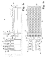
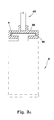
- Figs. 1A and 1B show schematically a side view and a plan view of an apparatus according to the invention;
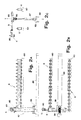
- Figs. 2A-2C show schematically the means for moving the materials-holding baskets between the dyeing device and the baskets-storing station, in which said baskets are in a condition ready for their removal from, respectively, delivery to the dyeing device;
- Figs. 2D-2F show schematically the means for moving the materials-holding baskets between the dyeing device and the baskets-storing station, in which said baskets are in a condition ready for their removal from, respectively, delivery to the support of the storing station;
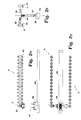
- Figs. 2G, 2H and 2L are respectively an elevation view, a plan view and side view of the station with the dyeing units, which show the means for the removal and storage of the baskets holding the materials to be treated;
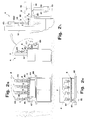
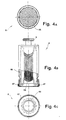
- Figs. 3A and 3B show in detail the connection between the metering device and the dyeing device, with a basket outside, respectively, inside the container holding the dyeing solution;
- Fig. 3C shows in detail the connection between the basket and the respective stirring cylinder within a dyeing unit;
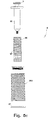
- Figs. 4A-4C shows a plan view, a longitudinal view partly in section and a bottom view of a basket for textile materials in form of hanks of yarn;
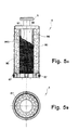
- Figs. 5A-5C show a view in longitudinal section view, a bottom view and an exploded view of a basket for textile materials in form of reels of yarn, fabrics, and the like.
- Reduced to its basic structure, and reference being made to the figures of the attached drawings, an apparatus according to the invention comprises:
- a first station (D) for storing a plurality of vessels (1) holding a plurality of dyeing solutions;
- means (2), located in correspondence of said first station (D), for the removal of the solutions from the vessels (1) in a predeterined amount and according to a programmed sequence of removal: said means (2) also providing for drawing the thus removed liquid dyes into stand-by containers (3) located downstream of the first station (D);
- means, in a second station (T) located downstream of the first one (D), with a plurality of dyeing units (4) each of which is connected to a corresponding container (3) of the set of dyes, that is, the whole of containers (3) in which the solutions removed from the vessels (1) located in the first station (D) are stored.
- As illustrated in the Figs. 1A and 1B of the attached drawings, the vessels (1) of the first station (D) can be positioned over a horizontal plane (10) on which a carriage (11) is mounted movable along the longitudinal axis of the plane (10), that is, on side straight guides (111) of the latter, under control of an electric motor (110) and with a cross-piece (12) oriented transversally to said axis, the means (2) being mounted on the cross-piece (12) of said carriage (11) for the removal of solutions from the vessels (1). The said means for the removal of the solutions are of a type comprising a pipette movable from and to the vessels (1). The construction and operation of the pipette are known to those skilled in the art and, therefore, will not be described herein in further details. For the removal of the solutions from the preselected vessels (1), the pipette (2) is moved by the carriage (11) to result in correspondence of said vessels, with the aid of a positioning system which comprises, for example, a plurality of encoders associated, respectively, to the motor (110), to a motor (112) which drives into motion the pipette (2) along the cross-piece (12) of carriage (11) and to a third motor, not shown, for moving the pipette (2) vertically. The pipette (2) results thus movable in the three spatial orthogonal directions between the station (D), the containers (3) downstream of the platform (10) and a washing station, not shown in the figures of the attached drawings, in which provision is made for at least a vessel for holding water or other liquid for cleaning the pipette (2).
- Each of the containers (3) downstream of the platform (10) is advantageously connected to the respective dyeing unit (4) via a corresponding conduit (34) through which the dyeing solution is transferred from the container (3) to the dyeing chamber (40) corresponding to the unit (4). The transfer is assisted by the admission of compressed air into the container (3) being used each time. The compressed air is introduced into the container (3) after closing a tight seal cover (30) located above and operable by an actuator (31) mounted on the fixed structure (300) which supports the containers (3), said actuator acting on an arm (310) which connects the rod thereof to the cover (30), said arm being connected to the same container (3) by a hinge member (311) having horizontal axis. Two holes formed in the cover (30) of the container (3) allow the positioning of a flexible conduit (33) for the admission of compressed air, and of a flexible conduit (330) for the admission of water or other cleaning liquid into the container (3).
- Each of said dyeing units (4) comprises means for vertically reciprocating a basket (6) inside the dyeing chamber (40), the materials to be treated being introduced into the basket (6) by means of an actuator cylinder (43) having vertical axis and whose rod (42) is removably connected to the upper portion of the basket (6). To this end, the upper side of the basket (6) may be advantageously provided with an appendix (5) intended to come in contact with the corresponding cavity (50) of a flange (55) fixed to the lower end of the rod (42) of cylinder (43). In this way, each basket (6) will result easily and rapidly connectable with a relevant stirring cylinder (43), with no need for screws, bolts or similar fastening elements, the connection being possibly made either manually or automatically as described later on.
- Each stirring cylinder (43) is suitably mounted on a support (53) moving onto a vertical straight guide (530) under control of an operating cylinder (500), so as to allow the positioning thereof at such a height that the corresponding basket (6) will result outside the dyeing chamber (40), as illustrated in Fig. 3A and, respectively, at a height allowing the same basket (6) to dip into the dyeing liquid of the chamber (40), as illustrated in Fig. 3B.
Also fixed to the said support (53), at a position below the fastening point of the stirring cylinder (43), is a body (56) which is provided with an underlying annular gasket acting as a tight-seal element for the corresponding dyeing chamber (40) when the basket (6) is dipped into the bath of the latter, the said body (56) being provided with a through hole and central gasket to allow the rod of the stirring cylinder (43) to move therethrough (see Fig. 3B). - Provided in a position below each one of said dyeing chambers (40) is a conduit (7) for the evacuation of the bath. Indicated by numeral (57) of Figs. 3A and 3B is a fixed structure to which the cylinder (500) and the straight guide (530) are fastened.
- As far as the means for the automatic positioning of the baskets (6) in correspondence of the dyeing units (4) are concerned, they comprise, according to a feasible embodiment, a horizontal arm (8) able to be moved horizontally, vertically and to be rotated about a vertical axis (v-v), said arm being provided, in correspondence of a free end thereof, with clamp means (80) whose jaws are intended to clamp on the external side wall of the baskets (6) upon the removal and the handling thereof, and to open up for their release.
- As schematically illustrated in Figs. 2A-2L of the attached drawings, the said arm (8) is formed by the rod of a pneumatic cylinder (85) having horizontal axis and mounted on a support (86) which is in turn supported by the rod of an underlying pneumatic cylinder (87) having vertical axis. The said support (86) is rotatively anchored to the rod of the vertical cylinder (87) and associated to a relevant driving member not shown in the figures of the attached drawings.
- Moreover, advantageously, the vertical cylinder (87) of the means for positioning the baskets (6) in correspondence of the units (4) is mounted on a motor-driven carriage (88) sliding under control onto a horizontal guide (89) located in proximity of the units (4) and developing parallel to them. Owing to the thus ensured handling capability of the arm (8), it is possible to pick up the baskets (6) from one or more shelves (60) on which they are positioned awaiting to reach the destination units (4), to deliver them to the respective units (4) and to remove them therefrom at the end of the cycle for dyeing the materials held therein and lying them back in the respective initial positions.
- In case only one shelf (60) is used for the baskets (6), there is no need of rotating the arm (8) and, accordingly, the horizontal cylinder (85) may be fixed to the vertical cylinder (87) without the connection member (86) being associated to any driving member.
The baskets (6) may hold textile materials in hanks of yarn, as illustrated in Figs. 4A-4C, where (65) indicates a hank of yarn wound up on a supporting core (66) able to be positioned within the cavity of the basket (6) whose upper and lower sides are provided with holes (68) for the circulation of the bath through the fibres of the yarn (65) when the basket (6) is driven by the respective stirring cylinder (43), an annular gasket (67) being associated to said lower side to ensure a tight seal against the inner wall of the dyeing chamber (40) to which the basket (6) is to be moved. - The baskets (6) may also contain textile materials (90) in different form, as illustrated in Fig. 5A, or in another form. The baskets (6) intended for textile materials in form of reels of yarn, fabrics and the like, have a central vertical core (95) with frusto-conical end, around which core are located a first and a second cylindrical grids (96, 960) of different diameter, coaxial to each other and with a close-mesh net (97) placed against the grid (96) of minor diameter (see Figs. 5A-5C). The upper and lower sides of the basket (6) are suitably drilled and the lower side is provided with an annular gasket (67) likewise the previous case. The net (97) prevents the material under treatment from flowing through the holes of the first grid (96) which, in cooperation with the central core (95), delimits a chamber of annular cross-section through which the liquid of the dyeing bath can freely circulate for a more uniform and efficient dyeing of the material under treatment.
- The operation of the above described apparatus is as follows.
According to the preset work program, the pipette (2) draws the liquids, in preset sequence and doses, from the vessels (1) located on the platform (10) into the respective containers (3). Firstly, for the transfer of the liquids from the containers (3) to the target chambers (40), the covers (30) are made to rotate in a direction which aloows closing the containers (3) and, afterwards, compressed air is drawn into the same containers to force the liquids therein to flow through the respective conduits (34). The water for cleaning the containers (3) is likewise transferred to the respective dyeing chambers (40) in a quantity measured by a volumetric meter until the preset volume of the bath inside the chambers (40) is reached. At the same time, or subsequently as well, the arm (8) with clamps (80) provides for picking up the baskets (6) loaded with material to be treated, in a sequence preset by the program, to hand them over to the respective stirring cylinder (43) disposed so as to have the baskets (6) lifted up, that is, moved outside the chambers (40) wherein the liquid is admitted from the containers (3). Each basket (6) thus positioned is then dipped down into the respective dyeing chamber (40) by the cylinder (500) which commands the lowering of the structure (53) sipporting the respective stirring cylinder (43), thereby operating, at the same time, the closing of the chamber (40) by means of the element (56). At this point, the stirring cylinder (43) of each basket (6) thus positioned is operated for a time preset according to the specific dyeing cycle to be performed, thereby circulating the bath across the fibres of the textile material from the inside to the outside of basket (6); each basket (6) acting as the plunger of a pump. At the end of this cycle, each basket is withdrawn from the respective dyeing chamber (40) under control of the respective cylinder (500), and picked up by the arm (8) that puts it down in a stand-by position outside the dyeing station (T) . It will be appreciated that in the course of the dyeing of materials held in each basket (6), the drawing and the metering of the liquids held in the vessels (1) can be operated at any time, as the cycles for dyeing, drawing and metering are independent from each other.
For the control of the operating stages above described, electronic programmable means are used whose modes of operation are already known to those skilled in the industrial automation.
Claims (7)
- Apparatus for dyeing textile materials comprising means within a first station (D) for the drawing and metering of dyeing solutions and for the admission thereof into corresponding containers (3) intended to feed one or more chambers (40) for dyeing the materials disposed inside storage baskets (6), said baskets (6) being able to be connected to corresponding stirrer means (43) located in correspondence of the chambers (40) in a second station (T), characterized in that said containers (3) are hydraulically connected with the respective materials-dyeing chambers (40) and that said baskets (6) can be connected in a stable but removable way to the stirrer means (43).
- Apparatus according to claim 1, characterized in that each of said containers (3) is associated to means for feeding compressed air to facilitate the transfer of dyeing liquids to the respective dyeing chambers (40) of the second station (T).
- Apparatus according to claim 1, characterized in that said stirrer means (43) are made up of cylinders with horizontal axis, located above the dyeing chambers (40) in said second station (D), and the upper part of each basket (6) is removably connected to the lower end of the rod of each of said cylinders.
- Apparatus according to claims 1 and 3, characterized in that the upper side of each basket (6) is provided with an appendix (5) intended to come in contact with the corresponding cavity (50) of a flange (55) fixed to the lower end of the rod (42) of each stirring cylinder (43).
- Apparatus according to claim 1, characterized in that it comprises means for the automatic positioning of the baskets (6) in correspondence of the dyeing units (4) of the second station (T), with an arm (8) to the free end of which clamp means (80) are secured, the clamp having jaws intended to clamp on the external side wall of the baskets (6) upon the removal and the handling thereof, and to open up for their release: said arm (8) being movable at least horizontally from and to the stirrer means (43) and parallel thereto.
- Apparatus according to claims 1 and 5, characterized in that said arm (8) is formed by the rod of a pneumatic cylinder (85) having horizontal axis and mounted on a support (86) which is in turn supported by the rod of an underlying pneumatic cylinder having vertical axis (87): said vertical cylinder (87) being mounted on a motor-driven carriage (88) sliding, under control, onto a horizontal guide (89) located in proximity of the units (4) and developing parallel to them.
- Apparatus according to claims 1 and 3, characterized in that said support (86) is rotatively anchored to the rod of the vertical cylinder (87) and associated to a relevant driving member.
Applications Claiming Priority (2)
| Application Number | Priority Date | Filing Date | Title |
|---|---|---|---|
| ITFI970199 | 1997-08-14 | ||
| IT97FI000199A IT1295153B1 (en) | 1997-08-14 | 1997-08-14 | AUTOMATIC DYEING EQUIPMENT FOR TEXTILE MATERIALS |
Publications (3)
| Publication Number | Publication Date |
|---|---|
| EP0897031A2 true EP0897031A2 (en) | 1999-02-17 |
| EP0897031A3 EP0897031A3 (en) | 2000-05-03 |
| EP0897031B1 EP0897031B1 (en) | 2003-01-22 |
Family
ID=11352235
Family Applications (1)
| Application Number | Title | Priority Date | Filing Date |
|---|---|---|---|
| EP98830404A Expired - Lifetime EP0897031B1 (en) | 1997-08-14 | 1998-07-02 | Automatic apparatus for dyeing textile materials |
Country Status (5)
| Country | Link |
|---|---|
| US (1) | US6094947A (en) |
| EP (1) | EP0897031B1 (en) |
| AT (1) | ATE231574T1 (en) |
| DE (1) | DE69810857D1 (en) |
| IT (1) | IT1295153B1 (en) |
Cited By (9)
| Publication number | Priority date | Publication date | Assignee | Title |
|---|---|---|---|---|
| EP1174535A2 (en) * | 2000-07-06 | 2002-01-23 | TECNORAMA S.r.l. | Apparatus for the automated preparation of solutions |
| EP1288364A2 (en) * | 2001-08-24 | 2003-03-05 | TECNORAMA S.r.l. | Machine and plant for dyeing textile materials |
| EP1344859A2 (en) * | 2002-03-13 | 2003-09-17 | TECNORAMA S.r.l. | Basket and process for dyeing textile materials |
| EP1431436A2 (en) * | 2002-12-20 | 2004-06-23 | TECNORAMA S.r.l. | Machine for dyeing textile materials |
| CN1299812C (en) * | 2001-08-14 | 2007-02-14 | 泰克诺拉玛有限责任公司 | Apparatus for automatically preparing solution and combined system for measuring liquid, solid product and solution |
| ITMI20100683A1 (en) * | 2010-04-21 | 2011-10-22 | Salce S R L | AUTOCLAVE DEVICE AND APPLIANCE FOR THE DYEING OF FABRIC SAMPLES |
| CN102535067A (en) * | 2011-09-06 | 2012-07-04 | 贺锦辉 | Hand sample dyeing machine with automatic quantitive auxiliary adding function |
| EP2789721A1 (en) * | 2013-04-11 | 2014-10-15 | Logic Art Automation Co., LTD. | Combination type automatic dye- preparation/metering dyeing system |
| IT201900005990A1 (en) * | 2019-04-17 | 2020-10-17 | Tecnorama Srl | Equipment for dyeing textile materials. |
Families Citing this family (7)
| Publication number | Priority date | Publication date | Assignee | Title |
|---|---|---|---|---|
| PT1244835E (en) * | 2000-01-06 | 2005-09-30 | Coats Ltd J & P | PRODUCTION OF DYEING WIRE |
| ITFI20020046A1 (en) * | 2002-03-13 | 2003-09-15 | Tecnorama Srl | DYEING TANK FOR TEXTILE MATERIALS |
| CN1308524C (en) * | 2005-05-23 | 2007-04-04 | 张同生 | Gear drive type oscillating dyeing sample machine |
| JP5034316B2 (en) * | 2006-05-22 | 2012-09-26 | トヨタ自動車株式会社 | Power supply |
| US9668538B2 (en) | 2013-03-08 | 2017-06-06 | Nike, Inc. | System and method for coloring articles |
| US9974362B2 (en) * | 2013-03-08 | 2018-05-22 | NIKE, Inc.. | Assembly for coloring articles and method of coloring |
| CN112941784A (en) * | 2021-04-06 | 2021-06-11 | 芜湖富春染织股份有限公司 | Automatic agent adding device and method for yarn dyeing test |
Citations (2)
| Publication number | Priority date | Publication date | Assignee | Title |
|---|---|---|---|---|
| EP0602737A1 (en) * | 1992-12-15 | 1994-06-22 | Elettromeccanica Salce Sas | Volumetric proportioner provided with a syringe, movable along two directions of a plane, and modular container baskets |
| EP0764735A1 (en) * | 1995-09-22 | 1997-03-26 | TECNORAMA S.r.l. | Device for dyeing textile materials |
Family Cites Families (13)
| Publication number | Priority date | Publication date | Assignee | Title |
|---|---|---|---|---|
| US452040A (en) * | 1891-05-12 | Samuel mason | ||
| US205272A (en) * | 1878-06-25 | Improvement in dyeing apparatus | ||
| US3126725A (en) * | 1964-03-31 | Machine for sample dyeing | ||
| US2000745A (en) * | 1933-04-07 | 1935-05-07 | Albert E Demol | Boil-off or dyeing apparatus |
| US2901902A (en) * | 1955-12-19 | 1959-09-01 | Horsfall Harold | Laboratory dyeing machine |
| DE1460295A1 (en) * | 1964-07-04 | 1969-01-02 | Eugen Bellmann Gmbh Maschf | Textile dyeing plant |
| ES309103A1 (en) * | 1965-02-08 | 1965-05-16 | Arumi Blancafort Jose Maria | Device for pressure dyeing textile samples |
| US3323337A (en) * | 1965-07-02 | 1967-06-06 | Lawrence A Graziano | Dye testing apparatus |
| SU460343A1 (en) * | 1972-09-15 | 1975-02-15 | Предприятие П/Я Г-4941 | Flow line for soaking and drying textiles |
| SU765432A1 (en) * | 1978-10-09 | 1980-09-23 | Костромской технологический институт | Package-applying device to apparatus for liquid treatment under pressure |
| JPS6018349A (en) * | 1983-07-12 | 1985-01-30 | Seiko Epson Corp | Ink jet printer |
| EP0288373A1 (en) * | 1987-04-22 | 1988-10-26 | M. P. DURAND & Cie | Apparatus for automatically loading and/or unloading of bobbins |
| DE4127139A1 (en) * | 1991-08-16 | 1993-02-18 | Kekko Mode | METHOD AND DEVICE FOR COLORING TEXTILES |
-
1997
- 1997-08-14 IT IT97FI000199A patent/IT1295153B1/en active IP Right Grant
-
1998
- 1998-06-29 US US09/107,554 patent/US6094947A/en not_active Expired - Fee Related
- 1998-07-02 EP EP98830404A patent/EP0897031B1/en not_active Expired - Lifetime
- 1998-07-02 AT AT98830404T patent/ATE231574T1/en not_active IP Right Cessation
- 1998-07-02 DE DE69810857T patent/DE69810857D1/en not_active Expired - Lifetime
Patent Citations (2)
| Publication number | Priority date | Publication date | Assignee | Title |
|---|---|---|---|---|
| EP0602737A1 (en) * | 1992-12-15 | 1994-06-22 | Elettromeccanica Salce Sas | Volumetric proportioner provided with a syringe, movable along two directions of a plane, and modular container baskets |
| EP0764735A1 (en) * | 1995-09-22 | 1997-03-26 | TECNORAMA S.r.l. | Device for dyeing textile materials |
Cited By (16)
| Publication number | Priority date | Publication date | Assignee | Title |
|---|---|---|---|---|
| EP1174535A2 (en) * | 2000-07-06 | 2002-01-23 | TECNORAMA S.r.l. | Apparatus for the automated preparation of solutions |
| US6588464B2 (en) | 2000-07-06 | 2003-07-08 | Tecnorama S.R.L. | Apparatus for the automated preparation of solutions and a combined system for metering liquid products, solid products and solutions |
| EP1174535A3 (en) * | 2000-07-06 | 2003-12-17 | TECNORAMA S.r.l. | Apparatus for the automated preparation of solutions |
| CN1299812C (en) * | 2001-08-14 | 2007-02-14 | 泰克诺拉玛有限责任公司 | Apparatus for automatically preparing solution and combined system for measuring liquid, solid product and solution |
| EP1288364A2 (en) * | 2001-08-24 | 2003-03-05 | TECNORAMA S.r.l. | Machine and plant for dyeing textile materials |
| EP1288364A3 (en) * | 2001-08-24 | 2004-11-10 | TECNORAMA S.r.l. | Machine and plant for dyeing textile materials |
| EP1344859A2 (en) * | 2002-03-13 | 2003-09-17 | TECNORAMA S.r.l. | Basket and process for dyeing textile materials |
| EP1344859A3 (en) * | 2002-03-13 | 2005-01-19 | TECNORAMA S.r.l. | Basket and process for dyeing textile materials |
| EP1431436A3 (en) * | 2002-12-20 | 2005-06-15 | TECNORAMA S.r.l. | Machine for dyeing textile materials |
| EP1431436A2 (en) * | 2002-12-20 | 2004-06-23 | TECNORAMA S.r.l. | Machine for dyeing textile materials |
| CN1320193C (en) * | 2002-12-20 | 2007-06-06 | 泰克诺拉玛有限责任公司 | Machine for textile materials dyeing operation |
| ITMI20100683A1 (en) * | 2010-04-21 | 2011-10-22 | Salce S R L | AUTOCLAVE DEVICE AND APPLIANCE FOR THE DYEING OF FABRIC SAMPLES |
| CN102535067A (en) * | 2011-09-06 | 2012-07-04 | 贺锦辉 | Hand sample dyeing machine with automatic quantitive auxiliary adding function |
| CN102535067B (en) * | 2011-09-06 | 2013-08-21 | 贺锦辉 | Hand sample dyeing machine with automatic quantitive auxiliary adding function |
| EP2789721A1 (en) * | 2013-04-11 | 2014-10-15 | Logic Art Automation Co., LTD. | Combination type automatic dye- preparation/metering dyeing system |
| IT201900005990A1 (en) * | 2019-04-17 | 2020-10-17 | Tecnorama Srl | Equipment for dyeing textile materials. |
Also Published As
| Publication number | Publication date |
|---|---|
| ITFI970199A0 (en) | 1997-08-14 |
| ATE231574T1 (en) | 2003-02-15 |
| EP0897031B1 (en) | 2003-01-22 |
| IT1295153B1 (en) | 1999-04-30 |
| US6094947A (en) | 2000-08-01 |
| DE69810857D1 (en) | 2003-02-27 |
| ITFI970199A1 (en) | 1999-02-14 |
| EP0897031A3 (en) | 2000-05-03 |
Similar Documents
| Publication | Publication Date | Title |
|---|---|---|
| EP0897031B1 (en) | Automatic apparatus for dyeing textile materials | |
| US5305650A (en) | Automatic preparation apparatus | |
| US5231029A (en) | Apparatus for the in situ hybridization of slide-mounted cell samples | |
| AU719379B2 (en) | A staining apparatus for staining of tissue specimens on microscope slides | |
| EP0918221B1 (en) | Apparatus for performing laboratory tests automatically | |
| CN107208344B (en) | dyeing device | |
| US5036001A (en) | Method for supplying foodstuff samples for microbiological testing | |
| US7585465B2 (en) | Pharmaceutical product release rate testing device | |
| CN117583345B (en) | Vessel cleaning device, vessel cleaning module, liquid distribution platform and liquid distribution system | |
| EP1288364A2 (en) | Machine and plant for dyeing textile materials | |
| JPH04256857A (en) | Automatic titration apparatus in analyzer and the like | |
| TWI294937B (en) | Machine for dyeing textiles | |
| CN112730000B (en) | Automatic change drop dyeing sealing piece equipment | |
| EP1602764B1 (en) | Basket, machine and plant for dyeing textile materials | |
| EP1344859A2 (en) | Basket and process for dyeing textile materials | |
| JPH01250071A (en) | Automatic pretreatment device | |
| CN217457818U (en) | Liquid dropping melting machine | |
| JPH09196882A (en) | Automatic electrode calibrating device | |
| CN209784350U (en) | Soil reaction device and soil index measuring equipment | |
| JPH08327513A (en) | Organic tissue treatment device | |
| CN113884559A (en) | Continuous annealing and for galvanized steel sheet application pretreatment and electrophoresis test device | |
| JPH04164252A (en) | Magnus device |
Legal Events
| Date | Code | Title | Description |
|---|---|---|---|
| PUAI | Public reference made under article 153(3) epc to a published international application that has entered the european phase |
Free format text: ORIGINAL CODE: 0009012 |
|
| AK | Designated contracting states |
Kind code of ref document: A2 Designated state(s): AT BE CH DE ES FR GB IT LI NL PT |
|
| AX | Request for extension of the european patent |
Free format text: AL;LT;LV;MK;RO;SI |
|
| RIN1 | Information on inventor provided before grant (corrected) |
Inventor name: SCATIZZI, MARIO |
|
| PUAL | Search report despatched |
Free format text: ORIGINAL CODE: 0009013 |
|
| AK | Designated contracting states |
Kind code of ref document: A3 Designated state(s): AT BE CH CY DE DK ES FI FR GB GR IE IT LI LU MC NL PT SE |
|
| AX | Request for extension of the european patent |
Free format text: AL;LT;LV;MK;RO;SI |
|
| 17P | Request for examination filed |
Effective date: 20000628 |
|
| AKX | Designation fees paid |
Free format text: AT BE CH DE ES FR GB IT LI NL PT |
|
| GRAG | Despatch of communication of intention to grant |
Free format text: ORIGINAL CODE: EPIDOS AGRA |
|
| 17Q | First examination report despatched |
Effective date: 20020624 |
|
| GRAG | Despatch of communication of intention to grant |
Free format text: ORIGINAL CODE: EPIDOS AGRA |
|
| GRAH | Despatch of communication of intention to grant a patent |
Free format text: ORIGINAL CODE: EPIDOS IGRA |
|
| GRAH | Despatch of communication of intention to grant a patent |
Free format text: ORIGINAL CODE: EPIDOS IGRA |
|
| RAP1 | Party data changed (applicant data changed or rights of an application transferred) |
Owner name: TECNORAMA S.R.L. |
|
| GRAA | (expected) grant |
Free format text: ORIGINAL CODE: 0009210 |
|
| AK | Designated contracting states |
Kind code of ref document: B1 Designated state(s): AT BE CH DE ES FR GB IT LI NL PT |
|
| PG25 | Lapsed in a contracting state [announced via postgrant information from national office to epo] |
Ref country code: NL Free format text: LAPSE BECAUSE OF FAILURE TO SUBMIT A TRANSLATION OF THE DESCRIPTION OR TO PAY THE FEE WITHIN THE PRESCRIBED TIME-LIMIT Effective date: 20030122 Ref country code: LI Free format text: LAPSE BECAUSE OF FAILURE TO SUBMIT A TRANSLATION OF THE DESCRIPTION OR TO PAY THE FEE WITHIN THE PRESCRIBED TIME-LIMIT Effective date: 20030122 Ref country code: IT Free format text: LAPSE BECAUSE OF FAILURE TO SUBMIT A TRANSLATION OF THE DESCRIPTION OR TO PAY THE FEE WITHIN THE PRESCRIBED TIME-LIMIT;WARNING: LAPSES OF ITALIAN PATENTS WITH EFFECTIVE DATE BEFORE 2007 MAY HAVE OCCURRED AT ANY TIME BEFORE 2007. THE CORRECT EFFECTIVE DATE MAY BE DIFFERENT FROM THE ONE RECORDED. Effective date: 20030122 Ref country code: FR Free format text: LAPSE BECAUSE OF FAILURE TO SUBMIT A TRANSLATION OF THE DESCRIPTION OR TO PAY THE FEE WITHIN THE PRESCRIBED TIME-LIMIT Effective date: 20030122 Ref country code: CH Free format text: LAPSE BECAUSE OF FAILURE TO SUBMIT A TRANSLATION OF THE DESCRIPTION OR TO PAY THE FEE WITHIN THE PRESCRIBED TIME-LIMIT Effective date: 20030122 Ref country code: BE Free format text: LAPSE BECAUSE OF FAILURE TO SUBMIT A TRANSLATION OF THE DESCRIPTION OR TO PAY THE FEE WITHIN THE PRESCRIBED TIME-LIMIT Effective date: 20030122 Ref country code: AT Free format text: LAPSE BECAUSE OF FAILURE TO SUBMIT A TRANSLATION OF THE DESCRIPTION OR TO PAY THE FEE WITHIN THE PRESCRIBED TIME-LIMIT Effective date: 20030122 |
|
| REG | Reference to a national code |
Ref country code: GB Ref legal event code: FG4D |
|
| REG | Reference to a national code |
Ref country code: CH Ref legal event code: EP |
|
| REF | Corresponds to: |
Ref document number: 69810857 Country of ref document: DE Date of ref document: 20030227 Kind code of ref document: P |
|
| PG25 | Lapsed in a contracting state [announced via postgrant information from national office to epo] |
Ref country code: PT Free format text: LAPSE BECAUSE OF FAILURE TO SUBMIT A TRANSLATION OF THE DESCRIPTION OR TO PAY THE FEE WITHIN THE PRESCRIBED TIME-LIMIT Effective date: 20030422 |
|
| PG25 | Lapsed in a contracting state [announced via postgrant information from national office to epo] |
Ref country code: DE Free format text: LAPSE BECAUSE OF FAILURE TO SUBMIT A TRANSLATION OF THE DESCRIPTION OR TO PAY THE FEE WITHIN THE PRESCRIBED TIME-LIMIT Effective date: 20030423 |
|
| NLV1 | Nl: lapsed or annulled due to failure to fulfill the requirements of art. 29p and 29m of the patents act | ||
| PG25 | Lapsed in a contracting state [announced via postgrant information from national office to epo] |
Ref country code: GB Free format text: LAPSE BECAUSE OF NON-PAYMENT OF DUE FEES Effective date: 20030702 |
|
| PG25 | Lapsed in a contracting state [announced via postgrant information from national office to epo] |
Ref country code: ES Free format text: LAPSE BECAUSE OF FAILURE TO SUBMIT A TRANSLATION OF THE DESCRIPTION OR TO PAY THE FEE WITHIN THE PRESCRIBED TIME-LIMIT Effective date: 20030730 |
|
| REG | Reference to a national code |
Ref country code: CH Ref legal event code: PL |
|
| PLBE | No opposition filed within time limit |
Free format text: ORIGINAL CODE: 0009261 |
|
| STAA | Information on the status of an ep patent application or granted ep patent |
Free format text: STATUS: NO OPPOSITION FILED WITHIN TIME LIMIT |
|
| EN | Fr: translation not filed | ||
| 26N | No opposition filed |
Effective date: 20031023 |
|
| GBPC | Gb: european patent ceased through non-payment of renewal fee |
Effective date: 20030702 |