EP0896443B1 - Digital radio communication station - Google Patents
Digital radio communication station Download PDFInfo
- Publication number
- EP0896443B1 EP0896443B1 EP98402009A EP98402009A EP0896443B1 EP 0896443 B1 EP0896443 B1 EP 0896443B1 EP 98402009 A EP98402009 A EP 98402009A EP 98402009 A EP98402009 A EP 98402009A EP 0896443 B1 EP0896443 B1 EP 0896443B1
- Authority
- EP
- European Patent Office
- Prior art keywords
- station
- radio communication
- encoder
- communication station
- operating mode
- Prior art date
- Legal status (The legal status is an assumption and is not a legal conclusion. Google has not performed a legal analysis and makes no representation as to the accuracy of the status listed.)
- Expired - Lifetime
Links
Images
Classifications
-
- H—ELECTRICITY
- H04—ELECTRIC COMMUNICATION TECHNIQUE
- H04L—TRANSMISSION OF DIGITAL INFORMATION, e.g. TELEGRAPHIC COMMUNICATION
- H04L1/00—Arrangements for detecting or preventing errors in the information received
- H04L1/004—Arrangements for detecting or preventing errors in the information received by using forward error control
- H04L1/0056—Systems characterized by the type of code used
- H04L1/007—Unequal error protection
-
- H—ELECTRICITY
- H04—ELECTRIC COMMUNICATION TECHNIQUE
- H04B—TRANSMISSION
- H04B7/00—Radio transmission systems, i.e. using radiation field
- H04B7/24—Radio transmission systems, i.e. using radiation field for communication between two or more posts
- H04B7/26—Radio transmission systems, i.e. using radiation field for communication between two or more posts at least one of which is mobile
- H04B7/2643—Radio transmission systems, i.e. using radiation field for communication between two or more posts at least one of which is mobile using time-division multiple access [TDMA]
-
- H—ELECTRICITY
- H04—ELECTRIC COMMUNICATION TECHNIQUE
- H04L—TRANSMISSION OF DIGITAL INFORMATION, e.g. TELEGRAPHIC COMMUNICATION
- H04L1/00—Arrangements for detecting or preventing errors in the information received
- H04L1/0001—Systems modifying transmission characteristics according to link quality, e.g. power backoff
- H04L1/0009—Systems modifying transmission characteristics according to link quality, e.g. power backoff by adapting the channel coding
-
- H—ELECTRICITY
- H04—ELECTRIC COMMUNICATION TECHNIQUE
- H04L—TRANSMISSION OF DIGITAL INFORMATION, e.g. TELEGRAPHIC COMMUNICATION
- H04L1/00—Arrangements for detecting or preventing errors in the information received
- H04L1/0001—Systems modifying transmission characteristics according to link quality, e.g. power backoff
- H04L1/0023—Systems modifying transmission characteristics according to link quality, e.g. power backoff characterised by the signalling
- H04L1/0025—Transmission of mode-switching indication
-
- H—ELECTRICITY
- H04—ELECTRIC COMMUNICATION TECHNIQUE
- H04L—TRANSMISSION OF DIGITAL INFORMATION, e.g. TELEGRAPHIC COMMUNICATION
- H04L1/00—Arrangements for detecting or preventing errors in the information received
- H04L1/004—Arrangements for detecting or preventing errors in the information received by using forward error control
- H04L1/0045—Arrangements at the receiver end
- H04L1/0054—Maximum-likelihood or sequential decoding, e.g. Viterbi, Fano, ZJ algorithms
-
- H—ELECTRICITY
- H04—ELECTRIC COMMUNICATION TECHNIQUE
- H04L—TRANSMISSION OF DIGITAL INFORMATION, e.g. TELEGRAPHIC COMMUNICATION
- H04L1/00—Arrangements for detecting or preventing errors in the information received
- H04L1/004—Arrangements for detecting or preventing errors in the information received by using forward error control
- H04L1/0056—Systems characterized by the type of code used
- H04L1/0059—Convolutional codes
-
- H—ELECTRICITY
- H04—ELECTRIC COMMUNICATION TECHNIQUE
- H04L—TRANSMISSION OF DIGITAL INFORMATION, e.g. TELEGRAPHIC COMMUNICATION
- H04L1/00—Arrangements for detecting or preventing errors in the information received
- H04L1/004—Arrangements for detecting or preventing errors in the information received by using forward error control
- H04L1/0056—Systems characterized by the type of code used
- H04L1/0064—Concatenated codes
- H04L1/0065—Serial concatenated codes
-
- H—ELECTRICITY
- H04—ELECTRIC COMMUNICATION TECHNIQUE
- H04L—TRANSMISSION OF DIGITAL INFORMATION, e.g. TELEGRAPHIC COMMUNICATION
- H04L1/00—Arrangements for detecting or preventing errors in the information received
- H04L1/004—Arrangements for detecting or preventing errors in the information received by using forward error control
- H04L1/0075—Transmission of coding parameters to receiver
Definitions
- the present invention relates to digital radio communications. It applies in peculiar to radiocommunication systems professional with mobiles.
- a radiocommunication network must offer radio coverage as extensive as possible while having a number of base stations as small as possible.
- the radiocommunication system must ensure a maximum number of simultaneous communications in one frequency band given. This implies a spectral efficiency of as much more important than the environment presents a strong communications density, as is often the case in urban area.
- the object of the present invention is to overcome these disadvantages, by proposing a particular mode organization of transmission channels radio.
- the invention thus provides a station for digital radio communication, including a source of coded speech signal having a given bit rate, and means modulation to format a signal from the coded speech signal from the source.
- the station further comprises an encoder with redundancy with coding efficiency of the form K / N, K and N being integers such as O ⁇ K ⁇ N, and means of command to select an operating mode of the station among at least a first operating mode where the modulation means directly receive the coded speech signal from the source and transform it in a radio signal occupying a determined fraction of the time on a carrier frequency, and a second mode of operation where the redundant encoder receives the signal coded speech from the source and the means to modulation receive the output signal from the encoder at redundancy and turn it into an occupying radio signal N / K times said determined fraction of time over a carrier frequency.
- the second operating mode provides more high sensitivity of the stations in communication, at the price greater occupancy of spectral resources available. So the same station (base station or handheld terminal), using the same signal source from coded speech and the same means of modulation, can advantageously be used in the first mode in the case of a high density of surrounding traffic (typically in urban areas), and in the second mode in areas with lower traffic density, where we try to maximize radio coverage.
- the invention advantageously applies to multiple access radio communication systems distribution by frequencies (FDMA: "Frequency-Division Multiple Access ”) or by codes (CDMA).
- FDMA Frequency-Division Multiple Access
- CDMA codes
- said determined fraction of time on a frequency carrier is equal to K / N.
- the temporal occupation of the carrier is divided into regular time intervals.
- a communication uses 100% of these time in the second mode, and only a K / N proportion in the first mode. It is convenient that these intervals of time each correspond to a frame of the signal of coded speech.
- the invention is also applicable to distributed multiple access radio communication in the time (TDMA).
- TDMA time division multiple access radio communication
- the allocation to a communication of a more or less significant fraction of the time on a given carrier can then be made by reservation an adequate number of elementary time intervals TDMA on the carrier.
- the broadcast part of the station represented on FIG. 1 comprises a source 10 of speech signal SN coded.
- this source processes a speech signal S which is addressed to it, by means of a source encoder 11.
- the compressed speech signal delivered by the encoder 11 is supplied to a channel encoder 12 which, so known, applies error correcting coding to it and / or an interlacing.
- the coded speech signal SN is consisting of the signal from the channel 12 encoder. It has a given digital bit rate D fixed by the characteristics of encoders 11 and 12.
- the source 10 of coded speech signal shown in Figure 1 can be the one included in a terminal portable, the signal S then coming from the microphone of the terminal. It can also be included in a base station if the speech signal S is available at the level of this base station. If on the other hand the station basic has SN coded signal but not signal original S, the source of the coded speech signal is constituted by the parties receiving and processing the station which restore the digital signal SN to pass.
- the broadcast part of the station includes a modulator 15 which receives a digital signal obtained at from the coded speech signal SN.
- the modulator 15 delivers two components in quadrature I, Q in baseband, that an associated radio stage 16 mixes with two waves in quadrature at a carrier frequency, for produce the SR radio signal emitted by the antenna of the station.
- the station radiocommunication has two modes of operation.
- the coded speech signal SN is directly addressed to the input of modulator 15.
- this signal SN is supplied at the input of a redundant encoder 18 whose output provides the signal applied to modulator 15.
- This redundancy coder 18 has a coding efficiency of the K / N form with 0 ⁇ K ⁇ N, i.e. for K symbols of the signal coded speech SN received, it delivers N symbols at the input of the modulator 15.
- the redundancy coder 18 can be a convolutional coder.
- the modulator 15 applies the same scheme of modulation in the two operating modes of the station.
- the SR radio signal resulting from the transformation by the modulator 15 of the signal SN from source 10 occupies only a fraction K / N of time on the carrier frequency. This is illustrated on the first line of figure 2 showing a communication 1 whose successive frames 1a, 1b, 1c ... occupy a time interval ⁇ t out of two. The other intervals of times can be used to create another channel logic usable for other radio communication (frame 2a, 2b, 2c ... of another communication 2).
- the redundancy encoder 18 provides modulator 15 with a full 16 kbit / s signal time.
- Each frame 1a, 1b, 1c ... occupies a duration (N / K) . ⁇ t 2. ⁇ t, so that the resulting SR radio signal of source output 10 occupies all of the time on the carrier frequency, i.e. N / K times the corresponding fraction in the first mode.
- the physical channel is unable to accommodate another communication in the second mode.
- the first operating mode therefore increases traffic capacities compared to the second mode.
- This first mode is suitable for areas with high density of traffic such as urban areas.
- the scope of the communication can be increased, so the second mode works well for areas where the geographic density of installation of base is relatively weak.
- control means are constituted by a module 20 on the diagram in figure 1. Operation of this module 20 is as follows. When exchanging signaling between a base station and a terminal portable, prior to establishing communication on a traffic channel, the base station notifies the portable terminal what operating mode should be used. This mode will essentially depend on the site where finds the base station. Nevertheless, we can observe that the same base station supporting multiple communications with portable terminals at any time given, can work perfectly in modes different for these communications. So fixing the operating mode could depend on parameters such as a priority assigned to a communication by compared to others (for example, we could plan that priority communication takes place in the second mode, better sensitivity, even in areas with high traffic density). We can also design protocols in which the operating mode used for a given communication would depend on the quality of the radio link observed during communication.
- modules 20 control the activation or deactivation of their encoders at redundancy 18 and their associated decoders, for the transmission of speech signals on the traffic channel.
- the radiocommunication system supports communications in walkie-talkie mode, i.e. directly from portable terminal to portable terminal, it is best to make these communications in the second mode, to simplify the problems of synchronization.
- Common signaling channels used in particular by the base station to notify portable terminals the operating mode to be used are based on the second mode of operation, i.e. that signaling signals are supplied to input from redundant encoder 18 before being applied to the modulator 15.
- the portable terminals which are find close to the sensitivity limit of the second mode can correctly decode the information of signaling transmitted. Additional protection of this signaling information is provided given of their importance. So the information from signaling are applied to another corrector encoder errors before being transmitted to the redundancy encoder 18, so that the receiving station can detect and / or correct information transmission errors signaling.
- This other redundancy encoder applies preferably a block code, such as for example a BCH code or Reed-Solomon.
- the reception part of the station including the figure 1 shows the transmission part, is represented schematically in Figure 3.
- This reception part is intended to process the radio signal SR 'received from a transmitter according to FIG. 1.
- a stage radio 21 converts this signal SR 'into two components into baseband quadrature I ', Q' which are addressed to the demodulator 22.
- a control module 20 activates selectively a decoder 24 according to the mode of operation used.
- the SN 'estimate of the signal coded speech SN is restored at the output of demodulator 22 in the first operating mode, and at the output of the decoder 24 in the second operating mode.
- Demodulator 22 performs dual operations those of the modulator 15.
- the decoder 24 uses the redundancy introduced by the encoder 18 to detect and / or correct any transmission errors. He is by example consisting of an operating decoding lattice according to Viterbi's algorithm.
- SN 'signal estimation coded speech is supplied to a processing chain 25, comprising for example a channel 26 decoder and a decoder source 27 corresponding respectively to encoders 12 and 11 of the transmitter.
- This gain can be further improved by using two demodulators 22.30, selected by the module control 20 depending on the operating mode, as shown in Figure 4.
- the demodulator 22, used in the first mode of operation is similar to that used in the embodiment according to the figure 3. It is for example a demodulation trellis putting implement the Viterbi algorithm based on the states of the digital modulator 15 of FIG. 1.
- the other demodulator 30 directly delivers the estimate SN 'of the speech signal coded from the components I ', Q' in the second mode of operation.
- This receiver 30 combines the states of redundant encoder 18 and digital modulator 15 of the transmitter in accordance with principle of coded modulations (see G.
- This demodulator 30 can in particular be a demodulation and decoding super-lattice, working according to Viterbi's algorithm with combined states of CC modulation and coding (2,1,3).
Landscapes
- Engineering & Computer Science (AREA)
- Computer Networks & Wireless Communication (AREA)
- Signal Processing (AREA)
- Quality & Reliability (AREA)
- Mobile Radio Communication Systems (AREA)
- Input Circuits Of Receivers And Coupling Of Receivers And Audio Equipment (AREA)
- Radio Relay Systems (AREA)
- Detection And Prevention Of Errors In Transmission (AREA)
Abstract
Description
La présente invention concerne les radiocommunications numériques. Elle s'applique en particulier aux systèmes de radiocommunications professionnelles avec des mobiles.The present invention relates to digital radio communications. It applies in peculiar to radiocommunication systems professional with mobiles.
Dans ce domaine, on cherche généralement à satisfaire deux objectifs.In this area, we generally seek to meet two objectives.
D'une part, un réseau de radiocommunication doit offrir une couverture radioélectrique aussi étendue que possible, tout en ayant un nombre de stations de base aussi réduit que possible.On the one hand, a radiocommunication network must offer radio coverage as extensive as possible while having a number of base stations as small as possible.
D'autre part, le système de radiocommunication doit permettre d'assurer un nombre maximal de communications simultanées dans une bande de fréquence donnée. Cela implique une efficacité spectrale d'autant plus importante que l'environnement présente une forte densité de communications, comme c'est souvent le cas en zone urbaine.On the other hand, the radiocommunication system must ensure a maximum number of simultaneous communications in one frequency band given. This implies a spectral efficiency of as much more important than the environment presents a strong communications density, as is often the case in urban area.
Les deux objectifs mentionnés ci-dessus sont difficiles à concilier car ils correspondent à des conditions contradictoires pour la définition des paramètres du système de radiocommunications. En effet, réduire l'occupation spectrale des communications entraíne une baisse de la sensibilité des récepteurs radioélectriques. Cela conduit à une réduction de la portée des émetteurs, et à la nécessité d'augmenter le nombre des stations de base pour une couverture et une qualité données.The two objectives mentioned above are difficult to reconcile because they correspond to contradictory conditions for the definition of radio system parameters. Indeed, reduce the spectral occupancy of communications decreased receptor sensitivity radio. This leads to a reduction in the range of transmitters, and the need to increase the number of base stations for coverage and data quality.
La présente invention a pour but de pallier ces inconvénients, en proposant un mode particulier d'organisation des canaux de transmission radioélectriques.The object of the present invention is to overcome these disadvantages, by proposing a particular mode organization of transmission channels radio.
L'invention propose ainsi une station de radiocommunication numérique, comprenant une source de signal de parole codé ayant un débit donné, et des moyens de modulation pour mettre en forme un signal à partir du signal de parole codé issu de la source. Selon l'invention, la station comprend en outre un codeur à redondance ayant un rendement de codage de la forme K/N, K et N étant des entiers tels que O<K<N, et des moyens de commande pour sélectionner un mode de fonctionnement de la station parmi au moins un premier mode de fonctionnement où les moyens de modulation reçoivent directement le signal de parole codé issu de la source et le transforment en un signal radio occupant une fraction déterminée du temps sur une fréquence porteuse, et un second mode de fonctionnement où le codeur à redondance reçoit le signal de parole codé issu de la source et les moyens de modulation reçoivent le signal de sortie du codeur à redondance et le transforment en un signal radio occupant N/K fois ladite fraction déterminée du temps sur une fréquence porteuse.The invention thus provides a station for digital radio communication, including a source of coded speech signal having a given bit rate, and means modulation to format a signal from the coded speech signal from the source. according to the invention, the station further comprises an encoder with redundancy with coding efficiency of the form K / N, K and N being integers such as O <K <N, and means of command to select an operating mode of the station among at least a first operating mode where the modulation means directly receive the coded speech signal from the source and transform it in a radio signal occupying a determined fraction of the time on a carrier frequency, and a second mode of operation where the redundant encoder receives the signal coded speech from the source and the means to modulation receive the output signal from the encoder at redundancy and turn it into an occupying radio signal N / K times said determined fraction of time over a carrier frequency.
Le second mode de fonctionnement procure une plus grande sensibilité des stations en communication, au prix d'une occupation plus importante des ressources spectrales disponibles. Ainsi, la même station (station de base ou terminal portatif), utilisant la même source de signal de parole codé et les mêmes moyens de modulation, peut avantageusement être utilisée dans le premier mode dans le cas d'une forte densité de trafic environnant (typiquement dans les zones urbaines), et dans le second mode dans les zones à moindre densité de trafic, où on cherche à maximiser la couverture radio.The second operating mode provides more high sensitivity of the stations in communication, at the price greater occupancy of spectral resources available. So the same station (base station or handheld terminal), using the same signal source from coded speech and the same means of modulation, can advantageously be used in the first mode in the case of a high density of surrounding traffic (typically in urban areas), and in the second mode in areas with lower traffic density, where we try to maximize radio coverage.
L'invention s'applique de manière avantageuse aux systèmes de radiocommunication à accès multiple à répartition par fréquences (FDMA : « Frequency-Division Multiple Access ») ou par codes (CDMA). Dans ce cas, ladite fraction déterminée du temps sur une fréquence porteuse est égale à K/N. L'occupation temporelle de la porteuse est divisée en intervalles de temps réguliers. Une communication utilise 100 % de ces intervalles de temps dans le second mode, et seulement une proportion K/N dans le premier mode. Il est commode que ces intervalles de temps correspondent chacun à une trame du signal de parole codé.The invention advantageously applies to multiple access radio communication systems distribution by frequencies (FDMA: "Frequency-Division Multiple Access ”) or by codes (CDMA). In that case, said determined fraction of time on a frequency carrier is equal to K / N. The temporal occupation of the carrier is divided into regular time intervals. A communication uses 100% of these time in the second mode, and only a K / N proportion in the first mode. It is convenient that these intervals of time each correspond to a frame of the signal of coded speech.
L'invention est encore applicable aux systèmes de radiocommunication à accès multiple à répartition dans le temps (TDMA). L'allocation à une communication d'une fraction plus ou moins importante du temps sur une porteuse donnée peut alors être effectuée par réservation d'un nombre adéquat d'intervalles de temps élémentaires TDMA sur la porteuse.The invention is also applicable to distributed multiple access radio communication in the time (TDMA). The allocation to a communication of a more or less significant fraction of the time on a given carrier can then be made by reservation an adequate number of elementary time intervals TDMA on the carrier.
D'autres particularités et avantages de la présente invention apparaítront dans la description ci-après d'exemples de réalisation non limitatifs, en référence aux dessins annexés, dans lesquels :
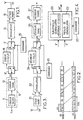
- les figures 1 et 3 sont respectivement des schémas synoptiques des parties émission et réception d'une station de radiocommunication selon l'invention ;
- la figure 2 est un diagramme temporel illustrant la structure de canaux de radiocommunication utilisés par une station selon l'invention ; et
- la figure 4 est un schéma partiel d'une variante avantageuse de la partie réception de la station.
- Figures 1 and 3 are respectively block diagrams of the transmission and reception parts of a radiocommunication station according to the invention;
- FIG. 2 is a time diagram illustrating the structure of radiocommunication channels used by a station according to the invention; and
- FIG. 4 is a partial diagram of an advantageous variant of the reception part of the station.
La partie émission de la station représentée sur
la figure 1 comporte une source 10 de signal de parole
codé SN. Dans l'exemple représenté, cette source traite un
signal de parole S qui lui est adressé, au moyen d'un
codeur source 11. Le signal de parole comprimé délivré par
le codeur 11 est fourni à un codeur canal 12 qui, de façon
connue, lui applique un codage correcteur d'erreurs et/ou
un entrelacement. Le signal de parole codé SN est
constitué par le signal du codeur canal 12. Il présente un
débit numérique donné D fixé par les caractéristiques des
codeurs 11 et 12.The broadcast part of the station represented on
FIG. 1 comprises a
La source 10 de signal de parole codé représentée
sur la figure 1 peut être celle incluse dans un terminal
portatif, le signal S étant alors issu du microphone du
terminal. Elle peut également être incluse dans une
station de base si le signal de parole S est disponible au
niveau de cette station de base. Si en revanche la station
de base dispose du signal codé SN mais non du signal
d'origine S, la source du signal de parole codé est
constituée par les parties réception et traitement de la
station qui restituent le signal numérique SN à
transmettre.The
La partie émission de la station comporte un
modulateur 15 qui reçoit un signal numérique obtenu à
partir du signal de parole codé SN. De façon classique, le
modulateur 15 délivre deux composantes en quadrature I, Q
en bande de base, qu'un étage radio associé 16 mélange à
deux ondes en quadrature à une fréquence porteuse, pour
produire le signal radio SR émis par l'antenne de la
station.The broadcast part of the station includes a
Comme symbolisé par deux commutateurs 17 sur la
représentation schématique de la figure 1, la station de
radiocommunication possède deux modes de fonctionnement.As symbolized by two
Dans le premier mode, le signal de parole codé SN
est directement adressé à l'entrée du modulateur 15. Dans
le second mode, ce signal SN est fourni à l'entrée d'un
codeur à redondance 18 dont la sortie fournit le signal
appliqué au modulateur 15. Ce codeur à redondance 18
présente un rendement de codage de la forme K/N avec
0<K<N, c'est-à-dire que pour K symboles du signal de
parole codé SN reçus, il délivre N symboles à l'entrée du
modulateur 15.In the first mode, the coded speech signal SN
is directly addressed to the input of
Dans un mode de réalisation simple de l'invention,
le codeur à redondance 18 peut être un codeur convolutif.
Dans l'exemple représenté, c'est un codeur convolutif
CC(2,1,3) de rendement ½ (K=1, N=2).In a simple embodiment of the invention,
the
Le modulateur 15 applique le même schéma de
modulation dans les deux modes de fonctionnement de la
station. The
On considère à titre d'exemple le cas d'un système
FDMA dans lequel le modulateur 15 admet un débit numérique
d'entrée de 16 kbit/s, avec des canaux radioélectriques de
largeur de 12,5 kHz. Le débit numérique moyen D du signal
SN issu de la source 10 est plus faible que cette valeur
de 16 kbit/s, dans un rapport K/N. Il est de D=8 kbit/s
dans l'exemple considéré. La source 10 délivre le signal
SN sous forme de trames binaires successives, de durée Δt
comprise entre 10 et 30 ms, par exemple Δt=20 ms. Pour
laisser de la place aux bits de redondance lorsque le
codeur 18 est utilisé, seulement une période de trame de
durée Δt sur deux est occupée par une trame du signal SN
constituée de symboles binaires à une cadence instantanée
de 16 kbit/s.We consider as an example the case of a system
FDMA in which the
Ainsi, dans le premier mode de fonctionnement de
la station, le signal radio SR résultant de la
transformation par le modulateur 15 du signal SN issu de
la source 10 occupe seulement une fraction K/N du temps
sur la fréquence porteuse. Ceci est illustré sur la
première ligne de la figure 2 montrant une communication 1
dont les trames successives 1a,1b,1c... occupent un
intervalle de temps Δt sur deux. Les autres intervalles de
temps peuvent être utilisés pour créer un autre canal
logique utilisable pour une autre communication radio
(trame 2a,2b,2c... d'une autre communication 2).So in the first mode of operation of
the station, the SR radio signal resulting from the
transformation by the
Dans le second mode, le codeur à redondance 18
fournit au modulateur 15 un signal à 16 kbit/s à plein
temps. Chaque trame 1a,1b,1c... occupe une durée
(N/K).Δt=2. Δt, de sorte que le signal radio SR résultant
de la sortie de la source 10 occupe la totalité du temps
sur la fréquence porteuse, c'est-à-dire N/K fois la
fraction correspondante dans le premier mode. Comme le
montre la seconde ligne de la figure 2, le canal physique
n'est pas capable d'accueillir une autre communication
dans le second mode. In the second mode, the
Le premier mode de fonctionnement augmente donc les capacités de trafic par rapport au second mode. Ce premier mode convient pour des zones à forte densité de trafic telles que des zones urbaines.The first operating mode therefore increases traffic capacities compared to the second mode. This first mode is suitable for areas with high density of traffic such as urban areas.
En revanche, le second mode, grâce à la redondance
introduite par le codeur 18, améliore la sensibilité des
récepteurs de 3 à 5 dB dans le cas où K/N=1/2. En d'autres
termes, la portée de la communication peut être augmentée,
de sorte que le second mode convient bien pour des zones
où la densité géographique d'installation de stations de
base est relativement faible.On the other hand, the second mode, thanks to the redundancy
introduced by the
On observe que cette bonne adaptation de la
station à différents environnements est obtenue en
utilisant la même source de signal de parole codé 10 et la
même chaíne de modulation 15,16. Il suffit essentiellement
de prévoir le codeur à redondance 18 dont la structure est
très simple, ainsi que des moyens de commande appropriés
pour le mettre en service sélectivement selon
l'environnement.We observe that this good adaptation of the
station in different environments is obtained by
using the same source of coded
Ces moyens de commande sont constitués par un
module 20 sur le schéma de la figure 1. Le fonctionnement
de ce module 20 est le suivant. Lors de l'échange de
signalisation entre une station de base et un terminal
portatif, précédant l'établissement d'une communication
sur un canal de trafic, la station de base notifie au
terminal portatif quel mode de fonctionnement doit être
utilisé. Ce mode dépendra essentiellement du site où se
trouve la station de base. Néanmoins, on peut observer que
la même station de base supportant plusieurs
communications avec des terminaux portatifs à un instant
donné, peut parfaitement fonctionner selon des modes
différents pour ces communications. Ainsi, la fixation du
mode de fonctionnement pourrait dépendre de paramètres
tels qu'une priorité affectée à une communication par
rapport à d'autres (par exemple, on pourrait prévoir
qu'une communication prioritaire s'effectue dans le second
mode, de meilleure sensibilité, même dans des zones à
forte densité de trafic). On peut également concevoir des
protocoles dans lesquels le mode de fonctionnement utilisé
pour une communication donnée dépendrait de la qualité du
lien radio observée en cours de communication.These control means are constituted by a
Une fois que les deux stations connaissent le mode
de fonctionnement à adopter, leurs modules 20 commandent
la mise en service ou la désactivation de leurs codeurs à
redondance 18 et de leurs décodeurs associés, pour la
transmission des signaux de phonie sur le canal de trafic.Once both stations know the mode
of operation to be adopted, their
Si le système de radiocommunication supporte des communications en mode talkie-walkie, c'est-à-dire directement de terminal portatif à terminal portatif, il est préférable d'effectuer ces communications dans le second mode, pour simplifier les problèmes de synchronisation.If the radiocommunication system supports communications in walkie-talkie mode, i.e. directly from portable terminal to portable terminal, it is best to make these communications in the second mode, to simplify the problems of synchronization.
Les canaux de communs de signalisation, utilisés
notamment par la station de base pour notifier aux
terminaux portatifs le mode de fonctionnement à utiliser,
sont fondés sur le second mode de fonctionnement, c'est-à-dire
que les signaux de signalisation sont fournis à
l'entrée du codeur à redondance 18 avant d'être appliqués
au modulateur 15. Ainsi, les terminaux portatifs qui se
trouvent proches de la limite de sensibilité du second
mode peuvent décoder correctement les informations de
signalisation transmises. Une protection complémentaire de
ces informations de signalisation est prévue compte tenu
de leur importance. Ainsi, les informations de
signalisation sont appliquées à un autre codeur correcteur
d'erreurs avant d'être transmises au codeur à redondance
18, afin que la station réceptrice puisse détecter et/ou
corriger des erreurs de transmission des informations de
signalisation. Cet autre codeur à redondance applique de
préférence un code en blocs, tel par exemple un code BCH
ou Reed-Solomon. Common signaling channels used
in particular by the base station to notify
portable terminals the operating mode to be used,
are based on the second mode of operation, i.e.
that signaling signals are supplied to
input from
La partie réception de la station, dont la
figure 1 montre la partie émission, est représentée
schématiquement sur la figure 3. Cette partie réception
est prévue pour traiter le signal radio SR' reçu depuis un
émetteur selon la figure 1. De façon classique, un étage
radio 21 convertit ce signal SR' en deux composantes en
quadrature en bande de base I',Q' qui sont adressées au
démodulateur 22. Un module de commande 20 met en service
sélectivement un décodeur 24 selon le mode de
fonctionnement utilisé. L'estimation SN' du signal de
parole codé SN est restituée en sortie du démodulateur 22
dans le premier mode de fonctionnement, et en sortie du
décodeur 24 dans le second mode de fonctionnement.The reception part of the station, including the
figure 1 shows the transmission part, is represented
schematically in Figure 3. This reception part
is intended to process the radio signal SR 'received from a
transmitter according to FIG. 1. Conventionally, a
Le démodulateur 22 effectue les opérations duales
de celles du modulateur 15. Le décodeur 24 exploite la
redondance introduite par le codeur 18 pour détecter et/ou
corriger d'éventuelles erreurs de transmission. Il est par
exemple constitué par un treillis de décodage opérant
selon l'algorithme de Viterbi. L'estimation SN' du signal
de parole codé est fournie à une chaíne de traitement 25,
comportant par exemple un décodeur canal 26 et un décodeur
source 27 correspondant respectivement aux codeurs 12 et
11 de l'émetteur.
Dans le mode de réalisation de la figure 3, le
codeur 24 apporte un gain de réception de l'ordre de 3 dB
dans le second mode de fonctionnement par rapport au
premier mode, dans le cas où K/N=1/2.In the embodiment of Figure 3, the
Ce gain peut être encore amélioré en utilisant
deux démodulateurs 22,30, sélectionnés par le module de
commande 20 selon le mode de fonctionnement, comme
représenté sur la figure 4. Le démodulateur 22, utilisé
dans le premier mode de fonctionnement est semblable à
celui utilisé dans la forme de réalisation selon la figure
3. C'est par exemple un treillis de démodulation mettant
en oeuvre l'algorithme de Viterbi sur la base des états du
modulateur numérique 15 de la figure 1. L'autre
démodulateur 30 délivre directement l'estimation SN' du
signal de parole codé à partir des composantes I',Q' dans
le second mode de fonctionnement. Ce démodulateur 30
combine les états du codeur à redondance 18 et du
modulateur numérique 15 de l'émetteur conformément au
principe des modulations codées (voir G. Ungerboeck
« Channel Coding with Multilevel/Phase Signals », IEEE
Transactions on Information Theory, Vol. IT-28, n° 1,
janvier 1982). Ce démodulateur 30 peut notamment être un
supertreillis de démodulation et de décodage, fonctionnant
selon l'algorithme de Viterbi avec des états combinés de
modulation et de codage CC(2,1,3). Le démodulateur 30
permet d'obtenir des gains de réception allant jusqu'à 5
dB environ dans le second mode par rapport au premier
mode, dans le cas où K/N=1/2.This gain can be further improved by using
two demodulators 22.30, selected by the
Claims (9)
- A digital radio communication station, comprising a coded speech signal source (10) having a given digital rate (D), and modulating means (15, 16) for producing a radio signal (SR) from the coded speech signal (SN) provided by the source, characterised in that it further includes a redundancy encoder (18) with a coding rate of the form K/N, where K and N are integers such that 0<K<N, and control means (20) for selecting an operating mode of the station from at least a first operating mode where the modulating means directly receive the coded speech signal provided by the source and convert it into a radio signal occupying a determined fraction of time on a carrier frequency, and a second operating mode where the redundancy encoder receives the coded speech signal provided by the source and the modulating means receive the output signal from the redundancy encoder and convert it into a radio signal occupying N/K times said determined fraction of time on a carrier frequency.
- A radio communication station in accordance with claim 1, further comprising an error-correcting encoder to which signaling data is applied, and wherein said signaling data is transmitted in the second operating mode, the output from said error-correcting encoder being fed to the input of the K/N-rate redundancy encoder (18).
- A radio communication station in accordance with claim 2, wherein said error-correcting encoder applies a block code.
- A radio communication station in accordance with any one of the preceding claims, wherein K=1 and N=2.
- A radio communication station in accordance with any one of the preceding claims, wherein the K/N-rate redundancy encoder is a convolutional encoder (18).
- A radio communication station in accordance with any one of the preceding claims, wherein said determined fraction is equal to K/N, and the occupancy of a carrier frequency is distributed in uniform time intervals (Δt), fully allocated to the coded speech signal source (10) in the second operating mode, and uniformly allocated in the proportion K/N in the first operating mode.
- A radio communication station in accordance with claim 6, wherein said time intervals (Δt) correspond to a frame of the coded speech signal.
- A radio communication station in accordance with claim 6 or 7, wherein said time intervals (Δt) are of 10 to 30 ms.
- A radio communication station in accordance with any one of the preceding claims, further comprising reception means (21-25) for processing a radio signal (SR') transmitted from another station which also has the two operating modes, the reception means comprising a first demodulator (22) which, in the first operating mode, carries out operations dual to those of the modulator (15) of the other station, and a second demodulator (30) used in the second operating mode and combining the states of the redundancy encoder (18) and of the modulating means (15) of the other station.
Applications Claiming Priority (2)
| Application Number | Priority Date | Filing Date | Title |
|---|---|---|---|
| FR9710214A FR2767245B1 (en) | 1997-08-08 | 1997-08-08 | DIGITAL RADIO COMMUNICATION STATION |
| FR9710214 | 1997-08-08 |
Publications (2)
| Publication Number | Publication Date |
|---|---|
| EP0896443A1 EP0896443A1 (en) | 1999-02-10 |
| EP0896443B1 true EP0896443B1 (en) | 2004-07-21 |
Family
ID=9510189
Family Applications (1)
| Application Number | Title | Priority Date | Filing Date |
|---|---|---|---|
| EP98402009A Expired - Lifetime EP0896443B1 (en) | 1997-08-08 | 1998-08-06 | Digital radio communication station |
Country Status (7)
| Country | Link |
|---|---|
| US (1) | US6442209B1 (en) |
| EP (1) | EP0896443B1 (en) |
| AT (1) | ATE271730T1 (en) |
| CA (1) | CA2244562A1 (en) |
| DE (1) | DE69825105T2 (en) |
| FR (1) | FR2767245B1 (en) |
| SG (1) | SG65089A1 (en) |
Cited By (1)
| Publication number | Priority date | Publication date | Assignee | Title |
|---|---|---|---|---|
| US7730296B2 (en) | 2003-02-12 | 2010-06-01 | Broadcom Corporation | Method and system for providing synchronous running encoding and encryption |
Families Citing this family (6)
| Publication number | Priority date | Publication date | Assignee | Title |
|---|---|---|---|---|
| US6563863B1 (en) | 1998-06-22 | 2003-05-13 | Ati International Srl | Computer modem |
| FR2793978B1 (en) * | 1999-05-19 | 2001-08-03 | Matra Nortel Communications | METHOD FOR BROADCASTING RADIO SIGNALS FROM A RADIO COMMUNICATION BASE STATION, BASE STATIONS AND MOBILE TERMINALS FOR CARRYING OUT SUCH A METHOD |
| FR2793988B1 (en) | 1999-05-19 | 2003-01-31 | Matra Nortel Communications | METHOD FOR RADIOCOMMUNICATION BETWEEN A BASE STATION AND MOBILE TERMINALS, BASE STATIONS AND MOBILE TERMINALS FOR THE IMPLEMENTATION OF SUCH A METHOD |
| US6577639B1 (en) | 1999-06-01 | 2003-06-10 | Ati International Srl | Reducing modem transmit latency |
| US20060209780A1 (en) * | 2005-01-21 | 2006-09-21 | Nokia Corporation | Data transfer in TDMA system |
| EP2536053B1 (en) * | 2011-06-14 | 2014-08-13 | Telefonaktiebolaget L M Ericsson (publ) | Device and method for conditionally controlling interference |
Family Cites Families (14)
| Publication number | Priority date | Publication date | Assignee | Title |
|---|---|---|---|---|
| AU5589086A (en) * | 1986-03-25 | 1987-10-20 | Motorola, Inc. | Method and apparatus for controlling a tdm communication device |
| KR950007498B1 (en) * | 1990-11-30 | 1995-07-11 | 가부시끼가이샤 도시바 | Dual mode cellular radio communication apparatus having an echo canceller employed in both analog and digital modes |
| ATE233971T1 (en) | 1991-05-13 | 2003-03-15 | Xircom Wireless Inc | TWO-MODE TRANSMITTER/RECEIVER |
| US6101177A (en) * | 1992-03-30 | 2000-08-08 | Telefonaktiebolaget Lm Ericsson | Cell extension in a cellular telephone system |
| CA2115445A1 (en) * | 1992-06-22 | 1994-01-06 | Masami Abe | Device for and method of continuing bit errors and device for and method of identifying signals |
| JP3212169B2 (en) * | 1993-01-06 | 2001-09-25 | 株式会社東芝 | Wireless communication system and base station |
| US5491719A (en) * | 1993-07-02 | 1996-02-13 | Telefonaktiebolaget Lm Ericsson | System for handling data errors on a cellular communications system PCM link |
| JP2812192B2 (en) * | 1994-03-08 | 1998-10-22 | 日本電気株式会社 | Radio channel selection method and radio channel selection system |
| US5490168A (en) * | 1994-07-08 | 1996-02-06 | Motorola, Inc. | Method and system for automatic optimization of data throughput using variable packet length and code parameters |
| EP0734185A2 (en) * | 1995-03-23 | 1996-09-25 | Hughes Electronics | DTMF tone transmission in a voice communication system |
| US5883899A (en) * | 1995-05-01 | 1999-03-16 | Telefonaktiebolaget Lm Ericsson | Code-rate increased compressed mode DS-CDMA systems and methods |
| GB9514956D0 (en) | 1995-07-21 | 1995-09-20 | British Telecomm | Transmission of digital signals |
| KR100551001B1 (en) | 1995-09-22 | 2006-07-06 | 퍼시픽 커뮤니케이션 싸이언스 인코포레이티드 | A cellular communication system with multiple code rates |
| US5953376A (en) * | 1996-09-26 | 1999-09-14 | Lucent Technologies Inc. | Probabilistic trellis coded modulation with PCM-derived constellations |
-
1997
- 1997-08-08 FR FR9710214A patent/FR2767245B1/en not_active Expired - Lifetime
-
1998
- 1998-08-04 CA CA002244562A patent/CA2244562A1/en not_active Abandoned
- 1998-08-06 SG SG1998002912A patent/SG65089A1/en unknown
- 1998-08-06 EP EP98402009A patent/EP0896443B1/en not_active Expired - Lifetime
- 1998-08-06 AT AT98402009T patent/ATE271730T1/en not_active IP Right Cessation
- 1998-08-06 US US09/129,791 patent/US6442209B1/en not_active Expired - Lifetime
- 1998-08-06 DE DE69825105T patent/DE69825105T2/en not_active Expired - Lifetime
Cited By (2)
| Publication number | Priority date | Publication date | Assignee | Title |
|---|---|---|---|---|
| US7730296B2 (en) | 2003-02-12 | 2010-06-01 | Broadcom Corporation | Method and system for providing synchronous running encoding and encryption |
| US8024558B2 (en) | 2003-02-12 | 2011-09-20 | Broadcom Corporation | Method and system for providing synchronous running encoding and encryption |
Also Published As
| Publication number | Publication date |
|---|---|
| SG65089A1 (en) | 1999-05-25 |
| FR2767245B1 (en) | 1999-10-15 |
| US6442209B1 (en) | 2002-08-27 |
| CA2244562A1 (en) | 1999-02-08 |
| DE69825105D1 (en) | 2004-08-26 |
| ATE271730T1 (en) | 2004-08-15 |
| DE69825105T2 (en) | 2005-09-01 |
| FR2767245A1 (en) | 1999-02-12 |
| EP0896443A1 (en) | 1999-02-10 |
Similar Documents
| Publication | Publication Date | Title |
|---|---|---|
| US5197061A (en) | Device for the transmission of digital data with at least two levels of protection and corresponding reception device | |
| EP1523116A2 (en) | System and method for transmitting auxiliary information on a subcarrier of a broadcast transmission | |
| EP1087584B1 (en) | Self-synchronizing convolutional interleaving for multicarrier transmission, particularly for DAB | |
| EP0095959B1 (en) | Frequency hopping radiocommunication system | |
| EP1547289B1 (en) | Reception of a signal modulated according to a multilevel coding technique | |
| JP4030675B2 (en) | Apparatus for providing a plurality of digitally modulated signals and method for receiving a plurality of signals | |
| US6320850B1 (en) | Satellite communication adaptive control coding | |
| US5642384A (en) | Trellis coded modulation scheme with low envelope variation for mobile radio by constraining a maximum modulus of a differential phase angle | |
| US5235621A (en) | Receiver systems | |
| EP0578313A1 (en) | Concatenated coding for OFDM transmission | |
| JPH07202855A (en) | Data transmitter | |
| CN1784875A (en) | Apparatus and method for use in iterative decoding | |
| EP1107492A1 (en) | Signalling method in a radio communication system, transmitters, receivers and repeaters for performing this method | |
| EP0896443B1 (en) | Digital radio communication station | |
| EP0947069B1 (en) | Receiver decoder circuitry, and associated method, for decoding a channel encoded signal | |
| FR2802369A1 (en) | Time multiplexed radio communications frequency carrier receiver having learning sequence symbols and demodulation estimates start/end sequence cycle with output logic/estimation combination. | |
| US6823488B1 (en) | Packet binary convolutional codes | |
| EP1129538B1 (en) | Device and method for receiving with at least two reception channels, and corresponding use | |
| EP0887950A1 (en) | Base station with antennas diversity for the transmission of unidirectional channels and corresponding method | |
| CA2280585A1 (en) | Packet binary convolutional codes | |
| US7336683B1 (en) | Efficient communication system for reliable frame transmission over broad SNR ranges | |
| US6661853B1 (en) | Method and apparatus for maximal-ratio combining of received frame data | |
| EP1047217A2 (en) | Method and system for receiving and decoding digital signals | |
| EP0821500B1 (en) | Multiple decoding | |
| KR100403086B1 (en) | Space-time trellis code construction method for wireless communications |
Legal Events
| Date | Code | Title | Description |
|---|---|---|---|
| PUAI | Public reference made under article 153(3) epc to a published international application that has entered the european phase |
Free format text: ORIGINAL CODE: 0009012 |
|
| AK | Designated contracting states |
Kind code of ref document: A1 Designated state(s): AT BE CH DE ES GB GR IE IT LI PT |
|
| AX | Request for extension of the european patent |
Free format text: AL;LT;LV;MK;RO;SI |
|
| 17P | Request for examination filed |
Effective date: 19990111 |
|
| AKX | Designation fees paid |
Free format text: AT BE CH DE ES GB GR IE IT LI PT |
|
| AXX | Extension fees paid |
Free format text: LT PAYMENT 19990111;LV PAYMENT 19990111;RO PAYMENT 19990111;SI PAYMENT 19990111 |
|
| RAP1 | Party data changed (applicant data changed or rights of an application transferred) |
Owner name: NORTEL NETWORKS FRANCE |
|
| GRAP | Despatch of communication of intention to grant a patent |
Free format text: ORIGINAL CODE: EPIDOSNIGR1 |
|
| GRAS | Grant fee paid |
Free format text: ORIGINAL CODE: EPIDOSNIGR3 |
|
| GRAA | (expected) grant |
Free format text: ORIGINAL CODE: 0009210 |
|
| AK | Designated contracting states |
Kind code of ref document: B1 Designated state(s): AT BE CH DE ES GB GR IE IT LI PT |
|
| AX | Request for extension of the european patent |
Extension state: LT LV RO SI |
|
| PG25 | Lapsed in a contracting state [announced via postgrant information from national office to epo] |
Ref country code: IT Free format text: LAPSE BECAUSE OF FAILURE TO SUBMIT A TRANSLATION OF THE DESCRIPTION OR TO PAY THE FEE WITHIN THE PRE;WARNING: LAPSES OF ITALIAN PATENTS WITH EFFECTIVE DATE BEFORE 2007 MAY HAVE OCCURRED AT ANY TIME BEFORE 2007. THE CORRECT EFFECTIVE DATE MAY BE DIFFERENT FROM THE ONE RECORDED.SCRIBED TIME-LIMIT Effective date: 20040721 Ref country code: IE Free format text: LAPSE BECAUSE OF FAILURE TO SUBMIT A TRANSLATION OF THE DESCRIPTION OR TO PAY THE FEE WITHIN THE PRESCRIBED TIME-LIMIT Effective date: 20040721 Ref country code: AT Free format text: LAPSE BECAUSE OF FAILURE TO SUBMIT A TRANSLATION OF THE DESCRIPTION OR TO PAY THE FEE WITHIN THE PRESCRIBED TIME-LIMIT Effective date: 20040721 |
|
| REG | Reference to a national code |
Ref country code: GB Ref legal event code: FG4D Free format text: NOT ENGLISH |
|
| REG | Reference to a national code |
Ref country code: CH Ref legal event code: EP |
|
| REG | Reference to a national code |
Ref country code: IE Ref legal event code: FG4D Free format text: FRENCH |
|
| REF | Corresponds to: |
Ref document number: 69825105 Country of ref document: DE Date of ref document: 20040826 Kind code of ref document: P |
|
| PG25 | Lapsed in a contracting state [announced via postgrant information from national office to epo] |
Ref country code: LI Free format text: LAPSE BECAUSE OF NON-PAYMENT OF DUE FEES Effective date: 20040831 Ref country code: CH Free format text: LAPSE BECAUSE OF NON-PAYMENT OF DUE FEES Effective date: 20040831 Ref country code: BE Free format text: LAPSE BECAUSE OF NON-PAYMENT OF DUE FEES Effective date: 20040831 |
|
| PG25 | Lapsed in a contracting state [announced via postgrant information from national office to epo] |
Ref country code: GR Free format text: LAPSE BECAUSE OF FAILURE TO SUBMIT A TRANSLATION OF THE DESCRIPTION OR TO PAY THE FEE WITHIN THE PRESCRIBED TIME-LIMIT Effective date: 20041021 |
|
| PG25 | Lapsed in a contracting state [announced via postgrant information from national office to epo] |
Ref country code: ES Free format text: LAPSE BECAUSE OF FAILURE TO SUBMIT A TRANSLATION OF THE DESCRIPTION OR TO PAY THE FEE WITHIN THE PRESCRIBED TIME-LIMIT Effective date: 20041101 |
|
| GBT | Gb: translation of ep patent filed (gb section 77(6)(a)/1977) |
Effective date: 20041021 |
|
| LTIE | Lt: invalidation of european patent or patent extension |
Effective date: 20040721 |
|
| BERE | Be: lapsed |
Owner name: NORTEL NETWORKS FRANCE Effective date: 20040831 |
|
| REG | Reference to a national code |
Ref country code: IE Ref legal event code: FD4D |
|
| REG | Reference to a national code |
Ref country code: CH Ref legal event code: PL |
|
| PLBE | No opposition filed within time limit |
Free format text: ORIGINAL CODE: 0009261 |
|
| STAA | Information on the status of an ep patent application or granted ep patent |
Free format text: STATUS: NO OPPOSITION FILED WITHIN TIME LIMIT |
|
| 26N | No opposition filed |
Effective date: 20050422 |
|
| BERE | Be: lapsed |
Owner name: *NORTEL NETWORKS FRANCE Effective date: 20040831 |
|
| PG25 | Lapsed in a contracting state [announced via postgrant information from national office to epo] |
Ref country code: PT Free format text: LAPSE BECAUSE OF NON-PAYMENT OF DUE FEES Effective date: 20041221 |
|
| REG | Reference to a national code |
Ref country code: DE Ref legal event code: R082 Ref document number: 69825105 Country of ref document: DE Representative=s name: , |
|
| REG | Reference to a national code |
Ref country code: GB Ref legal event code: 732E Free format text: REGISTERED BETWEEN 20130502 AND 20130508 |
|
| REG | Reference to a national code |
Ref country code: GB Ref legal event code: 732E Free format text: REGISTERED BETWEEN 20130509 AND 20130515 |
|
| REG | Reference to a national code |
Ref country code: DE Ref legal event code: R082 Ref document number: 69825105 Country of ref document: DE Representative=s name: BARDEHLE PAGENBERG PARTNERSCHAFT MBB PATENTANW, DE Effective date: 20140313 Ref country code: DE Ref legal event code: R082 Ref document number: 69825105 Country of ref document: DE Representative=s name: BARDEHLE PAGENBERG PARTNERSCHAFT MBB PATENTANW, DE Effective date: 20130508 Ref country code: DE Ref legal event code: R081 Ref document number: 69825105 Country of ref document: DE Owner name: APPLE INC., CUPERTINO, US Free format text: FORMER OWNER: NORTEL NETWORKS FRANCE, CHATEAUFORT, FR Effective date: 20140313 Ref country code: DE Ref legal event code: R081 Ref document number: 69825105 Country of ref document: DE Owner name: APPLE INC., US Free format text: FORMER OWNER: NORTEL NETWORKS FRANCE, CHATEAUFORT, FR Effective date: 20140313 |
|
| PGFP | Annual fee paid to national office [announced via postgrant information from national office to epo] |
Ref country code: GB Payment date: 20170802 Year of fee payment: 20 Ref country code: DE Payment date: 20170801 Year of fee payment: 20 |
|
| REG | Reference to a national code |
Ref country code: DE Ref legal event code: R071 Ref document number: 69825105 Country of ref document: DE |
|
| REG | Reference to a national code |
Ref country code: GB Ref legal event code: PE20 Expiry date: 20180805 |
|
| PG25 | Lapsed in a contracting state [announced via postgrant information from national office to epo] |
Ref country code: GB Free format text: LAPSE BECAUSE OF EXPIRATION OF PROTECTION Effective date: 20180805 |