EP0894639B1 - Colour copier - Google Patents
Colour copier Download PDFInfo
- Publication number
- EP0894639B1 EP0894639B1 EP98305327A EP98305327A EP0894639B1 EP 0894639 B1 EP0894639 B1 EP 0894639B1 EP 98305327 A EP98305327 A EP 98305327A EP 98305327 A EP98305327 A EP 98305327A EP 0894639 B1 EP0894639 B1 EP 0894639B1
- Authority
- EP
- European Patent Office
- Prior art keywords
- swath
- swaths
- printing
- ink droplet
- droplet density
- Prior art date
- Legal status (The legal status is an assumption and is not a legal conclusion. Google has not performed a legal analysis and makes no representation as to the accuracy of the status listed.)
- Expired - Lifetime
Links
- 238000010304 firing Methods 0.000 claims description 32
- 239000003086 colorant Substances 0.000 claims description 24
- 238000000034 method Methods 0.000 claims description 11
- 230000015572 biosynthetic process Effects 0.000 claims 5
- 238000005192 partition Methods 0.000 description 30
- 238000004364 calculation method Methods 0.000 description 5
- 230000000694 effects Effects 0.000 description 5
- 235000003642 hunger Nutrition 0.000 description 5
- 230000007246 mechanism Effects 0.000 description 5
- 230000037351 starvation Effects 0.000 description 5
- 230000008569 process Effects 0.000 description 4
- 241000872198 Serjania polyphylla Species 0.000 description 3
- 239000011159 matrix material Substances 0.000 description 3
- 238000003491 array Methods 0.000 description 2
- 238000010586 diagram Methods 0.000 description 2
- 230000002401 inhibitory effect Effects 0.000 description 2
- 239000007788 liquid Substances 0.000 description 2
- 230000009467 reduction Effects 0.000 description 2
- 239000002904 solvent Substances 0.000 description 2
- 230000002745 absorbent Effects 0.000 description 1
- 239000002250 absorbent Substances 0.000 description 1
- 230000009471 action Effects 0.000 description 1
- 230000003044 adaptive effect Effects 0.000 description 1
- 238000004458 analytical method Methods 0.000 description 1
- 230000015556 catabolic process Effects 0.000 description 1
- 238000006243 chemical reaction Methods 0.000 description 1
- 239000000470 constituent Substances 0.000 description 1
- 238000006731 degradation reaction Methods 0.000 description 1
- 230000003111 delayed effect Effects 0.000 description 1
- 230000001627 detrimental effect Effects 0.000 description 1
- 238000001035 drying Methods 0.000 description 1
- 239000002360 explosive Substances 0.000 description 1
- 230000006870 function Effects 0.000 description 1
- 230000000977 initiatory effect Effects 0.000 description 1
- 239000000463 material Substances 0.000 description 1
- 230000004048 modification Effects 0.000 description 1
- 238000012986 modification Methods 0.000 description 1
- 230000004044 response Effects 0.000 description 1
- 229920006395 saturated elastomer Polymers 0.000 description 1
- 238000010408 sweeping Methods 0.000 description 1
- XLYOFNOQVPJJNP-UHFFFAOYSA-N water Substances O XLYOFNOQVPJJNP-UHFFFAOYSA-N 0.000 description 1
Images

Classifications
-
- B—PERFORMING OPERATIONS; TRANSPORTING
- B41—PRINTING; LINING MACHINES; TYPEWRITERS; STAMPS
- B41J—TYPEWRITERS; SELECTIVE PRINTING MECHANISMS, i.e. MECHANISMS PRINTING OTHERWISE THAN FROM A FORME; CORRECTION OF TYPOGRAPHICAL ERRORS
- B41J2/00—Typewriters or selective printing mechanisms characterised by the printing or marking process for which they are designed
- B41J2/005—Typewriters or selective printing mechanisms characterised by the printing or marking process for which they are designed characterised by bringing liquid or particles selectively into contact with a printing material
- B41J2/01—Ink jet
- B41J2/21—Ink jet for multi-colour printing
-
- B—PERFORMING OPERATIONS; TRANSPORTING
- B41—PRINTING; LINING MACHINES; TYPEWRITERS; STAMPS
- B41J—TYPEWRITERS; SELECTIVE PRINTING MECHANISMS, i.e. MECHANISMS PRINTING OTHERWISE THAN FROM A FORME; CORRECTION OF TYPOGRAPHICAL ERRORS
- B41J19/00—Character- or line-spacing mechanisms
- B41J19/18—Character-spacing or back-spacing mechanisms; Carriage return or release devices therefor
- B41J19/20—Positive-feed character-spacing mechanisms
- B41J19/202—Drive control means for carriage movement
Definitions
- the present invention relates generally to a colour copier employing an inkjet printer, for example which can improve print quality images having densely inked areas by substantially reducing ink pen starvation, droplet trajectory errors, and fuzzy text edges.
- Inkjet printers are efficient, quiet and produce high quality print images in a relatively inexpensive manner when operated in low speed printing modes. Such quality is achieved by sweeping a large number of inkjet nozzles over a print medium and ejecting droplets of ink onto the medium in one or more matrix arrays of minute ink drop patterns. Such arrays are known as swaths and the individual ink droplets are defined as pixels. The quality of the print image is then determined by assuring that each ink droplet has a precise volume of ink that is applied to a specific location on the print medium without smearing.
- Buckling and curling are technical terms that describe the reaction of an absorbent material, such as bond paper, when a large volume of liquid is deposited in a concentrated area.
- Buckling which is a problem referred to as cockling, is the expansion of a paper surface upwardly as it absorbs the liquid solvent component of the ink, which is typically water.
- Curling on the other hand, is the twisting of the plane of the paper as a result of one side of the paper being saturated with ink while the other side of the paper remains dry.
- the outlet of the inkjet nozzle in order for an ink droplet to be accurately placed at a specific location on the print medium, the outlet of the inkjet nozzle must be disposed in close proximity to the paper surface. Placement of the nozzle relative to the paper surface however, must be sufficiently spaced to ensure that buckling will not result in the paper surface making contact with the nozzle surface.
- each nozzle in the inkjet print head has an inner chamber for receiving a precise volume of ink.
- the ink enters the chamber through an inlet under capillary action and is ejected from a nozzle outlet with an explosive force as the ink and its constituent solvent are heated rapidly by the application of electrical current to a firing resistor disposed within the chamber.
- the rapid evacuating of the colorant within the chamber has two effects.
- the ink exiting the chamber expands outwardly to form large and small puddles of ink on the receiving paper which result in fuzzy pixel edges if the nozzle is spaced too far from the paper surface.
- the ink entering the chamber rushes in against the back fire of the evacuating ink to create a turbulent inflow causing the incoming ink to rise and fall within the chamber as it dissipates its kinetic energy.
- This firing process is then repeated at a very rapid rate or frequency in order to deposit the large volumes of ink in concentrated areas on the paper. Should the frequency of firing be too rapid there is an immediate image degradation effect as either ink pen starvation or non precise volumes of ink result.
- puddles of ink may accumulate on the nozzle plate which in turn may cause undesired and unwanted droplet trajectory errors.
- the Kennedyer patent discloses a densitometer for adaptive control of ink drying time where a printer controller and an associated algorithm establishes a variable delay time between sweeps.
- the algorithm determines the maximum density of ink to be deposited in a given swath to control the amount of delay time between sweeps. In this manner rather than having a fixed delay time between individual sweeps, a variable delay time is implemented. This technique improves print quality at the expense of throughput and requires large amounts of processor time.
- the bayer et al. patent does not address the problems associated with ink pen starvation.
- EP-A-0,665,111 discloses an inkjet recording device that includes control means that operates in a first recording mode in which a recording covering the recording area is produced during one scanning operation and in a second recording mode in which a recording covering a portion of the recording area only is produced during one scanning operation.
- EP-A-0,382,023 discloses an inkjet recording device that includes control means that increases the number of recording heads to be used during recording of a recordable region formed by the total sum of all the discharge regions of a plural number of recording heads from initiation or recording onto a recording medium, reducing the number of recording heads to be used during recording of the recordable region in the recording completion region of the recording medium, and has one scanning width to be recorded by scanning by the recording head during recording as the feeding pitch of the recording medium.
- a preferred copier system includes a scanner having an associated memory unit for scanning and storing document images that are transferred via an interface unit to a high speed inkjet printer that switches printing speeds intra page from swath to swath depending upon ink density requirements for producing graphic and textual images in response to print commands from the scanner.
- Another embodiment includes a plurality of carriage mounted print head cartridges each having a plurality of inkjet nozzles for applying precise volumes of black and colorant ink droplets on a medium surface to form a full colour high density graphic image without smearing and without inhibiting carriage travel between sweeps.
- the copying system includes a printer controller that responds to print commands of a scanner by printing intra page swaths of image information at different printing rates and at different nozzle firing rates, where the printing and firing rates for forming each swath is determined based upon the densities of the black and colorant ink droplets to be ejected by the nozzles in each individual swath.
- Another embodiment provides a printing method for forming full color graphic images at a high throughput rate.
- the method comprises the steps of dividing a swath to be printed into a plurality of partitions, where each partition is a small matrix array of n columns by m rows of ink droplets and then determining for regions of overlapping partitions, the black droplet density and the color droplet density in each partition.
- the precise volume of black droplets and colorant droplets in each given swath of the image to be formed is applied to the print medium at one of two independent rates.
- a first high speed rate and high speed firing rate is applied when the density of the black ink droplets in each of the regions of a given swath does not exceed a predetermined threshold level regardless of the colorant ink droplet density in the swath.
- a second high speed rate is a high density graphics rate where the density of the black ink droplets in at least one of the regions in a given swath exceeds the predetermined threshold level, while the density of the colorant ink droplets in all the remaining regions of the given swath do not exceed the predetermined threshold level.
- the copier 8 utilizes a wet ink process for reproducing text and object images.
- the copier 8 includes a scanner 72 having a memory unit 74 for scanning and storing document images to be printed.
- the combination of the scanner 72 and its associated memory unit 74 facilitates rapid reproduction of the document images to be printed as the document images to be printed need only to be scanned a single time.
- the copier 8 In order to reproduce a hard copy of the document images stored in the memory unit 74, the copier 8 also includes a high speed, full color inkjet printer 10 that is coupled electrically to the scanner 72 via an interface unit 62.
- FIG. 3 is a fragmentary perspective view showing an exemplary embodiment of the copier 8 illustrating the printer 10 portion with its housing 28 and control panel 20.
- the printer 10 is shown with its cover 22 in an open position to help illustrate various major mechanical components of the printing system.
- the printer 10 generally includes a print controller 88 having an associated memory unit 64.
- the print controller 88 responds to the print commands send by the scanner 72 by receiving and storing the document images to be printed in a data area 66 of the memory unit 64.
- the memory unit 64 also includes a driver routine area 68 for storing routines that control the mechanical apparatuses forming part of the printer 10.
- the mechanical apparatuses that form part of the printer 10, that will be described hereinafter in greater detail, include a sheet feeding and stacking mechanism 90, a carriage mechanism 92 for driving movably a carriage unit 16 having a set of stalls for receiving one or more print cartridges 18.
- Each print cartridge includes a plurality of inkjet nozzles, such as an inkjet nozzle 92.
- FIG. 3 illustrates only one cartridge 18, with the remaining three stalls or bays being empty and marked with reference characters in parentheses thus: (18C), (18M), and (18Y) are the empty stalls for the cyan, magenta and yellow print cartridges.
- the high speed inkjet printer 10 responds to commands from the scanner 72 by printing full color or black print images on a sheet of paper 12 or other form of printing medium, such as a transparency which is retrieved mechanically from a medium supply tray 15 that holds a given amount of the printing medium.
- the given amount of printing medium that can be held by the supply tray 15 varies between a single sheet, such as the sheet 12, to a predetermined maximum quantity.
- the printer 10 operates in a single pass printing mode to cause one or more swaths of ink droplets, such as a swath 84 (FIG. 6), to be ejected on to the printing medium 12 to form a desired image.
- the swath 84 is formed in a pattern of individual dots at particular locations of an array defined for the printing medium 12. The locations are conveniently visualized as being small dots in a matrix array. The locations of the individual ink droplets are known as "dot positions," or "pixels.”
- the print carriage 16 having one or more print cartridges thereon, is supported from below on a slide rod 24 that permits the carriage 16 to move along a rectilinear path of travel whose direction is indicated generally at 86.
- the path of travel followed by the print carriage 16 is traverse to the path of travel followed by the sheet 12 as it passes through a print zone 14.
- the controller 88 responds causing the sheet feeding stacking mechanism 90 to retrieve and move the sheet 12 from the supply tray 15 along a medium path of travel within the printer 10 into the print zone 14.
- the sheet 12 is stopped temporarily for printing purposes.
- the carriage mechanism 92 causes the carriage 16 to scan across the sheet 12 allowing the print cartridges, such as the print cartridge 18 to eject drops of ink at appropriate times pursuant to the command of the print controller 88, wherein the timing of the application of the ink drops onto the sheet 12 corresponds to the pattern of pixels of the image being printed.
- a stepper motor in combination with a set of feed rollers (not shown) forming part of the sheet feeding stacking mechanism 90 cause the sheet 12 to be incrementally shifted or moved along its path of travel to a next printing position within the print zone 14.
- the carriage 16 is scanned across the sheet 12 in an opposite direction along its path of travel for printing a next swath of ink.
- the sheet 12 is moved from the print zone to an output tray 17. In this manner, the smearing of wet ink on the sheet 12 is prevented.
- the various ones of the ink jet nozzles on the print cartridges 18 eject ink to form a column of ink droplets whose height (x) is determined by the configuration and number of ink jet nozzles disposed on the print cartridge 18.
- the height of the column is expressed as a function of the number of rows of dots, which in the preferred embodiment is about N rows, where N is between about 104 and about 150.
- the width (y) of the column is determined by the length of the path of travel followed by the carriage as it travels across the paper medium 12.
- the resulting columns of ink droplets printed in one sweep of the carriage 16 across the medium 12 is commonly referred to a swath.
- the scanner 72 scans a document to be copied and stores its textual and object images in the memory unit 74. Once the document images to be printed have been stored in the memory unit 74, the scanner 72 causes a print command to be sent to the printer 10. The object or textual information to be printed is also sent to the printer 10 and is stored in the data area 66 of the memory unit 64 as a plot profile file.
- the controller 88 causes the received data to the stored in the form of plot profile files.
- the controller 88 while storing the received data utilizes a control algorithm 100 to determine the speed at which the object or textual information is to be printed. More particularly, the printer 10 has an optimum maximum printing speed wherein the carriage 16 travels along its rectilinear path of travel at a rate of about 1000 millimeters per second while firing the various inkjet nozzles at about a 12 Kilohertz rate.
- the carriage velocity and the firing rate of the inkjet nozzles determine the maximum throughput of the printer 10 when ink drop density on the medium is at a nominal level.
- the printer 10 when the ink drop density increases to a maximum level, the printer 10, under the control of the controller 88 and the algorithm 100, reduces its carriage velocity and nozzle firing rate intra page to allow sufficient time for the ink deposited onto the printing media 12 to dry. Stated otherwise, as will be explained hereinafter in greater detail, whenever the controller determines that ink drop densities have exceeded certain predetermined threshold levels in any given swath of information to be printed, the controller 88 causes that particular swath to be printed at a slower rate by reducing the velocity of the carriage unit 16 and by reducing the time between the firing of the nozzles.
- a first high density print mode has a carriage velocity of between about 1.0 meters per second and about 0.5 meters per second.
- a second high density print mode has a carriage velocity of between about 0.5 meters per second and about 0.25 meters per second.
- the printer 10 switches intra page on a swath by swath basis between these different high density printing modes depending upon the black ink droplet densities and the colorant ink droplet densities required by the individual ones of the swaths as will be explained hereinafter in greater detail.
- the controller 88 In order to switch printing speeds from swath to swath on an intra page basis, the controller 88 operating under the commands of the algorithm 100, divides the image to be printed into one or more swaths and further divides each swath into a given number of partitions, such as an N number of partitions 702-709 as generally indicated in FIG. 7A. Each partition is n columns wide by m rows high.
- the partitions are arranged in regions, such as regions 720-724 where each region is composed of two overlapping partitions 2n columns wide and m rows high.
- regions 720-724 where each region is composed of two overlapping partitions 2n columns wide and m rows high.
- the first and second regions 720 and 721 in swath 84 have a common overlapping area occupied by partition 703 whose relative location is indicated generally at A.
- n ranges between 16 columns and 512 columns. A more preferred range of n is between 32 columns and 256 columns and the most preferred value for n is 128 columns.
- m ranges between 2 rows and 128 rows. A more preferred range of m is between 4 rows and 64 rows, and the most preferred value for n is 32 rows.
- a density subroutine 200 determines the black dot density and the combined color dot density in each partition of each swath.
- the control or density algorithm 200 then analyzes the black and combined color dot densities within the rows to be printed and in overlapping regions having a width of 2n columns to establish the printing speed for each individual swath in the image to be printed so that the print sweep velocity is reduced when the black dot density in one or more regions of a given swath exceeds a fixed threshold density level and the color dot density level within all the other regions in the given swath are below the fixed threshold level.
- Table No. 1 is a look up table the controller 88 utilizes in determining whether to advance the carriage 16 at its high speed textual rate or at its lower high speed object or image rate.
- Threshold Value Preferred Value Range More Preferred Value Range Most Preferred Value Range Black Only 20%-100% 40%-90% 60% Black/Color 20%-100% 40%-90% 70% Color 0%-300% 30%-200% 70% Color Hue 0%-100% 20%-100% 50%
- the controller 88 causes the carriage 16 to sweep at its high speed textual rate of about 0.25 seconds per sweep with a pen firing rate of about 12 Kilo hertz and at about 0.50 seconds per sweep with a pen firing rate of about 6 Kilo hertz when the black dot density is equal to or greater than 60%.
- the algorithm 100 examines color density as a factor because a sweep velocity reduction may cause a color hue shift, which in turn, will effect print quality. Therefore, color hue shift is minimized in regions where color and black are mixed. In short, print speed reduction is avoided when a sweep contains sufficiently dense color in regions with low black dot density.
- the controller 88 begins the algorithm 100 at a start command step 502 when power is applied to the controller 88.
- the controller 88 then enters an idle mode at a decision step 504 waiting for the scanner 72 to send a print command.
- the printer control program 100 advances to a command step 506 and reads the first page of information to be printed dividing the information into a series of profile or swath files.
- the control program causes the controller 88 to divide the first swath, such as the swath 84, into N number of partitions, where each partition is n columns wide and m rows in height.
- the control program causes the controller 88 to allocate the partitions, such as the partitions 702-709 into a plurality of overlapping regions, where each region comprises twice the number of columns in any given partition.
- the control program 100 then steps to a decision command 512 to determine whether the partitioned swath was the last swath relative to the total number of swaths on the page of information to be printed.
- control program 100 advances to a command step 514 that causes the next swath to be divided into N number of partitions in the same manner as described previously.
- controller 88 steps to the allocation step 510 and proceeds as described previously.
- the control program 100 advances to a call command that calls a DENSITY CALCULATION subroutine 200 that will be described hereinafter in greater detail.
- the control program advances to a decision command 518 to determine whether the page of information printed was the last page of information associated with the print command sent by the scanner 72. In this regard, if there are no more pages of information to be printed, the control program proceeds to the idle mode at the decision command 504 to wait for another print command from the scanner 72.
- step 518 if it is determined that additional pages of information need to be printed, the control program goes to a read command step 522 and causes the next page of information to be retrieved from the memory unit 64 and divides it into one or more profile swath files. The control program 100 then returns to the command step 508 and proceeds as described previously.
- the control program 100 proceeds to subroutine 200 at a start step 201 and immediately advances to a command step 202 to determine the black dot density for each partition in a current swath, such as the swath 84.
- the control program advances to another command step 204 to determine the color dot density for each partition in the current swath.
- the subroutine 200 advances to a call step 206 that causes a SWEEP RATE subroutine 250 to be executed.
- the SWEEP RATE subroutine 250 will be described hereinafter in greater detail.
- the SWEEP RATE subroutine 250 helps facilitating establishing the velocity rate of the carriage 16 and the time delay between the firing of the print cartridges 18 and their associated nozzles.
- subroutine control returns to a decision step 208 to determine whether the last region has been analyzed. If the last region has not been analyzed the program goes to the call step 206 and proceeds as described previously. If the last region was analyzed the program goes to a decision step210 that determines whether the maximum color is greater than the color hue threshold level for the given sweep. If the maximum color is greater than the color hue threshold level, the program proceeds to a command step 214 that set the carriage velocity to a maximum printing rate of x+w millimeters per second and sets the pen firing rate to a maximum pen firing rate of Z times per second.
- step 210 determines whether the maximum color is not greater than the color hue threshold level. If at step 210 it is determined that the maximum color is not greater than the color hue threshold level, the program proceeds to a decision step 212 that determines whether the slow sweep flag has been set when the program executed the SWEEP RATE subroutine 250 as will be described hereinafter in greater detail.
- step 212 If at step 212 it is determined that the slow sweep flag has not been set, the program goes to the command step 214 and proceeds as described previously. If at step 212 it is determined that the slow sweep flag was set, the program advances to a command step 216 that causes the carriage velocity to be set to the slow rate of x millimeters per second and the pen firing rate set to a slow firing rate of R times per second.
- the program advances to a decision step 218 to determine whether all of the sweeps on the first page of information to be printed have been analyzed. If all of the swaths have not been analyzed, the program goes to the command step 202 and proceeds as described previously. If the last swath has been analyzed, the program goes to an end step 220 that causes the program to return to step 518 as best seen in FIG. 5.
- the maximum velocity of x+w millimeters per second is only limited by the maximum velocity that the carriage can travel. This maximum velocity is about 1250 millimeters per second. A more preferred maximum velocity is about 1125 millimeters per second, and the most preferred maximum velocity is about 1000 millimeters per second.
- the delay time between pen firings is set to about 12 Khz rate at step 214.
- the delay times of Z and R are substantially different from one another.
- the delay time Z is at about a 6.0 Kilohertz rate while the delay time R is at about a 12 Kilohertz rate.
- the delay times of Z and R should not be confused with the firing cycle time of the print head cartridge which is fixed at about 2 microseconds regardless of the delay times between pen firings.
- the SWEEP RATE subroutine 250 is accessed from the call command step 206 and begins at a start command 300.
- the subroutine then continues to a decision step 302 that determines whether the color density level in the current region is greater than the color density threshold level. If the color density is greater than the color threshold level, the subroutine advances to another decision step 304 to determine whether the black dot density of the current region is greater than the black with color threshold level.
- the subroutine 250 proceeds to a decision step 320.
- step 304 if at step 304 a determination is made that the black dot density is not greater than the black with color threshold level, the subroutine advances to the determination step 320 that will be described hereinafter.
- step 304 If at step 304 a determination is made that the black density is greater than the black with color threshold level, the subroutine proceeds to the command step 306 and sets a SLOW SWEEP condition flag that will be utilized subsequently to determine whether a fast or slow sweep rate will be applied to the current swath under analysis as will be described in greater detail.
- the subroutine 250 advances to the decision step 320 as mentioned previously.
- step 320 If the condition in step 320 is not true, the subroutine advance directly to the decision step 324, where a determination is made whether the black dot density in the current region is greater than the black only threshold level. If the black dot density in the current region is not greater than the black only threshold level, the subroutine advances to the command step 306 and sets the SLOW SWEEP condition. After the SLOW SWEEP condition is set at step 306, the subroutine goes to a RETURN step 338 that returns the program to step 208 to examine another region in the swath.
- the subroutine proceed to a determination step 326 that determines whether the color dot density in the current region is greater than the maximum color level.
- step 326 if a determination is made that the color dot density is not greater than the maximum color level, the subroutine goes to the return step 338 that returns the program to step 208 as described previously. Otherwise, the next step is a command step 328 where the controller 88 sets a flag to indicate that maximum color is maximum density. After executing the command step 328 the program advances to the return step 338 and proceeds as described previously.
- the printer 10 operates in two high speed intra page printing modes that switch from one to another under the control of the controller 88 depending upon the ink drop density from swath to swath.
- the high speed high density rate is about one half the high speed low density rate relative to both the carriage velocity and the firing frequency rate of the individual nozzles.
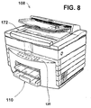
- the copier 108 is substantially similar to the copier 8 and includes a printer 110 and a scanner 172 having a control panel 120. As best seen in FIG. 8, the only difference between the copier 8 and the copier 108 is the physical configuration of the control panel 120 and the physical arrangement of the printer 110 and the scanner 172.
- each partition in a given swath is greater in dimension than the number of rows in each partition. It is contemplated that the width of each partition in a given swath may be substantially less or equal in dimension to the number of rows in each partition.
Landscapes
- Ink Jet (AREA)
Description
- The present invention relates generally to a colour copier employing an inkjet printer, for example which can improve print quality images having densely inked areas by substantially reducing ink pen starvation, droplet trajectory errors, and fuzzy text edges.
- Inkjet printers are efficient, quiet and produce high quality print images in a relatively inexpensive manner when operated in low speed printing modes. Such quality is achieved by sweeping a large number of inkjet nozzles over a print medium and ejecting droplets of ink onto the medium in one or more matrix arrays of minute ink drop patterns. Such arrays are known as swaths and the individual ink droplets are defined as pixels. The quality of the print image is then determined by assuring that each ink droplet has a precise volume of ink that is applied to a specific location on the print medium without smearing.
- While such low speed inkjet printers have been satisfactory for many applications, there has been a constant demand for higher speed printers that produce high quality full color images. Meeting the demand for higher throughput while producing high quality, high density images, however, has not been achieved easily. In this regard, in order to produce full vibrant colors on a print medium, large volumes of ink must be deposited in concentrated areas on the medium. Such deposits produce vibrant colors but also cause the print medium to buckle and curl, which in turn, greatly effects throughput and print quality as will be explained.
- Buckling and curling are technical terms that describe the reaction of an absorbent material, such as bond paper, when a large volume of liquid is deposited in a concentrated area. Buckling which is a problem referred to as cockling, is the expansion of a paper surface upwardly as it absorbs the liquid solvent component of the ink, which is typically water. Curling, on the other hand, is the twisting of the plane of the paper as a result of one side of the paper being saturated with ink while the other side of the paper remains dry.
- The effects of cockling and curling are significant. In this regard, in order for an ink droplet to be accurately placed at a specific location on the print medium, the outlet of the inkjet nozzle must be disposed in close proximity to the paper surface. Placement of the nozzle relative to the paper surface however, must be sufficiently spaced to ensure that buckling will not result in the paper surface making contact with the nozzle surface.
- Spacing the nozzle too far from the paper surface however, has a detrimental effect. More specifically, although an inkjet process is extremely quiet, it is nevertheless a very violent process. In this regard, each nozzle in the inkjet print head has an inner chamber for receiving a precise volume of ink. The ink enters the chamber through an inlet under capillary action and is ejected from a nozzle outlet with an explosive force as the ink and its constituent solvent are heated rapidly by the application of electrical current to a firing resistor disposed within the chamber. The rapid evacuating of the colorant within the chamber has two effects. First, the ink exiting the chamber expands outwardly to form large and small puddles of ink on the receiving paper which result in fuzzy pixel edges if the nozzle is spaced too far from the paper surface. Second, the ink entering the chamber rushes in against the back fire of the evacuating ink to create a turbulent inflow causing the incoming ink to rise and fall within the chamber as it dissipates its kinetic energy. This firing process is then repeated at a very rapid rate or frequency in order to deposit the large volumes of ink in concentrated areas on the paper. Should the frequency of firing be too rapid there is an immediate image degradation effect as either ink pen starvation or non precise volumes of ink result. Moreover, puddles of ink may accumulate on the nozzle plate which in turn may cause undesired and unwanted droplet trajectory errors.
- Several attempts have been made to solve the problems associated with cockling and curling. For example, one solution was to heat the print medium by flowing heated air over the wet ink surface of the medium. Another solution was to heat the print medium while the ink is being ejected onto the medium surface. Other solutions included multi-pass printing and delayed printing to provide greater periods of time for the deposited ink to dry without smearing. While many of these solutions have enjoyed a certain degree of success, with the continuing demand for higher throughput the prior art has not been entirely satisfactory.
- One attempt at providing a satisfactory solution for printing high quality graphic images at a high throughput rate is disclosed in the Arbeiter et al. Patent (US 5,608,439). The Arbeiter patent discloses a densitometer for adaptive control of ink drying time where a printer controller and an associated algorithm establishes a variable delay time between sweeps. In this regard, the algorithm determines the maximum density of ink to be deposited in a given swath to control the amount of delay time between sweeps. In this manner rather than having a fixed delay time between individual sweeps, a variable delay time is implemented. This technique improves print quality at the expense of throughput and requires large amounts of processor time. Moreover, the Arbeiter et al. patent does not address the problems associated with ink pen starvation.
- EP-A-0,665,111 discloses an inkjet recording device that includes control means that operates in a first recording mode in which a recording covering the recording area is produced during one scanning operation and in a second recording mode in which a recording covering a portion of the recording area only is produced during one scanning operation.
- EP-A-0,382,023 discloses an inkjet recording device that includes control means that increases the number of recording heads to be used during recording of a recordable region formed by the total sum of all the discharge regions of a plural number of recording heads from initiation or recording onto a recording medium, reducing the number of recording heads to be used during recording of the recordable region in the recording completion region of the recording medium, and has one scanning width to be recorded by scanning by the recording head during recording as the feeding pitch of the recording medium.
- While the utilization of a variable sweep delay time has been successful in many applications, it would be highly desirable to have a new and improved apparatus and method for improving full color print quality images having densely inked areas in a high speed single pass inkjet printer without inhibiting carriage movement between swaths while simultaneously substantially reducing ink pen starvation, droplet trajectory errors, and fuzzy text edges when printing in a graphic image mode. The present invention seeks to provide improved copying.
- According to an aspect of the present invention, there is provided a copier as specified in
claim 1. - According to another aspect of the present invention, there is provided a method of printing a colour image as specified in claim 8.
- A preferred copier system includes a scanner having an associated memory unit for scanning and storing document images that are transferred via an interface unit to a high speed inkjet printer that switches printing speeds intra page from swath to swath depending upon ink density requirements for producing graphic and textual images in response to print commands from the scanner.
- Another embodiment includes a plurality of carriage mounted print head cartridges each having a plurality of inkjet nozzles for applying precise volumes of black and colorant ink droplets on a medium surface to form a full colour high density graphic image without smearing and without inhibiting carriage travel between sweeps. The copying system includes a printer controller that responds to print commands of a scanner by printing intra page swaths of image information at different printing rates and at different nozzle firing rates, where the printing and firing rates for forming each swath is determined based upon the densities of the black and colorant ink droplets to be ejected by the nozzles in each individual swath.
- Another embodiment provides a printing method for forming full color graphic images at a high throughput rate. The method comprises the steps of dividing a swath to be printed into a plurality of partitions, where each partition is a small matrix array of n columns by m rows of ink droplets and then determining for regions of overlapping partitions, the black droplet density and the color droplet density in each partition. The precise volume of black droplets and colorant droplets in each given swath of the image to be formed is applied to the print medium at one of two independent rates. A first high speed rate and high speed firing rate is applied when the density of the black ink droplets in each of the regions of a given swath does not exceed a predetermined threshold level regardless of the colorant ink droplet density in the swath. A second high speed rate, is a high density graphics rate where the density of the black ink droplets in at least one of the regions in a given swath exceeds the predetermined threshold level, while the density of the colorant ink droplets in all the remaining regions of the given swath do not exceed the predetermined threshold level.
- An embodiment of the present invention is described below, by way of example only, with reference to the accompanying drawings, in which:
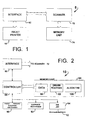
- FIG. 1 is a block diagram of a preferred embodiment of copier;
- FIG. 2 is a block diagram of a high speed inkjet printer forming part of the copier of FIG. 1, illustrating the main hardware components of the printer;
- FIG. 3 is a fragmentary pictorial view of the copier of FIG. 1, illustrating its high speed inkjet printer;
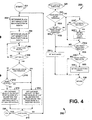
- FIG. 4 is a flow chart showing the steps performed by the print controller of FIG. 2 in printing a swath of information on a printing media;
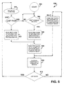
- FIG. 5 is a flowchart showing the steps performed by the print controller of FIG. 2 when executing a density calculation subroutine;
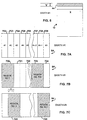
- FIG. 6 is a plan view of a medium sheet illustrating diagrammatically a high density swath of ink droplets ejected thereon by the high speed inkjet printer of FIG. 3;
- FIG. 7A is a diagrammatic view of a swath profile of the high density swath of FIG. 6, illustrating swath profile partitions;
- FIGS. 7B-C are diagrammatic views of the swath profile partitions of FIG. 7A segmented into a plurality of overlapping density regions; and
- FIG. 8 is a perspective view of another embodiment of colour copier.
-
- Referring now to the drawings and more particularly to FIGS 1-3 thereof, there is shown an embodiment of a full colour copier 8. The copier 8 utilizes a wet ink process for reproducing text and object images.
- The copier 8 includes a
scanner 72 having amemory unit 74 for scanning and storing document images to be printed. The combination of thescanner 72 and its associatedmemory unit 74 facilitates rapid reproduction of the document images to be printed as the document images to be printed need only to be scanned a single time. - In order to reproduce a hard copy of the document images stored in the
memory unit 74, the copier 8 also includes a high speed, fullcolor inkjet printer 10 that is coupled electrically to thescanner 72 via aninterface unit 62. Theinkjet printer 10, via theinterface unit 62, responds to print commands from thescanner 72 to print various full color as well as black print images in the form of objects or textual information which have been stored temporarily in thememory unit 74 for copying purposes. FIG. 3 is a fragmentary perspective view showing an exemplary embodiment of the copier 8 illustrating theprinter 10 portion with its housing 28 andcontrol panel 20. Theprinter 10 is shown with itscover 22 in an open position to help illustrate various major mechanical components of the printing system. - Considering now the
printer 10 in greater detail with reference to FIG. 2-3, theprinter 10 generally includes aprint controller 88 having an associated memory unit 64. Theprint controller 88 responds to the print commands send by thescanner 72 by receiving and storing the document images to be printed in adata area 66 of the memory unit 64. The memory unit 64 also includes adriver routine area 68 for storing routines that control the mechanical apparatuses forming part of theprinter 10. The mechanical apparatuses that form part of theprinter 10, that will be described hereinafter in greater detail, include a sheet feeding and stackingmechanism 90, acarriage mechanism 92 for driving movably acarriage unit 16 having a set of stalls for receiving one ormore print cartridges 18. Each print cartridge includes a plurality of inkjet nozzles, such as aninkjet nozzle 92. For clarity purposes FIG. 3 illustrates only onecartridge 18, with the remaining three stalls or bays being empty and marked with reference characters in parentheses thus: (18C), (18M), and (18Y) are the empty stalls for the cyan, magenta and yellow print cartridges. - In operation, the high
speed inkjet printer 10 responds to commands from thescanner 72 by printing full color or black print images on a sheet ofpaper 12 or other form of printing medium, such as a transparency which is retrieved mechanically from a medium supply tray 15 that holds a given amount of the printing medium. The given amount of printing medium that can be held by the supply tray 15 varies between a single sheet, such as thesheet 12, to a predetermined maximum quantity. - The
printer 10 operates in a single pass printing mode to cause one or more swaths of ink droplets, such as a swath 84 (FIG. 6), to be ejected on to theprinting medium 12 to form a desired image. Theswath 84 is formed in a pattern of individual dots at particular locations of an array defined for theprinting medium 12. The locations are conveniently visualized as being small dots in a matrix array. The locations of the individual ink droplets are known as "dot positions," or "pixels." Theprint carriage 16 having one or more print cartridges thereon, is supported from below on aslide rod 24 that permits thecarriage 16 to move along a rectilinear path of travel whose direction is indicated generally at 86. - The path of travel followed by the
print carriage 16 is traverse to the path of travel followed by thesheet 12 as it passes through a print zone 14. In this regard, when a print operation is initiated by thescanner 72, thecontroller 88 responds causing the sheetfeeding stacking mechanism 90 to retrieve and move thesheet 12 from the supply tray 15 along a medium path of travel within theprinter 10 into the print zone 14. When thesheet 12 reaches the print zone 14, thesheet 12 is stopped temporarily for printing purposes. When thesheet 12 stops in its path of travel, thecarriage mechanism 92 causes thecarriage 16 to scan across thesheet 12 allowing the print cartridges, such as theprint cartridge 18 to eject drops of ink at appropriate times pursuant to the command of theprint controller 88, wherein the timing of the application of the ink drops onto thesheet 12 corresponds to the pattern of pixels of the image being printed. - After the
first swath 84 of ink droplets is deposited onto thesheet 12, a stepper motor in combination with a set of feed rollers (not shown) forming part of the sheetfeeding stacking mechanism 90 cause thesheet 12 to be incrementally shifted or moved along its path of travel to a next printing position within the print zone 14. When thesheet 12 comes to rest at the next position in the print zone 14, thecarriage 16 is scanned across thesheet 12 in an opposite direction along its path of travel for printing a next swath of ink. When thesheet 12 has been advanced through each of its printing positions in the print zone 14 so that printing of the desired information is completed, thesheet 12 is moved from the print zone to anoutput tray 17. In this manner, the smearing of wet ink on thesheet 12 is prevented. - Considering now the operation of the
printer 10 in greater detail with reference to FIGS. 4-7, when theprint head carriage 16 sweeps across theprinting medium 12, the various ones of the ink jet nozzles on theprint cartridges 18 eject ink to form a column of ink droplets whose height (x) is determined by the configuration and number of ink jet nozzles disposed on theprint cartridge 18. In a 300 dot per inch print head, the height of the column is expressed as a function of the number of rows of dots, which in the preferred embodiment is about N rows, where N is between about 104 and about 150. The width (y) of the column is determined by the length of the path of travel followed by the carriage as it travels across thepaper medium 12. The resulting columns of ink droplets printed in one sweep of thecarriage 16 across the medium 12 is commonly referred to a swath. - To print a given object or textual information on the medium 12, the
scanner 72 scans a document to be copied and stores its textual and object images in thememory unit 74. Once the document images to be printed have been stored in thememory unit 74, thescanner 72 causes a print command to be sent to theprinter 10. The object or textual information to be printed is also sent to theprinter 10 and is stored in thedata area 66 of the memory unit 64 as a plot profile file. - The
controller 88 causes the received data to the stored in the form of plot profile files. Thecontroller 88 while storing the received data utilizes acontrol algorithm 100 to determine the speed at which the object or textual information is to be printed. More particularly, theprinter 10 has an optimum maximum printing speed wherein thecarriage 16 travels along its rectilinear path of travel at a rate of about 1000 millimeters per second while firing the various inkjet nozzles at about a 12 Kilohertz rate. The carriage velocity and the firing rate of the inkjet nozzles determine the maximum throughput of theprinter 10 when ink drop density on the medium is at a nominal level. However, when the ink drop density increases to a maximum level, theprinter 10, under the control of thecontroller 88 and thealgorithm 100, reduces its carriage velocity and nozzle firing rate intra page to allow sufficient time for the ink deposited onto theprinting media 12 to dry. Stated otherwise, as will be explained hereinafter in greater detail, whenever the controller determines that ink drop densities have exceeded certain predetermined threshold levels in any given swath of information to be printed, thecontroller 88 causes that particular swath to be printed at a slower rate by reducing the velocity of thecarriage unit 16 and by reducing the time between the firing of the nozzles. - Considering now the operation of the
printer 10 in greater detail with reference to FIGS. 4-7, theprinter 10 operates in two high density print modes. A first high density print mode has a carriage velocity of between about 1.0 meters per second and about 0.5 meters per second. A second high density print mode has a carriage velocity of between about 0.5 meters per second and about 0.25 meters per second. Under the control of thecontroller 88 and the associatedcontrol program 100, theprinter 10 switches intra page on a swath by swath basis between these different high density printing modes depending upon the black ink droplet densities and the colorant ink droplet densities required by the individual ones of the swaths as will be explained hereinafter in greater detail. - In order to switch printing speeds from swath to swath on an intra page basis, the
controller 88 operating under the commands of thealgorithm 100, divides the image to be printed into one or more swaths and further divides each swath into a given number of partitions, such as an N number of partitions 702-709 as generally indicated in FIG. 7A. Each partition is n columns wide by m rows high. - For facilitating density calculations, the partitions are arranged in regions, such as regions 720-724 where each region is composed of two overlapping partitions 2n columns wide and m rows high. For example, as best seen in FIGS 7B-C, the first and
second regions swath 84 have a common overlapping area occupied bypartition 703 whose relative location is indicated generally at A. - The value of n ranges between 16 columns and 512 columns. A more preferred range of n is between 32 columns and 256 columns and the most preferred value for n is 128 columns. The value of m ranges between 2 rows and 128 rows. A more preferred range of m is between 4 rows and 64 rows, and the most preferred value for n is 32 rows.
- As will be explained hereinafter in greater detail, a
density subroutine 200 determines the black dot density and the combined color dot density in each partition of each swath. The black dot density is computed utilizing equation 1:
and where the black dot density range is ( 0% <= Kdens <= 100%) - The combined color dot density is computed utilizing equation 2:
and where the color dot density range is ( 0% <= Cdens <=300% ) - The control or
density algorithm 200 then analyzes the black and combined color dot densities within the rows to be printed and in overlapping regions having a width of 2n columns to establish the printing speed for each individual swath in the image to be printed so that the print sweep velocity is reduced when the black dot density in one or more regions of a given swath exceeds a fixed threshold density level and the color dot density level within all the other regions in the given swath are below the fixed threshold level. Table No. 1 is a look up table thecontroller 88 utilizes in determining whether to advance thecarriage 16 at its high speed textual rate or at its lower high speed object or image rate.Retardation Algorithm Threshold Values Threshold
ValuePreferred
Value RangeMore Preferred
Value RangeMost Preferred
Value RangeBlack Only 20%-100% 40%-90% 60% Black/ Color 20%-100% 40%-90% 70% Color 0%-300% 30%-200% 70% Color Hue 0%-100% 20%-100% 50% - To illustrate for example the application of Table No. 1, when the black dot density is less than 60%, the
controller 88 causes thecarriage 16 to sweep at its high speed textual rate of about 0.25 seconds per sweep with a pen firing rate of about 12 Kilo hertz and at about 0.50 seconds per sweep with a pen firing rate of about 6 Kilo hertz when the black dot density is equal to or greater than 60%. - From the foregoing, it should be understood by those skilled in the art that the
algorithm 100 examines color density as a factor because a sweep velocity reduction may cause a color hue shift, which in turn, will effect print quality. Therefore, color hue shift is minimized in regions where color and black are mixed. In short, print speed reduction is avoided when a sweep contains sufficiently dense color in regions with low black dot density. - Considering now the steps performed by the
controller 88 carrying out thealgorithm 100 with reference to FIGS. 4-5, in this exemplary embodiment thecontroller 88 begins thealgorithm 100 at astart command step 502 when power is applied to thecontroller 88. Thecontroller 88 then enters an idle mode at adecision step 504 waiting for thescanner 72 to send a print command. - When the
scanner 72 initiates a print command, theprinter control program 100 advances to acommand step 506 and reads the first page of information to be printed dividing the information into a series of profile or swath files. Instep 508 the control program causes thecontroller 88 to divide the first swath, such as theswath 84, into N number of partitions, where each partition is n columns wide and m rows in height. - Next at a
command step 510 the control program causes thecontroller 88 to allocate the partitions, such as the partitions 702-709 into a plurality of overlapping regions, where each region comprises twice the number of columns in any given partition. Thecontrol program 100 then steps to adecision command 512 to determine whether the partitioned swath was the last swath relative to the total number of swaths on the page of information to be printed. - If the swath was not the last swath to be printed, the
control program 100 advances to a command step 514 that causes the next swath to be divided into N number of partitions in the same manner as described previously. Once the next swath has been partition, thecontroller 88 steps to theallocation step 510 and proceeds as described previously. - If the swath was the last swath to be printed, the
control program 100 advances to a call command that calls aDENSITY CALCULATION subroutine 200 that will be described hereinafter in greater detail. After theDENSITY CALCULATION subroutine 200 is executed, the control program advances to adecision command 518 to determine whether the page of information printed was the last page of information associated with the print command sent by thescanner 72. In this regard, if there are no more pages of information to be printed, the control program proceeds to the idle mode at thedecision command 504 to wait for another print command from thescanner 72. - In
step 518 if it is determined that additional pages of information need to be printed, the control program goes to aread command step 522 and causes the next page of information to be retrieved from the memory unit 64 and divides it into one or more profile swath files. Thecontrol program 100 then returns to thecommand step 508 and proceeds as described previously. - Considering now the
DENSITY CALCULATION subroutine 200 in greater detail with reference to FIG. 4, from thecall command step 516 thecontrol program 100 proceeds to subroutine 200 at astart step 201 and immediately advances to acommand step 202 to determine the black dot density for each partition in a current swath, such as theswath 84. Next the control program advances to anothercommand step 204 to determine the color dot density for each partition in the current swath. - After the black and color dot densities have been determined, the
subroutine 200 advances to acall step 206 that causes aSWEEP RATE subroutine 250 to be executed. TheSWEEP RATE subroutine 250 will be described hereinafter in greater detail. TheSWEEP RATE subroutine 250 helps facilitating establishing the velocity rate of thecarriage 16 and the time delay between the firing of theprint cartridges 18 and their associated nozzles. - After the
SWEEP RATE subroutine 250 is executed, subroutine control returns to adecision step 208 to determine whether the last region has been analyzed. If the last region has not been analyzed the program goes to thecall step 206 and proceeds as described previously. If the last region was analyzed the program goes to a decision step210 that determines whether the maximum color is greater than the color hue threshold level for the given sweep. If the maximum color is greater than the color hue threshold level, the program proceeds to acommand step 214 that set the carriage velocity to a maximum printing rate of x+w millimeters per second and sets the pen firing rate to a maximum pen firing rate of Z times per second. - If at
step 210 it is determined that the maximum color is not greater than the color hue threshold level, the program proceeds to adecision step 212 that determines whether the slow sweep flag has been set when the program executed theSWEEP RATE subroutine 250 as will be described hereinafter in greater detail. - If at
step 212 it is determined that the slow sweep flag has not been set, the program goes to thecommand step 214 and proceeds as described previously. If atstep 212 it is determined that the slow sweep flag was set, the program advances to acommand step 216 that causes the carriage velocity to be set to the slow rate of x millimeters per second and the pen firing rate set to a slow firing rate of R times per second. - After the either of the command steps 214 and 216 have been executed, the program advances to a
decision step 218 to determine whether all of the sweeps on the first page of information to be printed have been analyzed. If all of the swaths have not been analyzed, the program goes to thecommand step 202 and proceeds as described previously. If the last swath has been analyzed, the program goes to anend step 220 that causes the program to return to step 518 as best seen in FIG. 5. - In the preferred embodiment of the present invention, the maximum velocity of x+w millimeters per second is only limited by the maximum velocity that the carriage can travel. This maximum velocity is about 1250 millimeters per second. A more preferred maximum velocity is about 1125 millimeters per second, and the most preferred maximum velocity is about 1000 millimeters per second. The delay time between pen firings is set to about 12 Khz rate at
step 214. - In the preferred embodiment of the present invention, the delay times of Z and R are substantially different from one another. In this regard, the delay time Z is at about a 6.0 Kilohertz rate while the delay time R is at about a 12 Kilohertz rate. The delay times of Z and R should not be confused with the firing cycle time of the print head cartridge which is fixed at about 2 microseconds regardless of the delay times between pen firings.
- Considering now the
SWEEP RATE subroutine 250 in greater detail with reference to FIG. 4, the SWEEP RATE subroutine is accessed from thecall command step 206 and begins at astart command 300. The subroutine then continues to adecision step 302 that determines whether the color density level in the current region is greater than the color density threshold level. If the color density is greater than the color threshold level, the subroutine advances to anotherdecision step 304 to determine whether the black dot density of the current region is greater than the black with color threshold level. Atstep 302 if a determination is made that the color density is not greater than the color threshold level, thesubroutine 250 proceeds to a decision step 320. - Considering again the
step 304, if at step 304 a determination is made that the black dot density is not greater than the black with color threshold level, the subroutine advances to the determination step 320 that will be described hereinafter. - If at step 304 a determination is made that the black density is greater than the black with color threshold level, the subroutine proceeds to the command step 306 and sets a SLOW SWEEP condition flag that will be utilized subsequently to determine whether a fast or slow sweep rate will be applied to the current swath under analysis as will be described in greater detail.
- After the subroutine determines at
step 302 that the color density of the current region is not greater than the color threshold level, thesubroutine 250 advances to the decision step 320 as mentioned previously. At step 320 a determination is made regarding whether the color density of the current region is greater than a maximum color density level. If this condition is true, the subroutine goes to a command instruction step 322 that causes a condition flag to be set to indicate that maximum color is the color density. From step 322, the subroutine advances to adecision step 324 that will be described. - If the condition in step 320 is not true, the subroutine advance directly to the
decision step 324, where a determination is made whether the black dot density in the current region is greater than the black only threshold level. If the black dot density in the current region is not greater than the black only threshold level, the subroutine advances to the command step 306 and sets the SLOW SWEEP condition. After the SLOW SWEEP condition is set at step 306, the subroutine goes to aRETURN step 338 that returns the program to step 208 to examine another region in the swath. - Considering again the
decision step 324, if the black dot density in the current region is greater than the black only threshold level, the subroutine proceed to a determination step 326 that determines whether the color dot density in the current region is greater than the maximum color level. - In decision step 326 if a determination is made that the color dot density is not greater than the maximum color level, the subroutine goes to the
return step 338 that returns the program to step 208 as described previously. Otherwise, the next step is a command step 328 where thecontroller 88 sets a flag to indicate that maximum color is maximum density. After executing the command step 328 the program advances to thereturn step 338 and proceeds as described previously. - From the foregoing it should be understood by those skilled in the art that the
printer 10 operates in two high speed intra page printing modes that switch from one to another under the control of thecontroller 88 depending upon the ink drop density from swath to swath. The high speed high density rate is about one half the high speed low density rate relative to both the carriage velocity and the firing frequency rate of the individual nozzles. - It should also be understood by those skilled in the art that although the firing frequency of the individual nozzles is changed from one frequency to another frequency, the firing time of the individual nozzles is not changed but remains constant at both the high speed high density rate and the high speed low density rate. In this manner, the large volumes of ink that must be ejected in the high speed high density are precisely measured giving each nozzle an adequate period of time to refill and settle from a previous firing. Thus, not only is ink pen starvation is avoided but such additional time allocations between pen firing cycles helps reduce droplet trajectory errors, and significantly improves image quality by substantially reducing fuzzy text edges.
- Referring now to the drawings and more particularly to FIG. 8, there is shown an
full color copier 108 which is constructed in accordance with the present invention. Thecopier 108 is substantially similar to the copier 8 and includes aprinter 110 and ascanner 172 having acontrol panel 120. As best seen in FIG. 8, the only difference between the copier 8 and thecopier 108 is the physical configuration of thecontrol panel 120 and the physical arrangement of theprinter 110 and thescanner 172. - While a particular embodiment of the present invention has been disclosed, it is to be understood that various different modifications are possible. For example, in the preferred embodiment of the present invention the width of each partition in a given swath is greater in dimension than the number of rows in each partition. It is contemplated that the width of each partition in a given swath may be substantially less or equal in dimension to the number of rows in each partition. There is no intention, therefore, of limitations to the exact abstract or disclosure herein presented.
Claims (9)
- A colour copier (8) comprising:wherein the printing speed of the printer (10) is operable to switch from swath to swath on an intra page basis between a relatively higher speed textual rate and a relatively lower speed image rate, depending upon determined black ink droplet density level or levels and colorant ink droplet density level or levels within each one of said plurality of swaths.a scanner (72) for reading a document to be copied; andan inkjet printer (10) responsive to the scanner (72) for printing on a sheet of print media (12) at least one copy of the document image;said at least one copy of the document image being formed by a plurality of swaths of black ink droplets and colorant ink droplets distributed in various swath densities on the print media (12);
- A colour copier (8) according to claim 1, wherein said inkjet printer (10) includes:wherein said relatively higher speed textual rate is able to facilitate the printing of individual ones of the swaths each having a black ink droplet density exceeding a given threshold level in at least one region of the individual swath and a colorant ink droplet density not exceeding said given threshold level in all the remaining regions of the individual swath; anda carriage unit (16) with at least one print head (94) mounted thereon for printing on the sheet of print media (12) the at least copy of the scanned document image;velocity control means (88, 100) coupled to the carriage unit (16) for causing the carriage unit to advance along a rectilinear path of travel at one of said two different velocities during the formation of the individual ones of said plurality of swaths forming the copy of the scanned document image;
wherein said relatively lower speed image rate is able to facilitate the printing of other individual ones of the swaths each having a colorant ink droplet density exceeding said given threshold level in at least one region of the other individual swath regardless of the black ink droplet density in the other individual swath. - A copier (8) according to claim 2, wherein said relatively higher speed textual rate is between about 0.75 meters per second and about 1.50 meters per second; and wherein said relatively lower speed image rate is between about 0.25 meters per second and about 0.75 meters per second.
- A copier (8) according to claim 3, wherein said textual rate is about 1.00 meters per second; and wherein said image rate is about 0.50 meters per second.
- A copier (8) according to claim 2, 3 or 4, comprising:a firing rate control arrangement (88,200) for causing said print head (94) to eject black ink droplets and colorant ink drops at one of two different rates during the formation of individual ones of the plurality of swaths forming the image;one of said rates being a first firing rate for facilitating the printing of each individual one of the swaths having a black ink droplet density exceeding said given threshold level in at least one region of the swath and a colorant ink droplet density not exceeding said given threshold level in all the remaining regions of the swath;another one of said rates being a second firing rate for facilitating the printing of each individual one of the swaths having a colorant ink droplet density exceeding said given threshold level in at least one region of the swath regardless of the black ink droplet density in said swath.
- A copier (8) according to claim 5, wherein said first firing rate is between about 1000 ejections per second and about 10000 ejections per second.
- A copier (8) according to claim 6, wherein a first firing rate is about 6000 ejections per second.
- A method of printing a color image on a sheet of print medium (12), the image being formed by a plurality of swaths of black ink droplets and colorant ink droplets distributed in various swath densities on the print medium (12), comprising:ejecting the black ink droplets and the colorant ink droplets onto the print medium (12) in the various swath densities;using a print head (94) to facilitate the formation of images of the sheet of print medium (12):moving said print head (94) traversely to the print medium (12) along a rectilinear path of travel so that the plurality of swaths of black ink droplets and the colorant ink droplets ejected by said print head (94) form the image as the sheet of print medium (12) moves traversely to said print head (94) along another rectilinear path of travel;advancing the print head (94) along said rectilinear path of travel at one of two different velocities during the formation of the individual ones of the plurality of swaths forming the image;one of said velocities being a first textual velocity for facilitating the printing of each individual one of the swaths having a black ink droplet density exceeding a given threshold level in at least one region of the swath and a colorant ink droplet density not exceeding said given threshold level in all the remaining regions of the swath;another one of said velocities being a second image velocity for facilitating the printing of each individual one of the swaths having a colorant ink droplet density exceeding said given threshold level in at least one region of the swath regardless of the black ink droplet density in said swath.
- A printing method according to claim 8, comprising:ejecting black ink droplets and colorant ink drops at one of two different rates during the formation of individual ones of the plurality of swaths forming the image;one of said rates being a first firing rate for facilitating the printing of each individual one of the swaths having a black ink droplet density exceeding said given threshold level in at least one region of the swath and a colorant ink droplet density not exceeding said given threshold level in all the remaining regions of the swath;another one of said rates being a second firing rate for facilitating the printing of each individual one of the swaths having a colorant ink droplet density exceeding said given threshold level in at least one region of the swath regardless of the black ink droplet density in said swath.
Applications Claiming Priority (2)
| Application Number | Priority Date | Filing Date | Title |
|---|---|---|---|
| US901464 | 1992-06-19 | ||
| US08/901,464 US6012792A (en) | 1997-07-28 | 1997-07-28 | Copier having full color high speed inkjet printer with two intra page printing speeds for controlling ink drying time for images having densely inked areas |
Publications (2)
| Publication Number | Publication Date |
|---|---|
| EP0894639A1 EP0894639A1 (en) | 1999-02-03 |
| EP0894639B1 true EP0894639B1 (en) | 2002-09-25 |
Family
ID=25414238
Family Applications (1)
| Application Number | Title | Priority Date | Filing Date |
|---|---|---|---|
| EP98305327A Expired - Lifetime EP0894639B1 (en) | 1997-07-28 | 1998-07-03 | Colour copier |
Country Status (3)
| Country | Link |
|---|---|
| US (1) | US6012792A (en) |
| EP (1) | EP0894639B1 (en) |
| DE (1) | DE69808198T2 (en) |
Families Citing this family (18)
| Publication number | Priority date | Publication date | Assignee | Title |
|---|---|---|---|---|
| US6452618B1 (en) * | 1997-12-22 | 2002-09-17 | Hewlett-Packard Company | Carriage velocity control to improve print quality and extend printhead life in ink-jet printer |
| US6588869B1 (en) * | 1998-11-05 | 2003-07-08 | Gateway, Inc. | Front accessible, stackable, printer/scanner/fax |
| US6359642B1 (en) * | 1999-01-27 | 2002-03-19 | Hewlett-Packard Company | Printer control system |
| US6217150B1 (en) * | 1999-06-11 | 2001-04-17 | Lexmark International, Inc. | Method of printing with an ink jet printer using multiple carriage speeds |
| US6302505B1 (en) * | 2000-07-28 | 2001-10-16 | Hewlett-Packard Company | Printing system that utilizes continuous and non-continuous firing frequencies |
| JP4034930B2 (en) * | 2000-09-29 | 2008-01-16 | 富士フイルム株式会社 | Image data conversion device, image data conversion program storage medium, and image data reconversion program storage medium |
| US6585342B1 (en) * | 2000-11-13 | 2003-07-01 | Xerox Corporation | Object oriented images forming |
| US6655782B2 (en) * | 2001-10-31 | 2003-12-02 | Hewlett-Packard Development Company, Lp. | Printer device and method |
| US6695426B2 (en) | 2002-02-11 | 2004-02-24 | Lexmark International, Inc. | Ink jet printer improved dot placement technique |
| US20050140708A1 (en) * | 2003-08-05 | 2005-06-30 | Christian Barckhahn | Printer device and method |
| GB2429093B (en) * | 2005-08-08 | 2011-04-13 | Inca Digital Printers Ltd | Inkjet printer control |
| US20090085944A1 (en) * | 2007-08-31 | 2009-04-02 | Keeton Mark E | Printer and method of combining inkjet printing with thermal printing |
| JP5616594B2 (en) * | 2008-07-04 | 2014-10-29 | 理想科学工業株式会社 | Printing device |
| JP2011161752A (en) * | 2010-02-09 | 2011-08-25 | Seiko Epson Corp | Printer |
| US9757955B2 (en) * | 2015-12-09 | 2017-09-12 | Funai Electric Co., Ltd. | Imaging apparatus and method of using colorant density for reducing printing defects |
| US10560584B2 (en) | 2015-12-11 | 2020-02-11 | Hewlett-Packard Development Company, L.P. | Density classifiers based on plane regions |
| US11040329B2 (en) | 2017-03-17 | 2021-06-22 | Hewlett-Packard Development Company, L.P. | Density classifiers based on plane regions |
| JP7094812B2 (en) * | 2018-07-17 | 2022-07-04 | キヤノン株式会社 | Recording device, recording method, and program |
Family Cites Families (15)
| Publication number | Priority date | Publication date | Assignee | Title |
|---|---|---|---|---|
| CA1127227A (en) * | 1977-10-03 | 1982-07-06 | Ichiro Endo | Liquid jet recording process and apparatus therefor |
| DE3412531A1 (en) * | 1984-04-04 | 1985-10-17 | Olympia Werke Ag, 2940 Wilhelmshaven | Ink jet printing mechanism for multicolour printing on a recording medium |
| JP2652405B2 (en) * | 1988-04-26 | 1997-09-10 | キヤノン株式会社 | Ink jet recording device |
| US4864328A (en) * | 1988-09-06 | 1989-09-05 | Spectra, Inc. | Dual mode ink jet printer |
| SG44724A1 (en) * | 1989-01-28 | 1997-12-19 | Canon Kk | Ink jet recording method and color ink jet recording device for practising the same |
| DE69232977T2 (en) * | 1991-07-30 | 2003-11-06 | Canon Kk | Ink jet recording apparatus and method |
| JPH0615817A (en) * | 1992-06-30 | 1994-01-25 | Fuji Xerox Co Ltd | Ink jet recording apparatus |
| US5414453A (en) * | 1993-04-30 | 1995-05-09 | Hewlett-Packard Company | Use of a densitometer for adaptive control of printhead-to-media distance in ink jet printers |
| US5489926A (en) * | 1993-04-30 | 1996-02-06 | Hewlett-Packard Company | Adaptive control of second page printing to reduce smear in an inkjet printer |
| US5455610A (en) * | 1993-05-19 | 1995-10-03 | Xerox Corporation | Color architecture for an ink jet printer with overlapping arrays of ejectors |
| US5469196A (en) * | 1993-06-30 | 1995-11-21 | Hewlett-Packard Company | Print material variable support mechanism |
| JPH0740549A (en) * | 1993-07-26 | 1995-02-10 | Canon Inc | Ink jet recording and device |
| US5714990A (en) * | 1995-01-03 | 1998-02-03 | Xerox Corporation | Optimizing printing speed and managing printed sheet ejection based on image density and method of determining density |
| US5527121A (en) * | 1995-02-15 | 1996-06-18 | Hewlett-Packard Company | Printhead carriage control method and apparatus for achieving increased printer throughput |
| US5771338A (en) * | 1996-09-26 | 1998-06-23 | Hewlett-Packard Company | Error diffusion architecture with simultaneous print and store data paths for converting a scanned image into multiple copies of a printed image |
-
1997
- 1997-07-28 US US08/901,464 patent/US6012792A/en not_active Expired - Lifetime
-
1998
- 1998-07-03 DE DE69808198T patent/DE69808198T2/en not_active Expired - Lifetime
- 1998-07-03 EP EP98305327A patent/EP0894639B1/en not_active Expired - Lifetime
Also Published As
| Publication number | Publication date |
|---|---|
| DE69808198D1 (en) | 2002-10-31 |
| DE69808198T2 (en) | 2003-04-30 |
| US6012792A (en) | 2000-01-11 |
| EP0894639A1 (en) | 1999-02-03 |
Similar Documents
| Publication | Publication Date | Title |
|---|---|---|
| EP0894639B1 (en) | Colour copier | |
| US5903290A (en) | Simultaneously printing with different sections of printheads for improved print quality | |
| EP0771661B1 (en) | Use of a densitometer for adaptive control of printer heater output to optimize drying time for different print media | |
| US5414453A (en) | Use of a densitometer for adaptive control of printhead-to-media distance in ink jet printers | |
| US6084604A (en) | Color ink jet recording method and apparatus using black ink and color-mixed black ink | |
| JP3678447B2 (en) | Ink-jet printing method and apparatus | |
| CA2164891C (en) | Optimizing printing speed and managing printed sheet ejection based on image density and method of determining density | |
| US6547354B1 (en) | Printing system that utilizes print masks with resolutions that are non-integral multiples of each other | |
| EP1225757B1 (en) | Printing method and apparatus | |
| JP2000079681A (en) | Recorder, control method therefor and computer readable memory | |
| US7083255B2 (en) | Ink jet printing apparatus and ink jet printing method | |
| EP1038688B1 (en) | Mixing overprinting and underprinting of inks in an inkjet printer to speed up the dry time of black ink without undersirable hue shifts | |
| JPH11207948A (en) | Recording device and recording control method | |
| EP0517520B1 (en) | Ink-jet recording method and ink-jet recording apparatus | |
| EP0817114B1 (en) | Dot application scheduling in inkjet printers | |
| JP3239367B2 (en) | Inkjet recording method and recording apparatus | |
| WO2015167452A1 (en) | Image content based spit bars | |
| US6174037B1 (en) | Multiple pass ink jet printer with optimized power supply | |
| JP2000025210A (en) | Recorder, control method therefor and computer readable memory | |
| US6646756B2 (en) | Printing apparatus and method which controls driving of a printing head according to received data | |
| US20020186276A1 (en) | Printing apparatus and control method therefor | |
| JP4402911B2 (en) | Inkjet recording apparatus and method | |
| JPH06135014A (en) | Ink jet reocrding method | |
| US6685291B1 (en) | Printing apparatus and printing method | |
| JP2000025208A (en) | Recorder, control method thereof and computer readable memory |
Legal Events
| Date | Code | Title | Description |
|---|---|---|---|
| PUAI | Public reference made under article 153(3) epc to a published international application that has entered the european phase |
Free format text: ORIGINAL CODE: 0009012 |
|
| AK | Designated contracting states |
Kind code of ref document: A1 Designated state(s): DE FR GB |
|
| AX | Request for extension of the european patent |
Free format text: AL;LT;LV;MK;RO;SI |
|
| 17P | Request for examination filed |
Effective date: 19990329 |
|
| 17Q | First examination report despatched |
Effective date: 19990901 |
|
| AKX | Designation fees paid |
Free format text: AT BE CH CY DE DK ES FI FR GB GR IE IT LI LU MC NL PT SE |
|
| AXX | Extension fees paid |
Free format text: AL;LT;LV;MK;RO;SI |
|
| RAP1 | Party data changed (applicant data changed or rights of an application transferred) |
Owner name: HEWLETT-PACKARD COMPANY, A DELAWARE CORPORATION |
|
| GRAG | Despatch of communication of intention to grant |
Free format text: ORIGINAL CODE: EPIDOS AGRA |
|
| GRAG | Despatch of communication of intention to grant |
Free format text: ORIGINAL CODE: EPIDOS AGRA |
|
| GRAH | Despatch of communication of intention to grant a patent |
Free format text: ORIGINAL CODE: EPIDOS IGRA |
|
| GRAH | Despatch of communication of intention to grant a patent |
Free format text: ORIGINAL CODE: EPIDOS IGRA |
|
| GRAA | (expected) grant |
Free format text: ORIGINAL CODE: 0009210 |
|
| AK | Designated contracting states |
Kind code of ref document: B1 Designated state(s): DE FR GB |
|
| REG | Reference to a national code |
Ref country code: GB Ref legal event code: FG4D |
|
| REF | Corresponds to: |
Ref document number: 69808198 Country of ref document: DE Date of ref document: 20021031 |
|
| ET | Fr: translation filed | ||
| PLBE | No opposition filed within time limit |
Free format text: ORIGINAL CODE: 0009261 |
|
| STAA | Information on the status of an ep patent application or granted ep patent |
Free format text: STATUS: NO OPPOSITION FILED WITHIN TIME LIMIT |
|
| 26N | No opposition filed |
Effective date: 20030626 |
|
| REG | Reference to a national code |
Ref country code: GB Ref legal event code: 732E Free format text: REGISTERED BETWEEN 20120329 AND 20120404 |
|
| PGFP | Annual fee paid to national office [announced via postgrant information from national office to epo] |
Ref country code: FR Payment date: 20120731 Year of fee payment: 15 |
|
| PGFP | Annual fee paid to national office [announced via postgrant information from national office to epo] |
Ref country code: GB Payment date: 20130626 Year of fee payment: 16 |
|
| PGFP | Annual fee paid to national office [announced via postgrant information from national office to epo] |
Ref country code: DE Payment date: 20130621 Year of fee payment: 16 |
|
| REG | Reference to a national code |
Ref country code: FR Ref legal event code: ST Effective date: 20140331 |
|
| PG25 | Lapsed in a contracting state [announced via postgrant information from national office to epo] |
Ref country code: FR Free format text: LAPSE BECAUSE OF NON-PAYMENT OF DUE FEES Effective date: 20130731 |
|
| REG | Reference to a national code |
Ref country code: DE Ref legal event code: R119 Ref document number: 69808198 Country of ref document: DE |
|
| GBPC | Gb: european patent ceased through non-payment of renewal fee |
Effective date: 20140703 |
|
| PG25 | Lapsed in a contracting state [announced via postgrant information from national office to epo] |
Ref country code: DE Free format text: LAPSE BECAUSE OF NON-PAYMENT OF DUE FEES Effective date: 20150203 |
|
| REG | Reference to a national code |
Ref country code: DE Ref legal event code: R119 Ref document number: 69808198 Country of ref document: DE Effective date: 20150203 |
|
| PG25 | Lapsed in a contracting state [announced via postgrant information from national office to epo] |
Ref country code: GB Free format text: LAPSE BECAUSE OF NON-PAYMENT OF DUE FEES Effective date: 20140703 |