EP0894210B1 - Variator control system - Google Patents
Variator control system Download PDFInfo
- Publication number
- EP0894210B1 EP0894210B1 EP97915588A EP97915588A EP0894210B1 EP 0894210 B1 EP0894210 B1 EP 0894210B1 EP 97915588 A EP97915588 A EP 97915588A EP 97915588 A EP97915588 A EP 97915588A EP 0894210 B1 EP0894210 B1 EP 0894210B1
- Authority
- EP
- European Patent Office
- Prior art keywords
- pressure
- fluid
- variator
- roller
- hydraulic
- Prior art date
- Legal status (The legal status is an assumption and is not a legal conclusion. Google has not performed a legal analysis and makes no representation as to the accuracy of the status listed.)
- Expired - Lifetime
Links
Images


Classifications
-
- F—MECHANICAL ENGINEERING; LIGHTING; HEATING; WEAPONS; BLASTING
- F16—ENGINEERING ELEMENTS AND UNITS; GENERAL MEASURES FOR PRODUCING AND MAINTAINING EFFECTIVE FUNCTIONING OF MACHINES OR INSTALLATIONS; THERMAL INSULATION IN GENERAL
- F16H—GEARING
- F16H15/00—Gearings for conveying rotary motion with variable gear ratio, or for reversing rotary motion, by friction between rotary members
- F16H15/02—Gearings for conveying rotary motion with variable gear ratio, or for reversing rotary motion, by friction between rotary members without members having orbital motion
- F16H15/04—Gearings providing a continuous range of gear ratios
- F16H15/06—Gearings providing a continuous range of gear ratios in which a member A of uniform effective diameter mounted on a shaft may co-operate with different parts of a member B
- F16H15/32—Gearings providing a continuous range of gear ratios in which a member A of uniform effective diameter mounted on a shaft may co-operate with different parts of a member B in which the member B has a curved friction surface formed as a surface of a body of revolution generated by a curve which is neither a circular arc centered on its axis of revolution nor a straight line
- F16H15/36—Gearings providing a continuous range of gear ratios in which a member A of uniform effective diameter mounted on a shaft may co-operate with different parts of a member B in which the member B has a curved friction surface formed as a surface of a body of revolution generated by a curve which is neither a circular arc centered on its axis of revolution nor a straight line with concave friction surface, e.g. a hollow toroid surface
- F16H15/38—Gearings providing a continuous range of gear ratios in which a member A of uniform effective diameter mounted on a shaft may co-operate with different parts of a member B in which the member B has a curved friction surface formed as a surface of a body of revolution generated by a curve which is neither a circular arc centered on its axis of revolution nor a straight line with concave friction surface, e.g. a hollow toroid surface with two members B having hollow toroid surfaces opposite to each other, the member or members A being adjustably mounted between the surfaces
-
- F—MECHANICAL ENGINEERING; LIGHTING; HEATING; WEAPONS; BLASTING
- F15—FLUID-PRESSURE ACTUATORS; HYDRAULICS OR PNEUMATICS IN GENERAL
- F15C—FLUID-CIRCUIT ELEMENTS PREDOMINANTLY USED FOR COMPUTING OR CONTROL PURPOSES
- F15C3/00—Circuit elements having moving parts
- F15C3/06—Circuit elements having moving parts using balls or pill-shaped disks
-
- F—MECHANICAL ENGINEERING; LIGHTING; HEATING; WEAPONS; BLASTING
- F16—ENGINEERING ELEMENTS AND UNITS; GENERAL MEASURES FOR PRODUCING AND MAINTAINING EFFECTIVE FUNCTIONING OF MACHINES OR INSTALLATIONS; THERMAL INSULATION IN GENERAL
- F16H—GEARING
- F16H61/00—Control functions within control units of change-speed- or reversing-gearings for conveying rotary motion ; Control of exclusively fluid gearing, friction gearing, gearings with endless flexible members or other particular types of gearing
- F16H61/66—Control functions within control units of change-speed- or reversing-gearings for conveying rotary motion ; Control of exclusively fluid gearing, friction gearing, gearings with endless flexible members or other particular types of gearing specially adapted for continuously variable gearings
- F16H61/664—Friction gearings
- F16H61/6649—Friction gearings characterised by the means for controlling the torque transmitting capability of the gearing
-
- F—MECHANICAL ENGINEERING; LIGHTING; HEATING; WEAPONS; BLASTING
- F16—ENGINEERING ELEMENTS AND UNITS; GENERAL MEASURES FOR PRODUCING AND MAINTAINING EFFECTIVE FUNCTIONING OF MACHINES OR INSTALLATIONS; THERMAL INSULATION IN GENERAL
- F16H—GEARING
- F16H15/00—Gearings for conveying rotary motion with variable gear ratio, or for reversing rotary motion, by friction between rotary members
- F16H15/02—Gearings for conveying rotary motion with variable gear ratio, or for reversing rotary motion, by friction between rotary members without members having orbital motion
- F16H15/04—Gearings providing a continuous range of gear ratios
- F16H15/06—Gearings providing a continuous range of gear ratios in which a member A of uniform effective diameter mounted on a shaft may co-operate with different parts of a member B
- F16H15/32—Gearings providing a continuous range of gear ratios in which a member A of uniform effective diameter mounted on a shaft may co-operate with different parts of a member B in which the member B has a curved friction surface formed as a surface of a body of revolution generated by a curve which is neither a circular arc centered on its axis of revolution nor a straight line
- F16H15/36—Gearings providing a continuous range of gear ratios in which a member A of uniform effective diameter mounted on a shaft may co-operate with different parts of a member B in which the member B has a curved friction surface formed as a surface of a body of revolution generated by a curve which is neither a circular arc centered on its axis of revolution nor a straight line with concave friction surface, e.g. a hollow toroid surface
- F16H15/38—Gearings providing a continuous range of gear ratios in which a member A of uniform effective diameter mounted on a shaft may co-operate with different parts of a member B in which the member B has a curved friction surface formed as a surface of a body of revolution generated by a curve which is neither a circular arc centered on its axis of revolution nor a straight line with concave friction surface, e.g. a hollow toroid surface with two members B having hollow toroid surfaces opposite to each other, the member or members A being adjustably mounted between the surfaces
- F16H2015/383—Gearings providing a continuous range of gear ratios in which a member A of uniform effective diameter mounted on a shaft may co-operate with different parts of a member B in which the member B has a curved friction surface formed as a surface of a body of revolution generated by a curve which is neither a circular arc centered on its axis of revolution nor a straight line with concave friction surface, e.g. a hollow toroid surface with two members B having hollow toroid surfaces opposite to each other, the member or members A being adjustably mounted between the surfaces with two or more sets of toroid gearings arranged in parallel
-
- F—MECHANICAL ENGINEERING; LIGHTING; HEATING; WEAPONS; BLASTING
- F16—ENGINEERING ELEMENTS AND UNITS; GENERAL MEASURES FOR PRODUCING AND MAINTAINING EFFECTIVE FUNCTIONING OF MACHINES OR INSTALLATIONS; THERMAL INSULATION IN GENERAL
- F16H—GEARING
- F16H37/00—Combinations of mechanical gearings, not provided for in groups F16H1/00 - F16H35/00
- F16H37/02—Combinations of mechanical gearings, not provided for in groups F16H1/00 - F16H35/00 comprising essentially only toothed or friction gearings
- F16H37/021—Combinations of mechanical gearings, not provided for in groups F16H1/00 - F16H35/00 comprising essentially only toothed or friction gearings toothed gearing combined with continuous variable friction gearing
- F16H2037/025—CVT's in which the ratio coverage is used more than once to produce the overall transmission ratio coverage, e.g. by shift to end of range, then change ratio in sub-transmission and shift CVT through range once again
Definitions
- the invention relates to a variator control system e.g. for use in a continuously-variable-ratio transmission (CVT).
- CVT continuously-variable-ratio transmission
- a two-regime CVT using this type of variator is described in detail in patent specifications GB-A-2023753 and GB-A-1078791 for example.
- the variator in this case comprises two input discs or rotors both of which rotate with an input shaft driven by a prime mover. One of these two discs is fixed to the shaft while the other is splined to the shaft so that the disc has freedom for limited displacement in an axial direction.
- An output disc or rotor lies between the two input discs and two sets of rollers make rolling contact between part-toroidal races formed on the adjacent faces of the input discs and the output disc.
- the axially displaceable end disc also serves as a piston operative to exert an end load on the variator. This is required to generate the necessary contacting forces between the rollers and the discs to transmit drive. If the variator is subjected to excessive end load efficiency will be low and component life short whereas, if it is inadequate, unacceptable slipping can occur at the roller-disc interface which will result in a loss of traction, a clearly undesirable effect.
- GB-A-1 600 974 discloses a variator of the toroidal-race rolling-traction type in which an attempt has been made to compensate for an excess in end loading when the variator components are operating at speed.
- the outer end of the axially displaceable input disc carries a cylindrical casing divided internally into two chambers and each of these chambers houses one of two annular pistons mounted in tandem on the variator shaft.
- Each piston separates the relevant chamber into two cavities, one on either side of the piston, and in operation of the variator, the cavity pairs on the rotor side of the pistons are fed by a high pressure fluid while the cavity pairs on the other side of the piston are fed by a low pressure to produce a net end load on the variator as above described.
- the low pressure fluid for the end loader cavities is accessed from the rotor/roller lubrication circuit whilst the high pressure fluid is accessed from the same source as that used for the single-acting roller-control pistons. Consequently, unless the supply pressure is extremely low, it is still possible for the magnitude of the differential end-load to be below that required to maintain traction.
- the ratio between the tangential (traction) force TF and the normal (perpendicular) force NF at the roller-disc interface is known as the traction coefficient TO.
- the limiting traction coefficient the roller will slide and traction will be lost. This means that with the system of GB-A-1 600 974, full centrifugal pressure compensation can only be used if the low pressure supply is at very low pressure.
- US-A-3828618 as the closest prior art discloses a variator assembly comprising a variator of the toroidal-race rolling-traction type having input and output discs, hydraulic piston actuated rollers positioned between said discs and operative to transmit traction therebetween and end loading means to bias a disc towards the other, hydraulic control means operative to vary the end load in sympathy with changes in the force exerted by the roller-control piston.
- this apparatus provides a perfectly adequate means of roller control the present invention aims to improve thereon by providing an arrangement in which slipping and loss of traction are reduced and possibly eliminated.
- the present invention provides a variator assembly comprising a variator of the toroidal-race rolling-traction type having input and output discs, hydraulic piston actuated rollers positioned between said discs and operative to transmit traction therebetween and end loading means to bias a disc towards the other, hydraulic control means operative to vary the end load in sympathy with changes in the force exerted by the roller-control piston so as to maintain the traction coefficient at the roller-disc interface consistently below the limit at which traction would be lost, characterised in that:
- the first valve may comprise a higher-pressure wins valve and the second valve may comprise a lower-pressure wins valve.
- control means comprises means for varying the end load in accordance with a predefined function of the force exerted by the roller-control pistons.
- control means comprises means for varying the end load in proportion to the pressures exerted by the roller-control pistons.
- the end-loading means comprises means for applying an end-load force proportional to the force exerted by the roller-control pistons.
- the double-acting roller-control pistons comprise opposed piston heads sliding within separate co-axial cylindrical caps each of which is fed by a separate source if hydraulic fluid.
- the double-acting roller-control pistons comprise single-headed pistons within a cylindrical chamber, opposite faces of each said piston being exposed to separate sources of hydraulic fluid the pressure of which is controllable independently of the other.
- the end-loading means comprises a high pressure chamber and a compensating pressure chamber the latter of which is provided with hydraulic fluid at a pressure equal to the lower of the two pressures acting on the roller-control pistons.
- the high pressure chamber of the end load means is provided with hydraulic fluid at a pressure equal to the higher of the two pressures acting on the roller-control pistons.
- control means includes parallel first and second hydraulic circuits each of which is supplied with its own hydraulic fluid from one or other of said source by means of its own pressuring pump and each of which is provided with its own pressure control valve for creating a desired pressure within that circuit.
- the variator includes a lubrication circuit having means for controlling the pressure therein and in which said lubrication circuit is connected for supplying fluid at a controlled pressure to the compensating chamber of the end-loading means.
- the varitor may further include a lower-pressure wins valve comprising first and second inlets for receiving fluid at first and second pressures, an outlet for the fluid at the lower of the two pressures supplied to the valve and obturator means responsive to said first and second pressures to facilitate the passage only of the lower pressure fluid to said outlet.
- a lower-pressure wins valve comprising first and second inlets for receiving fluid at first and second pressures, an outlet for the fluid at the lower of the two pressures supplied to the valve and obturator means responsive to said first and second pressures to facilitate the passage only of the lower pressure fluid to said outlet.
- valve obturator means comprises a duct in fluid communication at a first end with the source of high pressure fluid, at a second end with the source of low pressure fluid and at an intermediate point to said outlet, each end of said duct having a sealing land for co-operation with one or other of a pair of sealing members, said sealing members being spaced apart by an amount greater than the distance between said sealing lands by a spacer member extending therebetween, such that, in operation, the fluid at the higher pressure causes movement of the sealing members to obturate the end associated with the high pressure fluid and unobturate the end associated with the low pressure fluid thereby to cause low pressure fluid to be passed to the outlet.
- a variator 2 comprises a pair of input rotor discs 78, 79, an output rotor disc 4 and a plurality of rollers 12 situated therebetween for transmission of torque in a manner well known to those skilled in the art and therefore not described in detail herein.
- an end-load assembly 5 which, in its simplest form, comprises a simple hydraulic chamber 6 fed with hydraulic fluid at pressure. The pressure created in chamber 6 acts to load disc 78 axially such that it securely clamps the rollers 12 between the discs 78, 79 and ensures the efficient transmission of torque across the variator.
- the magnitude of this end-load should not fall below a value at which traction would be lost or be so high as to compromise efficiency and the life of the transmission. A method of controlling the magnitude of the end-load is described later herein.
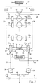
- FIG 2 illustrates a control system 7 of the present invention
- the axle 10 of a master roller 12 of the variator is mounted in the cavity 14 of the hollow shaft 16 of a double-acting piston 18.
- This piston is formed with opposed piston heads 20, 21 which slide under hydraulic load within coaxial cylindrical caps 23, 24 and which are free to rotate about the axis of shaft 16.
- a single-headed version of the same piston, with opposite faces of the single head both exposed to fluid, would also be possible.
- Hydraulic fluid inlets 26, 27 and outlets 29, 30 are formed in the end and side walls of caps 23. 24 respectively, and by means of a plurality of similar supply branches 25, 25a also feeding the end caps of the slave cylinders.
- the pressures in the corresponding slave cylinders of the remaining rollers (1-5) are related to those in caps 23, 24 so that the traction forces are equal.
- a hydraulic control circuit for such a transmission comprises two sources of hydraulic fluid provided by oil pumps 32, 33 capable of delivering hydraulic fluid from a sump 35 at. for example, between 30 to 50 bar to left-hand and right-hand upstream flow lines 37 and 38 and it is these lines that deliver the fluid respectively to the cylinder inlets 26 and 27.
- Such pumps will, however, not provide hydraulic fluid at these pressures unless control values (58, 59) or their respective hydraulic outlets (29, 30) are sufficiently restricted.
- a cross-connection 43 between lines 37 and 38 communicates by way of a 'higher-pressure-wins' arrangement of non-return valves 45 and 46 and via a conduit 48, with the main (high pressure) chamber of the end load mechanism of the transmission, that is to say the chamber 50 in Figures 3 and 4. This ensures that chamber 50 is always fed with fluid at a pressure equal to the higher of the two pressures in lines 37 and 38.
- Outlets 29 and 30 from caps 23 and 24 lead by way of downstream left-hand and right-hand lines 55 and 56 to the inlets of two electro-hydraulic proportional pressure control valves 58 and 59, the operation of which is described later herein.
- a cross-connection 61 between left-hand and right-hand lines 55 and 56 communicates by way of a 'lower-pressure-wins' arrangement of valves 63 and 64, and a connection 66 connects with a compensation chamber of the end load mechanism of the transmission, that is to say the chamber 89 in Figure 3 or 99 in Figure 4. Between them. valves 63, 64 ensure that the compensating pressure in the end load arrangement is always equal to the lower pressure in the roller control cylinders 23, 24. As an alternative, items 61-66 may be relocated adjacent items 43-46.
- connection 70 Downstream of the control valves 58 and 59, the left and right hand fluid lines combine at 68 after which a connection 70 is operable to provide fluid for general lubrication of the transmission. This is maintained at the correct back pressure by pressure relief valve 72.
- Reference numeral 74 indicates an alternative connection (at back pressure) for the end load compensating assembly (in place of connection 66).
- a suitable variator end load mechanism comprises a hollow casing member 76 secured to an input rotor 78 of the variator and main and auxiliary pistons 80, 81 housed within the casing member.
- Reference numeral 83 indicates an end stop for piston 80.
- the rotor 78, piston 80 and spacing assembly 91 are splined either directly or indirectly to the variator shaft 85 and annular seals indicated in the Figure hydraulically isolate from one another the main end load chamber 50 (between rotor 78 and pistons 80,81), the pre-load chamber 87 (between piston 80 and piston 81), and the so-called compensation chamber 89 (between the piston 80 and the end wall of the casing member 76). Spacing assembly 91 limits the distance of closest approach between the piston 81 and rotor 78.
- the mechanism is completed by a Belleville disc spring 93 acting between the outer face of auxiliary piston 81 and the adjacent stepped face of the main piston 80 and by passageways 95, 96, 97 connecting the chambers 89, 50 and 87 with hydraulic lines 66 and 48 and atmosphere respectively.
- passageway 95 could be arranged to connect chamber 89 with the system back pressure.
- the end load mechanism is full of oil and rotates at the variator input speed.
- the variator must resist finite inertia loads during the rapid accelerations experienced by the transmission at engine start. Since the hydraulic pumps are also engine driven and hydraulic end load is not available, an alternative end load device must be provided and this is supplied by the Belleville spring fitted between the two pistons 80, 81. It will therefore be understood that the arrangement applies mechanical end load during engine start, but that this pre-load can be cancelled hydraulically, to any degree, depending upon the physical dimensions of the assembly and the applied pressures.
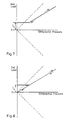
- the operation of the Belleville spring is best illustrated by reference to figures 7 and 8 from which it will be appreciated that the total end load pressure is a product of the Belleville spring load IL, the pressure (CP) in the high pressure chamber and the pressure (TP) in the compensating chamber.
- the initial spring load IL is only overcome once the differential pressure (CP-TP) is greater than IL and thenceafter, the end load pressure rises in a proportional relationship with the differential pressure, the specifics of which depend very much on the size relationships of the piston between the HP and CP chambers.
- Figure 8 illustrates that the effect of spring load IL can be cancelled hydraulically by raising both HP and CP in a controlled manner so as to eliminate the loading effect of the spring. This is aptly demonstrated by reference to the lower portion of figure 8 from which it will be appreciated that the effect of the spring can be cancelled such that the end load passes through zero as the load is removed.
- Other variations will however present themselves to a person skilled in the art.
- electro- hydraulic proportional pressure control valves 52, 59 are operated in a manner well known to create the desired back pressures in lines 55, 56 and end caps 23, 24 in order to effect movement of the master rollers 12 to a desired position. In effect, it is the difference between the higher line pressure (control pressure) and the lower line pressure (trailing pressure) that determines the torques in the transmission.
- the rollers are said to be under "differential control”.
- the end load arrangement also employs the difference between the higher and the lower of the two pressures in the hydraulic circuit and, hence, is also under "differential control".
- the basic hydraulics of the new system ensures that the tangential traction force (TF) is equal to half the net force applied by the control pressure (CP) acting on the double-acting roller-control pistons less the trailing pressure (TP) in the transverse plane of the variator.
- TF tangential traction force
- CP control pressure
- TP trailing pressure
- CA the castor angle
- the variator control system of the present invention compares very favourably with that of GB-A-1 600 974 because as a result of there being no effective trailing pressure in the roller-control pistons in this prior arrangement, any low pressure applied there for end load compensation will increase the operating traction coefficient with the attendant danger of exceeding the limiting value, and the undesirable consequences already outlined above.
- the compensation pressure is accessed from the lubrication point 70 in the Figure 1 circuit (back pressure) rather than from the line 66 (trailing pressure).
- back pressure although not requiring a 'lower-pressure-wins' valve assembly, does not fully compensate for the trailing pressure because of pressure drops (flow losses) in the circuit.
- the prime function of the present invention is to vary the end load in sympathy with changes in the net force exerted by the roller-control pistons so as to maintain the traction coefficient (CT) at the roller-disc interface consistently below a limit at which traction would be lost.
- CT traction coefficient
- the above apparatus provides one possible way of achieving this effect, it will be appreciated that any one of a number of different methods may be employed. For example, one might employ a valving arrangement 150 as shown in figure 6 which comprises first and second chambers 152, 154 respectively and a double headed piston arrangement shown generally at 156.
- the first piston 156a is contained within first chamber 152 and acts to divide it into two portions 152a, 152b fed with hydraulic fluid from the highest-pressure-wins and lowest-pressure-wins valving arrangements respectively.
- the second piston 156b is contained within the second chamber and is operably connected via joining member 158 to the first piston 156a for movement therewith.
- the second chamber On a side remote from joining member 158 the second chamber is provided with an inlet 159 for receiving hydraulic fluid from an independently operable pump 160 under the control of controller 162.
- a first outlet 164 from the second chamber supplies hydraulic fluid for end load purposes and may supply a simple single chamber end load arrangement such as that shown in figure 1. It will be appreciated that this outlet may be replaced with a simple outlet (not shown ) in inlet 159.
- a second outlet 166 is positioned below piston 156b and acts to return hydraulic fluid to sump 35 (fig 2).
- the positional relationship between piston 156b and outlet 166 is such that the piston acts to control the flow through outlet 166 and, hence, pressure P 1 and the magnitude of the endforce. Should P 1 rise above a pre-determined value, piston 156b moves to open the outlet and restore the correct pressure. Conversely, should it prove necessary, piston 156b can move to obturate the outlet 166 ( either partially or completely ) and restore pressure.
- a further outlet 167 is provided to drain the area behind piston 156b and allow for the escape of air trapped therebehind. If desirable, outlet 167 could be positioned such that it also provides a pressure release in the event of excessive pressure build up.
- controller 162 could employ controller 162 to vary the output of pump 160 and hence pressure P 1 such that it never exceeds a pre-determined value. Such a situation might, for example, arise at high rotational speeds where the centrifugal pressure effect experienced by the hydraulics in the end-load mechanism has a significant and adverse effect on the total end load.
- hydraulic pump 160 is operated and creates a pressure P1, in second chamber 154 which acts on second piston 156b and also supplies hydraulic pressure for end-load purposes.
- the pressure P2, P3 experienced on either side of the first piston 156a, are equal to the high and low pressure in lines 48 and 66 respectively.
- the difference between P2 and P3 is used against P1 such that piston 156b moves in the direction of one or other of the arrows W depending on the magnitude of the difference between P1 and P2-P3 so as to increase or decrease the resistance in outlet 166.
- valve 200 comprises first and second inlets 202, 204, for receiving fluid at first and second pressures P6, P7, outlet 206 for receiving fluid at the lower of the two pressures P6, P7 and an obturator means shown generally at 208 responsive to the different pressures to facilitate the passage of only the lowest pressure fluid to said outlet 206.
- the valve further includes two chambers 210, 212 each associated with a respective inlet and a duct 214 in fluid communication at a first end 214a with chamber 210 and at its otherwise free second end 214b with chamber 212.
- a mid point of the duct 214 is connected to the valve outlet 206 for the passage of fluid in a manner to be described later.
- Each end of the duct includes a sealing land 216, 218.
- Further features of the valve comprise a pair of sealing members shown in the form of. for example, balls 220, 222 (63, 64 in Fig 2) which are each free to move within the constraints of respective chambers 210, 212 and act to either cover or uncover respective ends of duct 214.
- the two sealing members 220, 222 are spaced apart by an amount greater than the distance between said sealing lands by a spacer member 224 extending therebetween such that, in operation, the fluid at the higher pressure causes movement of the sealing members to obturate the end associated with the higher pressure and maintain a given distance or gap G between the sealing member associated with the lower pressure fluid (220 in fig. 9).
- the opening into duct 214 remains uncovered and the lower pressure fluid is free to pass to outlet 26, thereby to provide fluid at the lower of the two pressures for subsequent use.
Landscapes
- Engineering & Computer Science (AREA)
- General Engineering & Computer Science (AREA)
- Mechanical Engineering (AREA)
- Theoretical Computer Science (AREA)
- Physics & Mathematics (AREA)
- Fluid Mechanics (AREA)
- Friction Gearing (AREA)
- Safety Valves (AREA)
- Control Of Transmission Device (AREA)
Description
Claims (13)
- A variator assembly comprising a variator of the toroidal-race rolling-traction type having input and output discs (78,79), hydraulic piston actuated rollers (12) positioned between said discs and operative to transmit traction there between and end loading means (89,50) to bias a disc towards the other, hydraulic control means (58,59) operative to vary the end load in sympathy with changes in the force exerted by the roller-control piston (20,21) so as to maintain the traction coefficient at the roller-disc interface consistently below the limit at which traction would be lost, characterised in that:the roller control pistons (20,21) comprise double-acting pistons controlled by the difference between the pressures in the hydraulic control means (58,59), and by a first valve (45,46) communicating with said first and second hydraulic circuits (37,38) of said hydraulic control means to supply fluid at a higher of two pressures in the circuits to a higher-pressure chamber (50) of the end loading means, anda second valve (63,64) communicating with said first and second hydraulic circuits (37,38) to supply fluid at a lower of two pressures in the circuits to a compensating chamber (89) of the end loading means.
- A variator assembly as claimed in Claim 1 in which the first valve (45, 46) comprises a higher-pressure win valve and said second valve (63, 64) comprises a lower-pressure win valve.
- A variator as claimed in Claim 1 or 2 in which said control means comprises means (58,59) for varying the end-load in accordance with a predefined function of the force exerted by the roller-control pistons (20,21).
- A variator as claimed in any one of Claims 1 to 3 in which said control means (58,59) comprises means for varying the end-load in proportion to the force exerted by the roller-control pistons (20,21).
- A variator as claimed in any one of claims 1 to 4 in which the end-loading means (50,89;50,99)comprises means for applying an end-load force proportional to the force exerted by the roller-control pistons (20,21).
- A variator as claimed in Claim 5 in which the double-acting roller-control pistons (20,21) comprise opposed piston heads sliding within separate co-axial cylindrical caps (23,24) each of which is fed by a separate source of hydraulic fluid.
- A variator as claimed in claim 5 in which the double-acting roller-control pistons (20,21) comprise single-headed pistons within a cylindrical chamber, opposite faces of each said piston being exposed to separate sources of hydraulic fluid the pressure of which is controllable independently of the other.
- A variator as claimed in any one of claims 5 to 7 in which the end-loading means (50,89;50,99) comprises a high pressure chamber (50) and a compensating pressure chamber (89;99) the latter of which is provided with hydraulic fluid at a pressure equal to the lower of the two pressures acting on the roller-control pistons (20,21).
- A variator as claimed in claim 8 in which the high pressure chamber (50) of the end load means is provided with hydraulic fluid at a pressure equal to the higher of the two pressures acting on the roller-control pistons (20,21).
- A variator as claimed in any one of claims 5 to 9 in which the control means (58,59) includes parallel first and second hydraulic circuits (37,55;38,56) each of which is supplied with its own hydraulic fluid from one or other of said source by means of its own pressuring pump (32,33) and each of which is provided with its own pressure control valve (58,59) for creating a desired pressure within that circuit.
- A variator as claimed in claim 10 including a lubrication circuit (74) having means (72) for controlling the pressure therein and in which said lubrication circuit is connected for supplying fluid at a controlled pressure to the compensating chamber (89;99) of the end-loading means.
- A lower-pressure-wins valve in a variator as claimed in any one of claims 1 to 11 comprising first and second inlets (202,204) for receiving fluid at first and second pressures, an outlet (206) for the fluid at the lower of the two pressures supplied to the valve and obturator means (220,222,224) responsive to said first and second pressures to facilitate the passage only of the lower pressure fluid to said outlet (206).
- A valve as claimed in claim 12 in which said obturator means (220,222,224) comprises a duct (214) in fluid communication at a first end with the source of high pressure fluid, at a second end with the source of low pressure fluid and at an intermediate point to said outlet (206) each end of said duct having a sealing land for co-operation with one or other of a pair of sealing members, said sealing members being spaced apart by an amount greater than the distance between said sealing lands (214a,214b) by a spacer member (224) extending therebetween, such that, in operation, the fluid at the higher pressure causes movement of the sealing members (220,222) to obturate the end associated with the high pressure fluid and unobturate the end associated with the low pressure fluid thereby to cause low pressure fluid to be passed to the outlet (206).
Priority Applications (1)
| Application Number | Priority Date | Filing Date | Title |
|---|---|---|---|
| EP99116024A EP0959269A3 (en) | 1996-04-19 | 1997-04-02 | Flow valve |
Applications Claiming Priority (3)
| Application Number | Priority Date | Filing Date | Title |
|---|---|---|---|
| GB9608146A GB2312257A (en) | 1996-04-19 | 1996-04-19 | Toroidal race variator control system varies end loading according to net pres sure |
| GB9608146 | 1996-04-19 | ||
| PCT/GB1997/000938 WO1997040292A1 (en) | 1996-04-19 | 1997-04-02 | Variator control system |
Related Child Applications (1)
| Application Number | Title | Priority Date | Filing Date |
|---|---|---|---|
| EP99116024A Division EP0959269A3 (en) | 1996-04-19 | 1997-04-02 | Flow valve |
Publications (2)
| Publication Number | Publication Date |
|---|---|
| EP0894210A1 EP0894210A1 (en) | 1999-02-03 |
| EP0894210B1 true EP0894210B1 (en) | 2000-05-24 |
Family
ID=10792358
Family Applications (2)
| Application Number | Title | Priority Date | Filing Date |
|---|---|---|---|
| EP99116024A Withdrawn EP0959269A3 (en) | 1996-04-19 | 1997-04-02 | Flow valve |
| EP97915588A Expired - Lifetime EP0894210B1 (en) | 1996-04-19 | 1997-04-02 | Variator control system |
Family Applications Before (1)
| Application Number | Title | Priority Date | Filing Date |
|---|---|---|---|
| EP99116024A Withdrawn EP0959269A3 (en) | 1996-04-19 | 1997-04-02 | Flow valve |
Country Status (12)
| Country | Link |
|---|---|
| EP (2) | EP0959269A3 (en) |
| JP (2) | JP2000508745A (en) |
| CN (2) | CN1109206C (en) |
| AU (1) | AU714997B2 (en) |
| BR (1) | BR9710656A (en) |
| CA (1) | CA2251817A1 (en) |
| DE (1) | DE69702132T2 (en) |
| ES (1) | ES2148955T3 (en) |
| GB (1) | GB2312257A (en) |
| RU (2) | RU2199685C2 (en) |
| WO (1) | WO1997040292A1 (en) |
| ZA (1) | ZA973195B (en) |
Cited By (1)
| Publication number | Priority date | Publication date | Assignee | Title |
|---|---|---|---|---|
| US8733191B2 (en) | 2005-06-14 | 2014-05-27 | Torotrak (Development) Limited | Power take off arrangement for a motor vehicle |
Families Citing this family (30)
| Publication number | Priority date | Publication date | Assignee | Title |
|---|---|---|---|---|
| GB2337090A (en) | 1998-05-08 | 1999-11-10 | Torotrak Dev Ltd | Hydraulic control circuit for a continuously-variable ratio transmission |
| DE19859380A1 (en) * | 1998-12-22 | 2000-07-13 | Volkswagen Ag | Gearbox with continuously variable transmission ratio and method for distributing torque to output shafts |
| JP4196486B2 (en) * | 1999-06-29 | 2008-12-17 | 日本精工株式会社 | Toroidal type continuously variable transmission |
| DE60204898T2 (en) * | 2001-08-31 | 2006-05-11 | Torotrak (Development) Ltd., Leyland | STAGE-FREE TRANSMISSION AND ITS CONTROL PROCEDURE |
| DE10233090A1 (en) * | 2002-07-19 | 2004-01-29 | Daimlerchrysler Ag | Gear change box for a vehicle comprises an infinitely variable toroidal drive arranged in the power flow between an input shaft and an output shaft and consisting of a driving toroidal disk, a driven toroidal disk, and a roller |
| WO2004061336A1 (en) * | 2003-01-06 | 2004-07-22 | Ulrich Rohs | Pressing device for tensioning two gearing elements, gearing provided with a pressing device of this type, and method for operating such a friction gearing |
| GB0316379D0 (en) * | 2003-07-12 | 2003-08-13 | Torotrak Dev Ltd | A continuously variable ratio transmission unit |
| GB0317499D0 (en) * | 2003-07-25 | 2003-08-27 | Torotrak Dev Ltd | Hydraulic variator control arrangement |
| JP4605495B2 (en) * | 2004-08-17 | 2011-01-05 | 日本精工株式会社 | Toroidal continuously variable transmission |
| JP4919687B2 (en) * | 2006-03-31 | 2012-04-18 | 株式会社エクォス・リサーチ | Toroidal continuously variable transmission |
| GB0611265D0 (en) * | 2006-06-08 | 2006-07-19 | Torotrak Dev Ltd | Arrangement for control of a continuously variable transmission |
| JP2008106787A (en) * | 2006-10-23 | 2008-05-08 | Jtekt Corp | Toroidal continuously variable transmission |
| JP4962328B2 (en) * | 2008-01-18 | 2012-06-27 | 日本精工株式会社 | Toroidal continuously variable transmission |
| GB0921118D0 (en) | 2009-12-02 | 2010-01-20 | Torotrak Dev Ltd | A control system for a vehicle drivetrain |
| US8578802B2 (en) | 2009-12-16 | 2013-11-12 | Allison Transmission, Inc. | System and method for multiplexing gear engagement control and providing fault protection in a toroidal traction drive automatic transmission |
| KR20120106976A (en) * | 2009-12-16 | 2012-09-27 | 알리손 트랜스미션, 인크. | System and method for controlling endload force of a variator |
| US8676515B2 (en) | 2009-12-16 | 2014-03-18 | Allison Transmission, Inc. | System and method for detecting clutch-related faults in an automatic transmission |
| US8852049B2 (en) | 2009-12-16 | 2014-10-07 | Allison Transmission, Inc. | Fast valve actuation system for an automatic transmission |
| WO2011075245A1 (en) | 2009-12-16 | 2011-06-23 | Allison Transmission, Inc. | Variator lockout valve system |
| GB2478003B (en) * | 2010-02-23 | 2012-07-25 | Torotrak Dev Ltd | Variator traction control arrangement |
| JP5822909B2 (en) * | 2010-03-29 | 2015-11-25 | シェフラー テクノロジーズ アー・ゲー ウント コー. カー・ゲーSchaeffler Technologies AG & Co. KG | Hydraulic system for continuously variable transmission |
| CN103370256B (en) | 2010-12-15 | 2016-08-10 | 艾里逊变速箱公司 | Double pump for vehicle transmission regulates system |
| CN103370562B (en) | 2010-12-15 | 2016-03-23 | 艾里逊变速箱公司 | For controlling to equipment and the method for the fluid stream of gear in automatic transmission |
| WO2012082845A2 (en) | 2010-12-15 | 2012-06-21 | Long Charles F | Variator switching valve scheme for a torroidal traction drive transmission |
| WO2013163309A1 (en) | 2012-04-25 | 2013-10-31 | Brian Schoolcraft | Nested endload assembly for a variator |
| US9400051B2 (en) | 2012-06-15 | 2016-07-26 | Allison Transmisson, Inc. | Cold operation mode control for an IVT |
| JP6157618B2 (en) * | 2013-06-21 | 2017-07-05 | 本田技研工業株式会社 | Toroidal continuously variable transmission |
| CN105465355B (en) * | 2014-09-03 | 2018-03-06 | 上海汽车集团股份有限公司 | Double-clutch speed changer and its hydraulic control system |
| US9702459B2 (en) * | 2015-02-11 | 2017-07-11 | Orbital Traction, Ltd. | Preload and torsional backlash management for a continuously variable transmission device |
| WO2018071376A1 (en) * | 2016-10-11 | 2018-04-19 | Dana Limited | Hydraulic and centrifugal clamping for high-speed continuously variable planetary operation |
Family Cites Families (14)
| Publication number | Priority date | Publication date | Assignee | Title |
|---|---|---|---|---|
| GB979062A (en) * | 1960-05-18 | 1965-01-01 | Nat Res Dev | Improvements in or relating to a continuously variable ratio transmission |
| GB1078791A (en) * | 1964-12-01 | 1967-08-09 | Nat Res Dev | Continuously variable ratio transmission system and control system therefor |
| CH540440A (en) * | 1969-06-23 | 1973-08-15 | Rilco Maschf | Static, fluid-operated switching element |
| GB1325602A (en) * | 1970-06-06 | 1973-08-08 | Rotax Ltd | Transmission systems |
| US3828618A (en) * | 1971-07-27 | 1974-08-13 | Rotax Ltd | Constant speed hydraulically controlled toric transmission with concentric, two piston valve, governor and constant ratio means |
| US3925987A (en) * | 1972-10-06 | 1975-12-16 | Jacques Faisandier | Hydraulic control circuit |
| GB1600974A (en) | 1977-08-05 | 1981-10-21 | Lucas Industries Ltd | Variable speed transmission systems |
| GB2023735B (en) * | 1978-04-05 | 1982-06-09 | Ace Vulcanising Ltd | Pressure-applying unit |
| GB2023753B (en) * | 1978-06-23 | 1982-12-22 | Brie Perry F G De | Control systems for steplessly-varibale ratio transmissions |
| GB2100372B (en) * | 1979-06-20 | 1983-06-02 | Nat Res Dev | Improvements in or relating to steplesslyvariable ratio transmissions |
| GB2108600A (en) * | 1981-10-24 | 1983-05-18 | Leyland Vehicles | Continuously-variable-ratio transmisson |
| US4854920A (en) * | 1986-08-26 | 1989-08-08 | Mitsubishi Denki Kabushiki Kaisha | Control device of non-stage transmission |
| GB8819430D0 (en) * | 1988-08-16 | 1988-09-21 | Greenwood C J | Improvements in/relating to hydraulic control circuits for continuously-variable-ratio transmissions |
| GB9214190D0 (en) * | 1992-07-03 | 1992-08-12 | Robinson Leslie K | Improvements in or relating to continuously-variable-ratio transmissions of the toroidal-race rolling-traction type |
-
1996
- 1996-04-19 GB GB9608146A patent/GB2312257A/en not_active Withdrawn
-
1997
- 1997-04-02 RU RU98120910/28A patent/RU2199685C2/en not_active IP Right Cessation
- 1997-04-02 WO PCT/GB1997/000938 patent/WO1997040292A1/en active IP Right Grant
- 1997-04-02 EP EP99116024A patent/EP0959269A3/en not_active Withdrawn
- 1997-04-02 EP EP97915588A patent/EP0894210B1/en not_active Expired - Lifetime
- 1997-04-02 JP JP9537806A patent/JP2000508745A/en not_active Ceased
- 1997-04-02 CN CN97195383A patent/CN1109206C/en not_active Expired - Fee Related
- 1997-04-02 AU AU23013/97A patent/AU714997B2/en not_active Ceased
- 1997-04-02 DE DE69702132T patent/DE69702132T2/en not_active Expired - Lifetime
- 1997-04-02 BR BR9710656A patent/BR9710656A/en not_active IP Right Cessation
- 1997-04-02 ES ES97915588T patent/ES2148955T3/en not_active Expired - Lifetime
- 1997-04-02 CA CA002251817A patent/CA2251817A1/en not_active Abandoned
- 1997-04-15 ZA ZA973195A patent/ZA973195B/en unknown
-
2001
- 2001-12-28 JP JP2001399911A patent/JP2002227953A/en active Pending
-
2002
- 2002-01-02 CN CN02101510A patent/CN1368610A/en active Pending
- 2002-01-22 RU RU2002102056/28A patent/RU2002102056A/en not_active Application Discontinuation
Cited By (1)
| Publication number | Priority date | Publication date | Assignee | Title |
|---|---|---|---|---|
| US8733191B2 (en) | 2005-06-14 | 2014-05-27 | Torotrak (Development) Limited | Power take off arrangement for a motor vehicle |
Also Published As
| Publication number | Publication date |
|---|---|
| RU2002102056A (en) | 2003-09-27 |
| AU714997B2 (en) | 2000-01-13 |
| JP2002227953A (en) | 2002-08-14 |
| EP0959269A3 (en) | 2000-10-04 |
| JP2000508745A (en) | 2000-07-11 |
| AU2301397A (en) | 1997-11-12 |
| ZA973195B (en) | 1998-10-15 |
| CN1109206C (en) | 2003-05-21 |
| CA2251817A1 (en) | 1997-10-30 |
| DE69702132D1 (en) | 2000-06-29 |
| CN1368610A (en) | 2002-09-11 |
| GB2312257A (en) | 1997-10-22 |
| ES2148955T3 (en) | 2000-10-16 |
| EP0959269A2 (en) | 1999-11-24 |
| BR9710656A (en) | 1999-08-17 |
| RU2199685C2 (en) | 2003-02-27 |
| GB9608146D0 (en) | 1996-06-26 |
| EP0894210A1 (en) | 1999-02-03 |
| WO1997040292A1 (en) | 1997-10-30 |
| CN1221479A (en) | 1999-06-30 |
| DE69702132T2 (en) | 2000-11-09 |
Similar Documents
| Publication | Publication Date | Title |
|---|---|---|
| EP0894210B1 (en) | Variator control system | |
| US6030310A (en) | Variator control system | |
| US5090951A (en) | Hydraulic control circuits for continuously-variable-ratio transmissions | |
| US6162144A (en) | Traction coefficient control for a continuously variable transmission | |
| KR101440848B1 (en) | Continuously variable transmission | |
| JP5179280B2 (en) | Apparatus for transmitting torque from vehicle drive train to vehicle wheels and method for transmitting torque to vehicle drive components | |
| EP1421300B1 (en) | Continuously variable transmission and method of operation thereof | |
| US3354978A (en) | Speed responsive hydrostatic device | |
| JP2009079757A (en) | Hydraulic vehicle clutch mechanism and method | |
| US4524641A (en) | Continuously-variable ratio-transmission | |
| JPH04228960A (en) | Continuous variable transmission | |
| US5308297A (en) | Transmissions of the toroidal-race rolling-traction type | |
| CA1080127A (en) | Torque equalizer for a hydraulically driven four-wheel-drive vehicle | |
| US3451283A (en) | Infinitely variable cone pulley transmission | |
| US20070072736A1 (en) | Continuously variable ratio transmission unit | |
| EP1649199B1 (en) | Hydraulic variator control arrangement | |
| KR100496789B1 (en) | A lower-pressure-wins valve and a variator assembly comprising the same | |
| EP0281369B1 (en) | Vane type variable displacement motor | |
| JPH01116367A (en) | Toroidal type continuously variable transmission |
Legal Events
| Date | Code | Title | Description |
|---|---|---|---|
| PUAI | Public reference made under article 153(3) epc to a published international application that has entered the european phase |
Free format text: ORIGINAL CODE: 0009012 |
|
| 17P | Request for examination filed |
Effective date: 19981022 |
|
| AK | Designated contracting states |
Kind code of ref document: A1 Designated state(s): DE ES FR GB IT |
|
| 17Q | First examination report despatched |
Effective date: 19990215 |
|
| GRAG | Despatch of communication of intention to grant |
Free format text: ORIGINAL CODE: EPIDOS AGRA |
|
| GRAG | Despatch of communication of intention to grant |
Free format text: ORIGINAL CODE: EPIDOS AGRA |
|
| GRAG | Despatch of communication of intention to grant |
Free format text: ORIGINAL CODE: EPIDOS AGRA |
|
| GRAH | Despatch of communication of intention to grant a patent |
Free format text: ORIGINAL CODE: EPIDOS IGRA |
|
| GRAH | Despatch of communication of intention to grant a patent |
Free format text: ORIGINAL CODE: EPIDOS IGRA |
|
| GRAA | (expected) grant |
Free format text: ORIGINAL CODE: 0009210 |
|
| AK | Designated contracting states |
Kind code of ref document: B1 Designated state(s): DE ES FR GB IT |
|
| ITF | It: translation for a ep patent filed |
Owner name: JACOBACCI & PERANI S.P.A. |
|
| REF | Corresponds to: |
Ref document number: 69702132 Country of ref document: DE Date of ref document: 20000629 |
|
| ET | Fr: translation filed | ||
| REG | Reference to a national code |
Ref country code: ES Ref legal event code: FG2A Ref document number: 2148955 Country of ref document: ES Kind code of ref document: T3 |
|
| PLBE | No opposition filed within time limit |
Free format text: ORIGINAL CODE: 0009261 |
|
| STAA | Information on the status of an ep patent application or granted ep patent |
Free format text: STATUS: NO OPPOSITION FILED WITHIN TIME LIMIT |
|
| 26N | No opposition filed | ||
| REG | Reference to a national code |
Ref country code: GB Ref legal event code: IF02 |
|
| PGFP | Annual fee paid to national office [announced via postgrant information from national office to epo] |
Ref country code: FR Payment date: 20060425 Year of fee payment: 10 |
|
| PGFP | Annual fee paid to national office [announced via postgrant information from national office to epo] |
Ref country code: ES Payment date: 20060526 Year of fee payment: 10 |
|
| REG | Reference to a national code |
Ref country code: ES Ref legal event code: FD2A Effective date: 20070403 |
|
| PG25 | Lapsed in a contracting state [announced via postgrant information from national office to epo] |
Ref country code: FR Free format text: LAPSE BECAUSE OF NON-PAYMENT OF DUE FEES Effective date: 20070430 |
|
| PG25 | Lapsed in a contracting state [announced via postgrant information from national office to epo] |
Ref country code: ES Free format text: LAPSE BECAUSE OF NON-PAYMENT OF DUE FEES Effective date: 20070403 |
|
| PGFP | Annual fee paid to national office [announced via postgrant information from national office to epo] |
Ref country code: IT Payment date: 20100416 Year of fee payment: 14 |
|
| PG25 | Lapsed in a contracting state [announced via postgrant information from national office to epo] |
Ref country code: IT Free format text: LAPSE BECAUSE OF NON-PAYMENT OF DUE FEES Effective date: 20110402 |
|
| PGFP | Annual fee paid to national office [announced via postgrant information from national office to epo] |
Ref country code: DE Payment date: 20130419 Year of fee payment: 17 |
|
| PGFP | Annual fee paid to national office [announced via postgrant information from national office to epo] |
Ref country code: GB Payment date: 20140422 Year of fee payment: 18 |
|
| REG | Reference to a national code |
Ref country code: DE Ref legal event code: R119 Ref document number: 69702132 Country of ref document: DE |
|
| REG | Reference to a national code |
Ref country code: DE Ref legal event code: R119 Ref document number: 69702132 Country of ref document: DE Effective date: 20141101 |
|
| PG25 | Lapsed in a contracting state [announced via postgrant information from national office to epo] |
Ref country code: DE Free format text: LAPSE BECAUSE OF NON-PAYMENT OF DUE FEES Effective date: 20141101 |
|
| GBPC | Gb: european patent ceased through non-payment of renewal fee |
Effective date: 20150402 |
|
| PG25 | Lapsed in a contracting state [announced via postgrant information from national office to epo] |
Ref country code: GB Free format text: LAPSE BECAUSE OF NON-PAYMENT OF DUE FEES Effective date: 20150402 |