EP0893590B1 - Air intake control system for engine equipped with exhaust gas recirculation feature - Google Patents
Air intake control system for engine equipped with exhaust gas recirculation feature Download PDFInfo
- Publication number
- EP0893590B1 EP0893590B1 EP98113609A EP98113609A EP0893590B1 EP 0893590 B1 EP0893590 B1 EP 0893590B1 EP 98113609 A EP98113609 A EP 98113609A EP 98113609 A EP98113609 A EP 98113609A EP 0893590 B1 EP0893590 B1 EP 0893590B1
- Authority
- EP
- European Patent Office
- Prior art keywords
- target
- air
- valve opening
- engine
- throttle valve
- Prior art date
- Legal status (The legal status is an assumption and is not a legal conclusion. Google has not performed a legal analysis and makes no representation as to the accuracy of the status listed.)
- Expired - Lifetime
Links
Images


Classifications
-
- F—MECHANICAL ENGINEERING; LIGHTING; HEATING; WEAPONS; BLASTING
- F02—COMBUSTION ENGINES; HOT-GAS OR COMBUSTION-PRODUCT ENGINE PLANTS
- F02D—CONTROLLING COMBUSTION ENGINES
- F02D41/00—Electrical control of supply of combustible mixture or its constituents
- F02D41/0025—Controlling engines characterised by use of non-liquid fuels, pluralities of fuels, or non-fuel substances added to the combustible mixtures
- F02D41/0047—Controlling exhaust gas recirculation [EGR]
- F02D41/005—Controlling exhaust gas recirculation [EGR] according to engine operating conditions
- F02D41/0057—Specific combustion modes
-
- F—MECHANICAL ENGINEERING; LIGHTING; HEATING; WEAPONS; BLASTING
- F02—COMBUSTION ENGINES; HOT-GAS OR COMBUSTION-PRODUCT ENGINE PLANTS
- F02D—CONTROLLING COMBUSTION ENGINES
- F02D33/00—Controlling delivery of fuel or combustion-air, not otherwise provided for
-
- F—MECHANICAL ENGINEERING; LIGHTING; HEATING; WEAPONS; BLASTING
- F02—COMBUSTION ENGINES; HOT-GAS OR COMBUSTION-PRODUCT ENGINE PLANTS
- F02D—CONTROLLING COMBUSTION ENGINES
- F02D41/00—Electrical control of supply of combustible mixture or its constituents
- F02D41/0025—Controlling engines characterised by use of non-liquid fuels, pluralities of fuels, or non-fuel substances added to the combustible mixtures
- F02D41/0047—Controlling exhaust gas recirculation [EGR]
- F02D41/005—Controlling exhaust gas recirculation [EGR] according to engine operating conditions
- F02D41/0052—Feedback control of engine parameters, e.g. for control of air/fuel ratio or intake air amount
-
- F—MECHANICAL ENGINEERING; LIGHTING; HEATING; WEAPONS; BLASTING
- F02—COMBUSTION ENGINES; HOT-GAS OR COMBUSTION-PRODUCT ENGINE PLANTS
- F02D—CONTROLLING COMBUSTION ENGINES
- F02D41/00—Electrical control of supply of combustible mixture or its constituents
- F02D41/30—Controlling fuel injection
- F02D41/3011—Controlling fuel injection according to or using specific or several modes of combustion
- F02D41/3017—Controlling fuel injection according to or using specific or several modes of combustion characterised by the mode(s) being used
- F02D41/3023—Controlling fuel injection according to or using specific or several modes of combustion characterised by the mode(s) being used a mode being the stratified charge spark-ignited mode
- F02D41/3029—Controlling fuel injection according to or using specific or several modes of combustion characterised by the mode(s) being used a mode being the stratified charge spark-ignited mode further comprising a homogeneous charge spark-ignited mode
-
- F—MECHANICAL ENGINEERING; LIGHTING; HEATING; WEAPONS; BLASTING
- F02—COMBUSTION ENGINES; HOT-GAS OR COMBUSTION-PRODUCT ENGINE PLANTS
- F02B—INTERNAL-COMBUSTION PISTON ENGINES; COMBUSTION ENGINES IN GENERAL
- F02B3/00—Engines characterised by air compression and subsequent fuel addition
- F02B3/06—Engines characterised by air compression and subsequent fuel addition with compression ignition
-
- F—MECHANICAL ENGINEERING; LIGHTING; HEATING; WEAPONS; BLASTING
- F02—COMBUSTION ENGINES; HOT-GAS OR COMBUSTION-PRODUCT ENGINE PLANTS
- F02D—CONTROLLING COMBUSTION ENGINES
- F02D41/00—Electrical control of supply of combustible mixture or its constituents
- F02D41/0002—Controlling intake air
- F02D2041/0017—Controlling intake air by simultaneous control of throttle and exhaust gas recirculation
-
- F—MECHANICAL ENGINEERING; LIGHTING; HEATING; WEAPONS; BLASTING
- F02—COMBUSTION ENGINES; HOT-GAS OR COMBUSTION-PRODUCT ENGINE PLANTS
- F02D—CONTROLLING COMBUSTION ENGINES
- F02D41/00—Electrical control of supply of combustible mixture or its constituents
- F02D41/30—Controlling fuel injection
- F02D41/38—Controlling fuel injection of the high pressure type
- F02D2041/389—Controlling fuel injection of the high pressure type for injecting directly into the cylinder
-
- F—MECHANICAL ENGINEERING; LIGHTING; HEATING; WEAPONS; BLASTING
- F02—COMBUSTION ENGINES; HOT-GAS OR COMBUSTION-PRODUCT ENGINE PLANTS
- F02D—CONTROLLING COMBUSTION ENGINES
- F02D2200/00—Input parameters for engine control
- F02D2200/02—Input parameters for engine control the parameters being related to the engine
- F02D2200/04—Engine intake system parameters
- F02D2200/0402—Engine intake system parameters the parameter being determined by using a model of the engine intake or its components
-
- F—MECHANICAL ENGINEERING; LIGHTING; HEATING; WEAPONS; BLASTING
- F02—COMBUSTION ENGINES; HOT-GAS OR COMBUSTION-PRODUCT ENGINE PLANTS
- F02D—CONTROLLING COMBUSTION ENGINES
- F02D2200/00—Input parameters for engine control
- F02D2200/02—Input parameters for engine control the parameters being related to the engine
- F02D2200/04—Engine intake system parameters
- F02D2200/0414—Air temperature
-
- F—MECHANICAL ENGINEERING; LIGHTING; HEATING; WEAPONS; BLASTING
- F02—COMBUSTION ENGINES; HOT-GAS OR COMBUSTION-PRODUCT ENGINE PLANTS
- F02D—CONTROLLING COMBUSTION ENGINES
- F02D2200/00—Input parameters for engine control
- F02D2200/70—Input parameters for engine control said parameters being related to the vehicle exterior
- F02D2200/703—Atmospheric pressure
-
- Y—GENERAL TAGGING OF NEW TECHNOLOGICAL DEVELOPMENTS; GENERAL TAGGING OF CROSS-SECTIONAL TECHNOLOGIES SPANNING OVER SEVERAL SECTIONS OF THE IPC; TECHNICAL SUBJECTS COVERED BY FORMER USPC CROSS-REFERENCE ART COLLECTIONS [XRACs] AND DIGESTS
- Y02—TECHNOLOGIES OR APPLICATIONS FOR MITIGATION OR ADAPTATION AGAINST CLIMATE CHANGE
- Y02T—CLIMATE CHANGE MITIGATION TECHNOLOGIES RELATED TO TRANSPORTATION
- Y02T10/00—Road transport of goods or passengers
- Y02T10/10—Internal combustion engine [ICE] based vehicles
- Y02T10/40—Engine management systems
Definitions
- the invention relates to an air intake control system for an engine equipped with an exhaust gas recirculation system which controls the amount of exhaust gas that is recirculated on the basis of a comparison of an air charging ratio with a target charging ratio.
- an exhaust gas recirculation system which has exhaust gas recirculation adjusting means and control means for determining a target amount of fresh air charge according to an operated position of an accelerator and an air charging ratio dictated by pressure in an intake air passage and a temperature of intake air and controlling the exhaust gas recirculation adjusting means to remove a difference between a practical amount of fresh air charge detected by an air flow sensor and a target amount of fresh air charge.
- a control system is known from, for example, Japanese Patent Publication No.63 - 5O544. This control system can be applied to gasoline engines as well as to diesel engines.
- control system includes an exhaust gas recirculation valve for regulating the amount of exhaust gas admitted to the engine and a throttle valve in an intake passage for controlling the amount of air charge towards a target amount and controls them to decrease detrimental compositions of exhaust gas by applying an appropriate amount of oxygen for fuel burning.
- a target throttle opening is determined on the basis of an amount of fuel injection and an outside air temperature
- a target EGR valve opening is determined on the basis of a recirculated exhaust gas temperature and a temperature of engine cooling water.
- the prior art control system is accompanied by aggravation of controllability of the amount of exhaust gas admitted to the engine in the event of, for example, an occurrence of a change in intake air density due to changes in atmospheric pressure and/or temperature.
- a reduction in intake air density caused due to a change in atmospheric pressure and temperature is accompanied by a reduction in mass of intake air if an engine operating condition and/or recirculation of exhaust gas remain unchanged.
- the exhaust gas recirculation adjusting means can be controlled to make up a downward tendency of intake air due to a decline in intake air density, which is however accompanied by a reduction in exhaust gas that is recirculated.
- a rise in intake air density is accompanied by an increase in exhaust gas that is recirculated.
- an intake air control system for an engine equipped with an exhaust gas recirculation system that comprises engine operating condition detecting means for detecting engine operating conditions including at least an engine speed, an throttle valve opening, an intake air temperature, an amount of intake air, an accelerator opening and atmospheric pressure, target throttle valve opening determining means for determining a target throttle valve opening of a throttle valve according to the detected engine operating condition, target EGR valve opening determining means for determining a target EGR valve opening according to the detected engine operating condition, and control means for controlling variable air intake means including a throttle valve towards die target valve opening.
- the target throttle valve opening determining means calculates a target engine output torque from the detected engine speed and the detected accelerator opening, determines a basic throttle valve opening according to the detected engine speed and the target engine output torque from a map that defines basic throttle valve openings with respect to engine speeds and target engine output torque, determines an estimated amount of air charge for calculation of a target throttle valve opening from volumetric efficiency that is determined according to the detected engine speed and the detected throttle valve opening from a map in which volumetric efficiency are defined with respect to engine speeds and throttle valve openings and then corrected according to the detected intake air temperature and said detected atmospheric pressure, determines the target amount of air charge according to the detected engine speed and the target engine output torque from a map in which target amounts of air charge are defined with respect to engine speeds and target engine output torque, and calculating the target throttle valve opening from a feedback correction value that is determined according to the target amount of air charge and the basic throttle valve opening and a difference between the estimated amount of air charge.
- the correction of volumetric efficiency has the tendency to decrease the estimated amount of air charge relative to the target amount of air charge for calculation of a target throttle valve opening as the intake air temperature drops.
- the target EGR valve opening determining means determines a basic EGR valve opening according to the detected engine speed and the target engine output torque from a map in which basic EGR valve openings are defined with respect to engine speeds and target engine output torque, determines a target amount of air charge for calculation of an EGR valve opening according to the detected engine speed and the target engine output torque from a map in which target amounts of air charge are defined with respect to engine speeds and target engine output torque, and calculates the target EGR valve opening from the basic EGR valve opening and a feedback correction value that is determined according to a difference between the target amount of air charge and an amount of air charge calculated from the detected amount of intake air.
- the air intake control system it is realized to control a change in EGR valve opening due to a drop in intake air density following an increase in intake air temperature by correcting a target throttle valve opening for prevention of expansion of a difference between an estimated amount of air charge for calculation of a target throttle valve opening and a target amount of air charge for calculation of a target throttle valve opening that is caused following a temperature rise of engine cooling water.
- the control of exhaust gas recirculation is performed with high accuracy.
- a marked effect of controlling a change in EGR valve opening takes place especially in a stratified charge combustion mode in which a large amount of exhaust gas is recirculated.
- variable air intake means is controlled to appropriately regulate the practical amount of intake air without an effect of affecting the control of exhaust gas recirculation through the exhaust gas regulating means, as a result of which, an appropriate amount of exhaust gas is admitted to the engine.
- the control of a practical amount of air charge by the variable air intake means may be performed while the exhaust gas recirculation system controls the exhaust gas regulating means.
- the air intake control system determines a basic throttle valve opening for the electrically actuated throttle valve according to engine operating conditions and corrects a practical throttle valve opening on the basis of the basic throttle valve opening and a difference between the estimated amount of air charge and the target amount of air charge. In this way, in the event of an occurrence of a downward or upward tendency of intake air due to a decline in intake air density, an opening of the throttle valve is corrected to adjust a practical amount of air charge.
- the amount of air charge may be estimated on the basis of an engine speed and a throttle valve opening correctively tempered with intake air density according to a temperature of intake air and the atmospheric pressure, which is always desirable for the variable air intake means, i e. the electrically actuated throttle valve, to perform more precise regulation of a practical amount of air charge in spite of a change in intake air density.
- the basic throttle valve opening and an controlled amount of the exhaust gas regulating means may be determined so that pressure in the intake air passage downstream from the electrically actuated throttle valve is made approximately equal to the atmospheric pressure in an extent of basic throttle openings less than its full position in an engine operating zone in which the control of exhaust gas regulating means and the control of the variable air intake means are performed.
- the basic throttle valve opening is always less than the full position even when the practical amount of air charge is increased, the throttle valve is appropriately controlled to increasingly change its opening according to a decline in intake air density if intake air density declines.
- the engine may be of a fuel direct injection type having a fuel injector which is controlled to inject fuel in a compression stroke to cause stratified charge combustion in a specified engine operating zone.
- a fuel direct injection type having a fuel injector which is controlled to inject fuel in a compression stroke to cause stratified charge combustion in a specified engine operating zone.
- an airfuel mixture is made lean and exhaust gas is recirculated with an effect of lowering NOx emissions and improving fuel efficiency.
- the engine 1O is comprised of a cylinder block la provided with cylinder bores 12 in which pistons 14 slide and a cylinder head lb.
- a combustion chamber 15 is formed in each eylinder by the top of the piston 14, a lower wall of the cylinder head lb and the cylinder bore 12.
- An intake port and an exhaust port open into the combustion chamber 15 and are opened and shut at a predetermined timing by an intake valve 17 and an exhaust valve 18, respectively.
- a spark plug 2O is installed in the eylinder head lb to with its electrode tip placed down into the combustion chamber 15.
- a fuel injector 22 projects into the combustion chamber 15 from the side and splays fuel directly into the combustion chamber 15.
- Air is introduced into the engine 1 through an intake line 24 including an intake passage 24a which is provided with an air cleaner 25, an air flow sensor 26, throttle valve 28 driven by an electric motor 27 and a surge tank 3O arranged in order from the upstream end.
- Exhaust gas is discharged into an exhaust line 32 including an exhaust passage 32a from the engine 1.
- the exhaust line 32 has a catalytic converter 33 disposed in the exhaust passage 32a.
- An exhaust gas recirculation system 35 is installed between the intake line 24 and the exhaust line 32 to admit an controlled amount of exhaust gas into the intake air stream.
- the exhaust gas recirculation system 35 incorporates an exhaust gas recirculation valve, such as a vacuum modulated exhaust gas recirculation valve (which is hereafter referred to as an EGR valve) 36, disposed in an exhaust gas recirculation passage 35a connected between the intake passage 24a and the exhaust passage 32a.
- the EGR valve 36 is actuated by a vacuum actuator 37 cooperating with a vacuum regulator 38 which is comprised of, for example, a pair of duty solenoid valves such as a vacuum induction duty solenoid valve and an atmosphere induction solenoid valve that regulate proportions of a vacuum and the atmosphere, respectively.
- the engine 1 is further provided with various sensors, namely a throttle sensor 41 for detecting a point of throttle opening, a speed sensor 42 for detecting an engine speed, an accelerator position sensor 43 for detecting a position of an accelerator (not shown), temperature sensors 44 and 46 for detecting temperatures of intake air and engine cooling water, respectively, a pressure sensor 45 for detecting the atmospheric pressure, an oxygen (02) sensor 47 for detecting the oxygen concentration of exhaust gas by which an air-fuel ratio is dictated, and a valve position sensor 48 for detecting a point of EGR valve opening.
- output signals from these sensors 42 - 48 are directed to an engine control unit (ECU) 5O comprised of, for example, a programmed microprocessor and stores various control maps.
- ECU engine control unit
- the engine control unit 5O controls the fuel injector 22, the throttle valve 28 and the EGR valve 36. Specifically, the engine control unit 5O provides control signals, such as a fuel injection control signal with which the fuel injector 22 is actuated to inject a controlled amount of fuel at a controlled timing, a throttle control signal with which the electric motor 27 actuates the throttle valve 28 to open to a controlled point of valve opening and a recirculation control signal with which the vacuum regulator 38 is caused to operate the vacuum actuator 37 so as thereby to control the EGR valve 36 to admit a controlled amount of exhaust gas that is recirculated.
- control signals such as a fuel injection control signal with which the fuel injector 22 is actuated to inject a controlled amount of fuel at a controlled timing, a throttle control signal with which the electric motor 27 actuates the throttle valve 28 to open to a controlled point of valve opening and a recirculation control signal with which the vacuum regulator 38 is caused to operate the vacuum actuator 37 so as thereby to control the EGR valve 36 to admit a controlled amount of
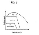
- FIG. 2 illustrates engine operating zones for various combustion modes and air-fuel ratios for the direct fuel injection engine.
- there are three engine operating zones namely a stratified charge combustion zone Z1 for lower engine speeds and loading and a homogeneous charge combustion zone for higher engine speeds and loading which is subdivided into two zones, namely a lean homogeneous charge combustion zone Z1 for moderate engine speeds and loading and a stoichiometric homogeneous charge combustion zone Z2 for higher engine speeds and loading.
- a stratified charge combustion zone Z1 fuel is sprayed in a later stage of a compression stroke with an effect of uneven distribution of a stratified air-fuel mixture around the spark plug 2O, as a result of which stratified charge combustion is made.
- the throttle valve 28 provides a large throttle opening to admit a large amount of intake air to the engine 1 to make an overall air-fuel mixture significantly lean at, for example, an air-fuel ratio of approximately 4O.
- fuel is sprayed in an early stage of a suction stroke with an effect of homogeneous distribution of an air-fuel mixture in the whole combustion chamber 15.
- FIG. 3 is a functional block diagram showing the engine control system 5O.
- the engine control system 50 determines target engine output torque Trqob based on an accelerator position Acc detected by the accelerator position sensor 43 and an engine speed Ne detected by the speed sensor 42 and an amount of intake air introduced into the engine 1 at function block 52. The determination is made by use of a target torque control map which specifies target engine torque relative to engine speeds and throttle openings. Further, the engine control system 5O determines an amount of air charge Ce based on an amount of intake air Afs introduced into the engine 1 which is dictated by an output signal from the air flow sensor 26 at function block 51.
- the engine control system 5O is subdivided into three sections, namely an air charging control section 53, a fuel injection control section 6O and an exhaust gas recirculation control section 65.
- the air charging control section 53 is comprised of blocks 54 - 57 for determining a basic throttle valve opening Tvob , an amount of air charge Ceco which is used for a correction of throttle opening, a target amount of air charge Ceob and a practical throttle valve opening Tvo , and a block 58 for providing a throttle valve control signal STvo .
- a basic throttle valve opening Tvob is determined according to an engine operating condition.
- the basic throttle valve opening Tvob In the stratified charge combustion zone Z1, while the basic throttle valve opening Tvob is determined to be large sufficiently to make an air-fuel mixture significantly lean, it is fixed at a position, which is less than its full position and in which the pressure of air stream in the intake passage 24a near the engine 1 is approximately equal to or desirably slightly higher than the atmospheric pressure, in spite of changes in engine loading during execution of the exhaust gas recirculation control.
- the basic throttle valve opening Tvob may be increased correspondingly to an increase in the amount of exhaust gas recirculation in an engine operating zone in which the basic EGR valve opening (which will be described later) Pegrb .
- the air charging control section 53 determines an amount of air charge Ceest estimated under the condition that it is granted that no exhaust gas is admitted to the engine 1.
- the estimation of the amount of air charge Ceest is made by tempering volumetric efficiency dictated by a current engine speed Ne and a current throttle valve opening Tvo with a corrected intake air density depending upon a temperature of intake air Tha and the atmospheric pressure Atp . Volumetric efficiency are specified in a map relative to engine speed Ne and throttle valve opening Tvo .
- the air charging control section 53 finds a target amount of air charge Ceob for conditions in which no exhaust gas is admitted to the engine 1. Target amounts of air charge Ceob are specified relative to engine speeds Ne and target engine output torque Trqob in a map.
- the map specifies amounts of air charge relative to engine speeds and engine output torque which are measured varying throttle valve opening in certain circumstances under interruption of exhaust gas recirculation by a bench test. Further, the air charging control section S3 determines a target throttle valve opening Tvoob based on the basic throttle valve opening Tvob and a beedback correction amount of air charge Ctfb meeting a difference between the target amount of air charge Ceob and the estimated amount of air charge Ceest at block S7, and provides for a control signal for driving the electric motor 27 to open the throttle valve 28 to the target throttle valve opening Tvoob at block 58.
- the fuel injection control section 6O determines a target air-fuel ratio meeting current engine operating conditions at block 61.
- a map for the stratified charge combustion zone Z1 specifies target air-fuel ratios A / Fob relative to engine speeds Ne and target engine output torque Trqob
- a map for the lean homogeneous charge combustion zone Z2 specifies target air-fuel ratios A / Fob relative to engine speeds Ne and amounts of air charges Ce .
- a target air-fuel ratio A / Fob is fixed at 14.7 for the stoichiometric homogeneous charge combustion zone Z3.
- the exhaust gas recirculation control section 65 determines a basic EGR valve opening Pegrb of the EGR valve 36 according to engine operating conditions and a target amount of air charge Ceob during execution of the exhaust gas recirculation control (on-EGR air charge) according to engine operating conditions at blocks 66 and 67, respectively.
- a map for the stratified charge combustion zone Z1 specifies basic EGR valve openings Pegrb relative to engine speeds Ne and target engine output torque Trqob
- a map for the stoichiometric homogeneous charge combustion zone Z3 specifies basic EGR valve openings Pegrb relative to engine speeds Ne and amounts of air charge Ce .
- maps for each of the stratified and stoichiometric homogeneous charge combustion zones Z1 and Z3 specifies target amounts of air charge Ceob relative to engine speeds Ne and target engine output torque Trqob.
- a target EGR valve opening Pegrob is determined based on the basic EGR valve opening Pegrb and a feedback correction EGR valve opening Pegrfh meeting a difference between the target amount of air charge Ceob and the amount of air charge Ce dictated by an amount of intake air Afs detected by the air flow sensor 26 at block 68, and a control signal for driving the vacuum regulator 38 is provided to regulate a vacuum for the actuator 37 so that the EGR valve 36 attains the target EGR valve opening Pegrob at block 69.
- Figure 4 shows a flow chart illustrating a sequence routine of the control of the engine 1 during execution of the exhaust gas recirculation control in the stratified charge combustion zone Z1.
- CONTROL that is executed in the lean homogeneous charge combustion zone Z2 or in the stoichiometric homogeneous charge combustion zone Z3 or under engine operating conditions that require no exhaust gas recirculation is omitted from the flow chart.
- step S1 when the flow chart logic commences and control proceeds directly to step S1 where various control parameters are detected. Subsequently, after determining a current amount of air charge Ce by calculating a function fl of an engine speed Ne and an amount of intake air Afs correctively tempered with intake air density according to the temperature of intake air Tha and the atmospheric pressure Atp at step S2 and a target engine output torque Trqob based on the engine speed Ne and an accelerator position Acc at step S3, a judgement is made at step S4 as to whether the engine operates in the stratified charge combustion zone Z1.
- a Judgement is made at step S1O as to whether the condition for execution of the exhaust gas recirculation control which includes a specified temperature of engine cooling water is satisfied.
- a feedback correction EGR valve opening Pegrfb is determined by, for example, PID control by calculating a function f4 of the amount of air charge Ce and the target amount of on-EGR air charge Ceob at step S13.
- control duty signals Tegrv and Tegra which are obtained as functions fS and f6 of target EGR valve opening Pegrob and current EGR valve opening Pegr , are provided for the vacuum induction duty solenoid valve and the atmosphere induction solenoid valve of the vacuum regulator 38, respectively.
- the air intake control system in accordance with an embodiment of the invention, in the stratified charge combustion zone Z1, while the throttle valve 28 holds a relatively large opening, fuel is sprayed into the combustion chamber 15 in a later stage of a compression stroke with an effect of uneven distribution of a stratified air-fuel mixture at a proper air-fuel ratio around the spark plug 2O.
- the air-fuel mixture is significantly diluted in the entire combustion chamber with ensured combustibility, which is always desirable for fuel economy.
- a large amount of exhaust gas may be admitted to the engine 1 in the stratified charge combustion zone Z1, as a result of which a significant reduction in NOx emissions is yielded.
- the parameters such as an amount of air charge, a throttle valve opening Tvo and an EGR valve opening Pegr vary as shown in Figure 5C - 5F.
- a rise in cooling water temperature Tha which is one of changes in engine operating condition, occurs, while there occurs a tendency toward a decline in the estimated amount of off-EGR air charge Ceest with respect to a target amount of air charge Ceob due to a drop in intake air density, the tendency is rectified by incorporating a feedback correction of throttle valve opening Tvofb meeting the drop in intake air density.
- a tendency for the amount of on-EGR air charge to decline due to the drop in intake air density is rectified by incorporating a feedback correction of throttle valve opening Tvofb and, consequently, an EGR valve opening Pegr controlled based on a difference between a target amount of air charge Ceob and an amount of on-EGR air charge Ce is kept at an approximately fixed point.
- the intake air control system of the invention incorporates the feedback correction of throttle valve opening with which the tendency to decline in air charge due to a drop in intake air density is rectified and both amounts of air charge and exhaust gas recirculation are desirably regulated, consequently.
- the throttle valve 28 remains opened to a relatively large opening and holds a relatively low vacuum in the intake passage, there occur fluctuations in the amount of exhaust gas admitted to the engine 1 due to changes in intake air density.
- the intake air control system of the invention controls the throttle valve to vary its opening according to changes in intake air density before execution of the exhaust gas recirculation control according to amounts of air charge, the exhaust gas recirculation control is performed with higher precision.
- the basic throttle valve opening Tvob is set as relatively large as possible but at a point less than a full opening, the amounts of exhaust gas recirculation and air charge are controlled by varying the basic EGR valve opening Pegrb and the basic throttle valve opening Tvob in response to an occurrence of a change in target engine output torque Trqob .
- the basic throttle valve opening Tvob is increased by a value meeting the increased amount of exhaust gas recirculation and the target amount of off-EGR air charge Ceob is increased correspondingly to the increase in basic throttle valve opening Tvob .
- the target EGR valve opening Pegrob and the target throttle valve opening Tvoob are feedback control to vary following changes in basic EGR valve opening Pegrb and basic throttle valve opening Tvob . Consequently, when the amount of exhaust gas recirculation is increased as the EGR valve opening Pegr increases, the throttle valve opening Tvo is increased by the increased exhaust gas recirculation, as a result of which, a proper amount of air charge is fixedly provided.
- the basic throttle valve opening Tvob is limited to a point less than full position, it is possible to correct a throttle valve opening Tvo toward larger positions upon an occurrence of a drop in intake air density.
- the basic throttle valve opening Tvob may be previously determined so that a correction of throttle valve opening brings the throttle valve 28 into full position upon an occurrence of a decrease in intake air density in the stratified charge combustion zone Z1.
- the motor driven throttle valve 28 as variable air charging means may be substituted by, for example, an idle speed control valve disposed in a passage bypassing the throttle valve 28. Assuming that a certain amount of exhaust gas is admitted in the state wherein the exhaust gas recirculation control according to amounts of air charge is interrupted, an amount of air charge and a target amount of air charge in the state may be obtained in place of the estimated amount of off-EGR air charge Ceest and the target amount of off-EGR air charge Ceob.
Landscapes
- Engineering & Computer Science (AREA)
- Chemical & Material Sciences (AREA)
- Combustion & Propulsion (AREA)
- Mechanical Engineering (AREA)
- General Engineering & Computer Science (AREA)
- Exhaust-Gas Circulating Devices (AREA)
- Output Control And Ontrol Of Special Type Engine (AREA)
- Electrical Control Of Air Or Fuel Supplied To Internal-Combustion Engine (AREA)
- Combined Controls Of Internal Combustion Engines (AREA)
- Control Of Throttle Valves Provided In The Intake System Or In The Exhaust System (AREA)
Description
- The invention relates to an air intake control system for an engine equipped with an exhaust gas recirculation system which controls the amount of exhaust gas that is recirculated on the basis of a comparison of an air charging ratio with a target charging ratio.
- In order to lower nitrogen oxide (NOx) emissions in the exhaust gas from an engine, it is typical to equip an exhaust gas recirculation system which has exhaust gas recirculation adjusting means and control means for determining a target amount of fresh air charge according to an operated position of an accelerator and an air charging ratio dictated by pressure in an intake air passage and a temperature of intake air and controlling the exhaust gas recirculation adjusting means to remove a difference between a practical amount of fresh air charge detected by an air flow sensor and a target amount of fresh air charge. Such a control system is known from, for example, Japanese Patent Publication No.63 - 5O544. This control system can be applied to gasoline engines as well as to diesel engines. In a fuel direct injection type of gasoline engine adapted to make fuel injection in a compression stroke to form uneven distribution of an air-fuel mixture around a spark plug so as thereby to cause stratified charge combustion, it is potentially performed to recirculate a large amount of exhaust gas into the engine
while stratified charge combustion occurs. In this case, the prior art control system to adjust amounts of fresh air charge and exhaust gas recirculation is effective. - Another control system is known from, for example, European Patent Application EP 0 752 523. The control system includes an exhaust gas recirculation valve for regulating the amount of exhaust gas admitted to the engine and a throttle valve in an intake passage for controlling the amount of air charge towards a target amount and controls them to decrease detrimental compositions of exhaust gas by applying an appropriate amount of oxygen for fuel burning. In the control system, a target throttle opening is determined on the basis of an amount of fuel injection and an outside air temperature, and a target EGR valve opening is determined on the basis of a recirculated exhaust gas temperature and a temperature of engine cooling water.
- However, the prior art control system is accompanied by aggravation of controllability of the amount of exhaust gas admitted to the engine in the event of, for example, an occurrence of a change in intake air density due to changes in atmospheric pressure and/or temperature. A reduction in intake air density caused due to a change in atmospheric pressure and temperature is accompanied by a reduction in mass of intake air if an engine operating condition and/or recirculation of exhaust gas remain unchanged. In the case where the control of exhaust gas recirculation is performed on the basis of a comparison between a practical amount of fresh air charge and a target amount of fresh air charge, if a correction is made by tempering an amount of fresh air charge with intake air density, the exhaust gas recirculation adjusting means can be controlled to make up a downward tendency of intake air due to a decline in intake air density, which is however accompanied by a reduction in exhaust gas that is recirculated. on the other hand, a rise in intake air density is accompanied by an increase in exhaust gas that is recirculated. In view of the above, therefore, there is aggravation of the control of Nox emissions and the stability of combustion.
- It is an objective of the invention to provide an air intake control system for an automobile engine which appropriately controls both amounts of fresh intake air and exhaust gas admitted to the engine even upon an occurrence of a change in intake air density and desirably controls NOx emissions.
- The foregoing object of the present invention is achieved by an intake air control system for an engine equipped with an exhaust gas recirculation system that comprises engine operating condition detecting means for detecting engine operating conditions including at least an engine speed, an throttle valve opening, an intake air temperature, an amount of intake air, an accelerator opening and atmospheric pressure, target throttle valve opening determining means for determining a target throttle valve opening of a throttle valve according to the detected engine operating condition, target EGR valve opening determining means for determining a target EGR valve opening according to the detected engine operating condition, and control means for controlling variable air intake means including a throttle valve towards die target valve opening. The target throttle valve opening determining means calculates a target engine output torque from the detected engine speed and the detected accelerator opening, determines a basic throttle valve opening according to the detected engine speed and the target engine output torque from a map that defines basic throttle valve openings with respect to engine speeds and target engine output torque, determines an estimated amount of air charge for calculation of a target throttle valve opening from volumetric efficiency that is determined according to the detected engine speed and the detected throttle valve opening from a map in which volumetric efficiency are defined with respect to engine speeds and throttle valve openings and then corrected according to the detected intake air temperature and said detected atmospheric pressure, determines the target amount of air charge according to the detected engine speed and the target engine output torque from a map in which target amounts of air charge are defined with respect to engine speeds and target engine output torque, and calculating the target throttle valve opening from a feedback correction value that is determined according to the target amount of air charge and the basic throttle valve opening and a difference between the estimated amount of air charge. The correction of volumetric efficiency has the tendency to decrease the estimated amount of air charge relative to the target amount of air charge for calculation of a target throttle valve opening as the intake air temperature drops. The target EGR valve opening determining means determines a basic EGR valve opening according to the detected engine speed and the target engine output torque from a map in which basic EGR valve openings are defined with respect to engine speeds and target engine output torque, determines a target
amount of air charge for calculation of an EGR valve opening according to the detected engine speed and the target engine output torque from a map in which target amounts of air charge are defined with respect to engine speeds and target engine output torque, and calculates the target EGR valve opening from the basic EGR valve opening and a feedback correction value that is determined according to a difference between the target amount of air charge and an amount of air charge calculated from the detected amount of intake air. - With the air intake control system, it is realized to control a change in EGR valve opening due to a drop in intake air density following an increase in intake air temperature by correcting a target throttle valve opening for prevention of expansion of a difference between an estimated amount of air charge for calculation of a target throttle valve opening and a target amount of air charge for calculation of a target throttle valve opening that is caused following a temperature rise of engine cooling water. In consequence, the control of exhaust gas recirculation is performed with high accuracy. A marked effect of controlling a change in EGR valve opening takes place especially in a stratified charge combustion mode in which a large amount of exhaust gas is recirculated.
- With the air intake control system, even in the event where intake there occurs a downward tendency of intake air due to a decline in intake air density due to changes in atmospheric pressure and/or temperature, the variable air intake means is controlled to appropriately regulate the practical amount of intake air without an effect of affecting the control of exhaust gas recirculation through the exhaust gas regulating means, as a result of which, an appropriate amount of exhaust gas is admitted to the engine.
- The control of a practical amount of air charge by the variable air intake means may be performed while the exhaust gas recirculation system controls the exhaust gas regulating means. The air intake control system determines a basic throttle valve opening for the electrically actuated throttle valve according to engine operating conditions and corrects a practical throttle valve opening on the basis of the basic throttle valve opening and a difference between the estimated amount of air charge and the target amount of air charge. In this way, in the event of an occurrence of a downward or upward tendency of intake air due to a decline in intake air density, an opening of the throttle valve is corrected to adjust a practical amount of air charge.
- The amount of air charge may be estimated on the basis of an engine speed and a throttle valve opening correctively tempered with intake air density according to a temperature of intake air and the atmospheric pressure, which is always desirable for the variable air intake means, i e. the electrically actuated throttle valve, to perform more precise regulation of a practical amount of air charge in spite of a change in intake air density.
- The basic throttle valve opening and an controlled amount of the exhaust gas regulating means may be determined so that pressure in the intake air passage downstream from the electrically actuated throttle valve is made approximately equal to the atmospheric pressure in an extent of basic throttle openings less than its full position in an engine operating zone in which the control of exhaust gas regulating means and the control of the variable air intake means are performed. In this instance, the basic throttle valve opening is always less than the full position even when the practical amount of air charge is increased, the throttle valve is appropriately controlled to increasingly change its opening according to a decline in intake air density if intake air density declines.
- It is desirable to change a throttle valve opening to a full position only when intake air density is low in an engine operating zone in which the control of exhaust gas regulating means and the control of the variable air intake means are performed and the basic throttle valve opening is changed larger. This makes the throttle valve open to its full position in the state of lower intake air density and causes it to decrease its opening with a rise in intake air density. In this way, the throttle valve changes its opening according to changes in intake air density.
- The engine may be of a fuel direct injection type having a fuel injector which is controlled to inject fuel in a compression stroke to cause stratified charge combustion in a specified engine operating zone. In this type of engine, it is desirable to perform the control of exhaust gas recirculation through the exhaust gas regulating means and the control of intake air through the variable air intake means in at least the specified engine operating zone. In this instance, in the engine operating zone for stratified charge combustion, an airfuel mixture is made lean and exhaust gas is recirculated with an effect of lowering NOx emissions and improving fuel efficiency.
- The foregoing and other objects and features of the present invention will be clearly understood from the following detailed description of preferred embodiments when read in conjunction with the accompanying drawings in which:
- Figure 1 is a schematic illustration showing the overall structure of an engine equipped with an air intake control system in accordance with an embodiment of the invention; Figure 2 is a diagrammatic illustration showing engine operating zones for various combustion modes and air-fuel ratios;
- Figure 3 is a functional block diagram showing an engine control unit;
- Figure 4 is a flow chart illustrating a sequence routine of the exhaust gas recirculation control; and
- Figure 5 is a time chart showing changes in various controlled variables.
-
- Referring to the drawings in detail and, in particular, to Figure 1 schematically showing a multi-eylinder direct fuel injection engine 1O equipped with an exhaust gas recirculation system which is controlled an air intake control system in accordance with an embodiment of the invention, the engine 1O is comprised of a cylinder block la provided with
cylinder bores 12 in whichpistons 14 slide and a cylinder head lb. Acombustion chamber 15 is formed in each eylinder by the top of thepiston 14, a lower wall of the cylinder head lb and the cylinder bore 12. An intake port and an exhaust port open into thecombustion chamber 15 and are opened and shut at a predetermined timing by an intake valve 17 and an exhaust valve 18, respectively. A spark plug 2O is installed in the eylinder head lb to with its electrode tip placed down into thecombustion chamber 15. Afuel injector 22 projects into thecombustion chamber 15 from the side and splays fuel directly into thecombustion chamber 15. - Air is introduced into the
engine 1 through anintake line 24 including anintake passage 24a which is provided with anair cleaner 25, anair flow sensor 26,throttle valve 28 driven by anelectric motor 27 and a surge tank 3O arranged in order from the upstream end. Exhaust gas is discharged into anexhaust line 32 including anexhaust passage 32a from theengine 1. Theexhaust line 32 has acatalytic converter 33 disposed in theexhaust passage 32a. An exhaustgas recirculation system 35 is installed between theintake line 24 and theexhaust line 32 to admit an controlled amount of exhaust gas into the intake air stream. The exhaustgas recirculation system 35 incorporates an exhaust gas recirculation valve, such as a vacuum modulated exhaust gas recirculation valve (which is hereafter referred to as an EGR valve) 36, disposed in an exhaustgas recirculation passage 35a connected between theintake passage 24a and theexhaust passage 32a. TheEGR valve 36 is actuated by avacuum actuator 37 cooperating with avacuum regulator 38 which is comprised of, for example, a pair of duty solenoid valves such as a vacuum induction duty solenoid valve and an atmosphere induction solenoid valve that regulate proportions of a vacuum and the atmosphere, respectively. - The
engine 1 is further provided with various sensors, namely athrottle sensor 41 for detecting a point of throttle opening, aspeed sensor 42 for detecting an engine speed, anaccelerator position sensor 43 for detecting a position of an accelerator (not shown),temperature sensors pressure sensor 45 for detecting the atmospheric pressure, an oxygen (02)sensor 47 for detecting the oxygen concentration of exhaust gas by which an air-fuel ratio is dictated, and avalve position sensor 48 for detecting a point of EGR valve opening. output signals from these sensors 42 - 48 are directed to an engine control unit (ECU) 5O comprised of, for example, a programmed microprocessor and stores various control maps. The engine control unit 5O controls thefuel injector 22, thethrottle valve 28 and theEGR valve 36. Specifically, the engine control unit 5O provides control signals, such as a fuel injection control signal with which thefuel injector 22 is actuated to inject a controlled amount of fuel at a controlled timing, a throttle control signal with which theelectric motor 27 actuates thethrottle valve 28 to open to a controlled point of valve opening and a recirculation control signal with which thevacuum regulator 38 is caused to operate thevacuum actuator 37 so as thereby to control theEGR valve 36 to admit a controlled amount of exhaust gas that is recirculated. - Figure 2 illustrates engine operating zones for various combustion modes and air-fuel ratios for the direct fuel injection engine. As shown, there are three engine operating zones, namely a stratified charge combustion zone Z1 for lower engine speeds and loading and a homogeneous charge combustion zone for higher engine speeds and loading which is subdivided into two zones, namely a lean homogeneous charge combustion zone Z1 for moderate engine speeds and loading and a stoichiometric homogeneous charge combustion zone Z2 for higher engine speeds and loading. In the stratified charge combustion zone Z1, fuel is sprayed in a later stage of a compression stroke with an effect of uneven distribution of a stratified air-fuel mixture around the spark plug 2O, as a result of which stratified charge combustion is made. In this instance, the
throttle valve 28 provides a large throttle opening to admit a large amount of intake air to theengine 1 to make an overall air-fuel mixture significantly lean at, for example, an air-fuel ratio of approximately 4O. In the lean and stoichiometric homogeneous charge combustion zones Z1 and Z2, fuel is sprayed in an early stage of a suction stroke with an effect of homogeneous distribution of an air-fuel mixture in thewhole combustion chamber 15. An air-fuel mixture is made leaner (which is otherwise specified by an air excess ratio λ greater than 1) than a stoichiometric air-fuel mixture (λ = 1) in the lean charge combustion zone Z2, and is maintained stoichiometric in the stoichiometric charge combustion zone Z3. - Figure 3 is a functional block diagram showing the engine control system 5O.
- As shown, the
engine control system 50 determines target engine output torque Trqob based on an accelerator position Acc detected by theaccelerator position sensor 43 and an engine speed Ne detected by thespeed sensor 42 and an amount of intake air introduced into theengine 1 atfunction block 52. The determination is made by use of a target torque control map which specifies target engine torque relative to engine speeds and throttle openings. Further, the engine control system 5O determines an amount of air charge Ce based on an amount of intake air Afs introduced into theengine 1 which is dictated by an output signal from theair flow sensor 26 atfunction block 51. - The engine control system 5O is subdivided into three sections, namely an air
charging control section 53, a fuel injection control section 6O and an exhaust gasrecirculation control section 65. The aircharging control section 53 is comprised of blocks 54 - 57 for determining a basic throttle valve opening Tvob, an amount of air charge Ceco which is used for a correction of throttle opening, a target amount of air charge Ceob and a practical throttle valve opening Tvo, and ablock 58 for providing a throttle valve control signal STvo. At the block 54 a basic throttle valve opening Tvob is determined according to an engine operating condition. In the stratified charge combustion zone Z1 and in the lean homogeneous charge combustion zone Z2, basic throttle opening control maps which specify basic throttle openings Tvob relative to engine speeds Ne and target engine output torque Trqob are used. In the stoichiometric homogeneous charge combustion zone Z3 a basic throttle opening Tvab is determined to be proportional to an accelerator position Acc. In the stratified charge combustion zone Z1, while the basic throttle valve opening Tvob is determined to be large sufficiently to make an air-fuel mixture significantly lean, it is fixed at a position, which is less than its full position and in which the pressure of air stream in theintake passage 24a near theengine 1 is approximately equal to or desirably slightly higher than the atmospheric pressure, in spite of changes in engine loading during execution of the exhaust gas recirculation control. However, the basic throttle valve opening Tvob may be increased correspondingly to an increase in the amount of exhaust gas recirculation in an engine operating zone in which the basic EGR valve opening (which will be described later) Pegrb. Atblock 55, the air chargingcontrol section 53 determines an amount of air charge Ceest estimated under the condition that it is granted that no exhaust gas is admitted to theengine 1. The estimation of the amount of air charge Ceest (off-EGR air charge) is made by tempering volumetric efficiency dictated by a current engine speed Ne and a current throttle valve opening Tvo with a corrected intake air density depending upon a temperature of intake air Tha and the atmospheric pressure Atp. Volumetric efficiency are specified in a map relative to engine speed Ne and throttle valve opening Tvo. At block S6, the air chargingcontrol section 53 finds a target amount of air charge Ceob for conditions in which no exhaust gas is admitted to theengine 1. Target amounts of air charge Ceob are specified relative to engine speeds Ne and target engine output torque Trqob in a map. The map specifies amounts of air charge relative to engine speeds and engine output torque which are measured varying throttle valve opening in certain circumstances under interruption of exhaust gas recirculation by a bench test. Further, the air charging control section S3 determines a target throttle valve opening Tvoob based on the basic throttle valve opening Tvob and a beedback correction amount of air charge Ctfb meeting a difference between the target amount of air charge Ceob and the estimated amount of air charge Ceest at block S7, and provides for a control signal for driving theelectric motor 27 to open thethrottle valve 28 to the target throttle valve opening Tvoob atblock 58. - The fuel injection control section 6O determines a target air-fuel ratio meeting current engine operating conditions at
block 61. In this instance, a map for the stratified charge combustion zone Z1 specifies target air-fuel ratios A/Fob relative to engine speeds Ne and target engine output torque Trqob, and a map for the lean homogeneous charge combustion zone Z2 specifies target air-fuel ratios A/Fob relative to engine speeds Ne and amounts of air charges Ce. However, a target air-fuel ratio A/Fob is fixed at 14.7 for the stoichiometric homogeneous charge combustion zone Z3. - The exhaust gas
recirculation control section 65 determines a basic EGR valve opening Pegrb of theEGR valve 36 according to engine operating conditions and a target amount of air charge Ceob during execution of the exhaust gas recirculation control (on-EGR air charge) according to engine operating conditions atblocks EGR valve 36 is left to remain closed in the lean homogeneous charge combustion zone Z2 because if exhaust gas is recirculated in the lean homogeneous charge combustion zone Z2, there occurs easy aggravation of stable combustibility. Similarly, maps for each of the stratified and stoichiometric homogeneous charge combustion zones Z1 and Z3 specifies target amounts of air charge Ceob relative to engine speeds Ne and target engine output torque Trqob. Further, a target EGR valve opening Pegrob is determined based on the basic EGR valve opening Pegrb and a feedback correction EGR valve opening Pegrfh meeting a difference between the target amount of air charge Ceob and the amount of air charge Ce dictated by an amount of intake air Afs detected by theair flow sensor 26 atblock 68, and a control signal for driving thevacuum regulator 38 is provided to regulate a vacuum for theactuator 37 so that theEGR valve 36 attains the target EGR valve opening Pegrob atblock 69. - Figure 4 shows a flow chart illustrating a sequence routine of the control of the
engine 1 during execution of the exhaust gas recirculation control in the stratified charge combustion zone Z1. CONTROL that is executed in the lean homogeneous charge combustion zone Z2 or in the stoichiometric homogeneous charge combustion zone Z3 or under engine operating conditions that require no exhaust gas recirculation is omitted from the flow chart. - As shown, when the flow chart logic commences and control proceeds directly to step S1 where various control parameters are detected. Subsequently, after determining a current amount of air charge Ce by calculating a function fl of an engine speed Ne and an amount of intake air Afs correctively tempered with intake air density according to the temperature of intake air Tha and the atmospheric pressure Atp at step S2 and a target engine output torque Trqob based on the engine speed Ne and an accelerator position Acc at step S3, a judgement is made at step S4 as to whether the engine operates in the stratified charge combustion zone Z1. When the engine operates in the stratified charge combustion zone Z1, after determining a basic throttle valve opening Tvob and an amount of off-EGR air charge Ceob both based on the engine speed Ne and the target engine output torque Trqob at steps SS and S6, respectively, an amount of air charge Ceest is estimated by calculating a function f2 of engine speed Ne and throttle valve opening Tvo correctively tempered with intake air density according to the temperature of intake air Tha and the atmospheric pressure Atp at step S7. Further, a feedback correction throttle valve opening Tvofb is determined by, for example, P-ID control by calculating a function f3 of the target amount of air charge Ceob and estimated amount of air charge Ceest at step S8. Subsequently, at step S9, a target throttle valve opening Tvoob is determined by calculating the following expression:
- Thereafter, a Judgement is made at step S1O as to whether the condition for execution of the exhaust gas recirculation control which includes a specified temperature of engine cooling water is satisfied. When the EGR condition is satisfied, after determining a basic EGR valve opening Pegrb and a target amount of on-EGR air charge Ceob both based on the engine speed Ne and the target engine output torque Trqob at steps S11 and S12, respectively, a feedback correction EGR valve opening Pegrfb is determined by, for example, PID control by calculating a function f4 of the amount of air charge Ce and the target amount of on-EGR air charge Ceob at step S13. Subsequently, at step S14, a target EGR valve opening Pegrob is determined by calculating the following expression:
- Finally, at step S15, the
EGR valve 36 is feedback controlled based on the target EGR valve opening Pegrob and current EGR valve opening Pegr. Specifically, control duty signals Tegrv and Tegra, which are obtained as functions fS and f6 of target EGR valve opening Pegrob and current EGR valve opening Pegr, are provided for the vacuum induction duty solenoid valve and the atmosphere induction solenoid valve of thevacuum regulator 38, respectively. - With the air intake control system in accordance with an embodiment of the invention, in the stratified charge combustion zone Z1, while the
throttle valve 28 holds a relatively large opening, fuel is sprayed into thecombustion chamber 15 in a later stage of a compression stroke with an effect of uneven distribution of a stratified air-fuel mixture at a proper air-fuel ratio around the spark plug 2O. As a result, the air-fuel mixture is significantly diluted in the entire combustion chamber with ensured combustibility, which is always desirable for fuel economy. Furthermore, a large amount of exhaust gas may be admitted to theengine 1 in the stratified charge combustion zone Z1, as a result of which a significant reduction in NOx emissions is yielded. - In the event where the engine encounters a change in engine operating condition or in target engine output torque while operating in the stratified charge combustion zone Z1, the parameters such as an amount of air charge, a throttle valve opening Tvo and an EGR valve opening Pegrvary as shown in Figure 5C - 5F. As shown, when a rise in cooling water temperature Tha, which is one of changes in engine operating condition, occurs, while there occurs a tendency toward a decline in the estimated amount of off-EGR air charge Ceest with respect to a target amount of air charge Ceob due to a drop in intake air density, the tendency is rectified by incorporating a feedback correction of throttle valve opening Tvofb meeting the drop in intake air density. A tendency for the amount of on-EGR air charge to decline due to the drop in intake air density is rectified by incorporating a feedback correction of throttle valve opening Tvofb and, consequently, an EGR valve opening Pegr controlled based on a difference between a target amount of air charge Ceob and an amount of on-EGR air charge Ce is kept at an approximately fixed point. While, in the prior art intake air control, a tendency for air charge to decline due to a drop in intake air density is accompanied by a reduction in exhaust gas admitted to the engine as a result of execution of the exhaust gas recirculation in response to the decline in air charge, however, the intake air control system of the invention incorporates the feedback correction of throttle valve opening with which the tendency to decline in air charge due to a drop in intake air density is rectified and both amounts of air charge and exhaust gas recirculation are desirably regulated, consequently. In particular, in the stratified charge combustion zone Z1, while a large amount of exhaust gas is admitted to the
engine 1, thethrottle valve 28 remains opened to a relatively large opening and holds a relatively low vacuum in the intake passage, there occur fluctuations in the amount of exhaust gas admitted to theengine 1 due to changes in intake air density. Nevertheless, since the intake air control system of the invention controls the throttle valve to vary its opening according to changes in intake air density before execution of the exhaust gas recirculation control according to amounts of air charge, the exhaust gas recirculation control is performed with higher precision. Furthermore, while the basic throttle valve opening Tvob is set as relatively large as possible but at a point less than a full opening, the amounts of exhaust gas recirculation and air charge are controlled by varying the basic EGR valve opening Pegrb and the basic throttle valve opening Tvob in response to an occurrence of a change in target engine output torque Trqob. That is, when the target engine output torque Trqob is risen, while the basic EGR valve opening Pegrb is increased to increase the amount of exhaust gas recirculation so as thereby to restrain an increase in NOx emissions, the basic throttle valve opening Tvob is increased by a value meeting the increased amount of exhaust gas recirculation and the target amount of off-EGR air charge Ceob is increased correspondingly to the increase in basic throttle valve opening Tvob. The target EGR valve opening Pegrob and the target throttle valve opening Tvoob are feedback control to vary following changes in basic EGR valve opening Pegrb and basic throttle valve opening Tvob. Consequently, when the amount of exhaust gas recirculation is increased as the EGR valve opening Pegr increases, the throttle valve opening Tvo is increased by the increased exhaust gas recirculation, as a result of which, a proper amount of air charge is fixedly provided. - As described above, since, while the intake air control system makes both basic EGR valve opening Pegrb and basic throttle valve opening Tvob larger in the stratified charge combustion zone Z1, the basic throttle valve opening Tvob is limited to a point less than full position, it is possible to correct a throttle valve opening Tvo toward larger positions upon an occurrence of a drop in intake air density.
- The basic throttle valve opening Tvob may be previously determined so that a correction of throttle valve opening brings the
throttle valve 28 into full position upon an occurrence of a decrease in intake air density in the stratified charge combustion zone Z1. The motor driventhrottle valve 28 as variable air charging means may be substituted by, for example, an idle speed control valve disposed in a passage bypassing thethrottle valve 28. Assuming that a certain amount of exhaust gas is admitted in the state wherein the exhaust gas recirculation control according to amounts of air charge is interrupted, an amount of air charge and a target amount of air charge in the state may be obtained in place of the estimated amount of off-EGR air charge Ceest and the target amount of off-EGR air charge Ceob.
Claims (6)
- An air intake control system for an engine equipped with an exhaust gas recirculation system (35) for performing control of exhaust gas regulating means (36, 37, 38), said air intake control system comprising engine operating condition detecting means (41, 42, 43, 44, 45, 46) for detecting an engine operating condition including at least an engine speed (Ne), an throttle valve opening (Tvo), an intake air temperature (Tha), an amount of intake air (Afs), an accelerator opening (Acc) and atmospheric pressure (Atp), target throttle valve opening determining means (50, 57) for determining a target valve opening (Tvoob) of a throttle valve (28) according to said engine operating condition, target EGR valve opening determining means (50, 68) for determining a target valve opening (Pegrob) of an EGR valve (36) according to said engine operating condition, and control means (50, 53) for controlling variable air intake means including a throttle valve (27, 28) to control said throttle valve (28) towards said target valve opening (Tvoob)said EGR valve (36) towards said target valve (Pegrob), characterized in that:said target throttle valve opening determining means (50, 57) performs a calculation of a target engine output torque (Trqob) from said detected engine speed (Ne) and said detected accelerator opening (Acc), determination of a basic throttle valve opening (Tvob) according to said engine speed (Ne) and said target engine output torque (Trqob) from a map defining basic throttle valve openings with respect to engine speeds and target engine output torque, an estimate of an estimated amount of air charge (Ceest) for calculation of a target throttle valve opening from volumetric efficiency that is determined according to said detected engine speed (Ne) and said detected throttle valve opening (Tvo) from a map defining volumetric efficiency with respect to engine speeds and throttle valve openings and then subjected to a correction according to said detected intake air temperature (Tha) and said detected atmospheric pressure (Atp) which has the tendency to decrease said estimated amount of air charge relative to a target amount of air charge (Ceob) for calculation of a target throttle valve opening as said intake air temperature drops, determination of said target amount of air charge (Ceob) according to said detected engine speed (Ne) and said target engine output torque (Trqob) from a map defining target amounts of air charge with respect to engine speed and target engine output torque, and a calculation of said target valve opening (Tvoob) of said throttle valve (28) from a feedback correction value (Ctfb) that is determined according to a difference between said estimated amount of air charge (Ceest) and said target amount of air charge (Ceob) and said basic throttle valve opening (Tvob); andsaid target EGR valve opening determining means (50, 68) performs determination of a basic EGR valve opening (Pegrb) of said EGR valve (36) according to said detected engine speed (Ne) and said target engine output torque (Trqob) from a map defining basic EGR valve openings with respect to engine speeds and target engine output torque, determination of a target amount of air charge (Ceob) for calculation of an EGR valve opening according to said detected engine speed (Ne) and said target engine output torque (Trqob) from a map defining target amounts of air charge with respect to engine speeds and target engine output torque, and a calculation of said target valve opening (Pegrob) of said EGR valve (36) from said basic valve opening (Pegrb) of said EGR valve (36) and a feedback correction value (Pegrfb) that is determined according to a difference between said target amount of air charge (Ceob) and an amount of air charge (Ce) calculated from said detected amount of intake air (Afs).
- The air intake control system as defined in claim 1, characterized in that said control means (50, 53) performs control of said amount of air charge by said variable air intake means (27, 28) while said exhaust gas recirculation system (35) performs said control of said exhaust gas regulating means (36, 37, 38).
- The air intake control system as defined in claim 1, characterized in that said variable air intake means (27, 28) comprises an electrically actuated throttle valve.
- The air intake control system as defined in claim 1, characterized in that said basic throttle valve opening and an controlled amount of said exhaust gas regulating means (36, 37, 38) are set so that pressure in an intake air passage (24a) downstream from said variable air intake means (27, 28) is made approximately equal to the atmospheric pressure in an extent of said basic throttle opening less than said full position in an engine operating zone in which said control of exhaust gas regulating means (36, 37, 38) and said control of said variable air intake means (27, 28) are performed.
- The air intake control system as defined in claim 1, characterized in that said throttle valve opening is set to a full position only when intake air density is low in an engine operating zone in which said control of exhaust gas regulating means (36, 37, 38) and said control of said variable air intake means (27, 28) are performed and said basic throttle valve opening is set to be large.
- The air intake control system as defined in claim 1, characterized in that said engine is of a fuel direct injection type having a fuel injector (22) which is controlled to inject fuel in a compression stroke to create a stratified air-fuel mixture in a specified engine operating zone and said control of exhaust gas recirculation through said exhaust gas regulating means (36, 37, 38) and said control of intake air through said variable air intake means (27, 28) are performed in at least said specified engine operating zone.
Applications Claiming Priority (3)
| Application Number | Priority Date | Filing Date | Title |
|---|---|---|---|
| JP9197310A JPH1136929A (en) | 1997-07-23 | 1997-07-23 | Intake control device for engine |
| JP197310/97 | 1997-07-23 | ||
| JP19731097 | 1997-07-23 |
Publications (3)
| Publication Number | Publication Date |
|---|---|
| EP0893590A2 EP0893590A2 (en) | 1999-01-27 |
| EP0893590A3 EP0893590A3 (en) | 2000-07-12 |
| EP0893590B1 true EP0893590B1 (en) | 2004-10-06 |
Family
ID=16372339
Family Applications (1)
| Application Number | Title | Priority Date | Filing Date |
|---|---|---|---|
| EP98113609A Expired - Lifetime EP0893590B1 (en) | 1997-07-23 | 1998-07-21 | Air intake control system for engine equipped with exhaust gas recirculation feature |
Country Status (4)
| Country | Link |
|---|---|
| US (1) | US6079387A (en) |
| EP (1) | EP0893590B1 (en) |
| JP (1) | JPH1136929A (en) |
| DE (1) | DE69826786T2 (en) |
Cited By (1)
| Publication number | Priority date | Publication date | Assignee | Title |
|---|---|---|---|---|
| CN101389844B (en) * | 2006-02-21 | 2011-09-28 | 丰田自动车株式会社 | Engine control system |
Families Citing this family (23)
| Publication number | Priority date | Publication date | Assignee | Title |
|---|---|---|---|---|
| JP3551744B2 (en) * | 1998-01-30 | 2004-08-11 | 三菱自動車工業株式会社 | Exhaust gas recirculation control device for in-cylinder injection type internal combustion engine |
| JP2000303914A (en) * | 1999-04-23 | 2000-10-31 | Mazda Motor Corp | Exhaust gas reflux deivce for engine |
| JP4191320B2 (en) * | 1999-05-31 | 2008-12-03 | 本田技研工業株式会社 | EGR control device for internal combustion engine |
| JP3627601B2 (en) * | 1999-12-03 | 2005-03-09 | 日産自動車株式会社 | Engine intake air amount control device |
| US6390055B1 (en) * | 2000-08-29 | 2002-05-21 | Ford Global Technologies, Inc. | Engine mode control |
| JP2002227692A (en) * | 2001-02-01 | 2002-08-14 | Nissan Motor Co Ltd | Air fuel ratio controller for engine |
| JP3885569B2 (en) * | 2001-11-29 | 2007-02-21 | いすゞ自動車株式会社 | EGR control device for internal combustion engine |
| US6880524B2 (en) * | 2002-04-15 | 2005-04-19 | Ford Global Technologies, Llc | Diesel EGR control |
| JP2004100561A (en) * | 2002-09-09 | 2004-04-02 | Toyota Motor Corp | Valve gear of internal combustion engine |
| JP2005054588A (en) | 2003-08-04 | 2005-03-03 | Isuzu Motors Ltd | Control device of internal combustion engine |
| EP1759101A4 (en) * | 2004-06-23 | 2008-09-03 | Int Engine Intellectual Prop | Strategy for fueling a diesel engine by selective use of fueling maps to extend range of hcci combustion |
| US6957640B1 (en) * | 2004-06-23 | 2005-10-25 | International Engine Intellectual Property Company, Llc | Strategy for fueling a diesel engine by selective use of fueling maps to provide HCCI+RVT, HCCI+VVT, and CD+RVT combustion modes |
| JP4349221B2 (en) * | 2004-06-28 | 2009-10-21 | 日産自動車株式会社 | EGR control device for internal combustion engine |
| JP2007051586A (en) | 2005-08-18 | 2007-03-01 | Toyota Industries Corp | Exhaust emission control device for diesel engine |
| JP2009068388A (en) | 2007-09-12 | 2009-04-02 | Honda Motor Co Ltd | Control device for internal combustion engine |
| US8103427B2 (en) * | 2009-09-25 | 2012-01-24 | Cummins Inc. | EGR flow compensation for a diesel air handling system |
| CN102597466B (en) * | 2009-12-18 | 2014-11-26 | 本田技研工业株式会社 | Control device for internal-combustion engine |
| DE102010012139A1 (en) | 2010-03-20 | 2011-11-17 | Volkswagen Ag | Method for operating an internal combustion engine |
| JP5043165B2 (en) * | 2010-08-27 | 2012-10-10 | 本田技研工業株式会社 | Control device for internal combustion engine |
| FR3025838B1 (en) * | 2014-09-15 | 2020-06-19 | Renault S.A.S | METHOD FOR CONTROLLING THE AIR CONSUMPTION OF AN INTERNAL COMBUSTION ENGINE WITH A VIEW TO LIMITING A RECYCLED BURNED GAS TEMPERATURE |
| WO2018229933A1 (en) * | 2017-06-15 | 2018-12-20 | 日産自動車株式会社 | Control device and control method for direct-injection engine |
| JP6487981B1 (en) * | 2017-09-26 | 2019-03-20 | 株式会社Subaru | EGR control device |
| JP7243648B2 (en) * | 2020-01-24 | 2023-03-22 | トヨタ自動車株式会社 | internal combustion engine control system |
Family Cites Families (16)
| Publication number | Priority date | Publication date | Assignee | Title |
|---|---|---|---|---|
| DE2849554A1 (en) * | 1978-11-15 | 1980-06-04 | Bosch Gmbh Robert | DEVICE FOR DETERMINING THE COMPOSITION OF THE GAS CONTENT OF CYLINDERS IN INTERNAL COMBUSTION ENGINES |
| JPS56107925A (en) * | 1980-01-31 | 1981-08-27 | Mikuni Kogyo Co Ltd | Electronically controlled fuel injector for ignited internal combustion engine |
| JPS58101235A (en) * | 1981-11-20 | 1983-06-16 | Honda Motor Co Ltd | Electronic fuel injection control device of internal- combustion engine with exhaust gas circulation control device |
| JPS6183467A (en) * | 1984-09-29 | 1986-04-28 | Mazda Motor Corp | Control device of engine |
| JPH0781221B2 (en) * | 1986-08-13 | 1995-08-30 | ユニチカ株式会社 | Fluffed yarn |
| JPH03229936A (en) * | 1990-02-02 | 1991-10-11 | Hitachi Ltd | Engine control method and control device therefor |
| JPH04311643A (en) * | 1991-04-10 | 1992-11-04 | Hitachi Ltd | Engine cylinder inflow air quantity computing method and fuel injection control method |
| JPH06330821A (en) * | 1993-05-25 | 1994-11-29 | Fuji Heavy Ind Ltd | Control method for exhaust gas recirculation rate of engine |
| JPH06350544A (en) | 1993-06-03 | 1994-12-22 | Sanyo Electric Co Ltd | Multicasting device |
| US5377651A (en) * | 1993-12-27 | 1995-01-03 | General Motors Corporation | Closed-loop control of a diesel engine |
| EP0661432B1 (en) * | 1993-12-28 | 1999-02-10 | Hitachi, Ltd. | Apparatus for and method of controlling internal combustion engine |
| DE69520942T2 (en) * | 1995-07-04 | 2001-08-30 | Nozel Engineering Co | Method and device for controlling a diesel internal combustion engine |
| JP3716945B2 (en) * | 1996-02-05 | 2005-11-16 | 本田技研工業株式会社 | Intake air amount control device for internal combustion engine |
| JPH09217645A (en) * | 1996-02-13 | 1997-08-19 | Unisia Jecs Corp | Engine control device |
| JP3198972B2 (en) * | 1996-06-28 | 2001-08-13 | 三菱自動車工業株式会社 | Lean-burn internal combustion engine |
| JP3144327B2 (en) * | 1996-12-19 | 2001-03-12 | トヨタ自動車株式会社 | Fuel injection amount control device for internal combustion engine |
-
1997
- 1997-07-23 JP JP9197310A patent/JPH1136929A/en not_active Withdrawn
-
1998
- 1998-07-21 EP EP98113609A patent/EP0893590B1/en not_active Expired - Lifetime
- 1998-07-21 DE DE69826786T patent/DE69826786T2/en not_active Expired - Fee Related
- 1998-07-22 US US09/120,242 patent/US6079387A/en not_active Expired - Fee Related
Cited By (1)
| Publication number | Priority date | Publication date | Assignee | Title |
|---|---|---|---|---|
| CN101389844B (en) * | 2006-02-21 | 2011-09-28 | 丰田自动车株式会社 | Engine control system |
Also Published As
| Publication number | Publication date |
|---|---|
| US6079387A (en) | 2000-06-27 |
| DE69826786T2 (en) | 2005-02-10 |
| JPH1136929A (en) | 1999-02-09 |
| EP0893590A3 (en) | 2000-07-12 |
| EP0893590A2 (en) | 1999-01-27 |
| DE69826786D1 (en) | 2004-11-11 |
Similar Documents
| Publication | Publication Date | Title |
|---|---|---|
| EP0893590B1 (en) | Air intake control system for engine equipped with exhaust gas recirculation feature | |
| US6178943B1 (en) | Control system for an engine | |
| US6279551B1 (en) | Apparatus for controlling internal combustion engine with supercharging device | |
| US6234139B1 (en) | Control system for an engine | |
| US5875756A (en) | Ignition timing control system for in-cylinder injection internal combustion engine | |
| US7150264B2 (en) | Control device for internal combustion engine | |
| US6612292B2 (en) | Fuel injection control for diesel engine | |
| US5704340A (en) | Excess air rate detecting apparatus and an excess air rate control apparatus for an engine | |
| KR100310094B1 (en) | The control system of cylnder injection type internal combustion enging with pryo-ignition method | |
| EP1273778B1 (en) | Combustion controller of an engine performing lean charge combustion | |
| US6237329B1 (en) | Combustion controller for lean burn engines | |
| US6253546B1 (en) | Torque control scheme for low emission lean burn vehicle | |
| EP0892165B1 (en) | Exhaust gas recirculation system for turbo-charged, fuel direct injection engine | |
| JP4023122B2 (en) | Diesel engine control device | |
| EP1065117B1 (en) | Negative pressure control apparatus for engine mounted in vehicle | |
| KR19990006748A (en) | Emission Control System for Engines (EGR) | |
| KR19990014156A (en) | Control device of internal combustion engine which performs stratified combustion | |
| US20010035151A1 (en) | Controlling apparatus and method of internal combustion engine | |
| US20020189254A1 (en) | Control of supercharger | |
| EP0849452B1 (en) | Apparatus and method for controlling fuel injection in internal combustion engine | |
| US5481462A (en) | Apparatus for determining an altitude condition of an automotive vehicle | |
| US6687598B2 (en) | Method and system for controlling an engine with enhanced torque control | |
| EP0892164B1 (en) | Exhaust gas recirculation control system for automobile engine | |
| EP0984153B1 (en) | Control system for turbocharged engine | |
| EP1348858B1 (en) | Combustion control apparatus for an engine, an engine, combustion control method thereof, computer-readable storage medium, and computer program |
Legal Events
| Date | Code | Title | Description |
|---|---|---|---|
| PUAI | Public reference made under article 153(3) epc to a published international application that has entered the european phase |
Free format text: ORIGINAL CODE: 0009012 |
|
| AK | Designated contracting states |
Kind code of ref document: A2 Designated state(s): DE ES FR GB IT |
|
| AX | Request for extension of the european patent |
Free format text: AL;LT;LV;MK;RO;SI |
|
| PUAL | Search report despatched |
Free format text: ORIGINAL CODE: 0009013 |
|
| AK | Designated contracting states |
Kind code of ref document: A3 Designated state(s): AT BE CH CY DE DK ES FI FR GB GR IE IT LI LU MC NL PT SE |
|
| AX | Request for extension of the european patent |
Free format text: AL;LT;LV;MK;RO;SI |
|
| 17P | Request for examination filed |
Effective date: 20000630 |
|
| AKX | Designation fees paid |
Free format text: DE ES FR GB IT |
|
| 17Q | First examination report despatched |
Effective date: 20030325 |
|
| GRAP | Despatch of communication of intention to grant a patent |
Free format text: ORIGINAL CODE: EPIDOSNIGR1 |
|
| GRAS | Grant fee paid |
Free format text: ORIGINAL CODE: EPIDOSNIGR3 |
|
| GRAA | (expected) grant |
Free format text: ORIGINAL CODE: 0009210 |
|
| AK | Designated contracting states |
Kind code of ref document: B1 Designated state(s): DE ES FR GB IT |
|
| PG25 | Lapsed in a contracting state [announced via postgrant information from national office to epo] |
Ref country code: IT Free format text: LAPSE BECAUSE OF FAILURE TO SUBMIT A TRANSLATION OF THE DESCRIPTION OR TO PAY THE FEE WITHIN THE PRESCRIBED TIME-LIMIT;WARNING: LAPSES OF ITALIAN PATENTS WITH EFFECTIVE DATE BEFORE 2007 MAY HAVE OCCURRED AT ANY TIME BEFORE 2007. THE CORRECT EFFECTIVE DATE MAY BE DIFFERENT FROM THE ONE RECORDED. Effective date: 20041006 Ref country code: FR Free format text: LAPSE BECAUSE OF NON-PAYMENT OF DUE FEES Effective date: 20041006 |
|
| REG | Reference to a national code |
Ref country code: GB Ref legal event code: FG4D |
|
| REF | Corresponds to: |
Ref document number: 69826786 Country of ref document: DE Date of ref document: 20041111 Kind code of ref document: P |
|
| PG25 | Lapsed in a contracting state [announced via postgrant information from national office to epo] |
Ref country code: ES Free format text: LAPSE BECAUSE OF FAILURE TO SUBMIT A TRANSLATION OF THE DESCRIPTION OR TO PAY THE FEE WITHIN THE PRESCRIBED TIME-LIMIT Effective date: 20050117 |
|
| PG25 | Lapsed in a contracting state [announced via postgrant information from national office to epo] |
Ref country code: GB Free format text: LAPSE BECAUSE OF NON-PAYMENT OF DUE FEES Effective date: 20050721 |
|
| PLBE | No opposition filed within time limit |
Free format text: ORIGINAL CODE: 0009261 |
|
| STAA | Information on the status of an ep patent application or granted ep patent |
Free format text: STATUS: NO OPPOSITION FILED WITHIN TIME LIMIT |
|
| 26N | No opposition filed |
Effective date: 20050707 |
|
| EN | Fr: translation not filed | ||
| GBPC | Gb: european patent ceased through non-payment of renewal fee |
Effective date: 20050721 |
|
| PGFP | Annual fee paid to national office [announced via postgrant information from national office to epo] |
Ref country code: DE Payment date: 20060713 Year of fee payment: 9 |
|
| PG25 | Lapsed in a contracting state [announced via postgrant information from national office to epo] |
Ref country code: DE Free format text: LAPSE BECAUSE OF NON-PAYMENT OF DUE FEES Effective date: 20080201 |